EP1048865B1 - Flexibler Schutzbalg, vorzugsweise zum Schutz von Fahrzeugbauteilen - Google Patents
Flexibler Schutzbalg, vorzugsweise zum Schutz von Fahrzeugbauteilen Download PDFInfo
- Publication number
- EP1048865B1 EP1048865B1 EP00108540A EP00108540A EP1048865B1 EP 1048865 B1 EP1048865 B1 EP 1048865B1 EP 00108540 A EP00108540 A EP 00108540A EP 00108540 A EP00108540 A EP 00108540A EP 1048865 B1 EP1048865 B1 EP 1048865B1
- Authority
- EP
- European Patent Office
- Prior art keywords
- bellows
- pressure compensation
- protective bellows
- flexible
- flexible protective
- Prior art date
- Legal status (The legal status is an assumption and is not a legal conclusion. Google has not performed a legal analysis and makes no representation as to the accuracy of the status listed.)
- Expired - Lifetime
Links
- 230000001681 protective effect Effects 0.000 title claims description 20
- 210000001699 lower leg Anatomy 0.000 title 1
- 239000004744 fabric Substances 0.000 claims description 5
- 239000011248 coating agent Substances 0.000 claims description 2
- 238000000576 coating method Methods 0.000 claims description 2
- 239000007787 solid Substances 0.000 claims 1
- 230000007704 transition Effects 0.000 description 8
- 238000007789 sealing Methods 0.000 description 2
- 239000000126 substance Substances 0.000 description 2
- XLYOFNOQVPJJNP-UHFFFAOYSA-N water Substances O XLYOFNOQVPJJNP-UHFFFAOYSA-N 0.000 description 2
- 238000007765 extrusion coating Methods 0.000 description 1
- 230000035515 penetration Effects 0.000 description 1
- 238000009423 ventilation Methods 0.000 description 1
- 230000037303 wrinkles Effects 0.000 description 1
Images

Classifications
-
- F—MECHANICAL ENGINEERING; LIGHTING; HEATING; WEAPONS; BLASTING
- F16—ENGINEERING ELEMENTS AND UNITS; GENERAL MEASURES FOR PRODUCING AND MAINTAINING EFFECTIVE FUNCTIONING OF MACHINES OR INSTALLATIONS; THERMAL INSULATION IN GENERAL
- F16D—COUPLINGS FOR TRANSMITTING ROTATION; CLUTCHES; BRAKES
- F16D3/00—Yielding couplings, i.e. with means permitting movement between the connected parts during the drive
- F16D3/84—Shrouds, e.g. casings, covers; Sealing means specially adapted therefor
- F16D3/843—Shrouds, e.g. casings, covers; Sealing means specially adapted therefor enclosed covers
- F16D3/845—Shrouds, e.g. casings, covers; Sealing means specially adapted therefor enclosed covers allowing relative movement of joint parts due to the flexing of the cover
-
- F—MECHANICAL ENGINEERING; LIGHTING; HEATING; WEAPONS; BLASTING
- F16—ENGINEERING ELEMENTS AND UNITS; GENERAL MEASURES FOR PRODUCING AND MAINTAINING EFFECTIVE FUNCTIONING OF MACHINES OR INSTALLATIONS; THERMAL INSULATION IN GENERAL
- F16J—PISTONS; CYLINDERS; SEALINGS
- F16J3/00—Diaphragms; Bellows; Bellows pistons
- F16J3/04—Bellows
- F16J3/041—Non-metallic bellows
- F16J3/046—Lubrication or venting arrangements
-
- F—MECHANICAL ENGINEERING; LIGHTING; HEATING; WEAPONS; BLASTING
- F16—ENGINEERING ELEMENTS AND UNITS; GENERAL MEASURES FOR PRODUCING AND MAINTAINING EFFECTIVE FUNCTIONING OF MACHINES OR INSTALLATIONS; THERMAL INSULATION IN GENERAL
- F16D—COUPLINGS FOR TRANSMITTING ROTATION; CLUTCHES; BRAKES
- F16D3/00—Yielding couplings, i.e. with means permitting movement between the connected parts during the drive
- F16D3/84—Shrouds, e.g. casings, covers; Sealing means specially adapted therefor
- F16D3/843—Shrouds, e.g. casings, covers; Sealing means specially adapted therefor enclosed covers
- F16D3/845—Shrouds, e.g. casings, covers; Sealing means specially adapted therefor enclosed covers allowing relative movement of joint parts due to the flexing of the cover
- F16D2003/846—Venting arrangements for flexible seals, e.g. ventilation holes
Definitions
- the invention relates to a flexible protective bellows, preferably for the protection of Vehicle components, in particular a steering bellows according to the preamble of Claim 1.
- a pressure compensation element contained in such protective bellows serves the purpose Reduction of a pressure difference between the internal pressure of the bellows and the outer atmosphere as a result of temperature changes, for example and mechanical stresses arise.
- DE 29 00 026 C3 describes a ventilation device for a shaft joint known with bellows seal, in which the flow connection between the interior of a joint sealed by the bellows and the free atmosphere is formed by means of a slotted sleeve, which between a first shaft and the corresponding fastening sleeve is arranged and which has an axially extending groove on the inner circumference, which also after the Tightening the fastening sleeve allows air to pass through.
- the invention is based, regardless of the task Use situation and stress on the bellows a reliable Sealing to achieve the same and a pressure equalization between to ensure the interior of the bellows and the atmosphere.
- this task is performed on a bellows according to the preamble of claim 1 solved in that, according to the characterizing part, the at least one gas-permeable, liquid-tight Pressure compensation element in the transition zone from the fastening collar to the flexible one Wrinkle area is inserted into the wall of the bellows or at least one Part of the wall of the transition zone forms.
- the invention is associated with the advantage that a reliable seal of the components to be protected by the protective bellows with continuous Pressure equalization is achieved. These properties of the bellows also remain with translational movement or rotation of the component to be protected receive.
- the pressure compensation element As a filter, a fabric is used which, with a given flexibility or elasticity small pressure differences between the bellows internal pressure and air pressure To compensate for changes in shape or position.
- the threads of the fabric can be provided with a coating.
- the pressure compensation element is in one Recess fixed in the wall of the protective bellows. This can be done in radial direction can be inserted from the outside in the protective bellows.
- the pressure compensation element is located according to the Invention in the transition zone from the fastening collar to the flexible Intermediate area, as defined in such a zone Stress ratios for the pressure compensation element and the adjacent area of the bellows can be reached.
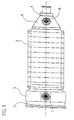
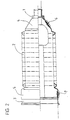
- the protective bellows shown in FIGS. 1 and 2 for a vehicle steering system exists from a fastening collar 1 of small diameter, a flexible Fold area 2, another fastening collar 3 of larger diameter and two transition zones 4 and 5 leading to a spacing of Attach fastening cuffs 1 and 3 to fold area 2.
- the cylindrical or frustoconical transition zones 4 and 5 contain as pressure compensation elements 6 and 7 coated, for example PP and TPFE manufactured fabrics over which at a sufficiently high Pressure difference there is an extensive pressure equalization. It is advantageous that in the transition zones 4 and 5 only a small load on the Bellow occurs due to changes in shape.
- annular groove 8 is introduced into the pressure compensation element 7, which with a circular projection 9 of a support surface 10 of the Bellow corresponds.
- a trained and inserted into the bellows Pressure compensation element ensures continuous pressure compensation, of changes in temperature and mechanical Stresses is required.
Landscapes
- Engineering & Computer Science (AREA)
- General Engineering & Computer Science (AREA)
- Mechanical Engineering (AREA)
- Diaphragms And Bellows (AREA)
Description
- Fig. 1
- einen flexiblen Schutzbalg, der in den beiden Übergangszonen vom Befestigungsbund zum Faltenbereich je ein Druckausgleichselement aufweist,
- Fig. 2
- einen um 90° zur Längsachse gedrehten und teilweise geschnittenen Faltenbalg gemäß Fig. 1 und
- Fig. 3
- eine vergrößerte Darstellung einer Übergangszone von einem Befestigungsbund in einen Faltenbereich mit integriertem Druckausgleichselement.
Claims (6)
- Flexibler Schutzbalg, vorzugsweise zum Schutz von Fahrzeugbauteilen, insbesondere Lenkungsfaltenbalg, dessen Wandung zumindest aus einem ersten und einem zweiten jeweils endseitig angeordneten, auf einem Bauteil festlegbaren Befestigungsbund (1,3) und einem zwischen dem ersten und dem zweiten Befestigungsbund (1,3) verlaufenden, zu dem zu schützenden Bauteil beabstandeten, flexiblen Zwischenbereich (2) besteht und der zumindest ein Druckausgleichselement (6,7) in Form eines gasdurchlässigen Festkörperfilters enthält,
dadurch gekennzeichnet, dass das zumindest eine gasdurchlässige, flüssigkeitsdichte Druckausgleichselement (6, 7) in der Übergangszone (4, 5) vom Befestigungsbund (1, 3) zum flexiblen Zwischenbereich (2) in die Wandung des Schutzbalges eingesetzt ist oder zumindest einen Teilbereich der Wandung der Übergangszone (4, 5) bildet. - Flexibler Schutzbalg nach Anspruch 1, dadurch gekennzeichnet, daß in dem Druckausgleichselement (6, 7) als Filter ein Gewebe zum Einsatz kommt.
- Flexibler Schutzbalg nach Anspruch 2, dadurch gekennzeichnet, daß die Fäden des Gewebes mit einer Beschichtung versehen sind.
- Flexibler Schutzbalg nach Anspruch 1, dadurch gekennzeichnet, daß das Druckausgleichselement (6,7) in einer Aussparung der Wandung des Schutzbalges fixiert ist.
- Flexibler Schutzbalg nach Anspruch 4, dadurch gekennzeichnet, daß das Druckausgleichselement (6, 7) in radialer Richtung formschlüssig von außen in den Schutzbalg eingesetzt ist.
- Flexibler Schutzbalg nach Anspruch 4 oder 5, dadurch gekennzeichnet, daß der Randbereich des eingesetzten Druckausgleichselements (6,7) von einem stoffschlüssig mit dem angrenzenden Schutzbalg verbundenen Sicherungselement (11) überdeckt ist.
Applications Claiming Priority (2)
| Application Number | Priority Date | Filing Date | Title |
|---|---|---|---|
| DE19917998A DE19917998C2 (de) | 1999-04-21 | 1999-04-21 | Flexibler Schutzbalg, vorzugsweise zum Schutz von Fahrzeugbauteilen |
| DE19917998 | 1999-04-21 |
Publications (3)
| Publication Number | Publication Date |
|---|---|
| EP1048865A2 EP1048865A2 (de) | 2000-11-02 |
| EP1048865A3 EP1048865A3 (de) | 2001-04-25 |
| EP1048865B1 true EP1048865B1 (de) | 2004-01-02 |
Family
ID=7905301
Family Applications (1)
| Application Number | Title | Priority Date | Filing Date |
|---|---|---|---|
| EP00108540A Expired - Lifetime EP1048865B1 (de) | 1999-04-21 | 2000-04-19 | Flexibler Schutzbalg, vorzugsweise zum Schutz von Fahrzeugbauteilen |
Country Status (2)
| Country | Link |
|---|---|
| EP (1) | EP1048865B1 (de) |
| DE (2) | DE19917998C2 (de) |
Cited By (1)
| Publication number | Priority date | Publication date | Assignee | Title |
|---|---|---|---|---|
| DE102004042552B4 (de) * | 2003-09-02 | 2007-06-06 | Jtekt Europe S.A.S. | "Vorrichtung zum Ausgleich der Drücke zwischen dem Inneren und Äußeren eines Zahnstangenlenksystems für Kraftfahrzeuge" |
Families Citing this family (14)
| Publication number | Priority date | Publication date | Assignee | Title |
|---|---|---|---|---|
| GB2369864B (en) | 2000-12-05 | 2004-11-03 | Draftex Ind Ltd | Protective covers |
| FR2843931B1 (fr) * | 2002-09-03 | 2005-04-01 | Soc Mecanique Irigny | Dispositif d'equilibrage des pressions entre l'interieur et l'exterieur d'une direction a cremaillere de vehicule |
| FR2881501B1 (fr) * | 2005-02-02 | 2008-09-12 | Bosch Gmbh Robert | Manchon de protection pour systeme mecanique coulissant |
| DE102006059950B4 (de) * | 2006-12-19 | 2012-03-22 | Ifa-Technologies Gmbh | Dichtmanschette für Fahrzeuggelenkwellen |
| DE102007015073B4 (de) * | 2006-12-28 | 2010-10-07 | Ifa-Technologies Gmbh | Rollbalg für Gelenkwellen von Kraftfahrzeugen |
| FR2910949B1 (fr) | 2006-12-29 | 2009-02-27 | Trelleborg Prodyn Soc Par Acti | Dispositif de protection d'organes de direction et/ou de transmission et soufflet de protection equipant un tel dispositif |
| DE102007015860A1 (de) | 2007-04-03 | 2008-10-09 | Zf Friedrichshafen Ag | Schutzhülle für ein Kolben-Zylinderaggregat |
| DE102008019267B4 (de) * | 2008-04-17 | 2010-06-24 | Knorr-Bremse Systeme für Nutzfahrzeuge GmbH | Scheibenbremse |
| DE102008021646B4 (de) * | 2008-04-30 | 2015-04-09 | Knorr-Bremse Systeme für Nutzfahrzeuge GmbH | Scheibenbremse für ein Nutzfahrzeug |
| EP2133604B1 (de) | 2008-06-11 | 2013-03-13 | Carl Freudenberg KG | Balg mit einem sich axial erstreckenden Druckausgleichselement |
| WO2010039244A1 (en) * | 2008-09-30 | 2010-04-08 | Gore Enterprise Holdings, Inc. | Venting device |
| DE102017120172B4 (de) | 2017-09-01 | 2026-03-19 | Thyssenkrupp Ag | Filtervorrichtung sowie Befestigungsmittel mit einer solchen Filtervorrichtung |
| DE102017217633A1 (de) | 2017-10-04 | 2019-04-04 | Volkswagen Aktiengesellschaft | Verfahren zur Herstellung eines Dämpfungselementes, insbesondere für das Lenksystem eines Kraftfahrzeuges bzw. Dämpfungselement, insbesondere für das Lenksystem eines Kraftfahrzeuges bzw. Lenksystem eines Kraftfahrzeuges |
| US10780756B1 (en) * | 2019-04-23 | 2020-09-22 | RB Distribution, Inc. | Purging dust boot |
Family Cites Families (7)
| Publication number | Priority date | Publication date | Assignee | Title |
|---|---|---|---|---|
| US3041885A (en) * | 1959-05-11 | 1962-07-03 | Baldwin Montrose Chemical Comp | Bellows |
| DE2034753C3 (de) * | 1970-07-14 | 1974-05-09 | Fa. Carl Freudenberg, 6940 Weinheim | Faltenbalg |
| DE2125117B2 (de) * | 1971-05-21 | 1976-06-16 | Faltenbalg | |
| US3927576A (en) * | 1974-08-01 | 1975-12-23 | Trw Inc | Boot seal filter vent |
| FR2414145A1 (fr) * | 1978-01-04 | 1979-08-03 | Citroen Sa | Joint de transmission a protecteur a soufflet |
| DE3049059C2 (de) * | 1980-12-24 | 1985-10-10 | Festo-Maschinenfabrik Gottlieb Stoll, 7300 Esslingen | Faltenbalg für eine Arbeitszylinderanordnung |
| DE4033275A1 (de) * | 1990-10-19 | 1992-04-30 | Loehr & Bromkamp Gmbh | Roll- oder faltenbalg fuer ein gleichlaufdrehgelenk mit druckausgleich im gelenkraum |
-
1999
- 1999-04-21 DE DE19917998A patent/DE19917998C2/de not_active Expired - Lifetime
-
2000
- 2000-04-19 DE DE50004901T patent/DE50004901D1/de not_active Expired - Lifetime
- 2000-04-19 EP EP00108540A patent/EP1048865B1/de not_active Expired - Lifetime
Cited By (1)
| Publication number | Priority date | Publication date | Assignee | Title |
|---|---|---|---|---|
| DE102004042552B4 (de) * | 2003-09-02 | 2007-06-06 | Jtekt Europe S.A.S. | "Vorrichtung zum Ausgleich der Drücke zwischen dem Inneren und Äußeren eines Zahnstangenlenksystems für Kraftfahrzeuge" |
Also Published As
| Publication number | Publication date |
|---|---|
| EP1048865A3 (de) | 2001-04-25 |
| EP1048865A2 (de) | 2000-11-02 |
| DE50004901D1 (de) | 2004-02-05 |
| DE19917998C2 (de) | 2001-09-20 |
| DE19917998A1 (de) | 2000-11-09 |
Similar Documents
| Publication | Publication Date | Title |
|---|---|---|
| EP0897317B1 (de) | Endscheibe für ein ringfilterelement mit radial wirkender dichtung | |
| DE69306975T2 (de) | Farbspritzvorrichtung mit rotierendem zerstäubungselement und werkzeug zum montieren und demontieren dieses elements | |
| DE4412132C5 (de) | Abdichtung für eine Gelenkkreuzbüchse | |
| DE102016203070B3 (de) | Anschlussstutzen und Wärmemanagementmodul mit einem solchen | |
| DE19917998C2 (de) | Flexibler Schutzbalg, vorzugsweise zum Schutz von Fahrzeugbauteilen | |
| DE2900026C3 (de) | Entlüftungsvorrichtung für ein Wellengelenk mit Faltenbalgabdichtung | |
| DE69507330T2 (de) | Schutzbälge | |
| EP0311756A2 (de) | Einfüllstutzen für einen Kraftstoffbehälter eines Kraftfahrzeugs | |
| DE69407724T2 (de) | Abdichtungsvorrichtung für einen Fluidumdurchgang durch ein Rollenlager, und Rollenlager mit dieser Vorrichtung | |
| EP0280018B1 (de) | Befestigung der Dichtungsmanschette eines Kugelgelenkes für Kraftfahrzeuge | |
| DE69612177T2 (de) | Scheibenwischer-Mechanismus mit Führungs-und Dichtungsmittel zur Antriebaxen-Durchquerung eines Bleches | |
| WO2018192597A1 (de) | Dichtungsanordnung eines radlagers | |
| DE3517959C2 (de) | ||
| DE19754699A1 (de) | Abdichtung für eine Lagerbüchse | |
| EP1145880B1 (de) | Lagerung für einen Stabilisator einer Radaufhängung für Kraftfahrzeuge | |
| DE3739514C2 (de) | Dichtring | |
| EP1208322B1 (de) | Schlauchanordnung | |
| DE2943137C2 (de) | Radblende, insbesondere für Räder von Personenkraftwagen | |
| EP0931955A1 (de) | Luftfeder mit einem Rollbalg | |
| EP3688326B1 (de) | Gelenkanordnung | |
| DE112006001992B4 (de) | Kugelgelenk und Dichtungsmanschette für ein solches Kugelgelenk | |
| DE1750006A1 (de) | Kegelrollenlager | |
| DE3420523A1 (de) | Radialwellendichtring | |
| DE3425158C2 (de) | ||
| DE19951714C2 (de) | Heizungsanlage eines Kraftfahrzeuges |
Legal Events
| Date | Code | Title | Description |
|---|---|---|---|
| PUAI | Public reference made under article 153(3) epc to a published international application that has entered the european phase |
Free format text: ORIGINAL CODE: 0009012 |
|
| AK | Designated contracting states |
Kind code of ref document: A2 Designated state(s): DE ES FR GB IT PT |
|
| AX | Request for extension of the european patent |
Free format text: AL;LT;LV;MK;RO;SI |
|
| PUAL | Search report despatched |
Free format text: ORIGINAL CODE: 0009013 |
|
| AK | Designated contracting states |
Kind code of ref document: A3 Designated state(s): AT BE CH CY DE DK ES FI FR GB GR IE IT LI LU MC NL PT SE |
|
| AX | Request for extension of the european patent |
Free format text: AL;LT;LV;MK;RO;SI |
|
| RIC1 | Information provided on ipc code assigned before grant |
Free format text: 7F 16D 3/84 A, 7F 16J 3/04 B |
|
| 17P | Request for examination filed |
Effective date: 20011025 |
|
| AKX | Designation fees paid |
Free format text: DE ES FR GB IT PT |
|
| 17Q | First examination report despatched |
Effective date: 20021205 |
|
| GRAH | Despatch of communication of intention to grant a patent |
Free format text: ORIGINAL CODE: EPIDOS IGRA |
|
| GRAS | Grant fee paid |
Free format text: ORIGINAL CODE: EPIDOSNIGR3 |
|
| GRAA | (expected) grant |
Free format text: ORIGINAL CODE: 0009210 |
|
| AK | Designated contracting states |
Kind code of ref document: B1 Designated state(s): DE ES FR GB IT PT |
|
| PG25 | Lapsed in a contracting state [announced via postgrant information from national office to epo] |
Ref country code: GB Free format text: LAPSE BECAUSE OF FAILURE TO SUBMIT A TRANSLATION OF THE DESCRIPTION OR TO PAY THE FEE WITHIN THE PRESCRIBED TIME-LIMIT Effective date: 20040102 |
|
| REG | Reference to a national code |
Ref country code: GB Ref legal event code: FG4D Free format text: NOT ENGLISH |
|
| REF | Corresponds to: |
Ref document number: 50004901 Country of ref document: DE Date of ref document: 20040205 Kind code of ref document: P |
|
| PG25 | Lapsed in a contracting state [announced via postgrant information from national office to epo] |
Ref country code: ES Free format text: LAPSE BECAUSE OF FAILURE TO SUBMIT A TRANSLATION OF THE DESCRIPTION OR TO PAY THE FEE WITHIN THE PRESCRIBED TIME-LIMIT Effective date: 20040413 |
|
| GBV | Gb: ep patent (uk) treated as always having been void in accordance with gb section 77(7)/1977 [no translation filed] |
Effective date: 20040102 |
|
| ET | Fr: translation filed | ||
| PLBE | No opposition filed within time limit |
Free format text: ORIGINAL CODE: 0009261 |
|
| STAA | Information on the status of an ep patent application or granted ep patent |
Free format text: STATUS: NO OPPOSITION FILED WITHIN TIME LIMIT |
|
| 26N | No opposition filed |
Effective date: 20041005 |
|
| PGFP | Annual fee paid to national office [announced via postgrant information from national office to epo] |
Ref country code: IT Payment date: 20060430 Year of fee payment: 7 |
|
| PG25 | Lapsed in a contracting state [announced via postgrant information from national office to epo] |
Ref country code: PT Free format text: LAPSE BECAUSE OF NON-PAYMENT OF DUE FEES Effective date: 20040602 |
|
| PGFP | Annual fee paid to national office [announced via postgrant information from national office to epo] |
Ref country code: FR Payment date: 20090414 Year of fee payment: 10 |
|
| PG25 | Lapsed in a contracting state [announced via postgrant information from national office to epo] |
Ref country code: IT Free format text: LAPSE BECAUSE OF NON-PAYMENT OF DUE FEES Effective date: 20070419 |
|
| REG | Reference to a national code |
Ref country code: FR Ref legal event code: ST Effective date: 20101230 |
|
| PG25 | Lapsed in a contracting state [announced via postgrant information from national office to epo] |
Ref country code: FR Free format text: LAPSE BECAUSE OF NON-PAYMENT OF DUE FEES Effective date: 20100430 |
|
| PGFP | Annual fee paid to national office [announced via postgrant information from national office to epo] |
Ref country code: DE Payment date: 20190430 Year of fee payment: 20 |
|
| REG | Reference to a national code |
Ref country code: DE Ref legal event code: R071 Ref document number: 50004901 Country of ref document: DE |