EP1046409A2 - Implantierbarer Kardiovertierer/Defibrillator mit automatischer Einstellung von Erkennungskriterien einer Arhythmie - Google Patents
Implantierbarer Kardiovertierer/Defibrillator mit automatischer Einstellung von Erkennungskriterien einer Arhythmie Download PDFInfo
- Publication number
- EP1046409A2 EP1046409A2 EP20000303027 EP00303027A EP1046409A2 EP 1046409 A2 EP1046409 A2 EP 1046409A2 EP 20000303027 EP20000303027 EP 20000303027 EP 00303027 A EP00303027 A EP 00303027A EP 1046409 A2 EP1046409 A2 EP 1046409A2
- Authority
- EP
- European Patent Office
- Prior art keywords
- detector
- arrhythmia
- detection
- ventricular
- detection system
- Prior art date
- Legal status (The legal status is an assumption and is not a legal conclusion. Google has not performed a legal analysis and makes no representation as to the accuracy of the status listed.)
- Granted
Links
- 238000001514 detection method Methods 0.000 title claims abstract description 142
- 206010003119 arrhythmia Diseases 0.000 title claims abstract description 63
- 230000006793 arrhythmia Effects 0.000 title claims abstract description 61
- 238000012790 confirmation Methods 0.000 claims abstract description 62
- 230000002763 arrhythmic effect Effects 0.000 claims abstract description 47
- 230000002861 ventricular Effects 0.000 claims description 58
- 230000004913 activation Effects 0.000 claims description 35
- 238000001994 activation Methods 0.000 claims description 35
- 239000003990 capacitor Substances 0.000 claims description 24
- 230000035945 sensitivity Effects 0.000 claims description 13
- 206010047281 Ventricular arrhythmia Diseases 0.000 claims description 6
- 238000002407 reforming Methods 0.000 claims description 5
- 230000004044 response Effects 0.000 claims description 4
- 208000003663 ventricular fibrillation Diseases 0.000 description 35
- 238000000034 method Methods 0.000 description 15
- 230000001746 atrial effect Effects 0.000 description 10
- 239000004020 conductor Substances 0.000 description 8
- 238000010586 diagram Methods 0.000 description 6
- 230000001862 defibrillatory effect Effects 0.000 description 5
- 238000011022 operating instruction Methods 0.000 description 5
- 210000005245 right atrium Anatomy 0.000 description 5
- 230000008569 process Effects 0.000 description 4
- 210000005241 right ventricle Anatomy 0.000 description 4
- 230000035939 shock Effects 0.000 description 4
- 238000012935 Averaging Methods 0.000 description 3
- 230000000694 effects Effects 0.000 description 3
- 102100026827 Protein associated with UVRAG as autophagy enhancer Human genes 0.000 description 2
- 101710102978 Protein associated with UVRAG as autophagy enhancer Proteins 0.000 description 2
- 230000006870 function Effects 0.000 description 2
- 230000002401 inhibitory effect Effects 0.000 description 2
- 230000033764 rhythmic process Effects 0.000 description 2
- 230000007704 transition Effects 0.000 description 2
- 210000002620 vena cava superior Anatomy 0.000 description 2
- 206010003658 Atrial Fibrillation Diseases 0.000 description 1
- 206010003662 Atrial flutter Diseases 0.000 description 1
- 238000013459 approach Methods 0.000 description 1
- 206010003668 atrial tachycardia Diseases 0.000 description 1
- 230000001788 irregular Effects 0.000 description 1
- 210000005246 left atrium Anatomy 0.000 description 1
- 210000005240 left ventricle Anatomy 0.000 description 1
- 238000012986 modification Methods 0.000 description 1
- 230000004048 modification Effects 0.000 description 1
- 230000001105 regulatory effect Effects 0.000 description 1
- 238000007920 subcutaneous administration Methods 0.000 description 1
- 238000002560 therapeutic procedure Methods 0.000 description 1
- 210000001631 vena cava inferior Anatomy 0.000 description 1
- 206010047302 ventricular tachycardia Diseases 0.000 description 1
Images


Classifications
-
- A—HUMAN NECESSITIES
- A61—MEDICAL OR VETERINARY SCIENCE; HYGIENE
- A61N—ELECTROTHERAPY; MAGNETOTHERAPY; RADIATION THERAPY; ULTRASOUND THERAPY
- A61N1/00—Electrotherapy; Circuits therefor
- A61N1/18—Applying electric currents by contact electrodes
- A61N1/32—Applying electric currents by contact electrodes alternating or intermittent currents
- A61N1/38—Applying electric currents by contact electrodes alternating or intermittent currents for producing shock effects
- A61N1/39—Heart defibrillators
- A61N1/3956—Implantable devices for applying electric shocks to the heart, e.g. for cardioversion
-
- A—HUMAN NECESSITIES
- A61—MEDICAL OR VETERINARY SCIENCE; HYGIENE
- A61N—ELECTROTHERAPY; MAGNETOTHERAPY; RADIATION THERAPY; ULTRASOUND THERAPY
- A61N1/00—Electrotherapy; Circuits therefor
- A61N1/18—Applying electric currents by contact electrodes
- A61N1/32—Applying electric currents by contact electrodes alternating or intermittent currents
- A61N1/36—Applying electric currents by contact electrodes alternating or intermittent currents for stimulation
- A61N1/362—Heart stimulators
- A61N1/3621—Heart stimulators for treating or preventing abnormally high heart rate
-
- A—HUMAN NECESSITIES
- A61—MEDICAL OR VETERINARY SCIENCE; HYGIENE
- A61N—ELECTROTHERAPY; MAGNETOTHERAPY; RADIATION THERAPY; ULTRASOUND THERAPY
- A61N1/00—Electrotherapy; Circuits therefor
- A61N1/18—Applying electric currents by contact electrodes
- A61N1/32—Applying electric currents by contact electrodes alternating or intermittent currents
- A61N1/38—Applying electric currents by contact electrodes alternating or intermittent currents for producing shock effects
- A61N1/39—Heart defibrillators
- A61N1/3925—Monitoring; Protecting
Definitions
- the present invention is generally directed to an implantable cardioverter-defibrillator which applies arrhythmia-terminating electrical energy to a heart when an arrhythmic episode is detected.
- the present invention is more particularly directed to such a device, wherein arrhythmic episode detection criteria are adjusted in response to arrhythmic episode detection confirmation results.
- Implantable cardioverters-defibrillators such as implantable ventricular defibrillators, are well known in the art. Such devices include an arrhythmia detector which detects an arrhythmic episode of the heart and an output circuit or generator which applies electrical energy to a heart when an arrhythmic episode is detected to terminate the detected arrhythmia.
- the performance of an arrhythmia detector is generally measured by its sensitivity and specificity. Sensitivity is the measure of how well a detector detects all of the arrhythmic episodes. For example, a detector that has a sensitivity of 100% detects all arrhythmic episodes of the type intended to be detected which occur. Specificity, on the other hand, is the measure of how well the detector is able to distinguish or discriminate the arrhythmia intended to be detected from other arrhythmias. For example, an arrhythmia detector which has a specificity of 100% detects only the arrhythmia intended to be detected, and no others.
- ventricular fibrillation detector which is has a sensitivity of 100% and a specificity of 100% is able to detect all ventricular fibrillations episodes that occur(100% sensitive) while at the same time not mistaking any other form of arrhythmic episode for ventricular fibrillation (100% specific).
- the detection parameters or criteria used in the initial detection of ventricular fibrillation episodes represent a difficult tradeoff for the physician. If the number of heartbeats to be analyzed is set too high, there could be a significant delay in the detection of the ventricular fibrillation episodes. If the number of heartbeats to be analyzed is set too low, the confidence that a rhythm detected as ventricular fibrillation truly being ventricular fibrillation is reduced. If the criteria applied to the analyzed beats are set too high, the detection will be overly specific and relatively insensitive resulting in the potential that a ventricular fibrillation episode will go undetected. Lastly, if the criteria applied to the analyzed beats are too low, the opposite problem can occur and the detection will be overly sensitive and relatively unspecific resulting in inappropriate shocks being delivered to the heart.
- the present invention addresses these issues. More particularly, as will be seen hereinafter, the confirmation results of the confirmation detection are utilized for the automatic adjustment or regulation of the initial arrhythmia detection criteria to assure maximum sensitivity with appropriate specificity in the initial arrhythmic episode detection parameters or criteria.
- the invention provides an arrhythmia detection system that provides automatic detection criteria adjustment for use in an implantable cardioverter-defibrillator that applies arrhythmia terminating electrical energy to a heart responsive to detection of an arrhythmic episode of the heart.
- a first detector detects arrhythmic episodes of the heart in accordance with detection criteria.
- a second detector confirms the detection of each arrhythmic episode by the first detector and a detection criteria regulator adjusts the detection criteria of the first detector responsive to the second detector.
- the detection criteria regulator adjusts sensitivity and specificity detection criteria of the first detector.
- the second, or confirmation detector provides one of successful and unsuccessful confirmation results for each arrhythmic episode detected by the first detector.
- the detection system further includes a counter that counts consecutive confirmation results provided by the second detector. The detection criteria regulator adjusts the detection criteria of the first detector in response to the counter counting either at least two consecutive successful confirmation results or two consecutive unsuccessful confirmation results.
- the arrhythmia detection system includes a processor, coupled to a ventricular activation detector, that times successive time spans between successive detected ventricular activations and executes an X out of Y routine wherein Y is the total number of successive time spans to be timed for a ventricular arrhythmic episode to be detected and X is the number of time spans shorter than a predetermined time span of the successive number of total time spans required for a ventricular arrhythmic episode to be detected.
- the detection criteria regulator adjusts the values of X and y.
- the detection system includes a ventricular activation rate variability factor calculator that determines the ventricular activation rate variability.
- the detection criteria regulator causes the number of heartbeats to be analyzed to be increased or to remain constant.
- an abort stage causes the application of arrhythmia terminating electrical energy to be inhibited if an arrhythmic episode detection confirmation is unsuccessful.
- the storage capacitor that stores the arrhythmia terminating electrical energy may be reformed when such reforming is required and if a confirmation of an arrhythmic episode detection is unsuccessful.
- an arrhythmia detection system that provides automatic detection criteria adjustment comprising:
- a method of adjusting arrhythmic episode detection criteria including the steps of:
- the adjusting step includes adjusting sensitivity and specificity detection criteria.
- the confirming step includes providing one of successful and unsuccessful confirmation results for each arrhythmic episode detected, and wherein the method further includes counting consecutive confirmation results provided by the confirming step and wherein the adjusting step is performed when at least two consecutive successful confirmation results have been counted.
- the confirming step includes providing one of a successful and unsuccessful confirmation results for each arrhythmic episode detected, and wherein the method further includes counting consecutive confirmation results provided by the confirming step and wherein the adjusting step is performed when at least two consecutive unsuccessful confirmation results have been counted.
- the detecting step includes detecting ventricular arrhythmic episodes and wherein the method further includes the steps of detecting ventricular activations of the heart, timing successive time spans between successive detected ventricular activations and executing an X out of Y routine wherein Y is the total number of successive time spans to be timed for ventricular arrhythmia detection and X is the number of time spans shorter than a predetermined time span out of the successive number of total time spans required for a ventricular arrhythmic episode to be detected, and preferably the confirming step includes providing one of successful and unsuccessful confirmation results for each arrhythmic episode detected, and wherein the method further includes counting consecutive confirmation results provided by the confirming step and wherein the adjusting step is performed when at least two consecutive successful confirmation results have been counted, and preferably the adjusting step includes decrementing X and Y when the at least two consecutive successful confirmation results have been counted, and preferably the decrementing step includes decrementing both X and Y by one, and/or including the further step of determining
- the confirming step includes providing one of successful and unsuccessful confirmation results for each arrhythmic episode detected, and wherein the method further includes counting consecutive confirmation results provided by the confirming step and wherein the adjusting step is performed when at least two consecutive unsuccessful confirmation results have been counted, and preferably the adjusting step includes incrementing X and Y when at least two consecutive unsuccessful confirmation results have been counted, and preferably incrementing step includes incrementing both X and Y by one and/or including the further step of determining if a ventricular activation rate variability exceeds a given factor and wherein the incrementing step is performed when the at least two consecutive unsuccessful confirmation results have been counted and if the ventricular activation rate variability factor is greater than the given factor, and preferably the incrementing step includes incrementing both X and Y by two and/or the ventricular activation rate variability factor determining step includes determining the ventricular activation rate variability corresponding to the Y time spans.
- the confirming step includes the steps of detecting ventricular activations of the heart, timing a given number of consecutive time spans between consecutive detected ventricular activations, averaging the given number of time spans, and confirming the detection of an arrhythmic episode if the average of the given number of time spans is less than a predetermined time span.
- the method further includes the further step of inhibiting application of the arrhythmia terminating energy upon failing to confirm the detection of an arrhythmic episode
- the cardioverter-defibrillator includes a storage capacitor that stores the arrhythmia terminating electrical energy and wherein the method further includes the steps of determining if the capacitor requires reforming, causing the capacitor to store the arrhythmia terminating electrical energy and inhibiting the application of the arrhythmia terminating electrical energy upon failing to confirm the detection of an arrhythmic episode and if the capacitor requires reforming.
- FIG. 1 it illustrates heart 10 in need of ventricular arrhythmia cardioversion-defibrillation and an associated implantable ventricular cardioverter-defibrillator 30 embodying the present invention.
- the portions of the heart 10 illustrated in FIG. 1 are the right ventricle 12 , the left ventricle 14 , the right atrium 16 , and the left atrium 18 .
- Also illustrated are the superior vena cava 20 and inferior vena cava 27 .
- the cardioverter-defibrillator 30 is arranged to be implanted in an upper left chest portion of a patient within a subcutaneous pocket.
- the implantable device 30 includes a first endocardial lead 32 which is of the "single-pass" type.
- the lead 32 includes a first shock coil 34 arranged to be disposed within the right ventricle 12 , a second shock coil 36 proximal to the shock coil electrode 34 and arranged to be disposed within the right atrium 16 or superior vena cava 20 , and a distal tip pacing electrode 38 .
- the implantable device 30 further includes a second endocardial lead 42 having an electrode pair including a distal electrode 44 and a proximal electrode 46 .
- the implantable cardioverter-defibrillator 30 includes a hermetically sealed, electrically conductive enclosure 50 . Then an quantity of cardioverting or defibrillating electrical energy is applied to the heart 10 , in accordance with this preferred embodiment, the electrodes 34 and 36 are connected in parallel and the quantity of arrhythmia terminating electrical energy is applied between the parallel connection of electrode 36 and the electrically conductive enclosure 50 of the implantable device 30 and electrode 34 . Alternatively, the cardioverting or defibrillating quantity of electrical energy may be applied between electrode 34 and the electrically conductive enclosure 50 without employing electrode 36 .
- Electrodes 44 and 46 of lead 42 support sensing of right atrial electrical activity and delivery of atrial pacing pulses to the right atrium 16 .
- the implantable cardioverter-defibrillator 30 includes within the enclosure 50 a ventricular sense channel 52 , an atrial sense channel 62 , and a pacing pulse generator 70 including a first or atrial pacing pulse generator 72 for providing atrial pacing pulses and a second or ventricular pacing pulse generator 74 for providing ventricular pacing pulses.
- the device 30 further includes a microprocessor 80 , a memory 110 , and a telemetry stage 150 .
- the device 30 still further includes and cardioversion-defibrillation generator 166 including a charging circuit 160 , a storage capacitor 162 , and a switch 164 .
- the ventricular sense channel 52 includes a sense amplifier 54 and a threshold detector 56 .
- the sense amplifier 54 has an input coupled to electrode 38 of lead 32 by a conductor 138 of the lead 32 .
- the sense amplifier 54 has another input which is coupled to electrode 34 of lead 32 by another conductor 134 of the lead 32 .
- the sense amplifier 54 further includes an output which forms an input to the threshold detector 56 .
- the threshold detector 56 has an output which is coupled to the microprocessor 80 .
- the sense amplifier 54 together with electrodes 38 and 34 sense electrical activity in the right ventricle 12 .
- the threshold detector 56 provides an input signal to the microprocessor 80 indicating that a ventricular activation or R wave has been detected. Such detection is well known in the art.
- the atrial sense channel 62 includes a sense amplifier 64 and a threshold detector 66 .
- the sense amplifier 64 has an input which is coupled to electrode 44 of lead 42 by a conductor 144 of lead 42 .
- the sense amplifier 64 has another input which is coupled to the electrode 46 of lead 42 by another conductor 146 of lead 42 .
- the sense amplifier has an output which forms an input to the threshold detector 66 and the threshold detector 66 has an output which is coupled to the microprocessor 80 .
- the sense amplifier 64 together with electrodes 44 and 46 , sense electrical activity in the right atrium.
- the threshold detector 66 provides an input signal to the microprocessor 80 indicating that an atrial activation or P wave has been detected. Again, such detection is also well known in the art.
- the first or atrial pulse generator 72 has outputs coupled to electrodes 44 and 46 of lead 42 by conductors 144 and 146 respectively of lead 42 . This permits atrial pacing pulses produced by the atrial pacer 72 to be applied to the right atrium 16 .
- the second or ventricular pulse generator 74 has outputs coupled to electrodes 34 and 38 of lead 32 by conductors 134 and 138 respectively of lead 32 . This permits ventricular pacing pulses produced by the ventricular pacer 74 to be applied to the right ventricle 12 .
- the cardioversion-defibrillation generator 166 applies a quantity of arrhythmia terminating electrical energy to the heart 10 .
- the charging circuit 160 charges the storage capacitor 162 with the quantity of electrical energy to be applied to the heart upon the detection of a ventricular arrhythmia, such as ventricular fibrillation, as will be described subsequently.
- the switch 164 applies the quantity of electrical energy from the storage capacitor 162 to the heart.
- the switch has an output coupled to electrode 34 of lead 32 by the conductor 134 of lead 32 and another output which is coupled to electrode 36 by a conductor 136 of lead 32 .
- another output of the switch 164 is coupled to the electrically conductive enclosure 50 .
- the microprocessor 80 controls the overall functioning of the implantable cardioverter-defibrillator 30 .
- the microprocessor executes operating instructions stored in the memory 110 and utilizes various parameters also stored in memory 110 .
- the memory 110 stores the operating instructions defining various pacing modalities which may be provided by the device 30 in a storage location 112 .
- Detection parameters such as the programmable thresholds of threshold detectors 56 and 66 may be stored in storage location 114 .
- a ventricular fibrillation detector executes an X out of Y algorithm, and the values of X and Y may be stored in a storage location 116 .
- the operating instructions defining ventricular defibrillation therapy may be stored in a storage location 118 .
- defibrillation parameters such as defibrillating energies may be stored in a storage location 120 .
- the telemetry stage 150 permits modality selections and storage of detection parameters, X and Y values, and defibrillation parameters in the memory 110 to be made through the use of an external programmer (not shown) of the type well known in the art.
- the telemetry stage includes a receiver 152 which receives telemetry commands including mode selection and parameter commands from the programmer.
- the receiver 152 conveys the commands to the microprocessor 80 which then stores them in the memory 110 .
- the telemetry stage 150 also includes a transmitter 154 .
- the transmitter may be used for transmitting data to the programmer.
- the transmitted data may include sensed electograms or status information, for example, as is well known in the art.
- the microprocessor 80 is coupled to the memory 110 by a multiple-bit address bus 120 and a bi-directional, multiple-bit data bus 122 .
- the microprocessor 80 uses the address bus 120 to fetch operating instructions or programmable parameters from the memory at address locations defined on the address bus 120 .
- the fetched instructions and parameters are conveyed to the microprocessor 80 over the data bus 122 .
- the microprocessor 80 may store data in the memory 110 at memory locations defined on the address bus 120 .
- the microprocessor 80 conveys the data to the memory over the data bus 122 .
- Such microprocessor and memory operation are conventional in the art.
- the microprocessor When executing the operating instructions stored in memory 110 , the microprocessor implements a number of functional stages in accordance with the present invention. These stages include a first detector 82 including a timer 84 , a counter 86 , and an X of Y stage 88 .
- the functional stages of microprocessor 80 further include a second detector 90 including a timer 92 , an averaging stage 94 , an abort stage 96 , and a capacitor reform timing stage 98 .
- the functional stages further include a detection criteria regulator 100 including a confirmation counter 102 , a variability factor determining stage 104 , a decrementer 106 , and incrementer 108 .
- the functional stages include a charge control 105 and a synchronizing stage 107 .
- the first detector 82 , second detector 90 and detection criteria regulator 100 form an arrhythmia detection system 81 embodying the present invention.
- the charge control 105 causes the charger 160 to begin charging the storage capacitor 162 with the arrhythmia terminating electrical energy. Also, as the storage capacitor 162 is being charged, the second detector 90 executes a ventricular fibrillation confirmation detection. The successful confirmation or unsuccessful confirmation results of the second detector 94 are counted by the confirmation counter 102 of the detection criteria regulator 100 . When a predetermined number of consecutive successful or unsuccessful confirmations have occurred, the detection criteria regulator 100 adjusts the sensitivity and specificity of the detection criteria of the first detector 82 .
- the synchronizing stage 107 causes the switch 164 to operate in synchronization with a detected R wave for applying the arrhythmia terminating electrical energy to the heart 10 . If the confirmation of the ventricular fibrillation detection is unsuccessful, the abort stage 96 of the second detector will cause the application of the arrhythmia terminating electrical energy to be aborted and hence not applied to the heart 10 .
- the first detector 82 executes an X out of Y algorithm of the type well known in the art. As will be appreciated by those skilled in the art, other methodologies of initial ventricular fibrillation detection may be employed without departing from the present invention.
- the first detector 82 determines if X beats out of the last Y beats were fast. To that end, the timer 84 times time spans between ventricular activations detected by ventricular sense channel 52 . The counter 86 counts the time spans that are shorter than a predetermined time span. If X or more of the last Y beats are shorter than the predetermined time span, the first detector 82 will have detected a ventricular fibrillation.
- the short time spans may be on the order of 200-350 milliseconds.
- X is equal to 12 and Y is equal to 16
- the detector 82 will determine if 12 out of the last 16 beats were shorter than the predetermined span time. If 12 or more of the beats of the last 16 beats were shorter than the predetermined time span, the detector 82 will consider ventricular fibrillation to have been detected.
- the charger 160 Upon the initial detection of ventricular fibrillation, the charger 160 as previously described begins to charge storage capacitor 162 . Also during the charging time, the second or confirmation detector 90 performs another detection to confirm the initial ventricular fibrillation detection. To confirm the original detection, the second detector 94 may, for example, monitor 4 more beats. If the average of these 4 beats is still considered fast, then the original ventricular fibrillation detection will be successfully confirmed and the arrhythmia terminating electrical energy will be applied as previously described. If the average of those 4 beats is considered not to be fast, then the confirmation is unsuccessful and the abort stage 96 will abort the application of the arrhythmia terminating electrical energy. For timing the time spans between the ventricular activations of the 4 beats, the detector 90 includes a timer 92 . The averaging stage 94 averages the time spans between the ventricular activations comprising the last 4 beats to provide the average.
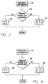
- FIG. 3 it illustrates a flow diagram of the operative steps which may be taken by the detection criteria regulator 100 if there is a successful confirmation of the original ventricular fibrillation episode detection.
- the first step in the process is step 170 wherein the original detection is confirmed.
- step 172 the confirmation counter 102 is addressed to determine if the previous episode was also confirmed. If the previous episode detection was not confirmed, the current values of X and Y in storage location 116 will remain unchanged in accordance with step 174 and the process returns.
- step 172 If in step 172 it is determined that the previous episode detection was confirmed, in addition to the delivery of the arrhythmia terminating electrical energy, the decrementing stage 106 in step 176 decrements both X and Y in storage location 116 by one. Following step 176 , the process will return.
- the detection criteria of detector 82 is adjusted such that the next time it detects an episode, one less heartbeat will be analyzed and one less heartbeat need be fast to satisfy the adjusted ventricular fibrillation detection criteria. This renders the new criteria more sensitive and less specific.
- step 178 it is determined that there has been an unsuccessful confirmation.
- step 180 it is determined if the previous episode detection was also unconfirmed. If the previous episode detection was not confirmed, in step 182 the current values of X and Y in storage location 116 are left unchanged and the process returns. However, if in step 180 it is determined that the previous episode detection was also unconfirmed, the values of X and Y in storage location 116 are incremented by one by the incrementing stage 108 in step 182 . This causes the adjusted detection criteria of the first detector 82 to be less sensitive and more specific.
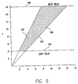
- FIG. 5 it illustrates the present invention in a broader context.
- the embodiment of the invention described above has the X and Y values being adjusted in lock step.
- an irregular quadrilateral describes an acceptable region for the X and Y values.
- the X value must be less than a certain extreme to limit the overall delay for detection. In this case, it is shown as a relatively conservative number of 16.
- the Y value must also be greater than a minimum level to ensure that a certain robust detection takes place. Experience has shown that a value of 4 is probably a minimum. Since X will not be greater than Y, the Y equals X line 190 obtains which is the highest specificity.
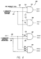
- FIG. 6 it illustrates in a logic diagram form the manner in which a detection criteria may be adjusted automatically using a "fuzzy" subset approach.
- a rate variability has been added.
- the rate variability may be, for example, a coefficient of a variability of the ventricular rate or a standard deviation.
- the rate variability may be determined by the variability factor determining stage 104 of the detection criteria regulator 100 of FIG. 2 .
- the logic circuit 200 includes AND gates 202 , 204 , 206 , and 208 .
- AND gate 202 includes an inverting input 210 and an input 212 .
- AND gate 204 includes inputs 214 and 216 .
- AND gate 206 includes an inverting input 218 and inputs 220 and 222 .
- AND gate 208 includes inputs 224 , 226 , and 228 .
- Inputs 210 , 214 , 218 , and 224 are coupled together and to a line 230 which is a logical high when the ventricular rate variability factor is high. For example, if the ventricular rate variability factor is a coefficient of a variability greater than, for example, 10%-20%, then the line 230 will be a logical high.
- Inputs 212 and 216 are coupled to another line 232 which is high when there have been two consecutive successful detection confirmations.
- Inputs 222 and 228 are coupled to a line 234 which is high when there are two consecutive unsuccessful detection confirmation.
- inputs 220 and 226 are coupled to a line 236 which is high when X is less than Y-1.
- the coefficient of variability of the rate is low and X is at least one less than Y, and two consecutive unsuccessful confirmations have occurred, than both the X and Y values are incremented. However, if the coefficient of variability of the rate is high, than the X and Y values are both incremented by two. This is to increase the statistical base of the rate to reduce the risk of the detections being aborted merely because of statistical while not raising the percentage of the beats that must be fast.
- the second detector 90 includes a capacitor reform timer 98 .
- the capacitor 162 would finish charging without being discharged into the heart to allow for the capacitor 162 to be reformed.
Landscapes
- Health & Medical Sciences (AREA)
- Cardiology (AREA)
- Heart & Thoracic Surgery (AREA)
- Engineering & Computer Science (AREA)
- Biomedical Technology (AREA)
- Nuclear Medicine, Radiotherapy & Molecular Imaging (AREA)
- Radiology & Medical Imaging (AREA)
- Life Sciences & Earth Sciences (AREA)
- Animal Behavior & Ethology (AREA)
- General Health & Medical Sciences (AREA)
- Public Health (AREA)
- Veterinary Medicine (AREA)
- Electrotherapy Devices (AREA)
Applications Claiming Priority (2)
| Application Number | Priority Date | Filing Date | Title |
|---|---|---|---|
| US298709 | 1999-04-23 | ||
| US09/298,709 US6169923B1 (en) | 1999-04-23 | 1999-04-23 | Implantable cardioverter-defibrillator with automatic arrhythmia detection criteria adjustment |
Publications (3)
| Publication Number | Publication Date |
|---|---|
| EP1046409A2 true EP1046409A2 (de) | 2000-10-25 |
| EP1046409A3 EP1046409A3 (de) | 2001-10-17 |
| EP1046409B1 EP1046409B1 (de) | 2003-08-13 |
Family
ID=23151695
Family Applications (1)
| Application Number | Title | Priority Date | Filing Date |
|---|---|---|---|
| EP00303027A Expired - Lifetime EP1046409B1 (de) | 1999-04-23 | 2000-04-11 | Implantierbarer Kardiovertierer/Defibrillator mit automatischer Einstellung von Erkennungskriterien einer Arhythmie |
Country Status (3)
| Country | Link |
|---|---|
| US (1) | US6169923B1 (de) |
| EP (1) | EP1046409B1 (de) |
| DE (1) | DE60004429T2 (de) |
Cited By (6)
| Publication number | Priority date | Publication date | Assignee | Title |
|---|---|---|---|---|
| EP1114653A2 (de) * | 2000-01-05 | 2001-07-11 | Pacesetter, Inc. | Ein implantierbares Kardiovertierungsgerät mit einem selbsteinstellenden Schwellwert für Therapieauswahl |
| WO2006081027A2 (en) * | 2005-01-25 | 2006-08-03 | Cameron Health, Inc. | Devices for adapting charge initiation for an implantable cardioverter-defibrillator |
| CN101107041B (zh) * | 2005-01-25 | 2012-08-29 | 卡梅伦保健公司 | 用于适应可植入心律转变器-除颤器充电启动的装置 |
| US8670826B2 (en) | 2005-01-25 | 2014-03-11 | Cameron Health, Inc. | Methods and devices for adapting charge initiation for an implantable defibrillator |
| AU2012211492B2 (en) * | 2005-01-25 | 2014-05-15 | Cameron Health, Inc. | Devices for adapting charge initiation for an implantable cardioverter-defribrillator |
| US9149645B2 (en) | 2013-03-11 | 2015-10-06 | Cameron Health, Inc. | Methods and devices implementing dual criteria for arrhythmia detection |
Families Citing this family (62)
| Publication number | Priority date | Publication date | Assignee | Title |
|---|---|---|---|---|
| US6866044B2 (en) * | 2000-09-18 | 2005-03-15 | Cameron Health, Inc. | Method of insertion and implantation of implantable cardioverter-defibrillator canisters |
| US6754528B2 (en) | 2001-11-21 | 2004-06-22 | Cameraon Health, Inc. | Apparatus and method of arrhythmia detection in a subcutaneous implantable cardioverter/defibrillator |
| US7069080B2 (en) * | 2000-09-18 | 2006-06-27 | Cameron Health, Inc. | Active housing and subcutaneous electrode cardioversion/defibrillating system |
| US6721597B1 (en) | 2000-09-18 | 2004-04-13 | Cameron Health, Inc. | Subcutaneous only implantable cardioverter defibrillator and optional pacer |
| US7146212B2 (en) * | 2000-09-18 | 2006-12-05 | Cameron Health, Inc. | Anti-bradycardia pacing for a subcutaneous implantable cardioverter-defibrillator |
| US6480742B2 (en) | 2000-12-26 | 2002-11-12 | Cardiac Pacemakers, Inc. | Pace counter isolation for cardiac resynchronization pacing |
| US7386344B2 (en) * | 2004-08-11 | 2008-06-10 | Cardiac Pacemakers, Inc. | Pacer with combined defibrillator tailored for bradycardia patients |
| US6751502B2 (en) * | 2001-03-14 | 2004-06-15 | Cardiac Pacemakers, Inc. | Cardiac rhythm management system with defibrillation threshold prediction |
| US7062322B2 (en) | 2001-12-18 | 2006-06-13 | Medtronic, Inc. | Rhythm-based transition to discriminatory arrhythmia classification |
| DE60328486D1 (de) | 2002-05-24 | 2009-09-03 | Angiotech Int Ag | Zusammensetzungen und verfahren zur beschichtung medizinischer implantate |
| US7162299B1 (en) * | 2002-06-05 | 2007-01-09 | Pacesetter, Inc. | ICD with VF prevention |
| US7103404B2 (en) * | 2003-02-27 | 2006-09-05 | Medtronic,Inc. | Detection of tachyarrhythmia termination |
| US7930024B2 (en) | 2004-01-08 | 2011-04-19 | Medtronic, Inc. | Reducing inappropriate delivery of therapy for suspected non-lethal arrhythmias |
| US7212849B2 (en) * | 2004-10-28 | 2007-05-01 | Cardiac Pacemakers, Inc. | Methods and apparatuses for arrhythmia detection and classification using wireless ECG |
| WO2006138380A2 (en) * | 2005-06-15 | 2006-12-28 | Massachusetts Institute Of Technology | Amine-containing lipids and uses thereof |
| US7711425B2 (en) * | 2005-08-22 | 2010-05-04 | Cardiac Pacemakers, Inc. | Defibrillation threshold prediction methods and systems |
| US7890167B2 (en) * | 2007-04-03 | 2011-02-15 | Cardiac Pacemakers, Inc. | Pain free defibrillation threshold estimation |
| WO2009148426A1 (en) * | 2008-06-02 | 2009-12-10 | Medtronic, Inc. | Sensing integrity determination based on cardiovascular pressure |
| EP2303403B1 (de) | 2008-06-02 | 2016-09-14 | Medtronic, Inc. | Elektrogramm-speicherung bei verdacht auf nicht-physiologische episoden |
| EP2237835A1 (de) * | 2008-06-02 | 2010-10-13 | Medtronic, Inc. | Impedanzvariabilitätsanalyse zur identifizierung von leitungsbedingten zuständen |
| US20090299421A1 (en) * | 2008-06-02 | 2009-12-03 | Medtronic, Inc. | Evaluation of implantable medical device sensing integrity based on evoked signals |
| US9037240B2 (en) * | 2008-06-02 | 2015-05-19 | Medtronic, Inc. | Electrode lead integrity reports |
| US7974690B2 (en) * | 2008-06-30 | 2011-07-05 | Medtronic, Inc. | Lead integrity testing during suspected tachyarrhythmias |
| US9522277B2 (en) * | 2008-07-28 | 2016-12-20 | Medtronic, Inc. | Lead integrity testing triggered by sensed signal saturation |
| US7953488B2 (en) * | 2008-07-31 | 2011-05-31 | Medtronic, Inc. | Pre-qualification of an alternate sensing configuration |
| US8078277B2 (en) | 2008-10-29 | 2011-12-13 | Medtronic, Inc. | Identification and remediation of oversensed cardiac events using far-field electrograms |
| US10118042B2 (en) | 2008-10-31 | 2018-11-06 | Medtronic, Inc. | Lead integrity testing triggered by sensed asystole |
| MX353900B (es) | 2008-11-07 | 2018-02-01 | Massachusetts Inst Technology | Lipidoides de aminoalcohol y usos de los mismos. |
| JP5563652B2 (ja) | 2009-03-17 | 2014-07-30 | カーディオスライヴ インコーポレイテッド | 体外除細動器 |
| CA2766866A1 (en) * | 2009-06-29 | 2011-01-20 | Cameron Health, Inc. | Adaptive confirmation of treatable arrhythmia in implantable cardiac stimulus devices |
| DK3338765T3 (en) | 2009-12-01 | 2019-03-04 | Translate Bio Inc | STEROID DERIVATIVE FOR THE SUPPLY OF MRNA IN HUMANGENETIC DISEASES |
| US8396543B2 (en) * | 2010-01-28 | 2013-03-12 | Medtronic, Inc. | Storage of data for evaluation of lead integrity |
| US9193827B2 (en) | 2010-08-26 | 2015-11-24 | Massachusetts Institute Of Technology | Poly(beta-amino alcohols), their preparation, and uses thereof |
| US8452396B2 (en) * | 2010-12-30 | 2013-05-28 | Medtronic, Inc. | Synchronization of electrical stimulation therapy to treat cardiac arrhythmias |
| WO2012135025A2 (en) | 2011-03-28 | 2012-10-04 | Massachusetts Institute Of Technology | Conjugated lipomers and uses thereof |
| ME03491B (de) | 2011-06-08 | 2020-01-20 | Translate Bio Inc | Lipidnanoteilchenzusammensetzungen und verfahren zur mrna-freisetzung |
| US8437840B2 (en) | 2011-09-26 | 2013-05-07 | Medtronic, Inc. | Episode classifier algorithm |
| US8774909B2 (en) | 2011-09-26 | 2014-07-08 | Medtronic, Inc. | Episode classifier algorithm |
| US8744560B2 (en) | 2011-09-30 | 2014-06-03 | Medtronic, Inc. | Electrogram summary |
| US9668668B2 (en) | 2011-09-30 | 2017-06-06 | Medtronic, Inc. | Electrogram summary |
| US8521281B2 (en) | 2011-10-14 | 2013-08-27 | Medtronic, Inc. | Electrogram classification algorithm |
| US8886296B2 (en) | 2011-10-14 | 2014-11-11 | Medtronic, Inc. | T-wave oversensing |
| US20150267192A1 (en) | 2012-06-08 | 2015-09-24 | Shire Human Genetic Therapies, Inc. | Nuclease resistant polynucleotides and uses thereof |
| EA201591229A1 (ru) | 2013-03-14 | 2016-01-29 | Шир Хьюман Дженетик Терапис, Инк. | Способы очистки матричной рнк |
| LT2968586T (lt) | 2013-03-14 | 2018-11-26 | Translate Bio, Inc. | Cft mrnr kompozicijos bei su jomis susiję būdai ir panaudojimai |
| WO2014179562A1 (en) | 2013-05-01 | 2014-11-06 | Massachusetts Institute Of Technology | 1,3,5-triazinane-2,4,6-trione derivatives and uses thereof |
| US10149973B2 (en) | 2013-06-14 | 2018-12-11 | Cardiothrive, Inc. | Multipart non-uniform patient contact interface and method of use |
| US9616243B2 (en) | 2013-06-14 | 2017-04-11 | Cardiothrive, Inc. | Dynamically adjustable multiphasic defibrillator pulse system and method |
| US10279189B2 (en) | 2013-06-14 | 2019-05-07 | Cardiothrive, Inc. | Wearable multiphasic cardioverter defibrillator system and method |
| US9833630B2 (en) | 2013-06-14 | 2017-12-05 | Cardiothrive, Inc. | Biphasic or multiphasic pulse waveform and method |
| ES2707966T3 (es) | 2013-10-22 | 2019-04-08 | Translate Bio Inc | Terapia de ARNm para la deficiencia en síntesis de argininosuccinato |
| CN112618732A (zh) | 2013-10-22 | 2021-04-09 | 夏尔人类遗传性治疗公司 | 用于递送信使rna的脂质制剂 |
| JP6506749B2 (ja) | 2013-10-22 | 2019-04-24 | シャイアー ヒューマン ジェネティック セラピーズ インコーポレイテッド | フェニルケトン尿症のためのmRNA療法 |
| WO2015164773A1 (en) | 2014-04-25 | 2015-10-29 | Shire Human Genetic Therapies, Inc. | Methods for purification of messenger rna |
| JP6557722B2 (ja) | 2014-05-30 | 2019-08-07 | シャイアー ヒューマン ジェネティック セラピーズ インコーポレイテッド | 核酸の送達のための生分解性脂質 |
| CN106795142B (zh) | 2014-06-24 | 2022-11-04 | 川斯勒佰尔公司 | 用于递送核酸的立体化学富集组合物 |
| WO2016004202A1 (en) | 2014-07-02 | 2016-01-07 | Massachusetts Institute Of Technology | Polyamine-fatty acid derived lipidoids and uses thereof |
| US9381370B2 (en) | 2014-09-11 | 2016-07-05 | Medtronic, Inc. | Method and apparatus for determining parameters for oversensing in an implantable medical device |
| US20160361555A1 (en) * | 2015-06-10 | 2016-12-15 | Walter T. Savage M.D. | Multivector patient electrode system and method of use |
| US11253605B2 (en) | 2017-02-27 | 2022-02-22 | Translate Bio, Inc. | Codon-optimized CFTR MRNA |
| US11173190B2 (en) | 2017-05-16 | 2021-11-16 | Translate Bio, Inc. | Treatment of cystic fibrosis by delivery of codon-optimized mRNA encoding CFTR |
| WO2020041793A1 (en) | 2018-08-24 | 2020-02-27 | Translate Bio, Inc. | Methods for purification of messenger rna |
Family Cites Families (8)
| Publication number | Priority date | Publication date | Assignee | Title |
|---|---|---|---|---|
| US5191884A (en) | 1987-09-02 | 1993-03-09 | Telectronics N.V. | Reconfirmation prior to shock for implantable defibrillation |
| US5188105A (en) | 1990-11-14 | 1993-02-23 | Medtronic, Inc. | Apparatus and method for treating a tachyarrhythmia |
| US5179945A (en) | 1991-01-17 | 1993-01-19 | Cardiac Pacemakers, Inc. | Defibrillation/cardioversion system with multiple evaluation of heart condition prior to shock delivery |
| US5282837A (en) * | 1991-04-12 | 1994-02-01 | Incontrol, Inc. | Atrial defibrillator and method |
| US5330504A (en) * | 1992-03-16 | 1994-07-19 | Telectronics Pacing Systems, Inc. | Cardioverting defibrillating device with off-line ECG analysis |
| US5458619A (en) | 1993-11-29 | 1995-10-17 | Medtronic, Inc. | Apparatus and method for treating a tachyarrhythmia |
| US5797399A (en) * | 1996-04-19 | 1998-08-25 | The Regents Of The University Of Michigan | Method and apparatus for identifying and correctly responding to abnormal heart activity |
| FR2749765B1 (fr) * | 1996-06-18 | 1998-10-02 | Ela Medical Sa | Dispositif medical actif du type defibrillateur/cardioverteur implantable a discrimination perfectionnee des tachycardies |
-
1999
- 1999-04-23 US US09/298,709 patent/US6169923B1/en not_active Expired - Lifetime
-
2000
- 2000-04-11 EP EP00303027A patent/EP1046409B1/de not_active Expired - Lifetime
- 2000-04-11 DE DE60004429T patent/DE60004429T2/de not_active Expired - Lifetime
Non-Patent Citations (1)
| Title |
|---|
| None |
Cited By (14)
| Publication number | Priority date | Publication date | Assignee | Title |
|---|---|---|---|---|
| EP1114653A2 (de) * | 2000-01-05 | 2001-07-11 | Pacesetter, Inc. | Ein implantierbares Kardiovertierungsgerät mit einem selbsteinstellenden Schwellwert für Therapieauswahl |
| EP1114653A3 (de) * | 2000-01-05 | 2003-07-02 | Pacesetter, Inc. | Ein implantierbares Kardiovertierungsgerät mit einem selbsteinstellenden Schwellwert für Therapieauswahl |
| CN101107041B (zh) * | 2005-01-25 | 2012-08-29 | 卡梅伦保健公司 | 用于适应可植入心律转变器-除颤器充电启动的装置 |
| WO2006081027A3 (en) * | 2005-01-25 | 2006-10-26 | Cameron Health Inc | Devices for adapting charge initiation for an implantable cardioverter-defibrillator |
| JP2008528103A (ja) * | 2005-01-25 | 2008-07-31 | キャメロン ヘルス、 インコーポレイテッド | 埋め込み可能カーディオバータ−ディフィブリレータ(cardioverter−defibrillator)のために充電始動を適応させるデバイス |
| AU2005325670B2 (en) * | 2005-01-25 | 2012-05-17 | Cameron Health, Inc. | Devices for adapting charge initiation for an implantable cardioverter-defibrillator |
| WO2006081027A2 (en) * | 2005-01-25 | 2006-08-03 | Cameron Health, Inc. | Devices for adapting charge initiation for an implantable cardioverter-defibrillator |
| US8670826B2 (en) | 2005-01-25 | 2014-03-11 | Cameron Health, Inc. | Methods and devices for adapting charge initiation for an implantable defibrillator |
| AU2012211492B2 (en) * | 2005-01-25 | 2014-05-15 | Cameron Health, Inc. | Devices for adapting charge initiation for an implantable cardioverter-defribrillator |
| US10052487B2 (en) | 2005-01-25 | 2018-08-21 | Cameron Health, Inc. | Methods and devices for adapting charge initiation for an implantable defibrillator |
| US11083897B2 (en) | 2005-01-25 | 2021-08-10 | Cameron Health, Inc. | Methods and devices for adapting charge initiation for an implantable defibrillator |
| US9149645B2 (en) | 2013-03-11 | 2015-10-06 | Cameron Health, Inc. | Methods and devices implementing dual criteria for arrhythmia detection |
| US9421390B2 (en) | 2013-03-11 | 2016-08-23 | Cameron Health Inc. | Methods and devices implementing dual criteria for arrhythmia detection |
| US9844678B2 (en) | 2013-03-11 | 2017-12-19 | Cameron Health, Inc. | Methods and devices implementing dual criteria for arrhythmia detection |
Also Published As
| Publication number | Publication date |
|---|---|
| US6169923B1 (en) | 2001-01-02 |
| DE60004429T2 (de) | 2004-06-24 |
| EP1046409A3 (de) | 2001-10-17 |
| EP1046409B1 (de) | 2003-08-13 |
| DE60004429D1 (de) | 2003-09-18 |
Similar Documents
| Publication | Publication Date | Title |
|---|---|---|
| EP1046409B1 (de) | Implantierbarer Kardiovertierer/Defibrillator mit automatischer Einstellung von Erkennungskriterien einer Arhythmie | |
| US6442426B1 (en) | Implantable ventricular cadioverter-defibrillator employing atrial pacing for preventing a trial fibrillation form ventricular cardioversion and defibrillation shocks | |
| CA2108701C (en) | Atrial defibrillator and method for providing pre-cardioversion pacing | |
| US5265600A (en) | Atrial defibrillator and method for providing post-cardioversion pacing | |
| EP0594271B1 (de) | Vorhof-Defibrillator zur verzögerten Synchronkorrektur von Herzrhythmus | |
| US5910120A (en) | Method and system for detecting dislodgment of an implanted right atrial endocardial lead | |
| EP0594269B1 (de) | Vorhof-Defibrillator für die Auswahl eines Zeitintervalls zur Vorgabe von Herzrhythmuskorrektur | |
| CA2083678C (en) | Atrial defibrillator, lead systems, and method | |
| AU758606B2 (en) | System and method for detecting atrial events of a heart using only atrial sensing | |
| US8200330B2 (en) | Responding to partial lead failure in an implantable cardioverter defibrillator | |
| EP0709112A2 (de) | Cardioverter zur selektiven Unterdrückung atrialer Fibrillation | |
| EP1596933B1 (de) | System zur feststellung von ventrikulären depolarisationen bei vorhofstimulation | |
| US5674250A (en) | Atrial defibrillator and method for providing adaptive control of defibrillator output voltage | |
| US6347249B1 (en) | Method and system for detecting dislodgement of an implanted right atrial endocardial lead using a sensing period derived from a ventrical lead | |
| US5991662A (en) | Method and system for detecting dislodgment of an implanted right atrial endocardial lead using sensing periods established with one other lead | |
| US7181275B2 (en) | Method and apparatus for actively determining a coupling interval corresponding to a cardiac vulnerable zone | |
| US6445950B1 (en) | Implantable cardioverter/defibrillator employing shock delivery timing for preventing induced fibrillation |
Legal Events
| Date | Code | Title | Description |
|---|---|---|---|
| PUAI | Public reference made under article 153(3) epc to a published international application that has entered the european phase |
Free format text: ORIGINAL CODE: 0009012 |
|
| AK | Designated contracting states |
Kind code of ref document: A2 Designated state(s): AT BE CH CY DE DK ES FI FR GB GR IE IT LI LU MC NL PT SE Kind code of ref document: A2 Designated state(s): CH DE FR IE IT LI |
|
| AX | Request for extension of the european patent |
Free format text: AL;LT;LV;MK;RO;SI |
|
| PUAL | Search report despatched |
Free format text: ORIGINAL CODE: 0009013 |
|
| AK | Designated contracting states |
Kind code of ref document: A3 Designated state(s): AT BE CH CY DE DK ES FI FR GB GR IE IT LI LU MC NL PT SE |
|
| AX | Request for extension of the european patent |
Free format text: AL;LT;LV;MK;RO;SI |
|
| RIC1 | Information provided on ipc code assigned before grant |
Free format text: 7A 61N 1/39 A, 7A 61N 1/362 B |
|
| 17P | Request for examination filed |
Effective date: 20011213 |
|
| AKX | Designation fees paid |
Free format text: CH DE FR IE IT LI |
|
| 17Q | First examination report despatched |
Effective date: 20020731 |
|
| GRAH | Despatch of communication of intention to grant a patent |
Free format text: ORIGINAL CODE: EPIDOS IGRA |
|
| GRAH | Despatch of communication of intention to grant a patent |
Free format text: ORIGINAL CODE: EPIDOS IGRA |
|
| GRAA | (expected) grant |
Free format text: ORIGINAL CODE: 0009210 |
|
| AK | Designated contracting states |
Designated state(s): CH DE FR IE IT LI |
|
| REG | Reference to a national code |
Ref country code: CH Ref legal event code: EP |
|
| REG | Reference to a national code |
Ref country code: CH Ref legal event code: NV Representative=s name: KEMENY AG PATENTANWALTBUERO |
|
| REG | Reference to a national code |
Ref country code: IE Ref legal event code: FG4D |
|
| REF | Corresponds to: |
Ref document number: 60004429 Country of ref document: DE Date of ref document: 20030918 Kind code of ref document: P |
|
| ET | Fr: translation filed | ||
| PLBE | No opposition filed within time limit |
Free format text: ORIGINAL CODE: 0009261 |
|
| STAA | Information on the status of an ep patent application or granted ep patent |
Free format text: STATUS: NO OPPOSITION FILED WITHIN TIME LIMIT |
|
| 26N | No opposition filed |
Effective date: 20040514 |
|
| PGFP | Annual fee paid to national office [announced via postgrant information from national office to epo] |
Ref country code: IE Payment date: 20060425 Year of fee payment: 7 |
|
| REG | Reference to a national code |
Ref country code: IE Ref legal event code: MM4A |
|
| PG25 | Lapsed in a contracting state [announced via postgrant information from national office to epo] |
Ref country code: IE Free format text: LAPSE BECAUSE OF NON-PAYMENT OF DUE FEES Effective date: 20070411 |
|
| PGFP | Annual fee paid to national office [announced via postgrant information from national office to epo] |
Ref country code: CH Payment date: 20120425 Year of fee payment: 13 |
|
| PGFP | Annual fee paid to national office [announced via postgrant information from national office to epo] |
Ref country code: FR Payment date: 20120503 Year of fee payment: 13 |
|
| PGFP | Annual fee paid to national office [announced via postgrant information from national office to epo] |
Ref country code: IT Payment date: 20120423 Year of fee payment: 13 |
|
| REG | Reference to a national code |
Ref country code: CH Ref legal event code: PL |
|
| PG25 | Lapsed in a contracting state [announced via postgrant information from national office to epo] |
Ref country code: CH Free format text: LAPSE BECAUSE OF NON-PAYMENT OF DUE FEES Effective date: 20130430 Ref country code: LI Free format text: LAPSE BECAUSE OF NON-PAYMENT OF DUE FEES Effective date: 20130430 |
|
| REG | Reference to a national code |
Ref country code: FR Ref legal event code: ST Effective date: 20131231 |
|
| PG25 | Lapsed in a contracting state [announced via postgrant information from national office to epo] |
Ref country code: FR Free format text: LAPSE BECAUSE OF NON-PAYMENT OF DUE FEES Effective date: 20130430 Ref country code: IT Free format text: LAPSE BECAUSE OF NON-PAYMENT OF DUE FEES Effective date: 20130411 |
|
| PGFP | Annual fee paid to national office [announced via postgrant information from national office to epo] |
Ref country code: DE Payment date: 20140429 Year of fee payment: 15 |
|
| REG | Reference to a national code |
Ref country code: DE Ref legal event code: R119 Ref document number: 60004429 Country of ref document: DE |
|
| PG25 | Lapsed in a contracting state [announced via postgrant information from national office to epo] |
Ref country code: DE Free format text: LAPSE BECAUSE OF NON-PAYMENT OF DUE FEES Effective date: 20151103 |