EP1045471A1 - Structure de montage de radar comprenant une résine contenant des bulles - Google Patents
Structure de montage de radar comprenant une résine contenant des bulles Download PDFInfo
- Publication number
- EP1045471A1 EP1045471A1 EP00303172A EP00303172A EP1045471A1 EP 1045471 A1 EP1045471 A1 EP 1045471A1 EP 00303172 A EP00303172 A EP 00303172A EP 00303172 A EP00303172 A EP 00303172A EP 1045471 A1 EP1045471 A1 EP 1045471A1
- Authority
- EP
- European Patent Office
- Prior art keywords
- front grille
- radar
- bubbles
- vehicle
- mounting structure
- Prior art date
- Legal status (The legal status is an assumption and is not a legal conclusion. Google has not performed a legal analysis and makes no representation as to the accuracy of the status listed.)
- Withdrawn
Links
Images


Classifications
-
- H—ELECTRICITY
- H01—ELECTRIC ELEMENTS
- H01Q—ANTENNAS, i.e. RADIO AERIALS
- H01Q1/00—Details of, or arrangements associated with, antennas
- H01Q1/27—Adaptation for use in or on movable bodies
- H01Q1/32—Adaptation for use in or on road or rail vehicles
- H01Q1/3208—Adaptation for use in or on road or rail vehicles characterised by the application wherein the antenna is used
- H01Q1/3233—Adaptation for use in or on road or rail vehicles characterised by the application wherein the antenna is used particular used as part of a sensor or in a security system, e.g. for automotive radar, navigation systems
-
- B—PERFORMING OPERATIONS; TRANSPORTING
- B60—VEHICLES IN GENERAL
- B60R—VEHICLES, VEHICLE FITTINGS, OR VEHICLE PARTS, NOT OTHERWISE PROVIDED FOR
- B60R11/00—Arrangements for holding or mounting articles, not otherwise provided for
-
- H—ELECTRICITY
- H01—ELECTRIC ELEMENTS
- H01Q—ANTENNAS, i.e. RADIO AERIALS
- H01Q1/00—Details of, or arrangements associated with, antennas
- H01Q1/42—Housings not intimately mechanically associated with radiating elements, e.g. radome
Definitions
- the present invention relates to a radar mounting structure used for mounting a radar in a vehicle.
- the radar when a radar is mounted in a vehicle so as to detect an obstacle in front of the vehicle or to measure a distance to a vehicle ahead of the present vehicle, the radar may be mounted inside a front grille so as to maintain a desirable external appearance.
- Figs. 5 and 6 are diagrams for explaining a conventional method for mounting a radar inside the front grille.
- reference numeral 1 indicates a front grille.
- a center area of the front grille, facing radar 3, is opened and plate 5' is attached to the open area.
- This plate 5' is made of a material having a high radio-wave transmittance, and the plate also functions as an emblem. The radio-wave transmitting and receiving operations are performed through the plate 5'.
- the above method is employed for detecting an object using the radar mounted inside the front grille, but the structure and material of the front grille are limited in this method. As a result, design flexibility and processing efficiency are degraded.
- an objective of the present invention is to provide a radar mounting structure in which a radar is mounted inside a front grille through which a radio wave is transmitted and received, by which the structure, shape, and material of the front grille are not limited, and the front grille can be easily processed.
- the present invention provides a radar mounting structure for mounting a radar in a vehicle, comprising a front grille made of a resin including bubbles, wherein the radar is mounted in the vehicle so as to transmit and receive radio waves through the front grille.
- the structure may further comprise an emblem made of a resin including bubbles, which is overlapped over the front grille so as to transmit and receive the radio wave through the front grille and the emblem.
- the present invention provides a radar mounting structure for mounting a radar in a vehicle, comprising a front grille having an open area; and a plate made of a resin including bubbles, attached to the open area of the front grille, and wherein the radar is mounted in the vehicle so as to transmit and receive radio waves through the plate.
- the attenuation of the radio wave can be suppressed by the bubbles, thereby transmitting and receiving the radio waves with sufficient radio-wave transmittance.
- the structure, shape, and material of the front grille portion are not limited.
- Fig. 1 is a side view of an embodiment of the radar mounting structure according to the present invention.
- Fig. 2 is a front view of the front grille portion of the embodiment.
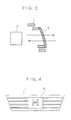
- Fig. 3 is a side view of another embodiment of the radar mounting structure according to the present invention.
- Fig. 4 is a front view of the front grille portion of the embodiment of Fig. 3.
- Fig. 5 is a side view of a conventional radar mounting structure.
- Fig. 6 is a front view of the front grille portion of the conventional structure.
- Figs. 1 and 2 are diagrams showing an embodiment of the radar mounting structure of the present invention.
- the embodiment relates to a general mounting structure in which emblem 2 is overlapped over a center area of front grille 1, and radar 3 is mounted inside the front grille 1.
- the front grille 1 and emblem 2 are made of resin 4 including bubbles and the amount of said bubbles is determined according to the desired attenuation of the radio waves.
- Radar 3 is provided in a center portion of the vehicle so as to detect an obstacle in front of the vehicle or to measure a distance to a vehicle ahead of the present vehicle, under the most optimal conditions.
- the bubbles included therein minimize the attenuation of the radio waves.
- Resin 4 including bubbles may be a foamed resin, or a hollow or honeycomb resin.
- the radio-wave transmitting and receiving operations can be performed with a sufficient radio-wave transmittance, regardless of the shape of the portion including the front grille 1 and emblem 2.
- the material of resin 4 itself (in which bubbles are not included) is not limited, that is, even a resin originally having insufficient radio-wave transmittance can be employed; thus, the flexibility for selecting a material can be improved, for example, weather-resistant or unfading materials, or various colored materials may be used.
- the emblem 2 may not be attached to the front grille 1, and in this case, the radio wave is transmitted or received by radar 3 only through the front grille 1.
- Figs. 3 and 4 show another embodiment according to the present invention.
- a center area of the front grille 1, facing radar 3, is opened and plate 5 is attached to the open area.
- This plate 5 is made of resin 4 including bubbles, and the plate also functions as an emblem. The radio-wave transmitting and receiving operations are performed through the plate 5.
- plate 5 may be separately attached to front grille 1, or the front grille 1 and plate 5 may be integrally formed using resin 4 including bubbles.
Landscapes
- Engineering & Computer Science (AREA)
- Computer Security & Cryptography (AREA)
- Radar, Positioning & Navigation (AREA)
- Remote Sensing (AREA)
- Mechanical Engineering (AREA)
- Radar Systems Or Details Thereof (AREA)
Applications Claiming Priority (2)
| Application Number | Priority Date | Filing Date | Title |
|---|---|---|---|
| JP11147030A JP2000304847A (ja) | 1999-04-16 | 1999-04-16 | レーダの車載構造 |
| JP14703099 | 1999-04-16 |
Publications (1)
| Publication Number | Publication Date |
|---|---|
| EP1045471A1 true EP1045471A1 (fr) | 2000-10-18 |
Family
ID=15420959
Family Applications (1)
| Application Number | Title | Priority Date | Filing Date |
|---|---|---|---|
| EP00303172A Withdrawn EP1045471A1 (fr) | 1999-04-16 | 2000-04-14 | Structure de montage de radar comprenant une résine contenant des bulles |
Country Status (2)
| Country | Link |
|---|---|
| EP (1) | EP1045471A1 (fr) |
| JP (1) | JP2000304847A (fr) |
Cited By (5)
| Publication number | Priority date | Publication date | Assignee | Title |
|---|---|---|---|---|
| EP0954052A3 (fr) * | 1998-05-02 | 2002-09-04 | DaimlerChrysler AG | Procédé de fabrication pour radome d' un radar de mesure de distance |
| FR2827080A1 (fr) * | 2001-07-06 | 2003-01-10 | Thales Sa | Dispositif pour cacher un radar representant un motif en volume, equipant notamment un vehicule et systeme de detection comportant un tel dispositif |
| US9828036B2 (en) | 2015-11-24 | 2017-11-28 | Srg Global Inc. | Active grille shutter system with integrated radar |
| US20170364086A1 (en) * | 2016-06-17 | 2017-12-21 | Toyota Motor Engineering & Manufacturing North America, Inc. | Sensor integration into existing vehicle structures |
| US20200358174A1 (en) * | 2017-12-28 | 2020-11-12 | Srg Global, Inc. | Microcellular foam body component for a vehicle radar system and its methods of manufacture |
Families Citing this family (5)
| Publication number | Priority date | Publication date | Assignee | Title |
|---|---|---|---|---|
| JP3958970B2 (ja) * | 2002-01-08 | 2007-08-15 | 本田技研工業株式会社 | 移動体用レーダー装置 |
| JP4821535B2 (ja) * | 2006-09-25 | 2011-11-24 | トヨタ自動車株式会社 | フロントグリル |
| JP2009031284A (ja) * | 2008-07-22 | 2009-02-12 | Toyota Motor Corp | 車輌のレーダー装置用カバー |
| JP6552326B2 (ja) * | 2015-08-07 | 2019-07-31 | 株式会社東海理化電機製作所 | 電波透過部品 |
| JP7063232B2 (ja) * | 2018-10-26 | 2022-05-09 | トヨタ自動車株式会社 | 車両前部構造 |
Citations (5)
| Publication number | Priority date | Publication date | Assignee | Title |
|---|---|---|---|---|
| EP0676648A1 (fr) * | 1994-04-07 | 1995-10-11 | Murata Manufacturing Co., Ltd. | Module émitteur-récepteur pour un moyen de transport |
| US5662293A (en) * | 1995-05-05 | 1997-09-02 | Hower; R. Thomas | Polyimide foam-containing radomes |
| DE19712098A1 (de) * | 1997-03-22 | 1998-05-14 | Bosch Gmbh Robert | Gehäuse für einen Radarsensor |
| EP0954052A2 (fr) * | 1998-05-02 | 1999-11-03 | DaimlerChrysler AG | Procédé de fabrication pour radome d' un radar de mesure de distance |
| FR2784235A1 (fr) * | 1998-09-25 | 2000-04-07 | Daimler Chrysler Ag | Partie de carenage situee a l'interieur du trajet du faisceau d'un radar |
-
1999
- 1999-04-16 JP JP11147030A patent/JP2000304847A/ja active Pending
-
2000
- 2000-04-14 EP EP00303172A patent/EP1045471A1/fr not_active Withdrawn
Patent Citations (5)
| Publication number | Priority date | Publication date | Assignee | Title |
|---|---|---|---|---|
| EP0676648A1 (fr) * | 1994-04-07 | 1995-10-11 | Murata Manufacturing Co., Ltd. | Module émitteur-récepteur pour un moyen de transport |
| US5662293A (en) * | 1995-05-05 | 1997-09-02 | Hower; R. Thomas | Polyimide foam-containing radomes |
| DE19712098A1 (de) * | 1997-03-22 | 1998-05-14 | Bosch Gmbh Robert | Gehäuse für einen Radarsensor |
| EP0954052A2 (fr) * | 1998-05-02 | 1999-11-03 | DaimlerChrysler AG | Procédé de fabrication pour radome d' un radar de mesure de distance |
| FR2784235A1 (fr) * | 1998-09-25 | 2000-04-07 | Daimler Chrysler Ag | Partie de carenage situee a l'interieur du trajet du faisceau d'un radar |
Cited By (8)
| Publication number | Priority date | Publication date | Assignee | Title |
|---|---|---|---|---|
| EP0954052A3 (fr) * | 1998-05-02 | 2002-09-04 | DaimlerChrysler AG | Procédé de fabrication pour radome d' un radar de mesure de distance |
| FR2827080A1 (fr) * | 2001-07-06 | 2003-01-10 | Thales Sa | Dispositif pour cacher un radar representant un motif en volume, equipant notamment un vehicule et systeme de detection comportant un tel dispositif |
| EP1280229A1 (fr) * | 2001-07-06 | 2003-01-29 | Thales | Dispositif pour cacher un radar représentant un motif en volume |
| US9828036B2 (en) | 2015-11-24 | 2017-11-28 | Srg Global Inc. | Active grille shutter system with integrated radar |
| US10137938B2 (en) | 2015-11-24 | 2018-11-27 | Srg Global Inc. | Active grille shutter system with integrated radar |
| US20170364086A1 (en) * | 2016-06-17 | 2017-12-21 | Toyota Motor Engineering & Manufacturing North America, Inc. | Sensor integration into existing vehicle structures |
| US10589694B2 (en) * | 2016-06-17 | 2020-03-17 | Toyota Motor Engineering & Manufacturing North America, Inc. | Sensor integration into existing vehicle structures |
| US20200358174A1 (en) * | 2017-12-28 | 2020-11-12 | Srg Global, Inc. | Microcellular foam body component for a vehicle radar system and its methods of manufacture |
Also Published As
| Publication number | Publication date |
|---|---|
| JP2000304847A (ja) | 2000-11-02 |
Similar Documents
| Publication | Publication Date | Title |
|---|---|---|
| EP1045471A1 (fr) | Structure de montage de radar comprenant une résine contenant des bulles | |
| JP2004312696A (ja) | ミリ波レーダおよびその製造方法 | |
| US8432309B2 (en) | Automotive radar system and method for using same | |
| EP0989028A2 (fr) | Rétroviseur extérieur pour véhicule avec antenne | |
| EP1548458A3 (fr) | Radar monté dans un véhicule | |
| EP0821429A3 (fr) | Antenne de véhicule | |
| JP2004361279A (ja) | 車載用レーダセンサシステム及び車載用レーダセンサ | |
| JP2001201557A (ja) | ミリ波レーダ | |
| US20050237250A1 (en) | Sensor for transmitting and receiving electromagnetic signals | |
| EP0896745B1 (fr) | Element d'antenne elastique | |
| CA2204295A1 (fr) | Couvercle pour cornet d'alimentation a antenne parabolique ou bloc a faible bruit concus l'un et l'autre pour recevoir des emissions en provenance de satellite | |
| JP2007074662A (ja) | ミリ波レーダ装置 | |
| EP0881624A3 (fr) | Capteur à ultrasons et son résonnateur ultrasonique | |
| AU2006302955A1 (en) | On a radome mounted GPS antenna assembly | |
| JPH11160426A (ja) | 車載レーダ装置 | |
| JP2005260659A (ja) | アンテナ付き車両用ウィンドシールド | |
| JP2006201047A (ja) | レーダ装置 | |
| JP2005142913A (ja) | 車載用レンズアンテナ | |
| US6433750B1 (en) | Reception antenna for radio wave marker | |
| CN115027372A (zh) | 具有外部环境传感器的车身结构 | |
| JP6738891B2 (ja) | バックミラーとアンテナを含む車両 | |
| GB2422960A (en) | Vehicle headliner antenna mounting structure | |
| US5940042A (en) | Windshield slot antenna for vehicle transmissions | |
| JP2008074352A (ja) | フロントグリル | |
| EP1095828A3 (fr) | Système de détection d'intrus pour un véhicule à moteur |
Legal Events
| Date | Code | Title | Description |
|---|---|---|---|
| PUAI | Public reference made under article 153(3) epc to a published international application that has entered the european phase |
Free format text: ORIGINAL CODE: 0009012 |
|
| AK | Designated contracting states |
Kind code of ref document: A1 Designated state(s): DE FR GB |
|
| AX | Request for extension of the european patent |
Free format text: AL;LT;LV;MK;RO;SI |
|
| 17P | Request for examination filed |
Effective date: 20010117 |
|
| AKX | Designation fees paid |
Free format text: DE FR GB |
|
| 17Q | First examination report despatched |
Effective date: 20020415 |
|
| STAA | Information on the status of an ep patent application or granted ep patent |
Free format text: STATUS: THE APPLICATION IS DEEMED TO BE WITHDRAWN |
|
| 18D | Application deemed to be withdrawn |
Effective date: 20041124 |