EP1045176A2 - Stützkörper für einen Wellendichtring - Google Patents
Stützkörper für einen Wellendichtring Download PDFInfo
- Publication number
- EP1045176A2 EP1045176A2 EP00106782A EP00106782A EP1045176A2 EP 1045176 A2 EP1045176 A2 EP 1045176A2 EP 00106782 A EP00106782 A EP 00106782A EP 00106782 A EP00106782 A EP 00106782A EP 1045176 A2 EP1045176 A2 EP 1045176A2
- Authority
- EP
- European Patent Office
- Prior art keywords
- support body
- sealing ring
- stop disc
- body according
- support section
- Prior art date
- Legal status (The legal status is an assumption and is not a legal conclusion. Google has not performed a legal analysis and makes no representation as to the accuracy of the status listed.)
- Granted
Links
- 238000007789 sealing Methods 0.000 claims abstract description 46
- 239000000463 material Substances 0.000 claims description 5
- 239000007769 metal material Substances 0.000 claims description 3
- 238000003860 storage Methods 0.000 claims description 3
- 230000004323 axial length Effects 0.000 claims description 2
- 230000036316 preload Effects 0.000 claims 1
- 238000004519 manufacturing process Methods 0.000 description 5
- 239000004810 polytetrafluoroethylene Substances 0.000 description 3
- 229920001343 polytetrafluoroethylene Polymers 0.000 description 3
- 239000013536 elastomeric material Substances 0.000 description 2
- 238000005520 cutting process Methods 0.000 description 1
- 238000003754 machining Methods 0.000 description 1
- 239000002861 polymer material Substances 0.000 description 1
- 238000007493 shaping process Methods 0.000 description 1
Images


Classifications
-
- F—MECHANICAL ENGINEERING; LIGHTING; HEATING; WEAPONS; BLASTING
- F16—ENGINEERING ELEMENTS AND UNITS; GENERAL MEASURES FOR PRODUCING AND MAINTAINING EFFECTIVE FUNCTIONING OF MACHINES OR INSTALLATIONS; THERMAL INSULATION IN GENERAL
- F16J—PISTONS; CYLINDERS; SEALINGS
- F16J15/00—Sealings
- F16J15/16—Sealings between relatively-moving surfaces
- F16J15/32—Sealings between relatively-moving surfaces with elastic sealings, e.g. O-rings
- F16J15/3268—Mounting of sealing rings
Definitions
- the invention relates to a support body for a shaft sealing ring.
- Such a support body is known from DE-OS 23 40 275.
- the Support body is designed as a sleeve-shaped mounting ring, the Outer contour of the mounting ring the inner circumferential side of the shaft sealing ring touched.
- the invention has for its object a support body for a Shaft seal to show that both the inner circumference of the Shaft sealing rings and one of its end faces as well as possible in front of the outside Protects influences and / or damage and also a simple Stripping the shaft seal from the support section by hand allows.
- a support body for a shaft seal provided, the support body - viewed in longitudinal section - in is essentially T-shaped and from one in the axial direction extending support section and one end face on the support section arranged stop disc, the support portion of at least one sealing lip of the shaft sealing ring under radial prestress is enclosable on the outer circumference, the bottom side or the End faces of the shaft sealing ring can be placed against the stop disk, wherein the stop disc has an outer diameter that is at least as is as large as the outer diameter of the shaft sealing ring and the Stop disk at least one disassembly recess for stripping of the shaft seal from the support section.
- the support body is advantageous in that both Inner circumferential side of the shaft sealing ring as well as one of its flat surfaces Reliably protected from external influences from the bottom or front are.
- Such a support body is particularly advantageous if the Shaft sealing ring a bulging in the direction of the space to be sealed PTFE sealing lip.
- Such sealing lips are very sensitive on external mechanical influences and should therefore be used during storage and / or transport are particularly protected.
- the is preferred Bottom side of the shaft seal can be placed on the stop disc.
- the disassembly recess and its arrangement in the stop disc is vitally important as the power to strip the Shaft sealing ring from the support section to the comparatively can attack the insensitive bottom side of the shaft seal.
- To the Stripping forces only act in the axial direction on the bottom side of the Shaft sealing rings, so that an undesirable deformation and / or Damage to the sealing lip, for example due to the radial Shaft sealing ring acting forces is excluded.
- the disassembly recess can - in the cross section of the stop disc considered - formed by a substantially groove-shaped depression and be open radially outwards.
- a mounting recess is particularly easy and inexpensive to manufacture. Does it exist Stop disc, for example made of a polymeric material, can groove-shaped recess during the manufacture of the stop disc in be shaped using a shaping tool.
- the stop disc consists of a metallic Material
- the groove-shaped recess can be formed or machining manufacturing processes are manufactured.
- the stop disc advantageously has two evenly Circumferentially distributed depressions on this is advantageous in that the evenly distributed arrangement the force to Stripping the shaft seal from the support section symmetrically on Shaft sealing ring attacks and therefore tilting of the shaft sealing ring related to the support body and an associated undesirable Deformation of the sealing lip is excluded.
- the Wells are designed to match.
- one such an embodiment is advantageous that assembly errors with respect to Angular assignment of the support body to the shaft sealing ring are reduced.
- the depressions can be in the circumferential direction of the stop disc be arcuate. It can be conveniently provided that the recesses the shape and size of a face on the Install the stop disk facing the side of the shaft sealing ring Show mark.
- the marking can, for example, by the Article number and / or the size of the supported shaft sealing ring his. Due to the above-described design of the support body the shaft sealing ring mounted on the support body is easily identified become.
- the support section preferably has an axial length which corresponds to the length of the Corresponding shaft seals in the same direction. Protection of the Shaft sealing ring against external influences and / or damage thereby further enlarged.
- the support section and the stop disc are preferably in one piece merging into one another and of uniform material.
- Prefers the support section and the stop disc are made of a polymer Material, for example polyetylene. With such a material is from Advantage that the production is inexpensive, the PTFE sealing lip is good the support section can slide and the support body is recycled after use can be.
- the support body described above is preferably used as a bearing and / or Transport protection ring for shaft seals.
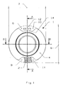
- Figure 1 is a view of a support body 1 according to the invention with an assembled shaft seal 2 shown.
- the support body 1 is is sleeve-shaped and has an annular stop disk 4 on, the radially on the inside integrally merging with the cylindrical support section 3 is formed.
- the stop disc 4 has an outer diameter 7, which is so in this embodiment is large, like the outer diameter 8 of the shaft sealing ring 2.
- the stop plate 4 in this embodiment two disassembly recesses 9 on the evenly distributed in the circumferential direction, each other are arranged opposite one another.
- the disassembly recesses 9 are formed as groove-shaped depressions 10, 11 which open radially outwards are. Through these recesses 10, 11 an axially acting force F brushes Shaft seal 2 from the support section 3.
- Force F is the manual force of a mechanic completely sufficient.
- 11 marks 12 can be read, for example specify the article number and / or the size of the shaft seal 2.
- FIG. 2 shows the section A-A from FIG. 1.
- the shaft seal 2 is designed as a radial shaft sealing ring with a PTFE sealing lip 5, the Sealing lip 5 the outer circumference of the support section 3 under radial Encloses bias.
- the support ring 13 of the shaft seal 2 is at least partially enclosed by elastomeric material, the elastomeric material facing the sealing lip 5 of the front Stop disc 4 touched.
- the outer diameter 8 of the shaft sealing ring 2 projects beyond the groove base 14 the first recess 10 in the radial direction.
- FIG. 3 shows section B-B from FIG. 1. This representation differs from the illustration in FIG. 2 in that the Cutting plane is offset by 90 °.
- the outer diameter 7, 8 of the stop washer 4 and shaft seal 2 are the same in this embodiment large.
Landscapes
- Engineering & Computer Science (AREA)
- General Engineering & Computer Science (AREA)
- Mechanical Engineering (AREA)
- Sealing With Elastic Sealing Lips (AREA)
Abstract
Description
- Figur 1
- eine Ansicht des Stützkörpers mit montiertem Wellendichtring aus Figur 2 von links,
- Figur 2
- einen Längsschnitt entlang der Linie A-A aus Figur 1,
- Figur 3
- einen Längsschnitt entlang der Linie B-B aus Figur 1.
Claims (11)
- Stützkörper (1) für einen Wellendichtring (2), wobei der Stützkörper (1) - im Längsschnitt betrachtet - im wesentlichen T-förmig ausgebildet ist und aus einem sich in axialer Richtung erstreckenden Stützabschnitt (3) und einer stirnseitig am Stützabschnitt (3) angeordneten Anschlagscheibe (4) besteht, wobei der Stützabschnitt (3) von zumindest einer Dichtlippe (5) des Wellendichtrings (2) unter radialer Vorspannung außenumfangsseitig umschließbar ist, wobei die Bodenseite (6) oder die Stirnseite des Wellendichtrings (2) an die Anschlagscheibe (4) anlegbar ist, wobei die Anschlagscheibe (4) einen Außendurchmesser (7) aufweist, der zumindest so groß ist, wie der Außendurchmesser (8) des Wellendichtrings (2) und wobei die Anschlagscheibe (4) zumindest eine Demontageausnehmung (9) zum Abstreifen des Wellendichtrings (2) vom Stützabschnitt (3) aufweist.
- Stützkörper nach Anspruch 1, dadurch gekennzeichnet, daß die Demontageausnehmung (9) - im Querschnitt der Anschlagscheibe (4) betrachtet - durch eine im wesentlichen nutförmige Vertiefung (10) gebildet und radial nach außen offen ist.
- Stützkörper nach einem der Ansprüche 1 oder 2, dadurch gekennzeichnet, daß die Anschlagscheibe (4) zwei gleichmäßig in Umfangsrichtung verteilte Vertiefungen (10, 11) aufweist.
- Stützkörper nach einem der Ansprüche 1 bis 3, dadurch gekennzeichnet, daß die Vertiefungen (10, 11) übereinstimmend ausgebildet sind.
- Stützkörper nach einem der Ansprüche 1 bis 4, dadurch gekennzeichnet, daß die Vertiefungen (10, 11) in Umfangsrichtung der Anschlagscheibe (4) bogenförmig ausgebildet sind.
- Stützkörper nach einem der Ansprüche 1 bis 5, dadurch gekennzeichnet, daß die Vertiefungen (10, 11) die Form und Größe einer stirnseitig auf der der Anschlagscheibe (4) zugewandten Seite des Wellendichtrings (2) angebrachten Markierung (12) aufweisen.
- Stützkörper nach einem der Ansprüche 1 bis 6, dadurch gekennzeichnet, daß der Stützabschnitt (3) eine axiale Länge aufweist, die der Länge des Wellendichtrings (2) in gleicher Richtung entspricht.
- Stützkörper nach einem der Ansprüche 1 bis 7, dadurch gekennzeichnet, daß der Stützabschnitt (3) und die Anschlagscheibe (4) einstückig ineinander übergehend und materialeinheitlich ausgebildet sind.
- Stützkörper nach einem der Ansprüche 1 bis 8, dadurch gekennzeichnet, daß der Stützabschnitt (3) und die Anschlagscheibe (4) aus einem polymeren Werkstoff bestehen.
- Stützkörper nach einem der Ansprüche 1 bis 8, dadurch gekennzeichnet, daß der Stützabschnitt (3) und die Anschlagscheibe (4) aus einem tiefziehbaren metallischen Werkstoff bestehen.
- Verwendung eines Stützkörpers (1) nach einem der Ansprüche 1 bis 10 als Lager- und/oder Transportschutzring.
Applications Claiming Priority (2)
| Application Number | Priority Date | Filing Date | Title |
|---|---|---|---|
| DE19916624A DE19916624C2 (de) | 1999-04-13 | 1999-04-13 | Stützkörper für einen Wellendichtring |
| DE19916624 | 1999-04-13 |
Publications (3)
| Publication Number | Publication Date |
|---|---|
| EP1045176A2 true EP1045176A2 (de) | 2000-10-18 |
| EP1045176A3 EP1045176A3 (de) | 2002-05-22 |
| EP1045176B1 EP1045176B1 (de) | 2003-11-12 |
Family
ID=7904376
Family Applications (1)
| Application Number | Title | Priority Date | Filing Date |
|---|---|---|---|
| EP00106782A Expired - Lifetime EP1045176B1 (de) | 1999-04-13 | 2000-03-30 | Stützkörper für einen Wellendichtring |
Country Status (3)
| Country | Link |
|---|---|
| EP (1) | EP1045176B1 (de) |
| BR (1) | BR0001590A (de) |
| DE (2) | DE19916624C2 (de) |
Cited By (2)
| Publication number | Priority date | Publication date | Assignee | Title |
|---|---|---|---|---|
| CN111536236A (zh) * | 2020-04-30 | 2020-08-14 | 清华大学 | 一种具有自发电功能的海洋用智能密封圈 |
| CN120646726A (zh) * | 2025-07-17 | 2025-09-16 | 常州市华耀智能科技有限公司 | 电动车生产用agv移动设备及其工作方法 |
Citations (1)
| Publication number | Priority date | Publication date | Assignee | Title |
|---|---|---|---|---|
| DE2340275B1 (de) | 1973-08-09 | 1974-10-17 | Ford Werke Ag | Transportschutz- und Montagering fuer Wellendichtringe |
Family Cites Families (4)
| Publication number | Priority date | Publication date | Assignee | Title |
|---|---|---|---|---|
| FR2573502B1 (fr) * | 1984-11-22 | 1987-02-13 | Hutchinson | Joint d'etancheite a levre pour arbre tournant |
| GB2199381A (en) * | 1986-12-23 | 1988-07-06 | Ford Motor Co | Seal installation |
| DE4141320C1 (en) * | 1991-12-14 | 1993-06-09 | Goetze Ag, 5093 Burscheid, De | Transport and assembly sleeve for shaft-sealing rings - has axial stop on tapered rearward part to prevent ring from slipping during transfer to shaft |
| DE19608975C2 (de) * | 1996-03-08 | 1999-04-15 | Cr Elastomere Gmbh | Transport- und Montagevorrichtung für einen Gehäuseverschlußdeckel |
-
1999
- 1999-04-13 DE DE19916624A patent/DE19916624C2/de not_active Expired - Fee Related
-
2000
- 2000-03-30 EP EP00106782A patent/EP1045176B1/de not_active Expired - Lifetime
- 2000-03-30 DE DE50004394T patent/DE50004394D1/de not_active Expired - Lifetime
- 2000-04-12 BR BR0001590-3A patent/BR0001590A/pt not_active Application Discontinuation
Patent Citations (1)
| Publication number | Priority date | Publication date | Assignee | Title |
|---|---|---|---|---|
| DE2340275B1 (de) | 1973-08-09 | 1974-10-17 | Ford Werke Ag | Transportschutz- und Montagering fuer Wellendichtringe |
Cited By (2)
| Publication number | Priority date | Publication date | Assignee | Title |
|---|---|---|---|---|
| CN111536236A (zh) * | 2020-04-30 | 2020-08-14 | 清华大学 | 一种具有自发电功能的海洋用智能密封圈 |
| CN120646726A (zh) * | 2025-07-17 | 2025-09-16 | 常州市华耀智能科技有限公司 | 电动车生产用agv移动设备及其工作方法 |
Also Published As
| Publication number | Publication date |
|---|---|
| DE19916624C2 (de) | 2001-05-17 |
| EP1045176B1 (de) | 2003-11-12 |
| EP1045176A3 (de) | 2002-05-22 |
| BR0001590A (pt) | 2001-01-02 |
| DE19916624A1 (de) | 2000-11-30 |
| DE50004394D1 (de) | 2003-12-18 |
Similar Documents
| Publication | Publication Date | Title |
|---|---|---|
| DE2215041C3 (de) | Sicherungs- und Dichtungselement | |
| EP1156241A2 (de) | Dichtmanschette, insbesondere für Einbauräume mit kleinen Abmessungen | |
| DE19627288A1 (de) | Lager mit Nullspiel | |
| DE3816915A1 (de) | L-foermige lageranordnung | |
| DE102004031302B4 (de) | Ringscheibe für ein Gleitlager | |
| DE3529316A1 (de) | Schwenkbare lagerung, insbesondere fuer lenksaeulen von kraftfahrzeugen | |
| DE3009810A1 (de) | Dichtung | |
| DE19754645A1 (de) | Dichtungseinsatz und Verfahren zu seiner Herstellung | |
| DE4222852A1 (de) | Wälzlagereinheit | |
| DE19728605A1 (de) | Stangen- oder Kolbendichtung | |
| DE3402366C2 (de) | ||
| DE2362285A1 (de) | Lager zum fixieren der axialen lage eines maschinenelementes | |
| DE8210552U1 (de) | Dichtungseinheit | |
| DE3914056C1 (en) | Roller bearing cage assembly - involves cage with protuberance on one end fitting into cavity in other end | |
| EP0611892A1 (de) | Bundzapfengelenk | |
| DE2463071C2 (de) | Lagereinheit | |
| DE602004006557T2 (de) | Kreuzgelenk mit einer Vorrichtung zum Abdichten der Lagerbüchse des Kreuzgelenkes | |
| EP1045176B1 (de) | Stützkörper für einen Wellendichtring | |
| DE2829792C2 (de) | ||
| DE3612420A1 (de) | Radialwellendichtring | |
| DE19834678A1 (de) | Abgedichtetes, Schwenkbewegungen ausführendes Gelenklager | |
| DE102013206579B4 (de) | Dichtungsanordnung mit einem Radialwellendichtring und einem zusätzlichen Dichtelement sowie Dichtelement für diese Dichtungsanordnung | |
| DE2943711A1 (de) | Lagerung, bestehend aus einem lagerinnenring, einem lageraussenring und einem lagergehaeuse | |
| DE2740302A1 (de) | Foerderrolle | |
| DE3838996C2 (de) |
Legal Events
| Date | Code | Title | Description |
|---|---|---|---|
| PUAI | Public reference made under article 153(3) epc to a published international application that has entered the european phase |
Free format text: ORIGINAL CODE: 0009012 |
|
| AK | Designated contracting states |
Kind code of ref document: A2 Designated state(s): AT BE CH CY DE DK ES FI FR GB GR IE IT LI LU MC NL PT SE |
|
| AX | Request for extension of the european patent |
Free format text: AL;LT;LV;MK;RO;SI |
|
| RAP1 | Party data changed (applicant data changed or rights of an application transferred) |
Owner name: CARL FREUDENBERG KG |
|
| PUAL | Search report despatched |
Free format text: ORIGINAL CODE: 0009013 |
|
| AX | Request for extension of the european patent |
Free format text: AL;LT;LV;MK;RO;SI |
|
| RIC1 | Information provided on ipc code assigned before grant |
Free format text: 7F 16J 15/10 A, 7F 16J 15/32 B |
|
| 17P | Request for examination filed |
Effective date: 20020412 |
|
| 17Q | First examination report despatched |
Effective date: 20020920 |
|
| AKX | Designation fees paid |
Designated state(s): DE FR GB IT |
|
| GRAH | Despatch of communication of intention to grant a patent |
Free format text: ORIGINAL CODE: EPIDOS IGRA |
|
| GRAS | Grant fee paid |
Free format text: ORIGINAL CODE: EPIDOSNIGR3 |
|
| GRAA | (expected) grant |
Free format text: ORIGINAL CODE: 0009210 |
|
| AK | Designated contracting states |
Kind code of ref document: B1 Designated state(s): DE FR GB IT |
|
| REG | Reference to a national code |
Ref country code: GB Ref legal event code: FG4D Free format text: NOT ENGLISH |
|
| REF | Corresponds to: |
Ref document number: 50004394 Country of ref document: DE Date of ref document: 20031218 Kind code of ref document: P |
|
| GBT | Gb: translation of ep patent filed (gb section 77(6)(a)/1977) |
Effective date: 20031215 |
|
| REG | Reference to a national code |
Ref country code: IE Ref legal event code: FG4D Free format text: GERMAN |
|
| REG | Reference to a national code |
Ref country code: IE Ref legal event code: FD4D |
|
| ET | Fr: translation filed | ||
| PLBE | No opposition filed within time limit |
Free format text: ORIGINAL CODE: 0009261 |
|
| STAA | Information on the status of an ep patent application or granted ep patent |
Free format text: STATUS: NO OPPOSITION FILED WITHIN TIME LIMIT |
|
| 26N | No opposition filed |
Effective date: 20040813 |
|
| PGFP | Annual fee paid to national office [announced via postgrant information from national office to epo] |
Ref country code: IT Payment date: 20060331 Year of fee payment: 7 |
|
| GBPC | Gb: european patent ceased through non-payment of renewal fee |
Effective date: 20070330 |
|
| PG25 | Lapsed in a contracting state [announced via postgrant information from national office to epo] |
Ref country code: GB Free format text: LAPSE BECAUSE OF NON-PAYMENT OF DUE FEES Effective date: 20070330 |
|
| PGFP | Annual fee paid to national office [announced via postgrant information from national office to epo] |
Ref country code: GB Payment date: 20060322 Year of fee payment: 7 |
|
| PG25 | Lapsed in a contracting state [announced via postgrant information from national office to epo] |
Ref country code: IT Free format text: LAPSE BECAUSE OF NON-PAYMENT OF DUE FEES Effective date: 20070330 |
|
| REG | Reference to a national code |
Ref country code: FR Ref legal event code: PLFP Year of fee payment: 17 |
|
| REG | Reference to a national code |
Ref country code: FR Ref legal event code: PLFP Year of fee payment: 18 |
|
| PGFP | Annual fee paid to national office [announced via postgrant information from national office to epo] |
Ref country code: FR Payment date: 20170323 Year of fee payment: 18 |
|
| PGFP | Annual fee paid to national office [announced via postgrant information from national office to epo] |
Ref country code: DE Payment date: 20170403 Year of fee payment: 18 |
|
| REG | Reference to a national code |
Ref country code: DE Ref legal event code: R119 Ref document number: 50004394 Country of ref document: DE |
|
| PG25 | Lapsed in a contracting state [announced via postgrant information from national office to epo] |
Ref country code: DE Free format text: LAPSE BECAUSE OF NON-PAYMENT OF DUE FEES Effective date: 20181002 |
|
| PG25 | Lapsed in a contracting state [announced via postgrant information from national office to epo] |
Ref country code: FR Free format text: LAPSE BECAUSE OF NON-PAYMENT OF DUE FEES Effective date: 20180331 |