EP1044867A1 - Body for an industrial vehicle, manufacturing process for such a body and industrial vehicle with such a body - Google Patents
Body for an industrial vehicle, manufacturing process for such a body and industrial vehicle with such a body Download PDFInfo
- Publication number
- EP1044867A1 EP1044867A1 EP00401055A EP00401055A EP1044867A1 EP 1044867 A1 EP1044867 A1 EP 1044867A1 EP 00401055 A EP00401055 A EP 00401055A EP 00401055 A EP00401055 A EP 00401055A EP 1044867 A1 EP1044867 A1 EP 1044867A1
- Authority
- EP
- European Patent Office
- Prior art keywords
- side walls
- profiles
- profile
- intended
- box
- Prior art date
- Legal status (The legal status is an assumption and is not a legal conclusion. Google has not performed a legal analysis and makes no representation as to the accuracy of the status listed.)
- Granted
Links
Images


Classifications
-
- B—PERFORMING OPERATIONS; TRANSPORTING
- B60—VEHICLES IN GENERAL
- B60P—VEHICLES ADAPTED FOR LOAD TRANSPORTATION OR TO TRANSPORT, TO CARRY, OR TO COMPRISE SPECIAL LOADS OR OBJECTS
- B60P1/00—Vehicles predominantly for transporting loads and modified to facilitate loading, consolidating the load, or unloading
- B60P1/04—Vehicles predominantly for transporting loads and modified to facilitate loading, consolidating the load, or unloading with a tipping movement of load-transporting element
- B60P1/28—Tipping body constructions
- B60P1/283—Elements of tipping devices
- B60P1/286—Loading buckets
-
- B—PERFORMING OPERATIONS; TRANSPORTING
- B62—LAND VEHICLES FOR TRAVELLING OTHERWISE THAN ON RAILS
- B62D—MOTOR VEHICLES; TRAILERS
- B62D33/00—Superstructures for load-carrying vehicles
- B62D33/02—Platforms; Open load compartments
Definitions
- the invention relates to a body for a vehicle. industrial, a method of manufacturing such a box and a industrial vehicle comprising such a body.
- Vehicles intended to transport material in loose, such as stones, sand or even seeds cereals or beets basically consist a body and a chassis with a running gear.
- the box can be mounted on the chassis, either in a fixed position or tilting and in particular tilting back and forth.
- the boxes used for such industrial vehicles can be seen as opposed to crates of vehicles carrying objects on pallets or large objects, like rigid units, the parts constituting the bottom and side walls of the box being integral one the other.
- the purpose of the present invention is to provide a box can be assembled from a small number of elements constituting the bottom and the side walls of the checkout.
- the object of the invention is achieved according to a design advantageously applying to cases essentially cylindrical and open upwards.
- the invention is also applicable to cases having a shape essentially parallelepiped.
- the object of the invention is achieved by a box for an industrial vehicle, with a bottom and two walls side, the bottom and the two side walls are provided, each with an edge intended for a junction between the bottom and respectively one and the other of the two walls side, of a profile allowing an assembly of the body by interlocking.
- the invention also relates to the following features considered in isolation or according to all their technically possible combinations.
- the element constituting the bottom of the body is provided at the two edges intended for the junction with the element constituting the corresponding side wall, of profiles presenting on the outside, intended to be opposite the profile of the corresponding wall, at least part in withdrawal.
- Each of the elements constituting a side wall is provided with the edge intended for the junction with the element constituting the bottom, of a profile having the interior side, intended to be opposite with the corresponding profile of the element constituting the bottom, at least one projecting part and complementary to the recessed part of the corresponding profile the bottom.
- the profiles of the elements constituting the walls side and the profiles of the element constituting the bottom are symmetrical about a longitudinal axis of the body.
- the profiles are extruded profiles.
- the profiles are attachments, welded to the corresponding face of the elements constituting the bottom and the side walls, intended to constitute the external face of the checkout.
- the profiles are parts integrated into the elements constituting the bottom and the side walls, each of these elements being an extruded element.
- the elements constituting the background and the side walls are aluminum elements.
- the profiles are arranged so that they can receive longitudinal members of a chassis of an industrial vehicle.
- the object of the invention is also achieved by a method of manufacturing a case having a bottom and two side walls, the bottom and the side walls being provided, each with an edge intended for a junction between the bottom and respectively one and the other of the two side walls, of a profile allowing assembly of the body by interlocking.
- this process comprises the stages arrange the side walls successively or simultaneously in an approximately parallel position to a vertical plane of symmetry of the body to be obtained, hang each of the side walls by their profile on the corresponding profile of the bottom and pivot the side walls outwards until the profiles fit together corresponding to the bottom and side walls.
- a industrial vehicle comprising a chassis and a body, the body comprising a bottom and two side walls provided each with an edge intended for a junction between the bottom and respectively one and the other of the two side walls, of a profile allowing assembly of the body by interlocking.
- the body can be mounted fixed or tilting from before backward.
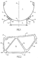
- a box 1 according to the invention comprises a bottom 2 and two side walls 3, 4.
- the bottom and the side walls are formed to form a fund essentially cylindrical.
- the body can have the form of a polyhedron or, as shown in the Figure 1, a round shape not necessarily circular.
- the bottom 2 which is concave upward in the position of use of the box, is provided on the face intended to constitute a part of the external face of the body, and more particularly to the two edges intended for constitute junctions with corresponding edges of elements forming the side walls, of two profiles 20 symmetrical about a vertical axis A of the body 1.
- These two profiles 20 can be obtained from the same extruded profile, cut to the required length and arranged in opposite directions to each other.
- the element constituting the bottom 2 is obtained by extrusion and that comprises, in an integrated or monobloc manner, the two profiles 20.
- the two elements constituting the left side wall and the side wall respectively right of the body, seen in the direction of its axis longitudinal, and which are also concave inwards of the body, are provided with the edge intended to be attached to the bottom 2, on the face intended to constitute a part of the face exterior of the body 1, of a profile 30, part of which is formed so that profiles 20 and 30 are complementary to be able to fit into each other.
- Each of the edges of the side walls intended to constitute the upper edges of the body 1 is provided with a profile 11, 12 arranged on the side intended to be oriented towards the inside of the body 1.
- Profile 20 is formed by an upper skin 21 intended to come into contact with the bottom 2, a skin lower 22, side skins 23, 24 and, inside the profile, sails 25, 26 forming acute angles with the skins 21 and 22 and ensuring the internal stability of the profile.
- the profile 20 has, in cross section, a shape of a polyhedron.
- the profile 20 also has a part 27 in shrinkage located near the junction of the upper skin 21 and lateral skin 23 intended to come into contact with a corresponding lateral skin of the profile 30. Part 27 is set back from the surface of the skin 21.
- Profile 20 also includes a recessed portion 27A and three grooves 28, 28A and 29.
- Part 27A is located close to the junction between the lateral skin 23 and the skin lower 22 and is recessed from the surface of the lateral skin 23.
- the groove 28 is located close to the junction between the lower skin 22 and lateral skin 23 and is practiced in the surface of the lower skin 22.
- the groove 28 is oriented approximately parallel to the plane of the web 25.
- the groove 28A is located close to the junction between the lateral skin 24 and upper skin 21.
- the groove 29 is located at the junction between the lower skin 22 and the skin lateral 24 and is oriented parallel, if not even in the plane defined by the veil 26.
- the profile 30 is constituted by an upper skin 31, a lower skin 32, an angular lateral skin or curved 33, 33A, a lateral skin 34 and two sails 35, 36.
- the sails 35, 36 form acute angles with the skins upper and lower 31.32 and provide internal stability of profile 30.
- the profile 30 also includes a part 37 in projecting from the lateral skin 34 intended to come into contact, during the assembly of profiles 20 and 30, with the skin 23 of profile 20.
- the shape of part 37 is complementary to that of part 27 of profile 20. This is first necessary for efficient assembly. Moreover, this provision allows, when the box is loaded, to distribute the resulting stress at the junction, over the weld and on the junction between parts 27 and 37. Without this layout, the weld alone should withstand the stress
- Profile 30 also includes two parts 38, 39 extending approximately in planes parallel to upper skin shots 31 but recessed from the surface of the latter.
- Profile 30 is provided close to the junction of the lateral skin 34 with lower skin 32, of part 37A projecting from the lateral skin 34.
- the shape of the part 37A is complementary to the form of part 27A of the profile 20.
- each of the walls side 3, 4 is hooked to the corresponding edge of the bottom 2 and pivoted outward, i.e. away from the axis vertical symmetrical A of box 1, until the corresponding profiles fit together. Then the welds necessary are made to secure the walls side 3, 4 with the bottom 2.
- side members 7 a chassis C of an industrial vehicle or elements having for the function of forming a support on the side members of a chassis of a tilting body vehicle can be fixed in the notches 28A or 29 of the profiles 20.
- the choice is determined by the lateral distance between the side members, depending on the axle type.
- profiles forming skirts 13, 14 of an industrial vehicle can be fixed in the notches 28 of the profiles 20 of the bottom 2.
- Figure 5 shows a semi-trailer, as of nonlimiting application example, with a case 1 according to the invention.
- the body 1 is also provided with a wall front 5 and a rear overhead door 6.
- Figure 5 also represents the arrangement of an undercarriage 8 to two axles and a jack 9 for tilting the body 1 back and forth.
Landscapes
- Engineering & Computer Science (AREA)
- Transportation (AREA)
- Mechanical Engineering (AREA)
- Chemical & Material Sciences (AREA)
- Combustion & Propulsion (AREA)
- Body Structure For Vehicles (AREA)
- Forklifts And Lifting Vehicles (AREA)
- Vehicle Step Arrangements And Article Storage (AREA)
Abstract
Description
L'invention concerne une caisse pour un véhicule industriel, un procédé de fabrication d'une telle caisse et un véhicule industriel comportant une telle caisse.The invention relates to a body for a vehicle. industrial, a method of manufacturing such a box and a industrial vehicle comprising such a body.
Les véhicules destinés à transporter de la matière en vrac, tel que des pierres, du sable ou encore des graines de céréales ou des betteraves, sont constituées essentiellement d'une caisse et d'un châssis avec un train roulant. La caisse peut être montée sur le châssis, soit en position fixe, soit basculant et notamment basculant d'avant en arrière.Vehicles intended to transport material in loose, such as stones, sand or even seeds cereals or beets, basically consist a body and a chassis with a running gear. The box can be mounted on the chassis, either in a fixed position or tilting and in particular tilting back and forth.
Les caisses utilisées pour de tels véhicules industriels peuvent être considérées, par opposition à des caisses de véhicules transportant des objets sur palette ou des grands objets, comme des unités rigides, les parties constituant le fond et les parois latérales de la caisse étant solidaires l'une de l'autre.The boxes used for such industrial vehicles can be seen as opposed to crates of vehicles carrying objects on pallets or large objects, like rigid units, the parts constituting the bottom and side walls of the box being integral one the other.
Toutefois, lors de la conception d'une caisse qui doit être obtenue par assemblage d'un fond avec deux parois latérales, se pose la question du type d'assemblage et des détails de conception qui en découlent. La réponse à cette question peut varier selon la forme de la caisse et le matériau utilisé pour sa réalisation.However, when designing a box that must be obtained by assembling a bottom with two walls side, the question arises of the type of assembly and design details derived therefrom. The answer to this question may vary depending on the shape of the case and the material used for its realization.
Le but de la présente invention est de proposer une caisse pouvant être assemblées à partir d'un petit nombre d'éléments constituant le fond et les parois latérales de la caisse.The purpose of the present invention is to provide a box can be assembled from a small number of elements constituting the bottom and the side walls of the checkout.
Le but de l'invention est atteint selon une conception s'appliquant avantageusement à des caisses essentiellement cylindriques et ouvertes vers le haut. Toutefois, l'invention est également applicable à des caisses ayant une forme essentiellement parallélépipédique.The object of the invention is achieved according to a design advantageously applying to cases essentially cylindrical and open upwards. However, the invention is also applicable to cases having a shape essentially parallelepiped.
Ainsi, le but de l'invention est atteint par une caisse pour un véhicule industriel, avec un fond et deux parois latérales, dont le fond et les deux parois latérales sont pourvus, chacun à un bord destiné à une jonction entre le fond et respectivement l'une et l'autre des deux parois latérales, d'un profil permettant un assemblage de la caisse par emboítement.Thus, the object of the invention is achieved by a box for an industrial vehicle, with a bottom and two walls side, the bottom and the two side walls are provided, each with an edge intended for a junction between the bottom and respectively one and the other of the two walls side, of a profile allowing an assembly of the body by interlocking.
Lorsque les éléments constituant le fond et les parois latérales de la caisse sont assemblés par emboítement, ils sont solidarisés par soudage ou par tout autre procédé approprié.When the elements constituting the bottom and the walls sides of the body are assembled by interlocking, they are joined by welding or any other process appropriate.
L'invention concerne également les caractéristiques ci-après considérées isolément ou selon toutes leurs combinaisons techniquement possibles.The invention also relates to the following features considered in isolation or according to all their technically possible combinations.
L'élément constituant le fond de la caisse est pourvu aux deux bords destinés à la jonction avec l'élément constituant la paroi latérale correspondante, de profils présentant du côté extérieur, destiné à être en regard avec le profil de la paroi correspondante, au moins une partie en retrait.The element constituting the bottom of the body is provided at the two edges intended for the junction with the element constituting the corresponding side wall, of profiles presenting on the outside, intended to be opposite the profile of the corresponding wall, at least part in withdrawal.
Chacun des éléments constituant une paroi latérale est pourvu au bord destiné à la jonction avec l'élément constituant le fond, d'un profil présentant du côté intérieur, destiné à être en regard avec le profil correspondant de l'élément constituant le fond, au moins une partie en saillie et complémentaire à la partie en retrait du profil correspondant du fond.Each of the elements constituting a side wall is provided with the edge intended for the junction with the element constituting the bottom, of a profile having the interior side, intended to be opposite with the corresponding profile of the element constituting the bottom, at least one projecting part and complementary to the recessed part of the corresponding profile the bottom.
Les profils des éléments constituant les parois latérales et les profils de l'élément constituant le fond sont symétriques par rapport à un axe longitudinal de la caisse.The profiles of the elements constituting the walls side and the profiles of the element constituting the bottom are symmetrical about a longitudinal axis of the body.
Les profils sont des profils extrudés.The profiles are extruded profiles.
Les profils sont des pièces rapportées, soudées sur la face correspondante des éléments constituant le fond et les parois latérales, destinés à constituer la face extérieure de la caisse.The profiles are attachments, welded to the corresponding face of the elements constituting the bottom and the side walls, intended to constitute the external face of the checkout.
Les profils sont des pièces intégrées dans les éléments constituant le fond et les parois latérales, chacun de ces éléments étant un élément extrudé.The profiles are parts integrated into the elements constituting the bottom and the side walls, each of these elements being an extruded element.
Plus particulièrement, les éléments constituant le fond et les parois latérales sont des éléments en aluminium. More particularly, the elements constituting the background and the side walls are aluminum elements.
Les profils sont disposés de façon à pouvoir recevoir des longerons d'un châssis d'un véhicule industriel.The profiles are arranged so that they can receive longitudinal members of a chassis of an industrial vehicle.
Le but de l'invention est également atteint par un procédé de fabrication d'une caisse ayant un fond et deux parois latérales, le fond et les parois latérales étant pourvus, chacun à un bord destiné à une jonction entre le fond et respectivement l'une et l'autre des deux parois latérales, d'un profil permettant un assemblage de la caisse par emboítement.The object of the invention is also achieved by a method of manufacturing a case having a bottom and two side walls, the bottom and the side walls being provided, each with an edge intended for a junction between the bottom and respectively one and the other of the two side walls, of a profile allowing assembly of the body by interlocking.
Conformément à l'invention, ce procédé comprend les étapes disposer les parois latérales successivement ou simultanément dans une position approximativement parallèle à un plan de symétrie vertical de la caisse à obtenir, accrocher chacune des parois latérales par leur profil sur le profil correspondant du fond et pivoter le parois latérales vers l'extérieur jusqu'à emboítement des profils correspondants du fond et des parois latérales.According to the invention, this process comprises the stages arrange the side walls successively or simultaneously in an approximately parallel position to a vertical plane of symmetry of the body to be obtained, hang each of the side walls by their profile on the corresponding profile of the bottom and pivot the side walls outwards until the profiles fit together corresponding to the bottom and side walls.
Le but de l'invention est également atteint par un véhicule industriel comportant un châssis et une caisse, la caisse comprenant un fond et deux parois latérales pourvus chacun à un bord destiné à une jonction entre le fond et respectivement l'une et l'autre des deux parois latérales, d'un profil permettant un assemblage de la caisse par emboítement.The object of the invention is also achieved by a industrial vehicle comprising a chassis and a body, the body comprising a bottom and two side walls provided each with an edge intended for a junction between the bottom and respectively one and the other of the two side walls, of a profile allowing assembly of the body by interlocking.
La caisse peut être montée fixe ou basculante d'avant en arrière.The body can be mounted fixed or tilting from before backward.
D'autres caractéristiques et avantages de l'invention
ressortiront de la description d'un mode de réalisation en
référence aux dessins. Dans ces dessins:
Une caisse 1 selon l'invention comprend un fond 2 et
deux parois latérales 3, 4. Le fond et les parois latérales sont
formées de façon à constituer une caisse essentiellement
cylindrique. En section transversale, la caisse peut avoir la
forme d'un polyèdre ou, comme cela est représenté sur la
Figure 1, une forme ronde non nécessairement circulaire.A
Le fond 2, qui est concave vers le haut dans la
position d'utilisation de la caisse, est pourvu sur la face
destinée à constituer une partie de la face extérieure de la
caisse, et plus particulièrement aux deux bords destinés à
constituer des jonctions avec des bords correspondants des
éléments formant les parois latérales, de deux profils 20
symétriques par rapport à un axe vertical A de la caisse 1.
Ces deux profils 20 peuvent être obtenus à partir d'un même
profilé extrudé, coupés à la longueur nécessaire et disposés
dans des sens opposés l'un par rapport à l'autre.The
Toutefois, il est également concevable que l'élément
constituant le fond 2 soit obtenu par extrusion et qu'il
comporte, de façon intégrée ou monobloc, les deux profils 20.However, it is also conceivable that the element
constituting the
De façon comparable à la conception de l'élément
formant le fond 2, les deux éléments constituant
respectivement la paroi latérale gauche et la paroi latérale
droite de la caisse, vu dans la direction de son axe
longitudinal, et qui sont également concaves vers l'intérieur
de la caisse, sont pourvus au bord destiné à être rattaché au
fond 2, sur la face destinée à constituer une partie de la face
extérieure de la caisse 1, d'un profil 30 dont une partie est
formée de façon à ce que les profils 20 et 30 soient
complémentaire pour pouvoir être emboítés l'un dans l'autre.Comparable to the design of the element
forming the
Chacun des bords des parois latérales destinées à
constituer les bords supérieurs de la caisse 1 est pourvu d'un
profilé 11, 12 disposé sur la face destinée à être orientée
vers l'intérieur de la caisse 1. Each of the edges of the side walls intended to
constitute the upper edges of the
Le profil 20 est formé par une peau supérieure 21
destinée à venir en contact avec le fond 2, une peau
inférieure 22, des peaux latérales 23, 24 et, à l'intérieur du
profil, de voiles 25, 26 formant des angles aigus avec les
peaux 21 et 22 et assurant la stabilité interne du profil. Le
profil 20 présente, en section transversale, une forme d'un
polyèdre.
Le profil 20 présente par ailleurs une partie 27 en
retrait située proche de la jonction de la peau supérieure 21
et de la peau latérale 23 destinée à venir en contact avec
une peau correspondante latérale du profil 30. La partie 27
est en retrait par rapport à la surface de la peau 21.The
Le profil 20 comprend également une partie en retrait
27A et trois rainures 28, 28A et 29. La partie 27A est située
proche de la jonction entre la peau latérale 23 et la peau
inférieure 22 et est en retrait par rapport à la surface de la
peau latérale 23.
La rainure 28 est située proche de la jonction entre la
peau inférieure 22 et la peau latérale 23 et est pratiquée
dans la surface de la peau inférieure 22. La rainure 28 est
orientée approximativement parallèlement au plan du voile
25. La rainure 28A est située proche de la jonction entre la
peau latérale 24 et la peau supérieure 21. La rainure 29 est
située à la jonction entre la peau inférieure 22 et la peau
latérale 24 et est orientée parallèlement, sinon même dans le
plan défini par le voile 26.The
Le profil 30 est constitué par une peau supérieure 31,
une peau inférieure 32, une peau latérale angulaire ou
courbée 33, 33A, une peau latérale 34 et deux voiles 35, 36.
Les voiles 35, 36 forment des angles aigus avec les peaux
supérieure et inférieure 31,32 et assurent la stabilité interne
du profil 30.The
Le profil 30 comprend par ailleurs une partie 37 en
saillie par rapport à la peau latérale 34 destinée à venir en
contact, lors de l'assemblage des profils 20 et 30, avec la
peau 23 du profil 20. La forme de la partie 37 est
complémentaire à celle de la partie 27 du profil 20. Ceci est
d'abord nécessaire pour un assemblage efficace. De plus,
cette disposition permet, lorsque la caisse est chargée, de
répartir la contrainte résultante à la jonction, sur la soudure
et sur la jonction entre les parties 27 et 37. Sans cette
disposition, la soudure devrait seule supporter la contrainteThe
Le profil 30 comprend également deux parties 38, 39
s'étendant approximativement dans des plans parallèles aux
plans de la peau supérieure 31, mais en retrait par rapport à
la surface de cette dernière.
Le profil 30 est pourvu proche de la jonction de la
peau latérale 34 avec la peau inférieure 32, d'une partie 37A
en saillie par rapport à la peau latérale 34. La forme de la
partie 37A est complémentaire à la forme de la partie 27A du
profil 20.
L'assemblage des parois latérales 3, 4 de la caisse 1
avec le fond 2 est effectué en approchant les profils 20 et 30
de façon que s'accroche d'abord la partie 37 du profil 30
dans la partie 27 du profil 20, et que les deux profils 20, 30
sont pivotés l'un par rapport à l'autre, à la manière d'une
charnière, de façon que la partie 37A s'approche et vienne en
contact avec la partie 27A du profil 20. Deux profils 20, 30
ainsi assemblés sont représentés sur la Figure 4.The assembly of the side walls 3, 4 of the
Lorsque le fond 2 et les parois latérales 3, 4 sont
obtenus par extrusion, ils comprennent, de façon intégrée, le
ou les profils correspondants. La manoeuvre d'assemblage
décrite ci-avant, est alors exécutée de manière
correspondante. En d'autres termes, chacune des parois
latérales 3, 4 est accrochée au bord correspondant du fond 2
et pivotée vers l'extérieur, c'est-à-dire en s'éloignant de l'axe
symétrique vertical A de la caisse 1, jusqu'à ce que les
profils correspondants s'emboítent. Ensuite, les soudages
nécessaires sont effectués pour solidariser les parois
latérales 3, 4 avec le fond 2. When the
Lorsque la caisse 1 est assemblée, des longerons 7
d'un châssis C d'un véhicule industriel ou des éléments ayant
pour fonction de constituer un appui sur des longerons d'un
châssis d'un véhicule à caisse basculante peuvent être fixés
dans les encoches 28A ou 29 des profils 20. Le choix est
déterminé par la distance latérale entre les longerons,
fonction du type d'essieu. De même, des profilés formant des
jupes 13, 14 d'un véhicule industriel peuvent être fixés dans
les encoches 28 des profils 20 du fond 2.When the
La Figure 5 représente une semi-remorque, à titre
d'exemple d'application non limitatif, avec une caisse 1 selon
l'invention. La caisse 1 est pourvue, par ailleurs, d'une paroi
avant 5 et d'une porte basculante arrière 6. La Figure 5
représente aussi la disposition d'un train roulant 8 à deux
essieux et un vérin 9 permettant de basculer la caisse 1
d'avant en arrière.Figure 5 shows a semi-trailer, as
of nonlimiting application example, with a
Les signes de référence insérés après les caractéristiques techniques mentionnées dans les revendications, ont pour seul but de faciliter la compréhension de ces dernières, et n'en limitent aucunement la portée.The reference signs inserted after the technical characteristics mentioned in the claims are intended only to facilitate the understanding of these, and in no way limit them the scope.
Claims (11)
Applications Claiming Priority (2)
| Application Number | Priority Date | Filing Date | Title |
|---|---|---|---|
| FR9904846A FR2792276B1 (en) | 1999-04-16 | 1999-04-16 | BODY FOR AN INDUSTRIAL VEHICLE, METHOD FOR MANUFACTURING SUCH A BODY AND INDUSTRIAL VEHICLE COMPRISING SUCH A BODY |
| FR9904846 | 1999-04-16 |
Publications (2)
| Publication Number | Publication Date |
|---|---|
| EP1044867A1 true EP1044867A1 (en) | 2000-10-18 |
| EP1044867B1 EP1044867B1 (en) | 2004-07-14 |
Family
ID=9544535
Family Applications (1)
| Application Number | Title | Priority Date | Filing Date |
|---|---|---|---|
| EP00401055A Expired - Lifetime EP1044867B1 (en) | 1999-04-16 | 2000-04-14 | Body for an industrial vehicle, manufacturing process for such a body and industrial vehicle with such a body |
Country Status (5)
| Country | Link |
|---|---|
| EP (1) | EP1044867B1 (en) |
| AT (1) | ATE270995T1 (en) |
| DE (1) | DE60012071D1 (en) |
| FR (1) | FR2792276B1 (en) |
| TN (1) | TNSN00079A1 (en) |
Cited By (2)
| Publication number | Priority date | Publication date | Assignee | Title |
|---|---|---|---|---|
| EP1435309A1 (en) * | 2002-12-20 | 2004-07-07 | General Trailers France | Body for an industrial vehicle, manufacturing process for such a body and industrial vehicle with such a body |
| CN105416146A (en) * | 2015-12-02 | 2016-03-23 | 广州电力机车有限公司 | Packing box of dump truck |
Citations (4)
| Publication number | Priority date | Publication date | Assignee | Title |
|---|---|---|---|---|
| GB1431764A (en) * | 1972-04-11 | 1976-04-14 | Cravens Homalloy Sheffield Ltd | Load-carrying bodies |
| US5454620A (en) * | 1991-01-18 | 1995-10-03 | Ultra Lite Manufacturing, Inc. | Stressed-skin cargo carrier |
| DE29606451U1 (en) * | 1996-04-09 | 1996-07-18 | Heggemann Udo | Self-supporting vehicle floor for road vehicle bodies |
| US5765906A (en) * | 1995-10-04 | 1998-06-16 | Honda Giken Kogyo Kabushiki Kaisha | Vehicle body structure made of extruded members |
-
1999
- 1999-04-16 FR FR9904846A patent/FR2792276B1/en not_active Expired - Fee Related
-
2000
- 2000-04-14 TN TNTNSN00079A patent/TNSN00079A1/en unknown
- 2000-04-14 AT AT00401055T patent/ATE270995T1/en not_active IP Right Cessation
- 2000-04-14 EP EP00401055A patent/EP1044867B1/en not_active Expired - Lifetime
- 2000-04-14 DE DE60012071T patent/DE60012071D1/en not_active Expired - Lifetime
Patent Citations (4)
| Publication number | Priority date | Publication date | Assignee | Title |
|---|---|---|---|---|
| GB1431764A (en) * | 1972-04-11 | 1976-04-14 | Cravens Homalloy Sheffield Ltd | Load-carrying bodies |
| US5454620A (en) * | 1991-01-18 | 1995-10-03 | Ultra Lite Manufacturing, Inc. | Stressed-skin cargo carrier |
| US5765906A (en) * | 1995-10-04 | 1998-06-16 | Honda Giken Kogyo Kabushiki Kaisha | Vehicle body structure made of extruded members |
| DE29606451U1 (en) * | 1996-04-09 | 1996-07-18 | Heggemann Udo | Self-supporting vehicle floor for road vehicle bodies |
Cited By (3)
| Publication number | Priority date | Publication date | Assignee | Title |
|---|---|---|---|---|
| EP1435309A1 (en) * | 2002-12-20 | 2004-07-07 | General Trailers France | Body for an industrial vehicle, manufacturing process for such a body and industrial vehicle with such a body |
| CN105416146A (en) * | 2015-12-02 | 2016-03-23 | 广州电力机车有限公司 | Packing box of dump truck |
| CN105416146B (en) * | 2015-12-02 | 2018-03-13 | 广州电力机车有限公司 | A kind of capacity of the tipping body |
Also Published As
| Publication number | Publication date |
|---|---|
| FR2792276B1 (en) | 2003-06-13 |
| EP1044867B1 (en) | 2004-07-14 |
| TNSN00079A1 (en) | 2002-05-30 |
| ATE270995T1 (en) | 2004-07-15 |
| DE60012071D1 (en) | 2004-08-19 |
| FR2792276A1 (en) | 2000-10-20 |
Similar Documents
| Publication | Publication Date | Title |
|---|---|---|
| CA2559370C (en) | Multipurpose and evolutive road trailer | |
| EP1547909A1 (en) | structural element for a vehcile comprising two metallic bodies and a polymer reinforcement member binding the two bodies, and vehicle comprising such an element | |
| EP3678879B1 (en) | Mechanism for a motor vehicle trunk with two opening panels | |
| EP3096999A1 (en) | Body shell structure of a motor vehicle with reinforcements for distributing forces linked to a rear shock absorber of the vehicle | |
| WO1999059856A1 (en) | Side wall for railway car and corresponding railway car body | |
| FR3066466A1 (en) | STORAGE BIN FOR ASSEMBLY ON A BODY STRUCTURE OF A MOTOR VEHICLE. | |
| FR2986489A1 (en) | Bearing structure i.e. cradle, for supporting connections on ground of automobile, has connection part positioned and attached laterally to cross-section of profile through external surface that is coupled to external surface of profile | |
| EP1044867B1 (en) | Body for an industrial vehicle, manufacturing process for such a body and industrial vehicle with such a body | |
| FR2932433A1 (en) | Ready-to-mount elements assembly for forming horse van, has panels constituting trimming of cell, and doors received by rear frame of structure of cell, where structure is provided with posts, side bars and bows and is in form of framework | |
| FR2985494A1 (en) | Opening panel e.g. tail gate, and reinforcing elements assembly for motor vehicle, has reinforcing elements and connecting elements forming continuous frame when reinforcing elements and opening panel are connected | |
| FR2922509A1 (en) | Passenger compartment side for body of motor vehicle, has preformed skin whose lower fixation wing is assembled to reinforcement spar via auxiliary spar parallelly extending on predetermined transverse distance away from bottom edge of spar | |
| EP0466588B1 (en) | Demountable isothermic cell for light delivery van | |
| EP3597514B1 (en) | Extension with a frame, in particular intended for the production of a panel | |
| WO2015110740A1 (en) | Body structure of a motor vehicle with reinforcements for distributing the forces linked to a rear shock absorber of the vehicle | |
| FR2872787A1 (en) | Bulk material transporting/storing skip, has lateral walls terminated with bottom wall near connection zone by stiffening section, where walls are made of distinct sheet metal and concavity of lateral walls directs loads along bottom wall | |
| FR2871428A1 (en) | Structural unit for use in motor vehicle, has channel receiving connecting part of reinforcement part, and opening at periphery of frame by end opening to allow connecting part to cover cross piece | |
| EP1435309B1 (en) | Body for an industrial vehicle, manufacturing process for such a body and industrial vehicle with such a body | |
| FR3072638B1 (en) | ARRANGEMENT OF A VEHICLE BODY AND METHOD OF MAKING SAME | |
| EP3377391B1 (en) | Improved profile for the structure of a land vehicle for public passenger transport, structure, and vehicle comprising such a profile | |
| FR2800693A1 (en) | Motor vehicle body frame unit made in one piece with supports for ends of lengthwise members on either side of centre section | |
| EP3377389B1 (en) | Multi-function profile for the structure of a land vehicle for public passenger transport, structure, and vehicle comprising such a profile | |
| EP3377390B1 (en) | Optimised structure for a land vehicle for public passenger transport, and vehicle comprising such a structure | |
| FR2535666A1 (en) | Profiled part for the rack panel of a utility vehicle, use of such a profiled part | |
| EP0926000B1 (en) | Van-type trailer for transport of horses | |
| FR2736014A1 (en) | Pre-assembled tilting frame for motor vehicle, |
Legal Events
| Date | Code | Title | Description |
|---|---|---|---|
| PUAI | Public reference made under article 153(3) epc to a published international application that has entered the european phase |
Free format text: ORIGINAL CODE: 0009012 |
|
| AK | Designated contracting states |
Kind code of ref document: A1 Designated state(s): AT BE CH CY DE DK ES FI FR GB GR IE IT LI LU MC NL PT SE |
|
| AX | Request for extension of the european patent |
Free format text: AL;LT;LV;MK;RO;SI |
|
| 17P | Request for examination filed |
Effective date: 20010418 |
|
| AKX | Designation fees paid |
Free format text: AT BE CH CY DE DK ES FI FR GB GR IE IT LI LU MC NL PT SE |
|
| 17Q | First examination report despatched |
Effective date: 20021213 |
|
| GRAP | Despatch of communication of intention to grant a patent |
Free format text: ORIGINAL CODE: EPIDOSNIGR1 |
|
| GRAS | Grant fee paid |
Free format text: ORIGINAL CODE: EPIDOSNIGR3 |
|
| GRAA | (expected) grant |
Free format text: ORIGINAL CODE: 0009210 |
|
| AK | Designated contracting states |
Kind code of ref document: B1 Designated state(s): AT BE CH CY DE DK ES FI FR GB GR IE IT LI LU MC NL PT SE |
|
| PG25 | Lapsed in a contracting state [announced via postgrant information from national office to epo] |
Ref country code: IT Free format text: LAPSE BECAUSE OF FAILURE TO SUBMIT A TRANSLATION OF THE DESCRIPTION OR TO PAY THE FEE WITHIN THE PRESCRIBED TIME-LIMIT;WARNING: LAPSES OF ITALIAN PATENTS WITH EFFECTIVE DATE BEFORE 2007 MAY HAVE OCCURRED AT ANY TIME BEFORE 2007. THE CORRECT EFFECTIVE DATE MAY BE DIFFERENT FROM THE ONE RECORDED. Effective date: 20040714 Ref country code: NL Free format text: LAPSE BECAUSE OF FAILURE TO SUBMIT A TRANSLATION OF THE DESCRIPTION OR TO PAY THE FEE WITHIN THE PRESCRIBED TIME-LIMIT Effective date: 20040714 Ref country code: AT Free format text: LAPSE BECAUSE OF FAILURE TO SUBMIT A TRANSLATION OF THE DESCRIPTION OR TO PAY THE FEE WITHIN THE PRESCRIBED TIME-LIMIT Effective date: 20040714 Ref country code: IE Free format text: LAPSE BECAUSE OF FAILURE TO SUBMIT A TRANSLATION OF THE DESCRIPTION OR TO PAY THE FEE WITHIN THE PRESCRIBED TIME-LIMIT Effective date: 20040714 Ref country code: GB Free format text: LAPSE BECAUSE OF FAILURE TO SUBMIT A TRANSLATION OF THE DESCRIPTION OR TO PAY THE FEE WITHIN THE PRESCRIBED TIME-LIMIT Effective date: 20040714 Ref country code: FI Free format text: LAPSE BECAUSE OF FAILURE TO SUBMIT A TRANSLATION OF THE DESCRIPTION OR TO PAY THE FEE WITHIN THE PRESCRIBED TIME-LIMIT Effective date: 20040714 |
|
| REG | Reference to a national code |
Ref country code: GB Ref legal event code: FG4D Free format text: NOT ENGLISH |
|
| REG | Reference to a national code |
Ref country code: CH Ref legal event code: EP |
|
| REF | Corresponds to: |
Ref document number: 60012071 Country of ref document: DE Date of ref document: 20040819 Kind code of ref document: P |
|
| REG | Reference to a national code |
Ref country code: IE Ref legal event code: FG4D Free format text: FRENCH |
|
| PG25 | Lapsed in a contracting state [announced via postgrant information from national office to epo] |
Ref country code: GR Free format text: LAPSE BECAUSE OF FAILURE TO SUBMIT A TRANSLATION OF THE DESCRIPTION OR TO PAY THE FEE WITHIN THE PRESCRIBED TIME-LIMIT Effective date: 20041014 Ref country code: SE Free format text: LAPSE BECAUSE OF FAILURE TO SUBMIT A TRANSLATION OF THE DESCRIPTION OR TO PAY THE FEE WITHIN THE PRESCRIBED TIME-LIMIT Effective date: 20041014 Ref country code: DK Free format text: LAPSE BECAUSE OF FAILURE TO SUBMIT A TRANSLATION OF THE DESCRIPTION OR TO PAY THE FEE WITHIN THE PRESCRIBED TIME-LIMIT Effective date: 20041014 |
|
| PG25 | Lapsed in a contracting state [announced via postgrant information from national office to epo] |
Ref country code: DE Free format text: LAPSE BECAUSE OF FAILURE TO SUBMIT A TRANSLATION OF THE DESCRIPTION OR TO PAY THE FEE WITHIN THE PRESCRIBED TIME-LIMIT Effective date: 20041015 |
|
| PG25 | Lapsed in a contracting state [announced via postgrant information from national office to epo] |
Ref country code: ES Free format text: LAPSE BECAUSE OF FAILURE TO SUBMIT A TRANSLATION OF THE DESCRIPTION OR TO PAY THE FEE WITHIN THE PRESCRIBED TIME-LIMIT Effective date: 20041025 |
|
| NLV1 | Nl: lapsed or annulled due to failure to fulfill the requirements of art. 29p and 29m of the patents act | ||
| GBV | Gb: ep patent (uk) treated as always having been void in accordance with gb section 77(7)/1977 [no translation filed] |
Effective date: 20040714 |
|
| REG | Reference to a national code |
Ref country code: IE Ref legal event code: FD4D |
|
| PG25 | Lapsed in a contracting state [announced via postgrant information from national office to epo] |
Ref country code: CY Free format text: LAPSE BECAUSE OF FAILURE TO SUBMIT A TRANSLATION OF THE DESCRIPTION OR TO PAY THE FEE WITHIN THE PRESCRIBED TIME-LIMIT Effective date: 20050414 Ref country code: LU Free format text: LAPSE BECAUSE OF NON-PAYMENT OF DUE FEES Effective date: 20050414 |
|
| PG25 | Lapsed in a contracting state [announced via postgrant information from national office to epo] |
Ref country code: MC Free format text: LAPSE BECAUSE OF NON-PAYMENT OF DUE FEES Effective date: 20050430 Ref country code: LI Free format text: LAPSE BECAUSE OF NON-PAYMENT OF DUE FEES Effective date: 20050430 Ref country code: BE Free format text: LAPSE BECAUSE OF NON-PAYMENT OF DUE FEES Effective date: 20050430 Ref country code: CH Free format text: LAPSE BECAUSE OF NON-PAYMENT OF DUE FEES Effective date: 20050430 |
|
| PLBE | No opposition filed within time limit |
Free format text: ORIGINAL CODE: 0009261 |
|
| STAA | Information on the status of an ep patent application or granted ep patent |
Free format text: STATUS: NO OPPOSITION FILED WITHIN TIME LIMIT |
|
| 26N | No opposition filed |
Effective date: 20050415 |
|
| BERE | Be: lapsed |
Owner name: *GENERAL TRAILERS FRANCE Effective date: 20050430 |
|
| REG | Reference to a national code |
Ref country code: CH Ref legal event code: PL |
|
| PG25 | Lapsed in a contracting state [announced via postgrant information from national office to epo] |
Ref country code: FR Free format text: LAPSE BECAUSE OF NON-PAYMENT OF DUE FEES Effective date: 20051230 |
|
| REG | Reference to a national code |
Ref country code: FR Ref legal event code: ST Effective date: 20051230 |
|
| BERE | Be: lapsed |
Owner name: *GENERAL TRAILERS FRANCE Effective date: 20050430 |
|
| PG25 | Lapsed in a contracting state [announced via postgrant information from national office to epo] |
Ref country code: PT Free format text: LAPSE BECAUSE OF NON-PAYMENT OF DUE FEES Effective date: 20041214 |