EP3377390B1 - Optimised structure for a land vehicle for public passenger transport, and vehicle comprising such a structure - Google Patents
Optimised structure for a land vehicle for public passenger transport, and vehicle comprising such a structure Download PDFInfo
- Publication number
- EP3377390B1 EP3377390B1 EP16805009.4A EP16805009A EP3377390B1 EP 3377390 B1 EP3377390 B1 EP 3377390B1 EP 16805009 A EP16805009 A EP 16805009A EP 3377390 B1 EP3377390 B1 EP 3377390B1
- Authority
- EP
- European Patent Office
- Prior art keywords
- ring
- face
- body structure
- rings
- profile
- Prior art date
- Legal status (The legal status is an assumption and is not a legal conclusion. Google has not performed a legal analysis and makes no representation as to the accuracy of the status listed.)
- Active
Links
- 238000003466 welding Methods 0.000 claims description 19
- 230000002787 reinforcement Effects 0.000 claims description 7
- 229910000831 Steel Inorganic materials 0.000 claims description 6
- 239000010959 steel Substances 0.000 claims description 6
- 238000004519 manufacturing process Methods 0.000 description 8
- 238000004146 energy storage Methods 0.000 description 5
- 230000007797 corrosion Effects 0.000 description 4
- 238000005260 corrosion Methods 0.000 description 4
- 238000001962 electrophoresis Methods 0.000 description 4
- 239000000463 material Substances 0.000 description 4
- 239000007787 solid Substances 0.000 description 4
- 238000000926 separation method Methods 0.000 description 3
- 230000007423 decrease Effects 0.000 description 2
- 238000011031 large-scale manufacturing process Methods 0.000 description 2
- 230000003647 oxidation Effects 0.000 description 2
- 238000007254 oxidation reaction Methods 0.000 description 2
- 229920000049 Carbon (fiber) Polymers 0.000 description 1
- 208000027418 Wounds and injury Diseases 0.000 description 1
- XAGFODPZIPBFFR-UHFFFAOYSA-N aluminium Chemical compound [Al] XAGFODPZIPBFFR-UHFFFAOYSA-N 0.000 description 1
- 229910052782 aluminium Inorganic materials 0.000 description 1
- 238000013459 approach Methods 0.000 description 1
- 239000004917 carbon fiber Substances 0.000 description 1
- 230000006378 damage Effects 0.000 description 1
- 208000014674 injury Diseases 0.000 description 1
- 238000009434 installation Methods 0.000 description 1
- 230000003014 reinforcing effect Effects 0.000 description 1
- 238000007789 sealing Methods 0.000 description 1
- 230000003313 weakening effect Effects 0.000 description 1
Images


Classifications
-
- B—PERFORMING OPERATIONS; TRANSPORTING
- B62—LAND VEHICLES FOR TRAVELLING OTHERWISE THAN ON RAILS
- B62D—MOTOR VEHICLES; TRAILERS
- B62D31/00—Superstructures for passenger vehicles
- B62D31/02—Superstructures for passenger vehicles for carrying large numbers of passengers, e.g. omnibus
Definitions
- the present invention relates to a framework optimized for a land passenger transport vehicle, in particular of the bus or tram-bus type. It also relates to a land passenger transport vehicle, in particular an electric vehicle, comprising such a framework.
- the field of the invention is the field of land vehicles for public transport, in particular electric, of bus, coach or tram-bus type.
- bus One of the most popular means of public transport is the bus, because its installation does not require any specific infrastructure, of the railroad type for example.
- electric buses are making their appearance, encouraged both by raising awareness among users but also by administrative incentive measures encouraging the purchase and use of electric vehicles. We are also witnessing the appearance and development of tram-buses. The number of buses, electric or not, is constantly increasing.
- the current buses are built by assembling numerous parts ultimately forming the framework of the bus which is the main element of the bus.
- the framework is then dressed, then equipped.
- the bus is built progressively, by adding parts, such as bars or tubes, individually one after the other.
- the fixing of an individual part to the others is carried out by bolting or by welding.
- bus frames and more generally of land public transport vehicles on the road, does not allow large-scale production while allowing design flexibility for the vehicle.
- the current frameworks for vehicles transit systems are complex and time-consuming to manufacture. Finally, they have a habitability / mechanical strength ratio which is not satisfactory.
- the DE 10 2006 022259 A1 discloses a framework for land transport vehicle with all the features of the preamble of independent claim 1.
- An object of the present invention is to remedy these drawbacks.
- Another object of the invention is to propose a framework for land public transport vehicle suitable for large-scale production while allowing design flexibility for said vehicle.
- Another object of the invention is to provide a framework for land transport vehicle less complex and faster to manufacture.
- the invention makes it possible to achieve at least one of these aims by a framework for a land vehicle for the public transport of passengers, in particular on the road, and in particular of the bus type, characterized in that it comprises at least two rigid rings going around said frame in the width direction, around a passenger compartment defined by said frame.
- the invention provides a frame formed by rigid rings which are connected together by connecting elements.
- Such a framework allows faster and industrializable manufacturing.
- such a framework allows a flexible design of vehicles, because it is possible to add or remove one or more rigid rings to modify the length of the vehicle and thus customize the vehicle on demand and according to need. It is for example possible to design vehicles of different lengths. It is also possible to change the position and the number of doors or wheel arches.
- the rigid rings allow increased mechanical strength compared to other architectures currently used.
- a “tram-bus” designates a land-based electric public transport vehicle mounted on wheels and which is recharged at each station, so as not to require heavy infrastructure such as rails, catenaries, on the roads.
- Such an electric vehicle is recharged at each station by means of charging elements of the station and a connector connecting said vehicle to said station.
- the assembly plane is in an area that is both less effortless and that does not interfere with the arrangement on the frame of elements such as openings.
- the framework according to the invention can comprise a number of rigid rings of between 2 and 15, and in particular between 7 and 12.
- At least one, in particular each, ring can define a vertical plane perpendicular to at least one, in particular each, of the side walls of said framework.
- the perfectly vertical arrangement of the rings makes it possible to increase the mechanical strength, especially in relation to vertical loads, exerted on the roof or the roof of the public transport vehicle, for example by air conditioners or storage modules for energy arranged on the pavilion.
- the rings can be aligned one behind the other, each ring defining a plane parallel to the plane defined by at least one other ring, in particular by each of the other rings.
- At least one, in particular each, ring can have a narrower width at its upper end compared to the rest of said ring, and in particular compared to a lower end of said ring.
- Such a shape makes it possible to further increase the mechanical strength and the resistance to vertical forces exerted on the frame according to the invention.
- At least one, in particular each, lateral edge of at least one, in particular of each, ring can be curved or curved towards the inside of said ring at an upper part of said ring.
- each ring may have lateral edges which are substantially vertical at the level of the lower part and of the central part of said ring, and which curl towards one another at the level of the upper part of said ring.
- At least one, in particular each, corner of at least one, in particular of each, ring can be rounded so that said corner does not have a sharp part, which presents less risk of injury to operators during of the manufacture of said frame.
- At least one, in particular each, ring can be formed, at least in part, by assembling several parts.
- At least one, in particular each, of said parts can advantageously be connected / connected to at least one other part by end assembly or by a male-female connection.
- Such an end or male-female assembly makes it possible to reduce the total weight of the frame because it makes it possible to limit, or even eliminate, the duplicates and / or the overlapping of the parts during their assembly.
- the end assembly makes it possible to increase the space in the passenger compartment, compared to an architecture in which the parts forming the framework overlap, at least partially.
- the assembly of at least two parts of a ring can be carried out by butt welding, or by bolting, or even by a male female connection.
- each, ring may comprise at least one form or interconnection piece, called a node, male or female, for connecting said ring with another ring or another piece of said framework by a connection of male-female type.
- Such a male or female node makes it possible to reduce the total weight of the frame because it makes it possible to limit, or even eliminate, the duplicates and / or the overlapping of the parts during their assembly.
- At least one, in particular each, ring may have a substantially flat upper edge.
- Such a flat edge makes it possible to design a framework whose upper wall is substantially flat and does not constitute wind resistance.
- At least one, in particular each, ring may have an upper edge folded / curved towards the inside of said ring, in particular from each of its upper corners.
- Such an upper edge, curved / folded towards the inside of the ring can be used to form, with at least one other similar or identical ring, a housing or a compartment at the level of an upper wall of said framework.
- a housing can for example be used to receive an energy storage module, an air conditioner, etc.
- Such a housing can, in addition or alternatively, form (or be used to arrange) a lateral or longitudinal technical conduit.
- Such a ring makes it possible to design a framework, the upper wall of which comprises a housing or a compartment, while comprising a flat outer surface which does not constitute wind resistance.
- the distances between two consecutive rings, taken two by two can be identical or variable.
- two consecutive rings can touch each other and even serve as a connection interface between two separately produced frame modules.
- two consecutive rings can be arranged side by side to locally increase the rigidity of the frame.
- two rings can be arranged at a distance from each other, for example in areas of least effort.
- At least one, in particular each, ring can comprise a vertical plane of symmetry passing through the center of said ring determined in the direction of the width of said ring.
- Such a ring makes it possible to further simplify the architecture of the frame and its manufacture.
- At least one, in particular each, ring can be made, at least in part, of steel.
- each ring can also be treated against corrosion, for example, by cataphoresis.
- At least one ring can be made of carbon fibers, aluminum, etc.
- the framework according to the invention may also comprise at least one fixing part, known as a reinforcement leg, bearing on a vertical lateral upright of said ring and forming support for a higher upright, or a upper edge, forming said ring.
- at least one fixing part known as a reinforcement leg
- Such a reinforcement leg reinforces the ring, in particular at an upper corner of said ring, so as to better resist the vertical loads applying to said ring.
- Such an upper section may include a face, called an outer face, lying between said first face and said second face and, in use, on the outer side with respect to the passenger compartment.
- Said external face may comprise at least one surface, called a fixing surface, for fixing an external covering element, forming a hook in said external face, towards the inside of said upper profile.
- Such a fixing surface allows easier and ergonomic fixing of an external covering element.
- At least one of said first and second faces can be offset with respect to the other of said faces in a direction perpendicular to said one face, so that said other face stops before said one face in said direction.
- the upper profile can be full or hollow.
- At least one of said faces can be offset with respect to the other of said faces in a direction perpendicular to said one face, so that said other face stops before, and at a distance from said one face in said perpendicular direction.
- each lower profile may include a face, called an inner face, lying between said first face and said second face, and in use, on the passenger compartment side, said inner face being curved towards the inside of said lower profile.
- the living area within the frame according to the invention is improved.
- the lower profile can be hollow or solid.
- a land vehicle for public transport in particular on the road, comprising a framework according to the invention.
- Such a vehicle can be a hybrid vehicle or an electric vehicle.
- Such a vehicle can be a bus, a coach, or a tram-bus.
- the vehicle according to the invention may comprise at least one housing, arranged in the thickness of the upper wall, and designed to receive at least one electrical energy storage module, in particular rechargeable.
- variants of the invention comprising only a selection of characteristics described below, isolated from the other characteristics described, if this selection of characteristics is sufficient to confer a technical advantage or to differentiate the invention from of the prior art.
- This selection includes at least one characteristic, preferably functional, without structural details, or with only a part of the structural details if this part is only sufficient to confer a technical advantage or to differentiate the invention from the state of the prior art.
- the FIGURE 1 is a schematic representation of a vehicle according to the invention.
- the vehicle 100 shown in the FIGURE 1 is an electric bus comprising a front wall 102, two longitudinal side walls 104 and 106, a rear wall 108, an upper wall 110 and a lower wall 112.
- the electric bus comprises one or more electric motors (not shown), modules 114, called rear, for storing electrical energy, arranged on the side of the rear wall 108.
- the bus 100 also comprises modules 116, called upper, for storing electrical energy, arranged in a housing arranged in the upper wall 110 of the bus 100.
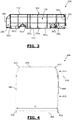
- the FIGURE 2 is a schematic representation of an example frame according to the invention in an isometric view.
- the FIGURE 3 is a schematic representation of the skeleton of the FIGURE 2 according to a side view.
- the framework 200 of the FIGURE 2 is formed by nine rings 202 1 -202 9 , the ring 202 1 being on the side of the front wall 102 of the frame 200 and the ring 202 9 being on the side of the rear wall 108 of the frame 200 .
- the framework 200 comprises, arranged in the thickness of the upper wall 110, four compartments 204 each provided for accommodating a rechargeable electric energy storage module supplying the electric motor (s) (not shown) of the vehicle.
- the frame 200 further comprises, arranged in the thickness of the rear wall 108, one or more compartments 206 each provided to accommodate a rechargeable electric energy storage module supplying the electric motor or motors (not shown) of the vehicle.
- the rings 202 1 -202 9 are arranged aligned longitudinally, parallel to each other.
- the distances between two rings 202 taken two by two are variable.
- the rings 202 2 and 202 3 are glued one to the other. the other.
- the rings 202 6 and 202 7 are separated by a smaller distance compared to that separating the rings 202 4 and 202 5 .
- Each ring 202 defines a vertical plane perpendicular to each of the side walls 104 and 106, to the upper wall 110 and to the lower wall 112 of the frame.
- the vertical plane defined by a ring 202 is substantially parallel to the front wall 102 and to the rear wall 108 of the frame 200.
- each ring 202 is made of steel previously treated by cataphoresis against corrosion, for example by assembling hollow tubes.
- Each ring 202 can be produced by assembling parts with a male-female type connection.
- the rings 202 can have identical or different shapes and dimensions.
- the rings 202 are connected to each other by longitudinal, vertical or crossed elements, parts or profiles, so as to produce a one-piece and rigid frame.
- the FIGURE 4 is a schematic representation of a first example of a ring that can be used in a frame according to the invention.
- the ring 400 shown in the FIGURE 4 can be any of the rings 202 1 -202 3 , 202 8 and 202 9 of the framework 200 shown in the FIGURES 2-3 .
- the ring 400 comprises two vertical edges 402 and 404, also called uprights, defining the lateral sides of the ring 400.
- the lateral edge 402 is for example on the side of the lateral wall 104 of the framework 200 of the FIGURES 2-3 and the side edge 404 is on the side of the side wall 106 of the frame 200 of the FIGURES 2-3 .
- the ring 400 also includes a lower edge 406, also called the lower spar, defining the bottom or the bottom side of the ring 400.
- the bottom edge 406 is substantially horizontal and is, for example, on the side of the bottom wall 112 of the framework 200 of FIGURES 2-3 .
- the lower edge 406 also defines the lower end of the ring 400.
- the ring 400 also includes an upper edge 408, also called upper spar, defining the top, or the top side of the ring 400.
- the top edge 408 is substantially horizontal and is, for example, on the side of the top wall. 110 of the framework 200 of FIGURES 2-3 .
- the upper edge 408 defines the upper end of the ring 400.
- connection between the lateral edges 402 and 404 and the lower edge 406 is carried out by welding, either directly of the parts producing said edges between them, or by means of interconnection elements 410, also called lower longitudinal sections, arranged at the level of the lower corners, and on which the parts forming said edges are welded.
- interconnection elements 410 also called lower longitudinal sections, arranged at the level of the lower corners, and on which the parts forming said edges are welded.
- male-female type interconnection elements can also be used.
- connection between the side edges 402 and 404 and the upper edge 408 can be made by welding, either directly of the parts making said edges together, or of one or more intermediate elements.
- the lateral edges 402 and 404 and the upper edge 408 are connected together, by welding on interconnection elements 412, also called upper longitudinal sections, arranged at each of the upper corners of the ring. .
- interconnection elements 412 also called upper longitudinal sections, arranged at each of the upper corners of the ring.
- male-female type interconnection elements can also be used.
- the ring 400 represented on the FIGURE 4 is divided into two parts: an upper part 414 and a lower part 416, separated from each other in a horizontal plane, materialized by the line 418, closer to the upper edge 408 than to the lower edge 406. Such a separation facilitates the manufacture of the frame while weakening the said frame as little as possible, in terms of mechanical strength.
- the upper part 414 and the lower part 416 are fixed together by an end connection, that is to say without overlapping.
- the lateral edges, or uprights, vertical 402 and 404 are mutually parallel and substantially rectilinear.
- the lateral edges, or uprights, vertical 402 and 404 are curved or curved towards one another, that is to say towards the inside of the ring 400.
- the width of the ring 400 decreases upwards, that is to say when one approaches the upper edge 408.
- the ring 400 has a minimum width at the edge, or spar, upper 408.
- the four corners of the ring 400 of the FIGURE 4 are rounded.
- the parts for making the vertical uprights 402 and 404, and the horizontal beams 406 and 408, of the ring 400 may be bars or sections of steel, hollow or solid.
- the ring 400 has a substantially flat and horizontal upper edge making it possible to produce a frame or a vehicle whose upper wall 110 is substantially flat, thus constituting no resistance to wind.
- the FIGURE 5 is a schematic representation of a second example of a ring that can be used in a frame according to the invention.
- the ring 500 shown in the FIGURE 5 can be any one of the rings 202 4 -202 7 of the framework 200 represented on the FIGURES 2-3 .
- the ring 500 represented on the FIGURE 5 , includes all the elements of the ring 400 of the FIGURE 4 .
- the ring 500 comprises, at its upper end, a connecting piece, or spar, 502 forming a curved path towards the inside of the ring 500, from each of the upper corners of the ring .
- the connecting piece 502 connects the lateral edges 402 and 404 of the ring 500 to each other. This connecting piece somehow forms a second upper edge, seen from the inside of the ring 500, and curved inwards of the ring 500.
- the connecting piece 502 forms a support for defining, with at least one other similar or identical ring, a housing or a compartment at the level of the upper wall of the frame or of the vehicle, such as for example the housing 204 of the framework 200 of FIGURES 2-3 .
- Each ring may include elements for interconnecting a ring with a longitudinal or vertical piece or else a cross piece of the framework.
- the FIGURE 6a gives a first example of an interconnection piece which can be used in the framework according to the invention, for example in the framework of FIGURES 2-3 .
- Exhibit 602 shown in the FIGURE 6a comes in the form of a "T".
- Each end of the "T” has a female housing that can accommodate the male end of a room.
- the part 602 is positioned at the plane 418 of separation of the upper 414 and lower 416 parts of a ring.
- Two of the opposite female ends of the “T”, on either side of the part 602, receive the male ends of the upright 402.
- the third female end of the “T” receives a longitudinal part 604 connecting the ring with another ring or with another part of the frame.
- the part 602 comprises a narrowing, or removal, of material 612, in particular practiced in a rounded or circular manner, at the level of each of the corners formed by the branches of the "T" between them. These corners corresponding to stress concentration zones and such a shrinking of material increases the mechanical strength of the connecting piece 602.
- the FIGURE 6b gives a second example of an interconnection piece which can be used in the frame according to the invention, for example in the frame of FIGURES 2-3 .
- Exhibit 606 shown in the FIGURE 6b is in the form of a “+” cross.
- Each end of the cross "+” has a female housing that can accommodate the male end of a room.
- the part 606 is positioned at the plane 418 of separation of the upper 414 and lower 416 parts of a ring.
- Two of the opposite female ends of the cross “+”, on either side of the part 606, receive the male ends of the upright 402.
- the other two opposite female ends of the cross "+” Accommodate two longitudinal parts 608 and 610 connecting the ring with another ring or another part of the frame, in the same direction and in opposite directions.
- the part 606 comprises a narrowing, or removal, of material 612, in particular practiced in a rounded or circular manner, at each of the corners formed by the branches of the "+" between them. These corners corresponding to stress concentration zones and such a shrinking of material increases the mechanical strength of the connecting piece 606.
- FIGURE 7 is a partial schematic representation of another example of a nonlimiting connection that can be implemented in the framework according to the invention.
- FIGURE 7 gives a representation of the connection between the upper spar 408, and possibly of the spar 502, with the vertical lateral upright 402.
- a fixing piece 702 called a reinforcement leg, is used to reinforce the fixing of the vertical lateral upright 402 with the spar 408, and possibly with the spar 502.
- the reinforcing leg 702 is fixed to the vertical upright 402, for example by welding, screwing or bolting.
- the upper beams 408 and 502 are fixed to the reinforcement leg 702 by screwing, welding or bolting.
- Such a reinforcement leg 702 can be used for each connection point between the upper side member (s) and a vertical post making up a ring.
- Such a reinforcement leg can be used for each ring, the latter comprising or not a spar 502.
- FIGURE 8 is a representation of an example of non-limiting assembly of an upper part and a lower part of a ring, for example rings 400 and 500, which can be implemented in a frame according to the invention.
- the upper part 414 of a ring 400 or 500 is housed in a first profile 802, the section of which is in the shape of a "U".
- This first profile 802 is fixed to the upper part of the ring, for example by welding.
- the lower part 416 of the ring 400 or 500 is housed in a second profile 804, the section of which is in the shape of a "U".
- This second profile 804 is fixed to the lower part 416, for example by welding.
- the first profile 802 and the second profile 804 are arranged back-to-back or head to tail.
- the profiles 802 and 804 are then fixed to each other by a plurality of bolts 806.
- At least one of the profiles 802 and 804 may be common to several rings arranged along the frame for fixing the upper part and the lower part of several rings.
- FIGURE 9 is a schematic representation, in section, of a nonlimiting exemplary embodiment of a profile that can be used in a ring of a frame according to the invention, for example rings 400 and 500.
- Profile 900 shown in the FIGURE 9 can be profile 412 of FIGURES 4 and 5 .
- Profile 900 is of closed section, and can be hollow or solid. In the rest of the request, the profile 900 can be called the upper profile.
- the upper profile 900 comprises a first face 902 for fixing the longitudinal members 408 and 502 of the ring, a second face 904 for fixing the upright 402 of the ring, an external face 906 being on the opposite side inside the ring and an inner face 908 located on the side of the interior of said ring.
- the external face 906 comprises a surface 910 for fixing a covering element of the side wall, such as for example a glazed element 916.
- the fixing surface 910 of the covering element forms a notch in the external face 906, towards the inside of profile 900, so that the covering element, once fixed on the outer face 906, is in continuity with the outer face 906 or does not protrude from the outer face 906.
- the profile 900 may comprise at its outer face 906 a surface 918 for fixing a covering element 920 of the upper wall, such as a cover element or a sealing wall.
- the profile 900 can also comprise at its external face 906, a surface 922, not covered by a covering element and intended to form a part of the external surface of the vehicle, in particular at the upper corner of the vehicle.
- a covering element not covered by a covering element and intended to form a part of the external surface of the vehicle, in particular at the upper corner of the vehicle.
- the surface 922 then being a surface visible from the exterior of the vehicle (part of the bodywork / vehicle skin).
- first face 902 is offset from the second face 904 in a direction perpendicular to the first face 902, so that the second face 904 stops before and at a distance from the first face 902 in said perpendicular direction.
- the second face 904 is offset with respect to the first face 902 in a direction perpendicular to the second face 904, so that the first face 902 stops before and at a distance from the second face 904 in said perpendicular direction.
- the longitudinal members 408, 502 and the upright 402 are fixed, at the end, to the profile 900 directly without the use of an additional fixing element, for example by welding.
- the upper profile 900 shown in the FIGURE 9 is made by folding and welding a steel sheet 3mm thick, or between 1mm and 5mm.
- the welding line is preferably positioned at the interior face 908, on which no element is fixed.
- Profile 900 is preferably treated by cataphoresis against oxidation and corrosion.
- FIGURE 10 is a schematic representation, in section, of a nonlimiting exemplary embodiment of a profile that can be used in a ring of a frame according to the invention, for example rings 400 and 500.
- Profile 1000 shown in the FIGURE 10 can be profile 410 of FIGURES 4 and 5 .
- Profile 1000 has a closed section, and can be hollow or solid. In the rest of the request, the profile 1000 can be called the lower profile.
- the lower profile 1000 comprises a first face 1002 for fixing the beam 406, a second face 1004 for fixing the upright 402, an outer face 1006 located on the opposite side inside the ring 400 or 500 and an inner face 1008 opposite the outer face 1006.
- the inner face 1008 is curved towards the profile 1000. It is formed by two parts 1010 1 and 1010 2 , perpendicular to each other. Part 1010 1 is on the side of the first face 1002 and is perpendicular to the first face 1002 and parallel to the second face 1004. Part 1010 2 is on the side of the second face 1004 and is perpendicular to the second face 1004 and parallel to the first face 1002.
- the width and the height of the ring are optimized, which makes it possible to increase the width and the height of the passenger compartment.
- the first face 1002 is perpendicular to the second face 1004.
- first face 1002 is offset from the second face 1004 in a direction perpendicular to the first face 1002, so that the second face 1004 stops before and at a distance from the first face 1002 in said perpendicular direction.
- the second face 1004 is offset with respect to the first face 1002 in a direction perpendicular to the second face 1004, so that the first face 1002 stops before and at a distance from the second face 1004 in said perpendicular direction.
- the first face 1002 is perpendicular to the direction defined by the beam 406.
- the beam 406 is fixed to the profile 1000 at the end, that is to say without overlapping with any part of the profile 1000.
- the second face 1004 is perpendicular to the direction defined by the upright 402.
- the upright 402 is fixed to the end profile 1000, that is to say without overlapping with any part of the profile 1000.
- the upright 402 and the beam 406 are fixed to the profile 1000 directly without the use of an additional fixing element.
- the beam 406 and the upright 402 are fixed to the profile 1000 by welding.
- the lower profile 1000 shown in the FIGURE 10 is made by folding and welding a steel sheet 3mm thick, or between 1mm and 5mm.
- the welding line is, for example, positioned at the second face 1004. Alternatively, the welding line can be positioned at the first face 1002.
- Profile 1000 is treated by cataphoresis against oxidation and corrosion.
- the number of storage modules is not limited to four, and corresponds to the maximum of energy storage modules depending in particular on the weight of the vehicle and the range deemed sufficient for the operation of the vehicle.
- the invention is not limited to buses and can for example be applied to coaches, tram-buses and other public transport vehicles, in particular on land, and even more particularly on the road.
Landscapes
- Engineering & Computer Science (AREA)
- Chemical & Material Sciences (AREA)
- Combustion & Propulsion (AREA)
- Transportation (AREA)
- Mechanical Engineering (AREA)
- Body Structure For Vehicles (AREA)
Description
La présente invention concerne une ossature optimisée pour véhicule terrestre de transport en commun de passagers, en particulier de type bus ou tram-bus. Elle concerne également un véhicule terrestre de transport en commun de passagers, en particulier électrique, comprenant une telle ossature.The present invention relates to a framework optimized for a land passenger transport vehicle, in particular of the bus or tram-bus type. It also relates to a land passenger transport vehicle, in particular an electric vehicle, comprising such a framework.
Le domaine de l'invention est le domaine des véhicules terrestres de transport en commun, notamment électriques, de type bus, car ou tram-bus.The field of the invention is the field of land vehicles for public transport, in particular electric, of bus, coach or tram-bus type.
Un des moyens de transport en commun le plus prisé est le bus, car sa mise en place ne nécessite pas d'infrastructure spécifique, de type voie ferrée par exemple. Pour diminuer encore plus la pollution liée aux transports en commun, les bus électriques font leur apparition encouragée à la fois par la prise de conscience des utilisateurs mais également par des mesures administratives incitatives favorisant l'achat et l'utilisation des véhicules électriques. On assiste également à l'apparition et au développement des tram-bus. Ainsi, le nombre de bus, électriques ou non, augmente sans cesse.One of the most popular means of public transport is the bus, because its installation does not require any specific infrastructure, of the railroad type for example. To further reduce pollution linked to public transport, electric buses are making their appearance, encouraged both by raising awareness among users but also by administrative incentive measures encouraging the purchase and use of electric vehicles. We are also witnessing the appearance and development of tram-buses. The number of buses, electric or not, is constantly increasing.
Les bus actuels sont construits par assemblage de nombreuses pièces formant au final l'ossature du bus qui est l'élément principal du bus. L'ossature est ensuite habillée, puis équipée. Le bus est construit au fur et à mesure, par ajout de pièces, telles que des barres ou des tubes, individuellement les unes après les autres. La fixation d'une pièce individuelle aux autres est réalisée par boulonnage ou par soudage.The current buses are built by assembling numerous parts ultimately forming the framework of the bus which is the main element of the bus. The framework is then dressed, then equipped. The bus is built progressively, by adding parts, such as bars or tubes, individually one after the other. The fixing of an individual part to the others is carried out by bolting or by welding.
Or, l'architecture actuelle des ossatures de bus, et plus généralement des véhicules terrestres de transport en commun sur route, ne permet pas une production à grande échelle tout en permettant une flexibilité de conception pour le véhicule. De plus, les ossatures actuelles pour véhicules de transport en commun sont complexes et chronophages à fabriquer. Enfin, elles présentent un rapport habitabilité/tenue mécanique qui n'est pas satisfaisant.However, the current architecture of bus frames, and more generally of land public transport vehicles on the road, does not allow large-scale production while allowing design flexibility for the vehicle. In addition, the current frameworks for vehicles transit systems are complex and time-consuming to manufacture. Finally, they have a habitability / mechanical strength ratio which is not satisfactory.
Le
D'autres exemples figurent dans les documents
Un but de la présente invention est de remédier à ces inconvénients.An object of the present invention is to remedy these drawbacks.
Un autre but de l'invention est de proposer une ossature pour véhicule terrestre de transport en commun adaptée à une production à grande échelle tout en permettant une flexibilité de conception pour ledit véhicule.Another object of the invention is to propose a framework for land public transport vehicle suitable for large-scale production while allowing design flexibility for said vehicle.
Un autre but de l'invention est de proposer une ossature pour véhicule terrestre de transport en commun moins complexe et plus rapide à fabriquer.Another object of the invention is to provide a framework for land transport vehicle less complex and faster to manufacture.
Il est aussi un but de l'invention de proposer une ossature pour véhicule terrestre de transport en commun présentant un rapport habitabilité/tenue mécanique amélioré.It is also an object of the invention to propose a framework for a land public transport vehicle having an improved livability / mechanical strength ratio.
L'invention permet d'atteindre au moins l'un de ces buts par une ossature pour véhicule terrestre de transport en commun de passagers, en particulier sur route, et en particulier de type bus, caractérisée en ce qu'elle comprend au moins deux anneaux rigides faisant le tour de ladite ossature dans le sens de la largeur, autour d'un habitacle défini par ladite ossature.The invention makes it possible to achieve at least one of these aims by a framework for a land vehicle for the public transport of passengers, in particular on the road, and in particular of the bus type, characterized in that it comprises at least two rigid rings going around said frame in the width direction, around a passenger compartment defined by said frame.
Ainsi, l'invention propose une ossature formée par des anneaux rigides qui sont reliés entre eux par des éléments de liaison. Une telle ossature permet une fabrication plus rapide et industrialisable.Thus, the invention provides a frame formed by rigid rings which are connected together by connecting elements. Such a framework allows faster and industrializable manufacturing.
De plus, une telle architecture est relativement simple comparée à l'architecture de l'ossature des véhicules actuels.In addition, such an architecture is relatively simple compared to the architecture of the framework of current vehicles.
Par ailleurs, une telle ossature permet une conception flexible de véhicules, car il est possible d'ajouter ou d'enlever un ou des anneaux rigides pour modifier la longueur du véhicule et ainsi de personnaliser le véhicule à la demande et en fonction du besoin. Il est par exemple possible de concevoir des véhicules de longueurs différentes. Il est également possible de modifier la position et le nombre de portes ou des passages de roues.Furthermore, such a framework allows a flexible design of vehicles, because it is possible to add or remove one or more rigid rings to modify the length of the vehicle and thus customize the vehicle on demand and according to need. It is for example possible to design vehicles of different lengths. It is also possible to change the position and the number of doors or wheel arches.
En outre, les anneaux rigides permettent une tenue mécanique accrue comparée à d'autres architectures actuellement utilisées. Ainsi, il est possible de diminuer l'épaisseur et la quantité de pièces composant l'ossature, et ainsi d'augmenter l'habitabilité et de diminuer le poids et le coût de l'ossature à tenue mécanique identique.In addition, the rigid rings allow increased mechanical strength compared to other architectures currently used. Thus, it is possible to reduce the thickness and the quantity of parts composing the framework, and thus to increase the habitability and to decrease the weight and the cost of the framework with identical mechanical resistance.
Dans la présente demande, un « tram-bus » désigne un véhicule électrique terrestre de transport en commun monté sur roues et qui se recharge à chaque station, afin de ne pas nécessiter des infrastructures lourdes de type rails, caténaires, sur la voirie. Un tel véhicule électrique se recharge à chaque station au moyen d'éléments de charge de la station et d'un connecteur reliant ledit véhicule à ladite station.In the present application, a “tram-bus” designates a land-based electric public transport vehicle mounted on wheels and which is recharged at each station, so as not to require heavy infrastructure such as rails, catenaries, on the roads. Such an electric vehicle is recharged at each station by means of charging elements of the station and a connector connecting said vehicle to said station.
Selon l'invention, au moins un, en particulier chaque, anneau est obtenu par assemblage, en particulier par soudage, d'une partie supérieur et d'une partie inférieure suivant un plan horizontal d'assemblage :
- perpendiculaire au plan formé par ledit anneau, et
- situé entre un bord supérieur et un bord inférieur dudit anneau et à distance desdits bords entre 7/10 et 9/10 de la hauteur totale d'anneau.
- perpendicular to the plane formed by said ring, and
- situated between an upper edge and a lower edge of said ring and at a distance from said edges between 7/10 and 9/10 of the total height of the ring.
Ainsi, le plan d'assemblage se trouve dans un zone à la fois de moindre effort et qui ne gêne pas l'agencement sur l'ossature d'éléments tels que des ouvrants.Thus, the assembly plane is in an area that is both less effortless and that does not interfere with the arrangement on the frame of elements such as openings.
Suivant un exemple de réalisation nullement limitatif, l'ossature selon l'invention peut comprendre un nombre d'anneaux rigides compris entre 2 et 15, et en particulier entre 7 et 12.According to an exemplary embodiment which is in no way limitative, the framework according to the invention can comprise a number of rigid rings of between 2 and 15, and in particular between 7 and 12.
Un tel nombre permet de concevoir une multitude d'ossatures différentes couvrant la majorité des besoins en véhicules de transport en commun terrestre, en particulier sur route.Such a number makes it possible to design a multitude of different frameworks covering the majority of the needs for ground public transport vehicles, in particular on the road.
Avantageusement, au moins un, en particulier chaque, anneau peut définir un plan vertical perpendiculaire à au moins une, en particulier chacune, des parois latérales de ladite ossature.Advantageously, at least one, in particular each, ring can define a vertical plane perpendicular to at least one, in particular each, of the side walls of said framework.
La disposition parfaitement verticale des anneaux permet d'augmenter la tenue mécanique, surtout par rapport à des charges verticales, s'exerçant sur le toit ou le pavillon du véhicule de transport en commun, par exemple par des climatiseurs ou des modules de stockage d'énergie disposés sur le pavillon.The perfectly vertical arrangement of the rings makes it possible to increase the mechanical strength, especially in relation to vertical loads, exerted on the roof or the roof of the public transport vehicle, for example by air conditioners or storage modules for energy arranged on the pavilion.
Avantageusement, au moins deux, en particulier tous les, anneaux peuvent être alignés les uns derrière les autres, chaque anneau définissant un plan parallèle au plan défini par au moins un autre anneau, en particulier par chacun des autres anneaux. Cela permet d'obtenir une ossature d'architecture et de fabrication encore plus simples, car les anneaux parallèles permettent une fabrication et un assemblage simplifiés.Advantageously, at least two, in particular all, the rings can be aligned one behind the other, each ring defining a plane parallel to the plane defined by at least one other ring, in particular by each of the other rings. This provides a frame of even simpler architecture and manufacturing, because the parallel rings allow simplified manufacturing and assembly.
Préférentiellement, au moins un, en particulier chaque, anneau peut présenter une largeur plus faible au niveau de son extrémité supérieure comparée au reste dudit anneau, et en particulier comparée à une extrémité inférieure dudit anneau.Preferably, at least one, in particular each, ring can have a narrower width at its upper end compared to the rest of said ring, and in particular compared to a lower end of said ring.
Une telle forme permet d'augmenter encore plus la tenue mécanique et la résistance aux efforts verticaux s'exerçant sur l'ossature selon l'invention.Such a shape makes it possible to further increase the mechanical strength and the resistance to vertical forces exerted on the frame according to the invention.
En particulier, au moins un, en particulier chaque, bord latéral d'au moins un, en particulier de chaque, anneau peut être incurvé ou recourbé vers l'intérieur dudit anneau au niveau d'une partie supérieure dudit anneau.In particular, at least one, in particular each, lateral edge of at least one, in particular of each, ring can be curved or curved towards the inside of said ring at an upper part of said ring.
Plus particulièrement, chaque anneau peut présenter des bords latéraux qui sont sensiblement verticaux au niveau de la partie inférieure et de la partie centrale dudit anneau, et qui se recourbent l'un vers l'autre au niveau de la partie haute dudit anneau.More particularly, each ring may have lateral edges which are substantially vertical at the level of the lower part and of the central part of said ring, and which curl towards one another at the level of the upper part of said ring.
Préférentiellement, au moins un, en particulier chaque, coin d'au moins un, en particulier de chaque, anneau peut être arrondie de sorte que ledit coin ne présente pas de partie tranchante, ce qui présente moins de risque de blessure pour les opérateurs lors de la fabrication de ladite ossature.Preferably, at least one, in particular each, corner of at least one, in particular of each, ring can be rounded so that said corner does not have a sharp part, which presents less risk of injury to operators during of the manufacture of said frame.
Suivant encore un autre exemple de réalisation, au moins un, en particulier chaque, anneau peut être formé, en moins en partie, par assemblage de plusieurs pièces.According to yet another exemplary embodiment, at least one, in particular each, ring can be formed, at least in part, by assembling several parts.
Dans ce cas, au moins une, en particulier chacune, desdites pièces peut avantageusement être connectée/reliée à au moins une autre pièce par assemblage de bout ou par une liaison mâle-femelle.In this case, at least one, in particular each, of said parts can advantageously be connected / connected to at least one other part by end assembly or by a male-female connection.
Un tel assemblage de bout ou mâle-femelle permet de diminuer le poids total de l'ossature car il permet de limiter, voire d'éliminer, les doublons et/ou le chevauchement des pièces lors de leur assemblage.Such an end or male-female assembly makes it possible to reduce the total weight of the frame because it makes it possible to limit, or even eliminate, the duplicates and / or the overlapping of the parts during their assembly.
De plus, l'assemblage de bout permet d'augmenter l'espace dans l'habitacle, par rapport à une architecture dans laquelle les pièces formant l'ossature se chevauchent, au moins partiellement.In addition, the end assembly makes it possible to increase the space in the passenger compartment, compared to an architecture in which the parts forming the framework overlap, at least partially.
Plus généralement, l'assemblage d'au moins deux pièces d'un anneau peut être réalisé par soudage de bout, ou par boulonnage, ou encore par une liaison mâle femelle.More generally, the assembly of at least two parts of a ring can be carried out by butt welding, or by bolting, or even by a male female connection.
En outre, au moins un, en particulier chaque, anneau peut comporter au moins une forme ou pièce d'interconnexion, dite nœud, mâle ou femelle, pour relier ledit anneau avec un autre anneau ou une autre pièce de ladite ossature par une connexion de type mâle-femelle.In addition, at least one, in particular each, ring may comprise at least one form or interconnection piece, called a node, male or female, for connecting said ring with another ring or another piece of said framework by a connection of male-female type.
Un tel nœud mâle ou femelle permet de diminuer le poids total de l'ossature car il permet de limiter, voire d'éliminer, les doublons et/ou le chevauchement des pièces lors de leur assemblage.Such a male or female node makes it possible to reduce the total weight of the frame because it makes it possible to limit, or even eliminate, the duplicates and / or the overlapping of the parts during their assembly.
Suivant un exemple de réalisation, au moins un, en particulier chaque, anneau peut comporter un bord supérieur sensiblement plat.According to an exemplary embodiment, at least one, in particular each, ring may have a substantially flat upper edge.
Un tel bord plat permet de concevoir une ossature dont la paroi supérieure est sensiblement plate et ne constitue pas de résistance au vent.Such a flat edge makes it possible to design a framework whose upper wall is substantially flat and does not constitute wind resistance.
Alternativement ou en plus, au moins un, en particulier chaque, anneau peut comporter un bord supérieur replié/recourbé vers l'intérieur dudit anneau, en particulier à partir de chacun de ses coins supérieurs.Alternatively or in addition, at least one, in particular each, ring may have an upper edge folded / curved towards the inside of said ring, in particular from each of its upper corners.
Un tel bord supérieur, recourbé/replié vers l'intérieur de l'anneau, peut être utilisé pour former, avec au moins un autre anneau similaire ou identique, un logement ou un compartiment au niveau d'une paroi supérieure de ladite ossature. Un tel logement peut par exemple servir à recevoir un module de stockage d'énergie, un climatiseur, etc. Un tel logement peut, en plus ou alternativement, former (ou être utilisé pour aménager) un conduit technique latéral ou longitudinal.Such an upper edge, curved / folded towards the inside of the ring, can be used to form, with at least one other similar or identical ring, a housing or a compartment at the level of an upper wall of said framework. Such a housing can for example be used to receive an energy storage module, an air conditioner, etc. Such a housing can, in addition or alternatively, form (or be used to arrange) a lateral or longitudinal technical conduit.
Selon l'invention, au moins un, en particulier chaque, anneau peut comporter au niveau de son extrémité supérieure :
- une première pièce de liaison, également appelée longeron, sensiblement horizontale, reliant des montants latéraux verticaux dudit anneau suivant une trajectoire sensiblement horizontale, ladite première pièce de liaison formant un bord supérieur extérieur sensiblement plat ; et
- une deuxième pièce de liaison, également appelée longeron, formant une trajectoire incurvée vers l'intérieur dudit anneau, en particulier à partir de chacun des coins supérieurs dudit anneau et reliant les montants latéraux verticaux dudit anneau, ladite deuxième pièce de liaison formant un bord supérieur intérieur recourbé vers l'intérieur de l'anneau.
- a first connecting part, also called a longitudinal member, which is substantially horizontal, connecting vertical lateral uprights of said ring along a substantially horizontal trajectory, said first connecting part forming a substantially flat outer upper edge; and
- a second connecting piece, also called spar, forming a curved path towards the inside of said ring, in particular from each of the upper corners of said ring and connecting the vertical lateral uprights of said ring, said second connecting piece forming an upper edge inside curved towards the inside of the ring.
Un tel anneau permet de concevoir une ossature dont la paroi supérieure comprend un logement ou un compartiment, tout en comportant une surface extérieure plate qui ne constitue pas de résistance au vent.Such a ring makes it possible to design a framework, the upper wall of which comprises a housing or a compartment, while comprising a flat outer surface which does not constitute wind resistance.
Bien entendu, les distances entre deux anneaux consécutifs, pris deux à deux, peuvent être identiques ou variables.Of course, the distances between two consecutive rings, taken two by two, can be identical or variable.
Par exemple, deux anneaux consécutifs peuvent se toucher et même servir d'interface de connexion entre deux modules d'ossature fabriqués séparément. De plus, deux anneaux consécutifs peuvent être disposés côte à côte pour, localement, augmenter la rigidité de l'ossature.For example, two consecutive rings can touch each other and even serve as a connection interface between two separately produced frame modules. In addition, two consecutive rings can be arranged side by side to locally increase the rigidity of the frame.
En outre, au sein d'une même ossature, deux anneaux peuvent être disposés à distance l'un de l'autre, par exemple dans des zones de moindre effort.In addition, within the same frame, two rings can be arranged at a distance from each other, for example in areas of least effort.
Préférentiellement, au moins un, en particulier chaque, anneau peut comporter un plan de symétrie verticale passant par le centre dudit anneau déterminé dans le sens de la largeur dudit anneau.Preferably, at least one, in particular each, ring can comprise a vertical plane of symmetry passing through the center of said ring determined in the direction of the width of said ring.
Un tel anneau permet de simplifier encore plus l'architecture de l'ossature et sa fabrication.Such a ring makes it possible to further simplify the architecture of the frame and its manufacture.
De plus, au moins un, en particulier chaque, anneau peut être réalisé, au moins en partie, en acier.In addition, at least one, in particular each, ring can be made, at least in part, of steel.
Dans ce cas, chaque anneau peut en outre être traité contre la corrosion par exemple, par cataphorèse.In this case, each ring can also be treated against corrosion, for example, by cataphoresis.
Alternativement, au moins un anneau peut être réalisé en fibres de carbone, en aluminium, etc.Alternatively, at least one ring can be made of carbon fibers, aluminum, etc.
Avantageusement, pour au moins un anneau, l'ossature selon l'invention peut en outre comprendre au moins une pièce de fixation, dite jambe de renfort, prenant appui sur un montant latéral vertical dudit anneau et formant appui pour un montant supérieur, ou un bord supérieur, formant ledit anneau.Advantageously, for at least one ring, the framework according to the invention may also comprise at least one fixing part, known as a reinforcement leg, bearing on a vertical lateral upright of said ring and forming support for a higher upright, or a upper edge, forming said ring.
Une telle jambe de renfort vient renforcer l'anneau, en particulier au niveau d'un coin supérieur dudit anneau, de sorte à mieux résister aux charges verticales s'appliquant sur ledit anneau.Such a reinforcement leg reinforces the ring, in particular at an upper corner of said ring, so as to better resist the vertical loads applying to said ring.
Dans une version préférée, l'ossature selon l'invention peut comprendre un profilé longitudinal, dit supérieur, de section fermée, reliant au moins deux, en particulier tous les, anneaux entre eux, au niveau d'au moins un, en particulier de chaque, coin supérieur de chacun desdits anneaux, ledit profilé supérieur comprenant :
- une première face pour la fixation d'au moins un longeron horizontal de chacun desdits anneaux formant un bord supérieur dudit anneau,
- une deuxième face pour la fixation d'un montant de chacun desdits anneaux formant un bord latéral dudit anneau.
- a first face for fixing at least one horizontal beam of each of said rings forming an upper edge of said ring,
- a second face for fixing an upright of each of said rings forming a lateral edge of said ring.
Un tel profilé supérieur peut comprendre une face, dite extérieure, se trouvant entre ladite première face et ladite deuxième face et, en utilisation, du côté extérieur par rapport à l'habitacle. Ladite face extérieure peut comprendre au moins une surface, dite de fixation, pour la fixation d'un élément d'habillage extérieur, formant un décroché dans ladite face extérieure, vers l'intérieur dudit profilé supérieur.Such an upper section may include a face, called an outer face, lying between said first face and said second face and, in use, on the outer side with respect to the passenger compartment. Said external face may comprise at least one surface, called a fixing surface, for fixing an external covering element, forming a hook in said external face, towards the inside of said upper profile.
Une telle surface de fixation permet une fixation facilitée et ergonomique d'un élément de d'habillage extérieur.Such a fixing surface allows easier and ergonomic fixing of an external covering element.
En outre, au moins l'une desdites première et deuxième faces peut être décalée par rapport à l'autre desdites faces suivant une direction perpendiculaire à ladite une face, de sorte que ladite autre face s'arrête avant ladite une face suivant ladite direction. Une telle architecture permet de réaliser une fixation plus robuste au niveau de la première face.Furthermore, at least one of said first and second faces can be offset with respect to the other of said faces in a direction perpendicular to said one face, so that said other face stops before said one face in said direction. Such an architecture makes it possible to achieve a more robust attachment at the level of the first face.
Le profilé supérieur peut être plein ou creux.The upper profile can be full or hollow.
Dans une version préférée, l'ossature selon l'invention peut comprendre un profilé longitudinal, dit inférieur, de section fermée, reliant au moins deux anneaux entre eux, au niveau d'un, en particulier de chaque, coin inférieur de chacun desdits anneaux, ledit profilé inférieur comprenant :
- une première face pour la fixation d'au moins un longeron horizontal de chacun desdits anneaux formant un bord inférieur dudit anneau, et
- une deuxième face pour la fixation d'un montant de chacun desdits anneaux formant un bord latéral dudit anneau ;
- a first face for fixing at least one horizontal beam of each of said rings forming a lower edge of said ring, and
- a second face for fixing an upright of each of said rings forming a lateral edge of said ring;
Avantageusement, au moins l'une desdites faces peut être décalée par rapport à l'autre desdites faces suivant une direction perpendiculaire à ladite une face, de sorte que ladite autre face s'arrête avant, et à distance de ladite une face suivant ladite direction perpendiculaire.Advantageously, at least one of said faces can be offset with respect to the other of said faces in a direction perpendicular to said one face, so that said other face stops before, and at a distance from said one face in said perpendicular direction.
Une telle architecture permet une fixation plus robuste car les faces de fixation sont décalées l'une par rapport à l'autre.Such an architecture allows a more robust fixing because the fixing faces are offset relative to each other.
De plus, le ou chaque profilé inférieur peut comprendre une face, dite intérieure, se trouvant entre ladite première face et ladite deuxième face, et en utilisation, du côté de habitacle, ladite face intérieure étant recourbée vers l'intérieur dudit profilé inférieur.In addition, the or each lower profile may include a face, called an inner face, lying between said first face and said second face, and in use, on the passenger compartment side, said inner face being curved towards the inside of said lower profile.
Ainsi, la surface habitable au sein de l'ossature selon l'invention, et en particulier la hauteur et la largeur de l'ossature, est améliorée.Thus, the living area within the frame according to the invention, and in particular the height and width of the frame, is improved.
Le profilé inférieur peut être creux ou plein.The lower profile can be hollow or solid.
Suivant un autre aspect de la même invention, il est proposé un véhicule terrestre de transport en commun, en particulier sur route, comprenant une ossature selon l'invention.According to another aspect of the same invention, there is provided a land vehicle for public transport, in particular on the road, comprising a framework according to the invention.
Un tel véhicule peut être un véhicule hybride ou un véhicule électrique.Such a vehicle can be a hybrid vehicle or an electric vehicle.
Un tel véhicule peut être un bus, un car, ou un tram-bus.Such a vehicle can be a bus, a coach, or a tram-bus.
Le véhicule selon l'invention peut comprendre au moins un logement, aménagé dans l'épaisseur de la paroi supérieure, et prévu pour recevoir au moins un module de stockage d'énergie électrique, en particulier rechargeable.The vehicle according to the invention may comprise at least one housing, arranged in the thickness of the upper wall, and designed to receive at least one electrical energy storage module, in particular rechargeable.
D'autres avantages et caractéristiques apparaîtront à l'examen de la description détaillée d'un mode de réalisation nullement limitatif, et des dessins annexés sur lesquels :
- la
FIGURE 1 est une représentation schématique d'un exemple de réalisation non limitatif d'un véhicule selon l'invention ; - les
FIGURES 2-3 sont des représentations schématiques d'un exemple de réalisation d'une ossature selon l'invention ; - les
FIGURES 4-5 sont des représentations schématiques de deux exemples d'anneaux pouvant être mis en oeuvre dans une ossature selon l'invention ; - les
FIGURES 6a et 6b sont des représentations schématiques de deux exemples d'éléments d'interconnexion d'un anneau avec une autre pièce d'une ossature selon l'invention ; - la
FIGURE 7 est une représentation schématique d'un exemple de liaison non limitatif pouvant être mis en œuvre dans l'ossature selon l'invention ; - la
FIGURE 8 est une représentation d'un exemple d'assemblage non limitatif d'une partie haute et d'une parte basse d'un anneau pouvant être mis en œuvre dans une ossature selon l'invention ; - la
FIGURE 9 est une représentation schématique selon une vue de coupe d'un exemple non limitatif d'un profilé utilisé au niveau d'un coin supérieur d'un anneau d'une ossature selon l'invention ; et - la
FIGURE 10 est une représentation schématique selon une vue de coupe d'un exemple non limitatif d'un profilé utilisé au niveau d'un coin inférieur d'une ossature selon l'invention.
- the
FIGURE 1 is a schematic representation of a nonlimiting exemplary embodiment of a vehicle according to the invention; - the
FIGURES 2-3 are schematic representations of an embodiment of a frame according to the invention; - the
FIGURES 4-5 are schematic representations of two examples of rings that can be used in a frame according to the invention; - the
FIGURES 6a and 6b are schematic representations of two examples of elements for interconnecting a ring with another part of a frame according to the invention; - the
FIGURE 7 is a schematic representation of an example of a non-limiting connection that can be implemented in the framework according to the invention; - the
FIGURE 8 is a representation of an example of non-limiting assembly of an upper part and a lower part of a ring that can be implemented in a frame according to the invention; - the
FIGURE 9 is a schematic representation according to a sectional view of a nonlimiting example of a profile used at an upper corner of a ring of a frame according to the invention; and - the
FIGURE 10 is a schematic representation according to a sectional view of a non-limiting example of a profile used at a lower corner of a frame according to the invention.
Il est bien entendu que les modes de réalisation qui seront décrits dans la suite ne sont nullement limitatifs. On pourra notamment imaginer des variantes de l'invention ne comprenant qu'une sélection de caractéristiques décrites par la suite, isolées des autres caractéristiques décrites, si cette sélection de caractéristiques est suffisante pour conférer un avantage technique ou pour différencier l'invention par rapport à de l'état de la technique antérieur. Cette sélection comprend au moins une caractéristique de préférence fonctionnelle sans détails structurels, ou avec seulement une partie des détails structurels si cette partie est uniquement suffisante pour conférer un avantage technique ou pour différencier l'invention par rapport à l'état de la technique antérieur.It is understood that the embodiments which will be described below are in no way limiting. One can in particular imagine variants of the invention comprising only a selection of characteristics described below, isolated from the other characteristics described, if this selection of characteristics is sufficient to confer a technical advantage or to differentiate the invention from of the prior art. This selection includes at least one characteristic, preferably functional, without structural details, or with only a part of the structural details if this part is only sufficient to confer a technical advantage or to differentiate the invention from the state of the prior art.
Sur les figures, les éléments communs à plusieurs figures conservent la même référence.In the figures, the elements common to several figures keep the same reference.
La
Le véhicule 100 représenté sur la
Le bus électrique comporte un ou plusieurs moteurs électriques (non représentés), des modules 114, dits arrière, de stockage d'énergie électrique, disposés du côté de la paroi arrière 108. Le bus 100 comprend en outre des modules 116, dits supérieurs, de stockage d'énergie électrique, disposés dans un logement aménagé dans la paroi supérieure 110 du bus 100.The electric bus comprises one or more electric motors (not shown),
La
La
L'ossature 200 de la
Dans l'exemple représenté, l'ossature 200 comporte, aménagés dans l'épaisseur de la paroi supérieure 110, quatre compartiments 204 prévus chacun pour accueillir un module de stockage d'énergie électrique rechargeable alimentant le ou les moteurs électriques (non représentés) du véhicule. L'ossature 200 comprend en outre, aménagés dans l'épaisseur de la paroi arrière 108, un ou plusieurs compartiments 206 prévus chacun pour accueillir un module de stockage d'énergie électrique rechargeable alimentant le ou les moteurs électriques (non représentés) du véhicule.In the example shown, the
Les anneaux 2021-2029 sont disposés alignés longitudinalement, parallèles entre eux. Les distances entre deux anneaux 202 pris deux à deux sont variables. Par exemple, les anneaux 2022 et 2023 sont collés l'un à l'autre. Les anneaux 2026 et 2027 sont séparés d'une distance plus petite comparée à celle séparant les anneaux 2024 et 2025.The rings 202 1 -202 9 are arranged aligned longitudinally, parallel to each other. The distances between two
Chaque anneau 202 définit un plan vertical perpendiculaire à chacune des parois latérales 104 et 106, à la paroi supérieure 110 et à la paroi inférieure 112 de l'ossature. Le plan vertical défini par un anneau 202 est sensiblement parallèle à la paroi avant 102 et à la paroi arrière 108 de l'ossature 200.Each
Dans l'exemple représenté, chaque anneau 202 est réalisé en acier préalablement traité par cataphorèse contre la corrosion, par exemple par assemblage de tubes creux.In the example shown, each
Chaque anneau 202 peut être réalisé par assemblage de pièces avec une connexion de type mâle-femelle.Each
Les anneaux 202 peuvent présenter des formes et des dimensions identiques ou différentes.The
Les anneaux 202 sont reliés entre eux par des éléments, pièces ou profilés longitudinales, verticales ou croisées, de sorte à réaliser une ossature monobloc et rigide.The
La
Par exemple, l'anneau 400 représenté sur la
L'anneau 400 comprend deux bords verticaux 402 et 404, également appelés montants, définissant les côtés latéraux de l'anneau 400. Le bord latéral 402 se trouve par exemple du côté de la paroi latéral 104 de l'ossature 200 des
L'anneau 400 comprend aussi un bord inférieur 406, également appelé longeron inférieur, définissant le bas ou le côté bas de l'anneau 400. Le bord inférieur 406 est sensiblement horizontal et se trouve par exemple du côté de la paroi inférieure 112 de l'ossature 200 des
Enfin, l'anneau 400 comprend aussi un bord supérieur 408, également appelé longeron supérieur, définissant le haut, ou le côté haut de l'anneau 400. Le bord supérieur 408 est sensiblement horizontal et se trouve par exemple du côté de la paroi supérieure 110 de l'ossature 200 des
La connexion entre les bords latéraux 402 et 404 et le bord inférieur 406 est réalisée par soudage, soit directement des pièces réalisant lesdits bords entre eux, soit par l'intermédiaire d'éléments d'interconnexion 410, également appelés profilés longitudinaux inférieurs, disposés au niveau des coins inférieurs, et sur lesquels les pièces réalisant lesdits bords viennent se souder. Alternativement, des éléments d'interconnexion de type mâle-femelle peuvent également être utilisés.The connection between the
La connexion entre les bords latéraux 402 et 404 et le bord supérieur 408 peut être réalisée par soudage, soit directement des pièces réalisant lesdits bords entre eux, soit d'un ou plusieurs éléments intermédiaires. Dans l'exemple représenté, les bords latéraux 402 et 404 et le bord supérieur 408 sont connectés entre eux, par soudage sur des éléments d'interconnexion 412, également appelés profilés longitudinaux supérieurs, disposés au niveau de chacun des coins supérieurs de l'anneau. Alternativement, des éléments d'interconnexion de type mâle-femelle peuvent également être utilisés.The connection between the side edges 402 and 404 and the
L'anneau 400 représenté sur la
La partie supérieure 414 et la partie inférieure 416 sont fixées entre elles par une connexion de bout, c'est-à-dire sans chevauchement.The
Au niveau de la partie inférieure 416, les bords latéraux, ou montants, verticaux 402 et 404 sont parallèles entre eux et sensiblement rectilignes.At the level of the
Au niveau de la partie supérieure 414, les bords latéraux, ou montants, verticaux 402 et 404 sont recourbés ou incurvés l'un vers l'autre, c'est-à-dire vers l'intérieur de l'anneau 400. Ainsi, la largeur de l'anneau 400 diminue vers le haut, c'est-à-dire lorsqu'on se rapproche du bord supérieur 408. Ainsi, l'anneau 400 présente une largeur minimum au niveau du bord, ou longeron, supérieur 408.At the level of the
Les quatre coins de l'anneau 400 de la
Les pièces pour réaliser les montants verticaux 402 et 404, et les longerons horizontaux 406 et 408, de l'anneau 400 peuvent être des barres ou profilés en acier, creux ou pleins.The parts for making the
Tel que visible sur la
La
Par exemple, l'anneau 500 représenté sur la
L'anneau 500, représenté sur la
En plus, l'anneau 500 comprend, au niveau de son extrémité supérieure, une pièce de liaison, ou longeron, 502 formant une trajectoire incurvée vers l'intérieur de l'anneau 500, à partir de chacun des coins supérieurs de l'anneau. La pièce de liaison 502 relie entre eux les bords latéraux 402 et 404 de l'anneau 500. Cette pièce de liaison forme en quelque sorte un deuxième bord supérieur, vu de l'intérieur de l'anneau 500, et recourbé vers l'intérieur de l'anneau 500.In addition, the
La pièce de liaison 502 forme un support pour définir, avec au moins un autre anneau similaire ou identique, un logement ou un compartiment au niveau de la paroi supérieure de l'ossature ou du véhicule, tel que par exemple le logement 204 de l'ossature 200 des
Chaque anneau peut comporter des éléments d'interconnexion d'un anneau avec une pièce longitudinale ou verticale ou encore croisée de l'ossature.Each ring may include elements for interconnecting a ring with a longitudinal or vertical piece or else a cross piece of the framework.
La
La pièce 602 représentée sur la
La pièce 602 comporte un rétrécissement, ou enlèvement, de matière 612, en particulier pratiqué de manière arrondie ou circulaire, au niveau de chacun des coins formés par les branches du « T » entre-elles. Ces coins correspondant à des zones de concentration de contraintes et un tel rétrécissement de matière augmente la tenue mécanique de la pièce de liaison 602.The
La
La pièce 606 représentée sur la
A l'instar de la pièce 602 de la
La
Plus particulièrement, la
La jambe de renfort 702 est fixée au montant vertical 402, par exemple par soudage, vissage ou boulonnage. Les longerons supérieurs 408 et 502 sont fixés à la jambe de renfort 702 par vissage, soudage ou boulonnage.The reinforcing
Une telle jambe de renfort 702 peut être utilisée pour chaque point de liaison entre le(s) longeron(s) supérieur(s) et un montant vertical composant un anneau. Une telle jambe de renfort peut être utilisée pour chaque anneau, ce dernier comportant ou non un longeron 502.Such a
La
Tel que représenté sur la
De manière similaire, la partie inférieure 416 de l'anneau 400 ou 500 vient se loger dans un deuxième profilé 804, dont la section est en forme de « U ». Ce deuxième profilé 804 est fixé à la partie inférieure 416, par exemple par soudage.Similarly, the
Le premier profilé 802 et le deuxième profilé 804 sont disposés dos-à-dos ou tête-bêche.The
Les profilés 802 et 804 sont ensuite fixés entre eux par une pluralité de boulons 806.The
Au moins un des profilés 802 et 804 peut être commun à plusieurs anneaux agencés le long de l'ossature pour la fixation de la partie supérieure et de la partie inférieure de plusieurs anneaux.At least one of the
La
Le profilé 900 représenté sur la
Le profilé 900 est de section fermée, et peut être creux ou plein. Dans la suite de la demande, le profilé 900 peut être appelé profilé supérieur.
Le profilé supérieur 900 comporte une première face 902 de fixation des longerons 408 et 502 de l'anneau, une deuxième face 904 de fixation du montant 402 de l'anneau, une face extérieure 906 se trouvant du côté opposé à l'intérieur de l'anneau et une face intérieure 908 se trouvant du côté de l'intérieur dudit anneau.The
La face extérieure 906 comporte une surface 910 de fixation d'un élément d'habillage de la paroi latérale, tel que par exemple un élément vitré 916. La surface de fixation 910 de l'élément d'habillage forme un décroché dans la face extérieure 906, vers l'intérieur du profilé 900, de sorte que l'élément d'habillage, une fois fixé sur la face extérieure 906, se trouve en continuité de la face extérieure 906 ou ne fasse pas saillie de la face extérieure 906.The
Le profilé 900 peut comprendre au niveau de sa face extérieure 906 une surface 918 de fixation d'un élément d'habillage 920 de la paroi supérieure, tel qu'un élément de capotage ou une paroi d'étanchéité.The
Le profilé 900 peut en outre comprendre au niveau de sa face extérieure 906, une surface 922, non recouverte par un élément d'habillage et prévue pour former une partie de la surface extérieure du véhicule, en particulier au niveau du coin supérieur du véhicule. Ainsi, il n'est pas nécessaire d'utiliser un élément d'habillage extérieur pour former la surface extérieure du véhicule au niveau de cette zone, la surface 922 étant alors une surface visible de l'extérieur du véhicule (partie de la carrosserie/peau du véhicule).The
De plus, la première face 902 est décalée par rapport à la deuxième face 904 suivant une direction perpendiculaire à la première face 902, de sorte que la deuxième face 904 s'arrête avant et à distance de la première face 902 suivant ladite direction perpendiculaire.In addition, the
Par ailleurs, la deuxième face 904 est décalée par rapport à la première face 902 suivant une direction perpendiculaire à la deuxième face 904, de sorte que la première face 902 s'arrête avant et à distance de la deuxième face 904 suivant ladite direction perpendiculaire.Furthermore, the
Les longerons 408, 502 et le montant 402 sont fixés, de bout, sur le profilé 900 directement sans utilisation d'un élément de fixation additionnel, par exemple par soudage.The
Le profilé supérieur 900 représenté sur la
Le profilé 900 est, de préférence, traité par cataphorèse contre l'oxydation et la corrosion.
La
Le profilé 1000 représenté sur la
Le profilé 1000 est de section fermée, et peut être creux ou plein. Dans la suite de la demande, le profilé 1000 peut être appelé profilé inférieur.
Le profilé inférieur 1000 comporte une première face 1002 de fixation du longeron 406, une deuxième face 1004 de fixation du montant 402, une face extérieure 1006 se trouvant du côté opposé à l'intérieur de l'anneau 400 ou 500 et une face intérieure 1008 opposée à la face extérieure 1006.The
La face intérieure 1008 est recourbée vers le profilé 1000. Elle est formée par deux parties 10101 et 10102, perpendiculaires entre-elles. La partie 10101 se trouve du côté de la première face 1002 et est perpendiculaire à la première face 1002 et parallèle à la deuxième face 1004. La partie 10102 se trouve du côté de la deuxième face 1004 et est perpendiculaire à la deuxième face 1004 et parallèle à la première face 1002.The
Ainsi, la largeur et la hauteur de l'anneau sont optimisées, ce qui permet d'augmenter la largeur et la hauteur de l'habitacle.Thus, the width and the height of the ring are optimized, which makes it possible to increase the width and the height of the passenger compartment.
La première face 1002 est perpendiculaire à la deuxième face 1004.The
De plus, la première face 1002 est décalée par rapport à la deuxième face 1004 suivant une direction perpendiculaire à la première face 1002, de sorte que la deuxième face 1004 s'arrête avant et à distance de la première face 1002 suivant ladite direction perpendiculaire.In addition, the
Par ailleurs, la deuxième face 1004 est décalée par rapport à la première face 1002 suivant une direction perpendiculaire à la deuxième face 1004, de sorte que la première face 1002 s'arrête avant et à distance de la deuxième face 1004 suivant ladite direction perpendiculaire.Furthermore, the
Dans l'exemple représenté, la première face 1002 est perpendiculaire à la direction définie par le longeron 406. Le longeron 406 est fixé au profilé 1000 de bout, c'est-à-dire sans se chevaucher avec aucune partie du profilé 1000.In the example shown, the
Par ailleurs, la deuxième face 1004 est perpendiculaire à la direction définie par le montant 402. Le montant 402 est fixé au profilé 1000 de bout, c'est-à-dire sans se chevaucher avec aucune partie du profilé 1000.Furthermore, the
Le montant 402 et le longeron 406 sont fixés sur le profilé 1000 directement sans utilisation d'un élément de fixation additionnel. Par exemple, le longeron 406 et le montant 402 sont fixés sur le profilé 1000 par soudage.The upright 402 and the
Le profilé inférieur 1000 représenté sur la
La ligne de soudage est, par exemple, positionnée au niveau de la deuxième face 1004. Alternativement, la ligne de soudage peut être positionnée au niveau de la première face 1002.The welding line is, for example, positioned at the
Le profilé 1000 est traité par cataphorèse contre l'oxydation et la corrosion.
Bien entendu, l'invention n'est pas limitée aux exemples qui viennent d'être décrits.Of course, the invention is not limited to the examples which have just been described.
En particulier, le nombre de modules de stockage n'est pas limité à quatre, et correspond au maximum de modules de stockage d'énergie dépendant notamment du poids du véhicule et de l'autonomie jugée suffisante pour le fonctionnement du véhicule.In particular, the number of storage modules is not limited to four, and corresponds to the maximum of energy storage modules depending in particular on the weight of the vehicle and the range deemed sufficient for the operation of the vehicle.
De plus, l'invention n'est pas limitée aux bus et peut par exemple être appliquée aux cars, tram-bus et d'autres véhicules de transport en commun, en particulier terrestre, et encore plus particulièrement sur route.In addition, the invention is not limited to buses and can for example be applied to coaches, tram-buses and other public transport vehicles, in particular on land, and even more particularly on the road.
Claims (17)
- A body structure (200) for a passenger public transport land vehicle (100), in particular of the bus type, comprising at least two rigid rings (2021-2029,400,500) encircling said body structure (200) in the widthwise direction, around a passenger compartment defined by said body structure (200); characterized in that at least one, in particular each ring (2021-2029,400,500) is obtained by assembling, in particular by welding, an upper part (414) and a lower part (416) according to a horizontal plane of assembly (418):- perpendicular to the plane formed by said ring (2021-2029,400,500), and- situated between an upper edge (408) and a lower edge (406) of said ring (2021-2029,400,500) and at a distance from said edges (406,408), between 7/10 and 9/10 of the total height of the ring.
- The body structure (200) according to the preceding claim, characterized in that it comprises a number of rigid rings (2021-2029,400,500) comprised between 2 and 15, and in particular between 7 and 12.
- The body structure (200) according to any one of the preceding claims, characterized in that at least one, in particular each, ring (2021-2029,400,500) defines a vertical plane perpendicular to at least one, in particular each, side panel (104,106) of said body structure (200).
- The body structure (200) according to any one of the preceding claims, characterized in that at least two, in particular all, of the rings (2021-2029,400,500) are aligned behind one another, each ring (2021-2029,400,500) defining a plane parallel to the plane defined by another ring (2021-2029,400,500).
- The body structure (200) according to any one of the preceding claims, characterized in that at least one, in particular each, ring (2021-2029) has a smaller width at its upper end in comparison to the rest of said ring (2021-2029, 400, 500), and in particular in comparison to a lower end of said ring (2021-2029,400,500) .
- The body structure (200) according to any one of the preceding claims, characterized in that at least one, in particular each, ring (2021-2029,400,500) is formed by assembling several parts, at least one, in particular each, of said parts being connected to at least one other part by butt welding, or bolting, or by a male-female connection.
- The body structure (200) according to any one of the preceding claims, characterized in that at least one, in particular each, ring (2021-2029,400,500) comprises at least one male or female interconnecting shape or part (602,606), called panel point, for connecting said ring (2021-2029, 400, 500) to another ring (2021-2029, 400, 500) or another part of said body structure (200) by a connection of the male-female type.
- The body structure (200) according to any one of the preceding claims, characterized in that at least one, in particular each, ring (2021-2029,400,500) comprises a substantially flat upper edge.
- The body structure (200) according to any one of the preceding claims, characterized in that at least one, in particular each, ring (500) comprises an upper edge folded/curved towards the inside of said ring (500), in particular from each of its upper corners.
- The body structure (200) according to any one of claims 8 or 9, characterized in that at least one, in particular each, ring (500) comprises at its upper end:- a first connecting part (408), substantially horizontal, connecting vertical side uprights (402,404) of said ring (500) according to a substantially horizontal trajectory, said first connecting part (408) forming a substantially flat outer upper edge, and/or- a second connecting part (502), forming a incurved trajectory towards the inside of said ring, in particular starting from each of the upper corners of said ring (500) and connecting vertical side uprights (402, 404) of said ring (500), said second connecting part (502) forming an inner upper edge curved towards the inside of the ring.
- The body structure (200) according to any one of the preceding claims, characterized in that at least one, in particular each, ring (2021-2029,400,500) comprises a vertical plane of symmetry passing through the centre of said ring (2021-2029,400,500) determined in the widthwise direction of said ring (2021-2029,400,500).
- The body structure (200) according to any one of the preceding claims, characterized in that at least one, in particular each, ring (2021-2029,400,500) is at least partly made from steel.
- The body structure (200) according to any one of the preceding claims, characterized in that it comprises, for at least one ring, at least one fastening part, called reinforcement strut, supported on a vertical side upright of said ring and forming support for an upper upright, or an upper edge, forming said ring.
- The body structure (200) according to any one of the preceding claims, characterized in that it comprises a longitudinal profile (900) having a closed cross-section, called upper profile, connecting at least two, in particular all, the rings (400,500) to one another, at at least one, in particular each, upper corner of each of said rings (400,500), said upper profile (900) comprising:- a first face (902) for fastening at least one horizontal longitudinal member (408,502) of each of said rings (400,500) forming an upper edge of said ring (400, 500),- a second face (904) for fastening an upright (402 404) of each of said rings (400,500) forming a side edge of said ring (400, 500),- a face (906), called outer face, located between said first face (902) and said second face (904) and, in use, on the outer side with respect to the passenger compartment;said outer face (906) comprising at least one surface (910), called fastening surface, for fastening an outer trim element (916), forming an inset in said outer face (906) towards the inside of said upper profile (900).
- The body structure (200) according to any one of the preceding claims, characterized in that it comprises a longitudinal profile (1000) having a closed cross-section, called lower profile, connecting at least two rings (400, 500) to one another, at one, in particular each lower corner of each of said rings (400,500), said lower profile (1000) comprising:- a first face (1002) for fastening at least one horizontal longitudinal member (406) of each of said rings (400,500) forming a lower edge of said ring (400, 500), and- a second face (1004) for fastening an upright (402, 404) of each of said rings (400, 500) forming a side edge of said ring (400, 500);at least one (1002, 1004) of said faces is offset with respect to the other (1004, 1002) of said faces in a direction perpendicular to said one face (1002, 1004), so that said other face (1004, 1002) stops before and at a distance from said one face (1002, 1004) in said perpendicular direction.
- A public transport land vehicle (100), in particular road vehicle, and in particular electric, comprising a body structure (200) according to any one of the preceding claims.
- The vehicle according to the preceding claim, characterized in that it is a bus, a coach or a tyred tram, in particular electric.
Applications Claiming Priority (2)
| Application Number | Priority Date | Filing Date | Title |
|---|---|---|---|
| FR1560974A FR3043630B1 (en) | 2015-11-16 | 2015-11-16 | OBSATURE OPTIMIZED FOR TERRESTRIAL VEHICLE OF PUBLIC TRANSPORT OF PASSENGERS, AND VEHICLE COMPRISING SUCH A BODY. |
| PCT/EP2016/077104 WO2017084932A1 (en) | 2015-11-16 | 2016-11-09 | Optimised structure for a land vehicle for public passenger transport, and vehicle comprising such a structure |
Publications (2)
| Publication Number | Publication Date |
|---|---|
| EP3377390A1 EP3377390A1 (en) | 2018-09-26 |
| EP3377390B1 true EP3377390B1 (en) | 2020-01-08 |
Family
ID=55236623
Family Applications (1)
| Application Number | Title | Priority Date | Filing Date |
|---|---|---|---|
| EP16805009.4A Active EP3377390B1 (en) | 2015-11-16 | 2016-11-09 | Optimised structure for a land vehicle for public passenger transport, and vehicle comprising such a structure |
Country Status (3)
| Country | Link |
|---|---|
| EP (1) | EP3377390B1 (en) |
| FR (1) | FR3043630B1 (en) |
| WO (1) | WO2017084932A1 (en) |
Family Cites Families (6)
| Publication number | Priority date | Publication date | Assignee | Title |
|---|---|---|---|---|
| GB404073A (en) * | 1932-08-23 | 1934-01-11 | English Electric Co Ltd | Improvements in or relating to vehicle bodies |
| FR844820A (en) * | 1942-05-19 | 1939-08-02 | Centrale De Chemins De Fer Et | Advanced vehicle |
| US3577903A (en) * | 1969-12-30 | 1971-05-11 | Budd Co | Handrail and air-conditioning duct support |
| DE102006022259A1 (en) * | 2005-05-11 | 2006-11-16 | Bernd Maier | Vehicle support structure especially for omnibuses has annular bulkheads provided as transverse stiffening elements which follow contour of vehicle's structure |
| DE102007018183A1 (en) * | 2007-04-18 | 2008-05-21 | Daimler Ag | Frame construction for large sized vehicle e.g. omni bus, has four profile bars connected with one another in area of associated joint under intervention of node element, where bars are placed at distance from one another |
| CN102582689B (en) * | 2012-02-24 | 2014-02-12 | 东风汽车公司 | All-bearing car body structure of new-energy urban bus |
-
2015
- 2015-11-16 FR FR1560974A patent/FR3043630B1/en active Active
-
2016
- 2016-11-09 EP EP16805009.4A patent/EP3377390B1/en active Active
- 2016-11-09 WO PCT/EP2016/077104 patent/WO2017084932A1/en unknown
Non-Patent Citations (1)
| Title |
|---|
| None * |
Also Published As
| Publication number | Publication date |
|---|---|
| FR3043630A1 (en) | 2017-05-19 |
| WO2017084932A1 (en) | 2017-05-26 |
| FR3043630B1 (en) | 2019-04-19 |
| EP3377390A1 (en) | 2018-09-26 |
Similar Documents
| Publication | Publication Date | Title |
|---|---|---|
| FR2972169A1 (en) | MODULAR CHASSIS WITH LONGERONS HANGERS FOR ELECTRIC VEHICLE | |
| EP0646516B1 (en) | Vehicle frame, especially for motor vehicles | |
| EP0854818B1 (en) | Ultra-light road vehicle | |
| WO2017084921A1 (en) | Electric land vehicle for public transport, such as a bus, provided with upper electrical energy storage modules | |
| WO2002049905A1 (en) | Vehicle chassis with sandwich central platform, front and rear tubular frameworks and linear dampers fixed to the frameworks | |
| FR3043632B1 (en) | MODULAR STRUCTURE FOR A GROUND VEHICLE FOR THE PUBLIC TRANSPORT OF PASSENGERS AND VEHICLE COMPRISING SUCH A STRUCTURE. | |
| FR2986489A1 (en) | Bearing structure i.e. cradle, for supporting connections on ground of automobile, has connection part positioned and attached laterally to cross-section of profile through external surface that is coupled to external surface of profile | |
| WO2002049875A1 (en) | Pickup truck with cab-over-engine and goods or passenger transport platform | |
| EP3377390B1 (en) | Optimised structure for a land vehicle for public passenger transport, and vehicle comprising such a structure | |
| EP3377389B1 (en) | Multi-function profile for the structure of a land vehicle for public passenger transport, structure, and vehicle comprising such a profile | |
| FR2616722A1 (en) | ALL-TERRAIN VEHICLE OF THE TYPE COMPRISING MEANS FOR RECEIVING, BY SUPERIMPOSITION, ANOTHER IDENTICAL VEHICLE | |
| EP3377391B1 (en) | Improved profile for the structure of a land vehicle for public passenger transport, structure, and vehicle comprising such a profile | |
| FR3118905A1 (en) | ELECTRIC VEHICLE PLATFORM MODULE | |
| EP1044867B1 (en) | Body for an industrial vehicle, manufacturing process for such a body and industrial vehicle with such a body | |
| EP1860022A2 (en) | Shielding under the body of an automobile and automobile comprising such shielding | |
| WO2024156960A1 (en) | Reinforced rear body structure for a motor vehicle | |
| WO2024018122A1 (en) | Body subframe for hybrid or electric vehicle equipped with reinforced lateral spars | |
| EP2928759B1 (en) | Floor and self supporting framework for vehicle | |
| WO2018115689A1 (en) | Chassis wall for transport vehicle chassis and associated chassis | |
| FR3117987A1 (en) | Vehicle structural members with stiffeners and associated vehicles | |
| EP3661814A1 (en) | Bumper assembly for motor vehicle | |
| FR3141135A1 (en) | Structure of compact automobile vehicle | |
| BE454630A (en) | ||
| EP0296908A1 (en) | All-terrain vehicle |
Legal Events
| Date | Code | Title | Description |
|---|---|---|---|
| STAA | Information on the status of an ep patent application or granted ep patent |
Free format text: STATUS: UNKNOWN |
|
| STAA | Information on the status of an ep patent application or granted ep patent |
Free format text: STATUS: THE INTERNATIONAL PUBLICATION HAS BEEN MADE |
|
| PUAI | Public reference made under article 153(3) epc to a published international application that has entered the european phase |
Free format text: ORIGINAL CODE: 0009012 |
|
| STAA | Information on the status of an ep patent application or granted ep patent |
Free format text: STATUS: REQUEST FOR EXAMINATION WAS MADE |
|
| 17P | Request for examination filed |
Effective date: 20180209 |
|
| AK | Designated contracting states |
Kind code of ref document: A1 Designated state(s): AL AT BE BG CH CY CZ DE DK EE ES FI FR GB GR HR HU IE IS IT LI LT LU LV MC MK MT NL NO PL PT RO RS SE SI SK SM TR |
|
| AX | Request for extension of the european patent |
Extension state: BA ME |
|
| DAV | Request for validation of the european patent (deleted) | ||
| DAX | Request for extension of the european patent (deleted) | ||
| GRAP | Despatch of communication of intention to grant a patent |
Free format text: ORIGINAL CODE: EPIDOSNIGR1 |
|
| STAA | Information on the status of an ep patent application or granted ep patent |
Free format text: STATUS: GRANT OF PATENT IS INTENDED |
|
| INTG | Intention to grant announced |
Effective date: 20190702 |
|
| GRAS | Grant fee paid |
Free format text: ORIGINAL CODE: EPIDOSNIGR3 |
|
| GRAA | (expected) grant |
Free format text: ORIGINAL CODE: 0009210 |
|
| STAA | Information on the status of an ep patent application or granted ep patent |
Free format text: STATUS: THE PATENT HAS BEEN GRANTED |
|
| AK | Designated contracting states |
Kind code of ref document: B1 Designated state(s): AL AT BE BG CH CY CZ DE DK EE ES FI FR GB GR HR HU IE IS IT LI LT LU LV MC MK MT NL NO PL PT RO RS SE SI SK SM TR |
|
| REG | Reference to a national code |
Ref country code: GB Ref legal event code: FG4D Free format text: NOT ENGLISH |
|
| REG | Reference to a national code |
Ref country code: CH Ref legal event code: EP |
|
| REG | Reference to a national code |
Ref country code: DE Ref legal event code: R096 Ref document number: 602016028011 Country of ref document: DE |
|
| REG | Reference to a national code |
Ref country code: IE Ref legal event code: FG4D Free format text: LANGUAGE OF EP DOCUMENT: FRENCH |
|
| REG | Reference to a national code |
Ref country code: AT Ref legal event code: REF Ref document number: 1222352 Country of ref document: AT Kind code of ref document: T Effective date: 20200215 |
|
| REG | Reference to a national code |
Ref country code: NL Ref legal event code: MP Effective date: 20200108 |
|
| REG | Reference to a national code |
Ref country code: LT Ref legal event code: MG4D |
|
| PG25 | Lapsed in a contracting state [announced via postgrant information from national office to epo] |
Ref country code: RS Free format text: LAPSE BECAUSE OF FAILURE TO SUBMIT A TRANSLATION OF THE DESCRIPTION OR TO PAY THE FEE WITHIN THE PRESCRIBED TIME-LIMIT Effective date: 20200108 Ref country code: NL Free format text: LAPSE BECAUSE OF FAILURE TO SUBMIT A TRANSLATION OF THE DESCRIPTION OR TO PAY THE FEE WITHIN THE PRESCRIBED TIME-LIMIT Effective date: 20200108 Ref country code: LT Free format text: LAPSE BECAUSE OF FAILURE TO SUBMIT A TRANSLATION OF THE DESCRIPTION OR TO PAY THE FEE WITHIN THE PRESCRIBED TIME-LIMIT Effective date: 20200108 Ref country code: PT Free format text: LAPSE BECAUSE OF FAILURE TO SUBMIT A TRANSLATION OF THE DESCRIPTION OR TO PAY THE FEE WITHIN THE PRESCRIBED TIME-LIMIT Effective date: 20200531 Ref country code: NO Free format text: LAPSE BECAUSE OF FAILURE TO SUBMIT A TRANSLATION OF THE DESCRIPTION OR TO PAY THE FEE WITHIN THE PRESCRIBED TIME-LIMIT Effective date: 20200408 Ref country code: FI Free format text: LAPSE BECAUSE OF FAILURE TO SUBMIT A TRANSLATION OF THE DESCRIPTION OR TO PAY THE FEE WITHIN THE PRESCRIBED TIME-LIMIT Effective date: 20200108 |
|
| PG25 | Lapsed in a contracting state [announced via postgrant information from national office to epo] |
Ref country code: SE Free format text: LAPSE BECAUSE OF FAILURE TO SUBMIT A TRANSLATION OF THE DESCRIPTION OR TO PAY THE FEE WITHIN THE PRESCRIBED TIME-LIMIT Effective date: 20200108 Ref country code: LV Free format text: LAPSE BECAUSE OF FAILURE TO SUBMIT A TRANSLATION OF THE DESCRIPTION OR TO PAY THE FEE WITHIN THE PRESCRIBED TIME-LIMIT Effective date: 20200108 Ref country code: IS Free format text: LAPSE BECAUSE OF FAILURE TO SUBMIT A TRANSLATION OF THE DESCRIPTION OR TO PAY THE FEE WITHIN THE PRESCRIBED TIME-LIMIT Effective date: 20200508 Ref country code: BG Free format text: LAPSE BECAUSE OF FAILURE TO SUBMIT A TRANSLATION OF THE DESCRIPTION OR TO PAY THE FEE WITHIN THE PRESCRIBED TIME-LIMIT Effective date: 20200408 Ref country code: HR Free format text: LAPSE BECAUSE OF FAILURE TO SUBMIT A TRANSLATION OF THE DESCRIPTION OR TO PAY THE FEE WITHIN THE PRESCRIBED TIME-LIMIT Effective date: 20200108 Ref country code: GR Free format text: LAPSE BECAUSE OF FAILURE TO SUBMIT A TRANSLATION OF THE DESCRIPTION OR TO PAY THE FEE WITHIN THE PRESCRIBED TIME-LIMIT Effective date: 20200409 |
|
| REG | Reference to a national code |
Ref country code: DE Ref legal event code: R097 Ref document number: 602016028011 Country of ref document: DE |
|
| PG25 | Lapsed in a contracting state [announced via postgrant information from national office to epo] |
Ref country code: SK Free format text: LAPSE BECAUSE OF FAILURE TO SUBMIT A TRANSLATION OF THE DESCRIPTION OR TO PAY THE FEE WITHIN THE PRESCRIBED TIME-LIMIT Effective date: 20200108 Ref country code: RO Free format text: LAPSE BECAUSE OF FAILURE TO SUBMIT A TRANSLATION OF THE DESCRIPTION OR TO PAY THE FEE WITHIN THE PRESCRIBED TIME-LIMIT Effective date: 20200108 Ref country code: EE Free format text: LAPSE BECAUSE OF FAILURE TO SUBMIT A TRANSLATION OF THE DESCRIPTION OR TO PAY THE FEE WITHIN THE PRESCRIBED TIME-LIMIT Effective date: 20200108 Ref country code: SM Free format text: LAPSE BECAUSE OF FAILURE TO SUBMIT A TRANSLATION OF THE DESCRIPTION OR TO PAY THE FEE WITHIN THE PRESCRIBED TIME-LIMIT Effective date: 20200108 Ref country code: DK Free format text: LAPSE BECAUSE OF FAILURE TO SUBMIT A TRANSLATION OF THE DESCRIPTION OR TO PAY THE FEE WITHIN THE PRESCRIBED TIME-LIMIT Effective date: 20200108 Ref country code: CZ Free format text: LAPSE BECAUSE OF FAILURE TO SUBMIT A TRANSLATION OF THE DESCRIPTION OR TO PAY THE FEE WITHIN THE PRESCRIBED TIME-LIMIT Effective date: 20200108 Ref country code: ES Free format text: LAPSE BECAUSE OF FAILURE TO SUBMIT A TRANSLATION OF THE DESCRIPTION OR TO PAY THE FEE WITHIN THE PRESCRIBED TIME-LIMIT Effective date: 20200108 |
|
| PLBE | No opposition filed within time limit |
Free format text: ORIGINAL CODE: 0009261 |
|
| STAA | Information on the status of an ep patent application or granted ep patent |
Free format text: STATUS: NO OPPOSITION FILED WITHIN TIME LIMIT |
|
| REG | Reference to a national code |
Ref country code: AT Ref legal event code: MK05 Ref document number: 1222352 Country of ref document: AT Kind code of ref document: T Effective date: 20200108 |
|
| 26N | No opposition filed |
Effective date: 20201009 |
|
| PG25 | Lapsed in a contracting state [announced via postgrant information from national office to epo] |
Ref country code: AT Free format text: LAPSE BECAUSE OF FAILURE TO SUBMIT A TRANSLATION OF THE DESCRIPTION OR TO PAY THE FEE WITHIN THE PRESCRIBED TIME-LIMIT Effective date: 20200108 Ref country code: IT Free format text: LAPSE BECAUSE OF FAILURE TO SUBMIT A TRANSLATION OF THE DESCRIPTION OR TO PAY THE FEE WITHIN THE PRESCRIBED TIME-LIMIT Effective date: 20200108 |
|
| PG25 | Lapsed in a contracting state [announced via postgrant information from national office to epo] |
Ref country code: SI Free format text: LAPSE BECAUSE OF FAILURE TO SUBMIT A TRANSLATION OF THE DESCRIPTION OR TO PAY THE FEE WITHIN THE PRESCRIBED TIME-LIMIT Effective date: 20200108 Ref country code: PL Free format text: LAPSE BECAUSE OF FAILURE TO SUBMIT A TRANSLATION OF THE DESCRIPTION OR TO PAY THE FEE WITHIN THE PRESCRIBED TIME-LIMIT Effective date: 20200108 |
|
| PG25 | Lapsed in a contracting state [announced via postgrant information from national office to epo] |
Ref country code: MC Free format text: LAPSE BECAUSE OF FAILURE TO SUBMIT A TRANSLATION OF THE DESCRIPTION OR TO PAY THE FEE WITHIN THE PRESCRIBED TIME-LIMIT Effective date: 20200108 |
|
| REG | Reference to a national code |
Ref country code: CH Ref legal event code: PL |
|
| PG25 | Lapsed in a contracting state [announced via postgrant information from national office to epo] |
Ref country code: LU Free format text: LAPSE BECAUSE OF NON-PAYMENT OF DUE FEES Effective date: 20201109 |
|
| REG | Reference to a national code |
Ref country code: BE Ref legal event code: MM Effective date: 20201130 |
|
| PG25 | Lapsed in a contracting state [announced via postgrant information from national office to epo] |
Ref country code: LI Free format text: LAPSE BECAUSE OF NON-PAYMENT OF DUE FEES Effective date: 20201130 Ref country code: CH Free format text: LAPSE BECAUSE OF NON-PAYMENT OF DUE FEES Effective date: 20201130 |
|
| PG25 | Lapsed in a contracting state [announced via postgrant information from national office to epo] |
Ref country code: IE Free format text: LAPSE BECAUSE OF NON-PAYMENT OF DUE FEES Effective date: 20201109 |
|
| PGFP | Annual fee paid to national office [announced via postgrant information from national office to epo] |
Ref country code: GB Payment date: 20211020 Year of fee payment: 6 Ref country code: DE Payment date: 20211020 Year of fee payment: 6 |
|
| PGFP | Annual fee paid to national office [announced via postgrant information from national office to epo] |
Ref country code: FR Payment date: 20211020 Year of fee payment: 6 |
|
| PG25 | Lapsed in a contracting state [announced via postgrant information from national office to epo] |
Ref country code: TR Free format text: LAPSE BECAUSE OF FAILURE TO SUBMIT A TRANSLATION OF THE DESCRIPTION OR TO PAY THE FEE WITHIN THE PRESCRIBED TIME-LIMIT Effective date: 20200108 Ref country code: MT Free format text: LAPSE BECAUSE OF FAILURE TO SUBMIT A TRANSLATION OF THE DESCRIPTION OR TO PAY THE FEE WITHIN THE PRESCRIBED TIME-LIMIT Effective date: 20200108 Ref country code: CY Free format text: LAPSE BECAUSE OF FAILURE TO SUBMIT A TRANSLATION OF THE DESCRIPTION OR TO PAY THE FEE WITHIN THE PRESCRIBED TIME-LIMIT Effective date: 20200108 |
|
| PG25 | Lapsed in a contracting state [announced via postgrant information from national office to epo] |
Ref country code: MK Free format text: LAPSE BECAUSE OF FAILURE TO SUBMIT A TRANSLATION OF THE DESCRIPTION OR TO PAY THE FEE WITHIN THE PRESCRIBED TIME-LIMIT Effective date: 20200108 Ref country code: AL Free format text: LAPSE BECAUSE OF FAILURE TO SUBMIT A TRANSLATION OF THE DESCRIPTION OR TO PAY THE FEE WITHIN THE PRESCRIBED TIME-LIMIT Effective date: 20200108 |
|
| PG25 | Lapsed in a contracting state [announced via postgrant information from national office to epo] |
Ref country code: BE Free format text: LAPSE BECAUSE OF NON-PAYMENT OF DUE FEES Effective date: 20201130 |
|
| REG | Reference to a national code |
Ref country code: DE Ref legal event code: R119 Ref document number: 602016028011 Country of ref document: DE |
|
| GBPC | Gb: european patent ceased through non-payment of renewal fee |
Effective date: 20221109 |
|
| PG25 | Lapsed in a contracting state [announced via postgrant information from national office to epo] |
Ref country code: GB Free format text: LAPSE BECAUSE OF NON-PAYMENT OF DUE FEES Effective date: 20221109 Ref country code: DE Free format text: LAPSE BECAUSE OF NON-PAYMENT OF DUE FEES Effective date: 20230601 |
|
| PG25 | Lapsed in a contracting state [announced via postgrant information from national office to epo] |
Ref country code: FR Free format text: LAPSE BECAUSE OF NON-PAYMENT OF DUE FEES Effective date: 20221130 |