Summary of the invention
The object of the invention is to overcome the compression bus passenger space that exists in prior art, reduce the homogeneity of body structure integrated carrying, the transmission effect of local structure is poor, lack defect and the problem of the stressed ring design of sealing on support post assembly, provide a kind of and optimize bus passenger space, improve the homogeneity of body structure integrated carrying, the transmission effect of local structure is strong, have the all-bearing car body structure of new-energy urban bus of the stressed ring design of sealing on support post assembly.
For realizing above object, technical solution of the present invention is: a kind of all-bearing car body structure of new-energy urban bus, comprise front wall assembly, back wall assembly, top cover assembly, chassis assembly and two side wall assemblies, the two ends of described top cover assembly are connected with the upper end of front wall assembly, back wall assembly respectively, the lower end of front wall assembly, back wall assembly is connected with the two ends of chassis assembly respectively, and chassis assembly is connected with top cover assembly by side wall assembly;
Described Self-supporting body structure also comprises support post assembly, and the two ends up and down of this support post assembly are connected with top cover assembly, chassis assembly respectively.
Described support post assembly comprises framework beam anyhow connected vertically and vertical framework beam, and the two ends up and down of described vertical framework beam are connected with top cover assembly, chassis assembly respectively.
Described vertical framework beam is that welding or bolt are connected with the connection mode between top cover assembly, chassis assembly.
Described vertical framework beam and connection mode between top cover assembly, chassis assembly are bolt while being connected, and vertically the two ends up and down of framework beam are welded with in order to bolted rebound or L-type plate.
The manufacture raw material of described vertical support beam is round steel pipe, Rouno Cormer Pregrinding Wheel square steel or aluminium alloy extrusions.
Position on described top cover assembly between first vertical framework beam, the 8th vertical framework beam is provided with the double-layer frame cavity body structure of shelving energy storage device, and this double-layer frame cavity body structure comprises that the straight-through crossbeam of the first top cover being parallel to each other, the 3rd top cover lead directly to crossbeam, the straight-through crossbeam of the 5th top cover, the straight-through crossbeam of the 7th top cover and the upper bent cross beams of the first perforation corresponding thereto, the upper bent cross beams of the second perforation, the 3rd connects above bent cross beams, the 4th and connects above bent cross beams.
Described first connects upper bent cross beams, second connects upper bent cross beams, the 3rd connects upper bent cross beams, the 4th connects upper bent cross beams all passes through top cover right cylinder, vertical diagonal ligament beam leads directly to crossbeam with the first corresponding top cover, the 3rd top cover leads directly to crossbeam, the 5th top cover leads directly to crossbeam, the straight-through crossbeam of the 7th top cover is connected, the opposite side of connection and first vertical framework beam, second vertical framework beam, the 3rd vertical framework beam, the 4th vertical framework beam, the 5th vertical framework beam, the vertical framework beam of the six roots of sensation, the 7th vertical framework beam, the upper end of the 8th vertical framework beam connects one to one, the every corresponding two vertical framework beams of the straight-through crossbeam of top cover.
The lower end of described first vertical framework beam, second vertical framework beam is connected with the Qianmen body transom in chassis assembly by front-wheel bag step crossbeam, vertical undercarriage bea successively.
The manufactured materials of described chassis assembly is rectangular steel pipe.
The front window column that described side wall assembly comprises, front side wall outer panel, side window pillar, No. two side window pillars, in front of the door column, in column, No. three side window pillars, No. four side window pillars, rear side window pillars are all that integral type connects column behind the door.
Compared with prior art, beneficial effect of the present invention is:
1, in a kind of all-bearing car body structure of new-energy urban bus of the present invention, in the inside of vehicle body, be provided with support post assembly to connect top cover assembly and chassis assembly, this support post assembly comprises framework beam anyhow connected vertically and vertical framework beam, wherein, vertically the quantity of framework beam is ten, this vertical framework beam is fixedly supported between the straight crossbeam of top cover and body transom, as framework beam anyhow, fixedly the connection of suspension ring is supported, the car load support post assembly forming not only possesses conventional handrail function, and can participate in vehicle body cross-sectional plane and seal flexural load on stressed ring structure, the carrying of torque load, especially participate in Qianmen, middle door place vehicle body cross-sectional plane seals the load-bearing of stressed ring structure, be convenient to improve the homogeneity of body structure integrated carrying.Therefore the support post assembly in the present invention can not only provide handrail function for passenger, and can improve the homogeneity of body structure integrated carrying.
2, in a kind of all-bearing car body structure of new-energy urban bus of the present invention by the power source of passenger vehicle, as being all arranged in, the energy storage devices such as electrokinetic cell or compression natural gas tank in top cover assembly, are positioned at Qianmen column, in in front of the door in the double-layer frame cavity body structure between column, by the reasonable utilization to bus head room, not only effectively avoided the compression to interior space, thereby optimized bus passenger space, and effectively avoided energy storage device mounting structure to sealing the destruction of stressed ring in unit body structure, improved the whole stressed homogeneity of vehicle body, in addition, top cover assembly in the present invention itself is also the stressed ring structure of a sealing, and there is no to destroy because of energy storage device overhead the supporting effect of himself, simultaneously, owing to being provided with energy storage device in top cover assembly, thereby the position of matching with energy storage device in top cover assembly, be on top cover assembly, to be positioned at Qianmen column, in in front of the door the double-layer frame cavity body structure between column will bearing ratio larger load in the past, for this reason, the present invention shares except double-layer frame cavity body structure is set in top cover assembly the additional load that energy storage device brings, also by the further contribution external load of vertical framework beam in support post assembly, the first two ends by horizontal diagonal ligament beam are respectively with front, the Partial frame structure that rear straight-through crossbeam is connected into meter font is for installing energy storage device, the lower surface that again upper end of vertical framework beam in support post assembly is supported on to the straight-through crossbeam of top cover is connected and fixed, the upper surface that lower end is supported on body transom is connected and fixed, thereby form rectangular frame structure and the stressed ring structure of multi-level sealing, and then the installation of multi-azimuth tridimensional reinforcement energy storage device is fixed, improve the homogeneity of body structure integrated carrying.Therefore the present invention can not only optimize bus passenger space, and can improve the homogeneity of body structure integrated carrying.
3, in the structure of front wall assembly, back wall assembly, top cover assembly, chassis assembly and two side wall assemblies in a kind of all-bearing car body structure of new-energy urban bus of the present invention, all there is no breach, it is all enclosed construction completely, the closure of self is stronger separately, can form the stressed ring of good sealing, be convenient to strengthen the effect of the stressed ring of integrally closed on whole body structure, thereby improve the homogeneity of body structure integrated carrying; And there is design feature separately in each total Chengdu to improve the transmission effect of self, as: the Front Windshield that is provided with a plurality of arcs in front wall assembly between front wall head piece, Front Windshield entablatrance connects column to strengthen the transmission effect of power; In back wall assembly, be provided with rear air regulator and connect air regulator column behind column, left and right, middle door connection column, rear door crossbeam, left and right rear door column to strengthen the transmission effect of power; In top cover assembly, not only pass through side window pillar---side-window upper beam---in perforation the approach of bent cross beams transmit the load of below, also by tie-beam on side-window,---approach of the upper non-penetrating upper bent cross beams of curved heel post---side-window upper beam---transmits the load of below, thereby strengthens the transmission effect of power; In side wall assembly, between side window pillar, be provided with tie-beam on side-window, side-window underbeam and strengthening the transmission effect of power, waist rail and skirt enclose between column by gusset diagonal ligament beam, lower gusset diagonal ligament beam carry out the transmission of power, can effectively disperse, weaken the concentrated stress of waist rail end, avoid single-point force structure, at wheel cover place, front and back, by forward and backward deep beam and post beam, strengthen the transmission effect of power; The stronger transmission effect of the good closure of above-mentioned each assembly self and local structure all can improve the homogeneity of body structure integrated carrying.Therefore the present invention not only each assembly can form the stressed ring of good sealing, and local structure have stronger transmission effect.
4, in a kind of all-bearing car body structure of new-energy urban bus of the present invention, the manufactured materials of chassis assembly is all rectangular steel pipe, the chassis assembly consisting of rectangular steel pipe is integral rigidity bearing frame, be not easy to produce diamonding, distribution of force is even, and structural stability is strong.Therefore in the present invention, the homogeneity of chassis assembly distribution of force is stronger.
5, in a kind of all-bearing car body structure of new-energy urban bus of the present invention, left and right front wall pillar, left and right back wall pillar are integral type and connect column, front window column, front side wall outer panel, side window pillar, No. two side window pillars, in front of the door column, in column, No. three side window pillars, No. four side window pillars, rear side window pillars are all also that integral type connects column behind the door, the parts of communicating structure can improve the load-carrying capacity of relative front wall assembly, back wall assembly, side wall assembly, thereby further improve the homogeneity of body structure integrated carrying.Therefore the present invention can improve the homogeneity of body structure integrated carrying.
6, in a kind of all-bearing car body structure of new-energy urban bus of the present invention, independently make respectively in front wall assembly, back wall assembly, top cover assembly, side wall assembly, chassis assembly and the total Chengdu of support post, and then general assembly is encircled into Self-supporting body structure; During making, difficulty of processing is lower, is convenient to make, and if chassis assembly is all that straight beam does not have camber beam, its manufacture craft is just easier, and production efficiency is also higher; During assembling, between each assembly, the correspondence of connecting portion is stronger, locate easy, save man-hour.Therefore the present invention is not only simple for production, and is convenient to assembling.
Accompanying drawing explanation
Fig. 1 is perspective view of the present invention.
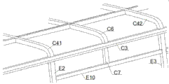
Fig. 2 is the perspective view of top cover assembly in Fig. 1.
Fig. 3 is the perspective view that in Fig. 2, the upper bent cross beams of the first perforation and second connects upper bent cross beams.
Fig. 4 is the enlarged diagram at X place in Fig. 1.
Fig. 5 is the front view of front wall assembly in Fig. 4.
Fig. 6 is the left view of Fig. 5.
Fig. 7 is the enlarged diagram at Y place in Fig. 1.
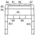
Fig. 8 is the front view of back wall assembly in Fig. 7.
Fig. 9 is the right elevation of Fig. 8.
Figure 10 is the enlarged diagram at Z place in Fig. 1.
Figure 11 is the front view of side wall assembly in Figure 10.
Figure 12 is the birds-eye view of chassis assembly in Fig. 1.
Figure 13 is the perspective view of support post assembly in Fig. 1.
Figure 14 is the cross sectional representation at place, Qianmen in Fig. 1.
Figure 15 is the cross sectional representation at middle door place in Fig. 1.
In figure:
Front wall assembly A: front wall head piece A1, Front Windshield entablatrance A2, front windshield lower beam A3, left and right front wall pillar A4, Front Windshield connect column A5, Front Windshield connecting panel A6, Front Windshield tie-beam A7;
Back wall assembly B: air regulator column B7, middle door connection column B8, rear door crossbeam B9, left and right rear door column B10, middle door tie-beam B11 behind back wall head piece B1, rear air window upper crossbeam B2, rear air regulator cross sill B3, left and right back wall pillar B4, rear air regulator tie-beam B5, rear air regulator connection column B6, left and right;
Top cover assembly C: front upper bent cross beams C1, rear upper bent cross beams C2, side-window upper beam C3, bent cross beams C4 in perforation, first connects upper bent cross beams C41, second connects upper bent cross beams C42, the 3rd connects upper bent cross beams C43, the 4th connects upper bent cross beams C44, the 5th connects upper bent cross beams C45, the 6th connects upper bent cross beams C46, the 7th connects upper bent cross beams C47, the 8th connects upper bent cross beams C48, the 9th connects upper bent cross beams C49, segmentation beam C5, non-penetrating upper bent cross beams C6, upper curved heel post C7, top cover leads directly to crossbeam C8, the first top cover leads directly to crossbeam C81, the second top cover leads directly to crossbeam C82, the 3rd top cover leads directly to crossbeam C83, the 4th top cover leads directly to crossbeam C84, the 5th top cover leads directly to crossbeam C85, the 6th top cover leads directly to crossbeam C86, the 7th top cover leads directly to crossbeam C87, top cover right cylinder C9, vertical diagonal ligament beam C10, horizontal diagonal ligament beam C11, horizontal horizontal support beam C12, sub-longeron C13,
Chassis assembly D: anterior connect crossbeam D1, Qianmen body transom D2, body transom D3, No. two body transom D4, in front of the door body transom D5, in body transom D6, No. three body transom D7, No. four body transom D8, rear portions connect crossbeam D9, non-penetrating underframe longeron D10, front-wheel bag step crossbeam D11, vertical undercarriage bea D12 behind the door;
Side wall assembly E: front window column E1, front side wall outer panel E2, a side window pillar E3, No. two side window pillar E4, in column E5 in front of the door, in column E6 behind the door, No. three side window pillar E7, No. four side window pillar E8, rear side window pillar E9, tie-beam E10 on side-window, side-window underbeam E11, skirt encloses column E12, bottom skirt beam E13, lower gusset diagonal ligament beam E14, upper gusset diagonal ligament beam E15, waist rail E16, the E17 of front wheel housing place, the E18 of rear wheel cover place, front deep beam E19, rear deep beam E20, post beam E21,
Support post assembly F: framework beam F1, vertically framework beam F2, first vertical framework beam F21, second vertical framework beam F22, the 3rd vertical framework beam F23, the 4th vertical framework beam F24, the 5th vertical framework beam F25, the vertical framework beam F26 of the six roots of sensation, the 7th vertical framework beam F27, the 8th vertical framework beam F28, the 9th vertical framework beam F29, the tenth vertical framework beam F20, Vierendeel girder F3 anyhow; Front combination crossbeam G, rear combination crossbeam H, front combination column I, rear combination column J.
The specific embodiment
Below in conjunction with accompanying drawing explanation and the specific embodiment, the present invention is further detailed explanation.
Referring to figure 1 – Figure 15, a kind of all-bearing car body structure of new-energy urban bus, comprise front wall assembly A, back wall assembly B, top cover assembly C, chassis assembly D and two side wall assembly E, the two ends of described top cover assembly C are connected with the upper end of front wall assembly A, back wall assembly B respectively, the lower end of front wall assembly A, back wall assembly B is connected with the two ends of chassis assembly D respectively, and chassis assembly D is connected with top cover assembly C by side wall assembly E;
Described Self-supporting body structure also comprises support post assembly F, and the two ends up and down of this support post assembly F are connected with top cover assembly C, chassis assembly D respectively.
Described support post assembly F comprises the F1 of framework beam anyhow connected vertically and vertical framework beam F2, and the two ends up and down of described vertical framework beam F2 are connected with top cover assembly C, chassis assembly D respectively.
Described vertical framework beam F2 is that welding or bolt are connected with the connection mode between top cover assembly C, chassis assembly D.
Described vertical framework beam F2 and connection mode between top cover assembly C, chassis assembly D are bolt while being connected, and vertically the two ends up and down of framework beam F2 are welded with in order to bolted rebound or L-type plate.
The manufacture raw material of described vertical support beam F2 is round steel pipe, Rouno Cormer Pregrinding Wheel square steel or aluminium alloy extrusions.
The upper position between first vertical framework beam F21, the 8th vertical framework beam F28 of described top cover assembly C is provided with the double-layer frame cavity body structure of shelving energy storage device, and this double-layer frame cavity body structure comprises the straight-through crossbeam C81 of the first top cover being parallel to each other, the straight-through crossbeam C83 of the 3rd top cover, the straight-through crossbeam C85 of the 5th top cover, the straight-through crossbeam C87 of the 7th top cover and first connecting upper bent cross beams C41, second and connect upper bent cross beams C42, the 3rd and connect upper bent cross beams C43, the 4th and connect upper bent cross beams C44 corresponding thereto.
Described first connects upper bent cross beams C41, second connects upper bent cross beams C42, the 3rd connects upper bent cross beams C43, the 4th connects upper bent cross beams C44 all passes through top cover right cylinder C9, vertical diagonal ligament beam C10 leads directly to crossbeam C81 with the first corresponding top cover, the 3rd top cover leads directly to crossbeam C83, the 5th top cover leads directly to crossbeam C85, the straight-through crossbeam C87 of the 7th top cover is connected, the opposite side of connection and first vertical framework beam F21, second vertical framework beam F22, the 3rd vertical framework beam F23, the 4th vertical framework beam F24, the 5th vertical framework beam F25, the vertical framework beam F26 of the six roots of sensation, the 7th vertical framework beam F27, the upper end of the 8th vertical framework beam F28 connects one to one, the every corresponding two vertical framework beam F2 of the straight-through crossbeam C8 of top cover.
The lower end of described first vertical framework beam F21, second vertical framework beam F22 is connected with the Qianmen body transom D2 in chassis assembly D by front-wheel bag step crossbeam D11, vertical undercarriage bea D12 successively.
The manufactured materials of described chassis assembly D is rectangular steel pipe.
The front window column E1 that described side wall assembly E comprises, front side wall outer panel E2, side window pillar E3, No. two side window pillar E4, in front of the door column E5, in column E6, No. three side window pillar E7, No. four side window pillar E8, rear side window pillar E9 are that integral type connects column behind the door.
Principle of the present invention is described as follows:
Referring to Fig. 1, a kind of all-bearing car body structure of new-energy urban bus, comprise front wall assembly A, back wall assembly B, top cover assembly C, chassis assembly D, support post assembly F and two side wall assembly E, the two ends of described top cover assembly C are connected with the upper end of front wall assembly A, back wall assembly B respectively, the lower end of front wall assembly A, back wall assembly B is connected with the two ends of chassis assembly D respectively, chassis assembly D is connected with top cover assembly C by side wall assembly E, and the two ends up and down of support post assembly F are connected with top cover assembly C, chassis assembly D respectively.
Referring to Fig. 2 and Fig. 3, top cover assembly C: being upper and lower two-layer frame cavity body structure, is to seal completely stressed ring structure.Wherein, superstructure comprises bent cross beams C4, segmentation beam C5 in front upper bent cross beams C1, rear upper bent cross beams C2, side-window upper beam C3, nine perforations, three couples of non-penetrating upper bent cross beams C6, the non-penetrating upper bent cross beams C6 setting of aliging with upper curved heel post C7 through side-window upper beam C3, understructure comprises that seven top covers lead directly to crossbeam C8, and wherein, the first top cover leads directly to crossbeam C81, the 3rd top cover leads directly to crossbeam C83, the 5th top cover leads directly to crossbeam C85, the straight-through crossbeam C87 of the 7th top cover passes through top cover right cylinder C9, vertical diagonal ligament beam C10 connects one by one with bent cross beams C4 in corresponding four perforations, and the second top cover leads directly to crossbeam C82, the 4th top cover leads directly to crossbeam C84, the straight-through crossbeam C86 of the 6th top cover connects with the corresponding non-penetrating upper bent cross beams C6 of three couples one by one by vertical diagonal ligament beam C10, between the straight-through crossbeam C8 of adjacent top cover, passes through horizontal diagonal ligament beam C11, horizontal horizontal support beam C12, the framework that sub-longeron C13 is connected to form meter font is in order to shelve energy storage device, as electrokinetic cell or compression natural gas tank etc., realized the overhead of energy storage device, thereby optimized bus passenger space, simultaneously, the additional load increasing for ease of burden energy storage device, at the straight-through crossbeam C81 of the first top cover, the 3rd top cover leads directly to crossbeam C83, the 5th top cover leads directly to crossbeam C85, the 7th top cover leads directly to crossbeam C87 above and top cover right cylinder C9, the opposite side at the position that vertical diagonal ligament beam C10 all connects respectively with first vertical framework beam F21, second vertical framework beam F22, the 3rd vertical framework beam F23, the 4th vertical framework beam F24, the 5th vertical framework beam F25, the vertical framework beam F26 of the six roots of sensation, the 7th vertical framework beam F27, the upper end of the 8th vertical framework beam F28 connects one to one, and the every corresponding two vertical framework beam F2 of the straight-through crossbeam C8 of top cover, make top cover lead directly to crossbeam C8, vertical framework beam F2, between body transom, form a new stressed ring of sealing.
Referring to figure 4 – Fig. 6, front wall assembly A: front wall assembly A is from sealing completely stressed ring structure as.Front wall head piece A1 and front upper bent cross beams C1 are welded into front combination crossbeam G, front upper bent cross beams C1, first connects segmentation beam C5 between bent cross beams C4 and is connected the column A5 setting of aliging with Front Windshield, after left and right front wall pillar A4 is welded into front combination column I with front window column E1 with corresponding being fixedly connected with of front portion perforation crossbeam D1.
Referring to figure 7 – Fig. 9, back wall assembly B: back wall assembly B is from sealing completely stressed ring structure as.Back wall head piece B1 and rear upper bent cross beams C2 are welded into rear combination crossbeam H, after left and right back wall pillar B4 is welded into rear combination column J with rear side window pillar E9, connect corresponding being fixedly connected with of crossbeam D9 with rear portion.
Referring to Figure 10, Figure 11, side wall assembly E: side wall assembly E is from sealing completely stressed ring structure as.In side wall assembly E, adopt through side window pillar, on side-window, tie-beam E10, side-window underbeam E11 are fixed between side window pillar, are conducive to form the stressed ring structure of whole transverse seal.Before and after left and right sides is trapped among, wheel cover place is provided with that horizontal connection side window pillar and skirt enclose the front deep beam E19 of column E12, rear deep beam E20 and post beam E21 forms load-carrying unit, this load-carrying unit and underframe corresponding being connected and fixed of rear wheel cover place skeleton of going forward, makes side wall assembly form integral rigidity framework.
Referring to Figure 12, chassis assembly D: chassis assembly D is from sealing completely stressed ring structure as one.Chassis assembly D is all comprised of rectangular steel pipe, and the chassis assembly consisting of rectangular steel pipe is integral rigidity bearing frame, is not easy to produce diamonding, and distribution of force is even, and structural stability is strong.
Referring to Figure 13, support post assembly F: comprise Vierendeel girder F3, the mutual F1 of framework beam anyhow connected vertically and vertical framework beam F2, wherein, ten vertical framework beam F2 are fixedly supported between the straight-through crossbeam C8 of top cover and body transom, corresponding with the stressed ring position of totally-enclosed cross-sectional structure, form the three-dimensional Self-supporting body structure of strengthening.
Referring to Fig. 1, Fig. 2, Figure 11, Figure 12 and Figure 13 are known: top cover assembly C, side wall assembly E, corresponding annexation between chassis assembly D and support post assembly F is: non-penetrating upper bent cross beams C6 is successively through side-window upper beam C3, after upper curved heel post C7, be connected with tie-beam E10 on side-window, first, two, three, four, six, eight, nine connect bent cross beams C4 respectively after side-window upper beam C3 with front side wall outer panel E2, a side window pillar E3, No. two side window pillar E4, in column E5 in front of the door, in column E6 behind the door, No. three side window pillar E7, the upper end of No. four side window pillar E8 connects one to one, front window column E1, front side wall outer panel E2, a side window pillar E3, No. two side window pillar E4, in column E5 in front of the door, in column E6 behind the door, No. three side window pillar E7, No. four side window pillar E8, the lower end of rear side window pillar E9 connects crossbeam D1 with front portion respectively, Qianmen body transom D2, a body transom D3, No. two body transom D4, in body transom D5 in front of the door, in body transom D6 behind the door, No. three body transom D7, No. four body transom D8, rear portion connects crossbeam D9 and connects one to one,
First, three, five, seven top covers lead directly to crossbeam C8 above and top cover right cylinder C9, the opposite side at the position that vertical diagonal ligament beam C10 all connects is respectively with first, two, three, four, five, six, seven, the upper end of eight vertical framework beam F2 connects one to one, the every corresponding two vertical framework beam F2 of the straight-through crossbeam C8 of top cover, first, two, three, four, five, six, seven, eight, nine, the lower end of ten vertical framework beam F2 successively with Qianmen body transom D2, a body transom D3, No. two body transom D4, in body transom D5 in front of the door, in behind the door body transom D6 be connected, the every corresponding two vertical framework beam F2 of body transom.
Referring to Figure 14, the cross sectional representation at place, Qianmen: the cross-sectional plane at place, Qianmen is from sealing completely stressed ring structure as.By bent cross beams C41, side-window upper beam C3, front side wall outer panel E2, Qianmen body transom D2 in the first perforation, form external overall and seal stressed ring structure; By the upside of the straight-through crossbeam C81 of the first top cover, connect upper bent cross beams C41 with top cover right cylinder C9, vertical diagonal ligament beam C10, first and form the three-dimensional reinforced frame of upper interior, by the downside of the straight-through crossbeam C81 of the first top cover with vertically framework beam F2, front-wheel bag step crossbeam D11, vertical undercarriage bea D12, Qianmen body transom D2 form lower inner part solid reinforced frame; All skeletons form inside and outside portion integrated-reinforcing framework, improve car load anti-torsion, counter-bending ability.
Referring to Figure 15, the cross sectional representation at middle door place: the cross-sectional plane at middle door place is from sealing completely stressed ring structure as.By the 4th connect bent cross beams C44, side-window upper beam C3, in front of the door column E5, in front of the door body transom D5 form external overall and seal stressed ring structure; By the upside of the straight-through crossbeam C87 of the 7th top cover, connect upper bent cross beams C44 with top cover right cylinder C9, vertical diagonal ligament beam C10, the 4th and form the three-dimensional reinforced frame of upper interior, by the downside of the straight-through crossbeam C87 of the 7th top cover and with vertical framework beam F2, in front of the door body transom D5 form lower inner part solid reinforced frame; All skeletons form inside and outside portion integrated-reinforcing framework, improve the flexion torsion structural strength of car load.
Embodiment:
A kind of all-bearing car body structure of new-energy urban bus, comprise front wall assembly A, back wall assembly B, top cover assembly C, chassis assembly D, two side wall assembly E and support post assembly F, the two ends of described top cover assembly C are connected with the upper end of front wall assembly A, back wall assembly B respectively, the lower end of front wall assembly A, back wall assembly B is connected with the two ends of chassis assembly D respectively, chassis assembly D is connected with top cover assembly C by side wall assembly E, and the two ends up and down of support post assembly F are connected with top cover assembly C, chassis assembly D respectively;
Described top cover assembly C comprises: the front upper bent cross beams C1 being parallel to each other, rear upper bent cross beams C2 and between two side-window upper beam C3 arranging, on described side-window upper beam C3, be positioned at front upper bent cross beams C1, position between rear upper bent cross beams C2 is connected with bent cross beams C4 in nine perforations that parallel with front upper bent cross beams C1 in turn, be followed successively by bent cross beams C41 in the first perforation, second connects upper bent cross beams C42, the 3rd connects upper bent cross beams C43, the 4th connects upper bent cross beams C44, the 5th connects upper bent cross beams C45, the 6th connects upper bent cross beams C46, the 7th connects upper bent cross beams C47, the 8th connects upper bent cross beams C48 and the 9th connects upper bent cross beams C49, in adjacent perforation between bent cross beams C4 and connect bent cross beams C4 and front upper bent cross beams C1, between rear upper bent cross beams C2, be all provided with segmentation beam C5, be positioned at bent cross beams C41 in the first perforation, on the 4th segmentation beam C5 connecting between upper bent cross beams C44, be all provided with the non-penetrating upper bent cross beams C6 that a pair of and front upper bent cross beams C1 parallels, one end of this non-penetrating upper bent cross beams C6 is connected with segmentation beam C5, the other end is connected with side-window upper beam C3, the opposite side of side-window upper beam C3 is provided with the upper curved heel post C7 mutually concordant with non-penetrating upper bent cross beams C6,
Described first connect bent cross beams C41 to the four connect upper bent cross beams C44 in totally four perforations each correspondence of below of bent cross beams C4 and non-penetrating upper bent cross beams C6 be provided with a top cover paralleling with front upper bent cross beams C1 and lead directly to crossbeam C8, the quantity of the straight-through crossbeam C8 of described top cover is seven, wherein, the first top cover leads directly to crossbeam C81, the 3rd top cover leads directly to crossbeam C83, the 5th top cover leads directly to crossbeam C85, the straight-through crossbeam C87 of the 7th top cover passes through top cover right cylinder C9, vertical diagonal ligament beam C10 connects one by one with bent cross beams C4 in corresponding four perforations, described the second top cover leads directly to crossbeam C82, the 4th top cover leads directly to crossbeam C84, the straight-through crossbeam C86 of the 6th top cover connects with the corresponding non-penetrating upper bent cross beams C6 of three couples one by one by vertical diagonal ligament beam C10, between the straight-through crossbeam C8 of adjacent top cover, pass through horizontal diagonal ligament beam C11, horizontal horizontal support beam C12, sub-longeron C13 is connected,
Described front wall assembly A comprises: front wall head piece A1, Front Windshield entablatrance A2, front windshield lower beam A3 and left and right front wall pillar A4, the bottom of described left and right front wall pillar A4 is connected with front windshield lower beam A3, upper end and front wall head piece A1, the two ends of Front Windshield entablatrance A2 are connected, the middle part of front wall head piece A1 is connected with a side at Front Windshield entablatrance A2 middle part by the Front Windshield connection column A5 of a plurality of arcs, the opposite side at Front Windshield entablatrance A2 middle part is connected with the middle part of Front Windshield tie-beam A7 by Front Windshield connecting panel A6, the two ends of Front Windshield tie-beam A7 are connected with left and right front wall pillar A4, Front Windshield tie-beam A7, Front Windshield entablatrance A2, between front windshield lower beam A3, be parallel to each other between two, and Front Windshield tie-beam A7 is positioned at Front Windshield entablatrance A2, between front windshield lower beam A3, described left and right front wall pillar A4 is that integral type connects column,
Described back wall assembly B comprises: back wall head piece B1, rear air window upper crossbeam B2, rear air regulator cross sill B3 and left and right back wall pillar B4, the two ends of the two ends of described back wall head piece B1 and rear air regulator tie-beam B5, the upper end of left and right back wall pillar B4 is connected, the middle part of back wall head piece B1 is connected with the middle part of rear air window upper crossbeam B2 by the rear air regulator connection column B6 of arc, the two ends of rear air window upper crossbeam B2 are connected with the middle part of air regulator column B7 behind left and right, left and right after air regulator column B7 two ends respectively with back wall head piece B1, a side of rear air regulator cross sill B3 is connected, the two ends of rear air regulator cross sill B3 are connected with left and right back wall pillar B4, the opposite side of rear air regulator cross sill B3 is connected with the middle part of rear door crossbeam B9 by a plurality of middle door connection column B8, the two ends of rear door crossbeam B9 are connected with a side of left and right rear door column B10, the opposite side of left and right rear door column B10 is connected with left and right back wall pillar B4 by middle door tie-beam B11, described left and right back wall pillar B4 is that integral type connects column,
Described side wall assembly E comprises: the front window column E1 being parallel to each other, front side wall outer panel E2, in front of the door column E5, in column E6 and rear side window pillar E9 behind the door, described front side wall outer panel E2, in between column E5, be provided with in front of the door a side window pillar E3 who parallels with front window column E1, No. two side window pillar E4, in between column E6 and rear side window pillar E9, be provided with No. three side window pillar E7 that parallel with front window column E1 behind the door, No. four side window pillar E8, front side wall outer panel E2 extremely rear side window pillar E9 is connected by tie-beam E10 on side-window eight root posts upper end between any two totally, middle part is all connected by side-window underbeam E11, on side-window underbeam E11, be positioned at No. one side window pillar E3, in behind the door the position between column E6 by many skirts, enclose column E12 and be connected with bottom skirt beam E13, bottom skirt beam E13 is connected with a side of waist rail E16 by lower gusset diagonal ligament beam E14, the opposite side of waist rail E16 is connected with side-window underbeam E11 by upper gusset diagonal ligament beam E15, on side-window underbeam E11, be positioned at Qianmen column E2, position between a side window pillar E3 is connected with the E17 of front wheel housing place, on side-window underbeam E11, be arranged in column E6 behind the door, position between No. three side window pillar E7 is connected with the E18 of rear wheel cover place, the E17 of front wheel housing place, the top of the E18 of rear wheel cover place respectively with front deep beam E19, a side of rear deep beam E20 is connected, front deep beam E19, the opposite side of rear deep beam E20 is all connected with side-window underbeam E11 by post beam E21, column E12 is enclosed with skirt respectively in the two ends of front deep beam E19, No. one side window pillar E3 is connected, column E12 is enclosed with skirt respectively in the two ends of rear deep beam E20, No. three side window pillar E7 is connected, described front window column E1, front side wall outer panel E2, side window pillar E3, No. two side window pillar E4, in front of the door column E5, in column E6, No. three side window pillar E7, No. four side window pillar E8, rear side window pillar E9 are that integral type connects column behind the door,
Described chassis assembly D comprises: the front portion that is parallel to each other connect crossbeam D1, Qianmen body transom D2, in front of the door body transom D5, in body transom D6 and rear portion perforation crossbeam D9 behind the door, described Qianmen body transom D2, in between body transom D5, be disposed with in front of the door a body transom D3 who parallels with Qianmen body transom D2, No. two body transom D4, in body transom D6 and rear portion connect between crossbeam D9 and are disposed with No. three body transom D7 that parallel with Qianmen body transom D2 behind the door, No. four body transom D8, and the anterior crossbeam D1 that connects, Qianmen body transom D2, a body transom D3, No. two body transom D4, in body transom D5 in front of the door, in body transom D6 behind the door, No. three body transom D7, No. four body transom D8, rear portion connects between crossbeam D9 and all by non-penetrating underframe longeron D10, is connected, the manufactured materials of described chassis assembly D is rectangular steel pipe,
Described support post assembly F comprises: the F1 of framework beam anyhow connected vertically and vertical framework beam F2; The quantity of described vertical framework beam F2 is ten, wherein, on first vertical framework beam F21, second vertical framework beam F22, the 8th vertical framework beam F28, the 9th vertical framework beam F29, the tenth vertical framework beam F20, be all connected with respectively a Vierendeel girder F3;
Corresponding annexation between described front wall assembly A, back wall assembly B, top cover assembly C, chassis assembly D, side wall assembly E, support post assembly F is:
Described front upper bent cross beams C1 and front wall head piece A1 are welded into front combination crossbeam G, and front upper bent cross beams C1, first connects segmentation beam C5 between bent cross beams C4 and is connected the column A5 setting of aliging with Front Windshield, and rear upper bent cross beams C2 and back wall head piece B1 are welded into rear combination crossbeam H, described first connect bent cross beams C41, second connect upper bent cross beams C42, the 3rd connect upper bent cross beams C43, the 4th connect upper bent cross beams C44, the 6th connect upper bent cross beams C46, the 8th connect upper bent cross beams C48, the 9th connect upper bent cross beams C49 respectively after side-window upper beam C3 with front side wall outer panel E2, side window pillar E3, No. two side window pillar E4, in front of the door column E5, in behind the door the upper end of column E6, No. three side window pillar E7, No. four side window pillar E8 connect one to one, the rear and front end of described side-window upper beam C3 is fixedly connected with the upper end of left and right front wall pillar A4, left and right back wall pillar B4 respectively, and the opposite side of side-window upper beam C3 is connected with tie-beam E10 on side-window by upper curved heel post C7, described the first top cover leads directly to crossbeam C81, the 3rd top cover leads directly to crossbeam C83, the 5th top cover leads directly to crossbeam C85, the 7th top cover leads directly to crossbeam C87 above and top cover right cylinder C9, the opposite side at the position that vertical diagonal ligament beam C10 all connects respectively with first vertical framework beam F21, second vertical framework beam F22, the 3rd vertical framework beam F23, the 4th vertical framework beam F24, the 5th vertical framework beam F25, the vertical framework beam F26 of the six roots of sensation, the 7th vertical framework beam F27, the upper end of the 8th vertical framework beam F28 connects one to one, the every corresponding two vertical framework beam F2 of the straight-through crossbeam C8 of top cover,
After described left and right front wall pillar A4 is welded into front combination column I with front window column E1, connect corresponding being fixedly connected with of crossbeam D1 with front portion, after described left and right back wall pillar B4 is welded into rear combination column J with rear side window pillar E9, connect corresponding being fixedly connected with of crossbeam D9 with rear portion;
Described front window column E1, front side wall outer panel E2, a side window pillar E3, No. two side window pillar E4, in column E5 in front of the door, in column E6 behind the door, No. three side window pillar E7, No. four side window pillar E8, the lower end of rear side window pillar E9 connects crossbeam D1 with front portion respectively, Qianmen body transom D2, a body transom D3, No. two body transom D4, in body transom D5 in front of the door, in body transom D6 behind the door, No. three body transom D7, No. four body transom D8, rear portion connects crossbeam D9 and connects one to one,
The lower end of described first vertical framework beam F21, second vertical framework beam F22, the 3rd vertical framework beam F23, the 4th vertical framework beam F24, the 5th vertical framework beam F25, the vertical framework beam F26 of the six roots of sensation, the 7th vertical framework beam F27, the 8th vertical framework beam F28, the 9th vertical framework beam F29, the tenth vertical framework beam F20 successively with Qianmen body transom D2, body transom D3, No. two body transom D4, in front of the door body transom D5, in behind the door body transom D6 be connected, the every corresponding two vertical framework beam F2 of body transom; The lower end of described first vertical framework beam F21, second vertical framework beam F22 is connected with Qianmen body transom D2 by front-wheel bag step crossbeam D11, vertical undercarriage bea D12 successively.
Therefore, front wall assembly in bus body structure, back wall assembly, left/right side wall assembly, top cover assembly, chassis assembly and support post assembly burst are made after the stressed ring of sealing, by side-window upper beam, be connected and fixed again, one of the fixing formation of combination has multi-level successively, the general frame of three-dimensional heavier-duty enclosed ring, there is carload effectively transmission and decomposition effect, when have External Force Acting at vehicle body certain position time, load can decompose rapidly by the enclosed ring of full carrying each position of vehicle body, bearing capacity is successively weakened, reach the whole stressed uniform technical purpose of vehicle body, anti-inclination, anti-overload capacity is strong.Therefore the present invention can not only optimize bus passenger space, improve the homogeneity of body structure integrated carrying, and the transmission effect of local structure is strong, have the stressed ring design of sealing on support post assembly.