EP1043067A2 - A ceramic support capable of supporting a catalyst, a catalyst-ceramic body and processes for producing same - Google Patents
A ceramic support capable of supporting a catalyst, a catalyst-ceramic body and processes for producing same Download PDFInfo
- Publication number
- EP1043067A2 EP1043067A2 EP00107123A EP00107123A EP1043067A2 EP 1043067 A2 EP1043067 A2 EP 1043067A2 EP 00107123 A EP00107123 A EP 00107123A EP 00107123 A EP00107123 A EP 00107123A EP 1043067 A2 EP1043067 A2 EP 1043067A2
- Authority
- EP
- European Patent Office
- Prior art keywords
- cordierite
- ceramic support
- catalyst
- ceramic
- honeycomb structure
- Prior art date
- Legal status (The legal status is an assumption and is not a legal conclusion. Google has not performed a legal analysis and makes no representation as to the accuracy of the status listed.)
- Withdrawn
Links
Images

Classifications
-
- B—PERFORMING OPERATIONS; TRANSPORTING
- B01—PHYSICAL OR CHEMICAL PROCESSES OR APPARATUS IN GENERAL
- B01D—SEPARATION
- B01D63/00—Apparatus in general for separation processes using semi-permeable membranes
- B01D63/06—Tubular membrane modules
- B01D63/066—Tubular membrane modules with a porous block having membrane coated passages
-
- B—PERFORMING OPERATIONS; TRANSPORTING
- B01—PHYSICAL OR CHEMICAL PROCESSES OR APPARATUS IN GENERAL
- B01D—SEPARATION
- B01D53/00—Separation of gases or vapours; Recovering vapours of volatile solvents from gases; Chemical or biological purification of waste gases, e.g. engine exhaust gases, smoke, fumes, flue gases, aerosols
- B01D53/34—Chemical or biological purification of waste gases
- B01D53/92—Chemical or biological purification of waste gases of engine exhaust gases
- B01D53/94—Chemical or biological purification of waste gases of engine exhaust gases by catalytic processes
- B01D53/944—Simultaneously removing carbon monoxide, hydrocarbons or carbon making use of oxidation catalysts
-
- B—PERFORMING OPERATIONS; TRANSPORTING
- B01—PHYSICAL OR CHEMICAL PROCESSES OR APPARATUS IN GENERAL
- B01D—SEPARATION
- B01D67/00—Processes specially adapted for manufacturing semi-permeable membranes for separation processes or apparatus
- B01D67/0039—Inorganic membrane manufacture
- B01D67/0041—Inorganic membrane manufacture by agglomeration of particles in the dry state
- B01D67/00414—Inorganic membrane manufacture by agglomeration of particles in the dry state by plasma spraying
-
- B—PERFORMING OPERATIONS; TRANSPORTING
- B01—PHYSICAL OR CHEMICAL PROCESSES OR APPARATUS IN GENERAL
- B01D—SEPARATION
- B01D71/00—Semi-permeable membranes for separation processes or apparatus characterised by the material; Manufacturing processes specially adapted therefor
- B01D71/02—Inorganic material
- B01D71/024—Oxides
-
- B—PERFORMING OPERATIONS; TRANSPORTING
- B01—PHYSICAL OR CHEMICAL PROCESSES OR APPARATUS IN GENERAL
- B01D—SEPARATION
- B01D71/00—Semi-permeable membranes for separation processes or apparatus characterised by the material; Manufacturing processes specially adapted therefor
- B01D71/02—Inorganic material
- B01D71/024—Oxides
- B01D71/025—Aluminium oxide
-
- B—PERFORMING OPERATIONS; TRANSPORTING
- B01—PHYSICAL OR CHEMICAL PROCESSES OR APPARATUS IN GENERAL
- B01J—CHEMICAL OR PHYSICAL PROCESSES, e.g. CATALYSIS OR COLLOID CHEMISTRY; THEIR RELEVANT APPARATUS
- B01J21/00—Catalysts comprising the elements, oxides, or hydroxides of magnesium, boron, aluminium, carbon, silicon, titanium, zirconium, or hafnium
- B01J21/14—Silica and magnesia
-
- B—PERFORMING OPERATIONS; TRANSPORTING
- B01—PHYSICAL OR CHEMICAL PROCESSES OR APPARATUS IN GENERAL
- B01J—CHEMICAL OR PHYSICAL PROCESSES, e.g. CATALYSIS OR COLLOID CHEMISTRY; THEIR RELEVANT APPARATUS
- B01J23/00—Catalysts comprising metals or metal oxides or hydroxides, not provided for in group B01J21/00
- B01J23/38—Catalysts comprising metals or metal oxides or hydroxides, not provided for in group B01J21/00 of noble metals
- B01J23/40—Catalysts comprising metals or metal oxides or hydroxides, not provided for in group B01J21/00 of noble metals of the platinum group metals
- B01J23/42—Platinum
-
- B—PERFORMING OPERATIONS; TRANSPORTING
- B01—PHYSICAL OR CHEMICAL PROCESSES OR APPARATUS IN GENERAL
- B01J—CHEMICAL OR PHYSICAL PROCESSES, e.g. CATALYSIS OR COLLOID CHEMISTRY; THEIR RELEVANT APPARATUS
- B01J23/00—Catalysts comprising metals or metal oxides or hydroxides, not provided for in group B01J21/00
- B01J23/38—Catalysts comprising metals or metal oxides or hydroxides, not provided for in group B01J21/00 of noble metals
- B01J23/40—Catalysts comprising metals or metal oxides or hydroxides, not provided for in group B01J21/00 of noble metals of the platinum group metals
- B01J23/46—Ruthenium, rhodium, osmium or iridium
- B01J23/464—Rhodium
-
- B—PERFORMING OPERATIONS; TRANSPORTING
- B01—PHYSICAL OR CHEMICAL PROCESSES OR APPARATUS IN GENERAL
- B01J—CHEMICAL OR PHYSICAL PROCESSES, e.g. CATALYSIS OR COLLOID CHEMISTRY; THEIR RELEVANT APPARATUS
- B01J23/00—Catalysts comprising metals or metal oxides or hydroxides, not provided for in group B01J21/00
- B01J23/38—Catalysts comprising metals or metal oxides or hydroxides, not provided for in group B01J21/00 of noble metals
- B01J23/54—Catalysts comprising metals or metal oxides or hydroxides, not provided for in group B01J21/00 of noble metals combined with metals, oxides or hydroxides provided for in groups B01J23/02 - B01J23/36
- B01J23/56—Platinum group metals
- B01J23/63—Platinum group metals with rare earths or actinides
-
- B—PERFORMING OPERATIONS; TRANSPORTING
- B01—PHYSICAL OR CHEMICAL PROCESSES OR APPARATUS IN GENERAL
- B01J—CHEMICAL OR PHYSICAL PROCESSES, e.g. CATALYSIS OR COLLOID CHEMISTRY; THEIR RELEVANT APPARATUS
- B01J35/00—Catalysts, in general, characterised by their form or physical properties
- B01J35/50—Catalysts, in general, characterised by their form or physical properties characterised by their shape or configuration
- B01J35/56—Foraminous structures having flow-through passages or channels, e.g. grids or three-dimensional [3D] monoliths
- B01J35/57—Honeycombs
-
- B—PERFORMING OPERATIONS; TRANSPORTING
- B01—PHYSICAL OR CHEMICAL PROCESSES OR APPARATUS IN GENERAL
- B01J—CHEMICAL OR PHYSICAL PROCESSES, e.g. CATALYSIS OR COLLOID CHEMISTRY; THEIR RELEVANT APPARATUS
- B01J37/00—Processes, in general, for preparing catalysts; Processes, in general, for activation of catalysts
- B01J37/0009—Use of binding agents; Moulding; Pressing; Powdering; Granulating; Addition of materials ameliorating the mechanical properties of the product catalyst
-
- C—CHEMISTRY; METALLURGY
- C04—CEMENTS; CONCRETE; ARTIFICIAL STONE; CERAMICS; REFRACTORIES
- C04B—LIME, MAGNESIA; SLAG; CEMENTS; COMPOSITIONS THEREOF, e.g. MORTARS, CONCRETE OR LIKE BUILDING MATERIALS; ARTIFICIAL STONE; CERAMICS; REFRACTORIES; TREATMENT OF NATURAL STONE
- C04B35/00—Shaped ceramic products characterised by their composition; Ceramics compositions; Processing powders of inorganic compounds preparatory to the manufacturing of ceramic products
- C04B35/01—Shaped ceramic products characterised by their composition; Ceramics compositions; Processing powders of inorganic compounds preparatory to the manufacturing of ceramic products based on oxide ceramics
- C04B35/16—Shaped ceramic products characterised by their composition; Ceramics compositions; Processing powders of inorganic compounds preparatory to the manufacturing of ceramic products based on oxide ceramics based on silicates other than clay
- C04B35/18—Shaped ceramic products characterised by their composition; Ceramics compositions; Processing powders of inorganic compounds preparatory to the manufacturing of ceramic products based on oxide ceramics based on silicates other than clay rich in aluminium oxide
- C04B35/195—Alkaline earth aluminosilicates, e.g. cordierite or anorthite
-
- C—CHEMISTRY; METALLURGY
- C04—CEMENTS; CONCRETE; ARTIFICIAL STONE; CERAMICS; REFRACTORIES
- C04B—LIME, MAGNESIA; SLAG; CEMENTS; COMPOSITIONS THEREOF, e.g. MORTARS, CONCRETE OR LIKE BUILDING MATERIALS; ARTIFICIAL STONE; CERAMICS; REFRACTORIES; TREATMENT OF NATURAL STONE
- C04B38/00—Porous mortars, concrete, artificial stone or ceramic ware; Preparation thereof
-
- B—PERFORMING OPERATIONS; TRANSPORTING
- B01—PHYSICAL OR CHEMICAL PROCESSES OR APPARATUS IN GENERAL
- B01D—SEPARATION
- B01D2255/00—Catalysts
- B01D2255/10—Noble metals or compounds thereof
- B01D2255/102—Platinum group metals
- B01D2255/1021—Platinum
-
- B—PERFORMING OPERATIONS; TRANSPORTING
- B01—PHYSICAL OR CHEMICAL PROCESSES OR APPARATUS IN GENERAL
- B01D—SEPARATION
- B01D2255/00—Catalysts
- B01D2255/10—Noble metals or compounds thereof
- B01D2255/102—Platinum group metals
- B01D2255/1025—Rhodium
-
- B—PERFORMING OPERATIONS; TRANSPORTING
- B01—PHYSICAL OR CHEMICAL PROCESSES OR APPARATUS IN GENERAL
- B01D—SEPARATION
- B01D2323/00—Details relating to membrane preparation
- B01D2323/219—Specific solvent system
- B01D2323/225—Use of supercritical fluids
-
- B—PERFORMING OPERATIONS; TRANSPORTING
- B01—PHYSICAL OR CHEMICAL PROCESSES OR APPARATUS IN GENERAL
- B01D—SEPARATION
- B01D2325/00—Details relating to properties of membranes
- B01D2325/10—Catalysts being present on the surface of the membrane or in the pores
-
- B—PERFORMING OPERATIONS; TRANSPORTING
- B01—PHYSICAL OR CHEMICAL PROCESSES OR APPARATUS IN GENERAL
- B01J—CHEMICAL OR PHYSICAL PROCESSES, e.g. CATALYSIS OR COLLOID CHEMISTRY; THEIR RELEVANT APPARATUS
- B01J37/00—Processes, in general, for preparing catalysts; Processes, in general, for activation of catalysts
- B01J37/02—Impregnation, coating or precipitation
- B01J37/0201—Impregnation
- B01J37/0203—Impregnation the impregnation liquid containing organic compounds
-
- C—CHEMISTRY; METALLURGY
- C04—CEMENTS; CONCRETE; ARTIFICIAL STONE; CERAMICS; REFRACTORIES
- C04B—LIME, MAGNESIA; SLAG; CEMENTS; COMPOSITIONS THEREOF, e.g. MORTARS, CONCRETE OR LIKE BUILDING MATERIALS; ARTIFICIAL STONE; CERAMICS; REFRACTORIES; TREATMENT OF NATURAL STONE
- C04B2111/00—Mortars, concrete or artificial stone or mixtures to prepare them, characterised by specific function, property or use
- C04B2111/00474—Uses not provided for elsewhere in C04B2111/00
- C04B2111/0081—Uses not provided for elsewhere in C04B2111/00 as catalysts or catalyst carriers
-
- C—CHEMISTRY; METALLURGY
- C04—CEMENTS; CONCRETE; ARTIFICIAL STONE; CERAMICS; REFRACTORIES
- C04B—LIME, MAGNESIA; SLAG; CEMENTS; COMPOSITIONS THEREOF, e.g. MORTARS, CONCRETE OR LIKE BUILDING MATERIALS; ARTIFICIAL STONE; CERAMICS; REFRACTORIES; TREATMENT OF NATURAL STONE
- C04B2201/00—Mortars, concrete or artificial stone characterised by specific physical values
Definitions
- the present invention relates to a ceramic support for supporting a catalyst component for cleaning an exhaust gas from an internal combustion engine of an automobile, etc., a catalyst-ceramic body using the ceramic support, and processes for producing these
- a widely used conventional catalyst support for a catalyst component used to clean an exhaust gas is a honeycomb structure of cordierite, which is excellent in thermal shock resistance, the surface of which is coated with ⁇ -alumina. This is because a cordierite honeycomb structure has a relatively small specific surface area such that a sufficient amount of a catalyst component cannot be supported thereon. Therefore, ⁇ -alumina having a large specific surface area is coated on the surface of a cordierite honeycomb structure, to support a catalyst component such as Pt thereon.
- a reduction in pressure loss can be expected but this effect is also reduced by a coating of ⁇ -alumina.
- a cordierite honeycomb structure itself has a small thermal expansion coefficient, about 0.5 ⁇ 10 -6 /°C the thermal expansion coefficient of a honeycomb structure with a coating of ⁇ -alumina increases to about 1.5 ⁇ 10 -6 /°C, by which the thermal shock resistance of the honeycomb structure significantly decreases.
- Japanese Examined Patent Publication (Kokoku) No. 5-50338 discloses a method of carrying out acid and heat treatments of a cordierite honeycomb structure to increase the specific surface area thereof.
- this method allows increase in the specific surface area from 1 m 2 /g to about 30 m 2 /g, this method disadvantageously decreases the strength of the cordierite honeycomb structure. Since the acid treatment selectively dissolves MgO and Al 2 O 3 from the cordierite to increase the surface area, the crystal lattice of cordierite itself is destroyed and the strength of the cordierite honeycomb structure decreases.
- a honeycomb structure should have a compressive strength in the direction of the flow channel as a high as 10 MPa or more to be installed in an exhaust gas cleaning catalyst converter.
- a compressive strength, in the direction of the flow channel, of 10 MPa or more cannot be attained if the treated cordierite honeycomb structure has a cell wall thickness of less than 150 ⁇ m at a cell density of 400 cpsi (cells per square inch).
- a cordierite honeycomb structure having a cell wall thickness of 150 ⁇ m at a cell density of 400 cpsi has a thermal capacity equivalent to that of a cordierite honeycomb structure having a cell wall thickness of 120 ⁇ m at a cell density of 400 cpsi and coated with ⁇ -alumina at 180 g/l. Therefore, the above method in JPP'338 does not provide an improved effect in reducing the thermal capacity of a catalyst support, considering the fact that a cordierite honeycomb structure having a cell wall thickness of 85 ⁇ m at a cell density of 400 cpsi can be produced at present.
- a cordierite honeycomb structure for cleaning an exhaust gas has a compressive strength in the direction of the flow channel of 10 MPa or more with a cell wall thickness of 120 ⁇ m or less at a cell density of 400 cpsi and can support a required amount of a catalyst component without a coating of ⁇ -alumina.
- the object of the present invention is to make a ceramic support itself which can support a required amount of a catalyst component, by which the necessity of coating with ⁇ -alumina is eliminated, and to thereby provide a ceramic support to be used to support a catalyst component for cleaning an exhaust gas from an internal combustion engine of an automobile, etc., which has a reduced thermal capacity and pressure loss as well as a lower thermal expansion coefficient. Also, the object of the present invention is to provide a catalyst-ceramic body and processes for producing the ceramic support and the catalyst-ceramic body.
- the present inventors considered the conditions for fine pores necessary to directly support a catalyst component on a ceramic support and found that fine pores formed by defects such as oxygen vacancies and lattice defects in the ceramic crystals, by fine cracks formed on the surface of a ceramic support or body, and by vacancies of elements constituting the ceramic, etc. can make a ceramic support to support a required amount of a catalyst component without a coating of ⁇ -alumina. It was also found that it is desired that the number of the above fine pores is 1 ⁇ 10 11 /l or more, more preferably 1 ⁇ 10 16 /l, further preferably 1 ⁇ 10 17 /l or more. These fine pores may be present alone or in combination.
- the ceramic support of the present invention is preferably a cordierite honeycomb structure comprising cordierite, the theoretical composition of which is 2MgO ⁇ 2Al 2 O 3 ⁇ 5SiO 2 , as the main component and having a honeycomb shape. Since the diameter of an ion of a catalyst component is usually in the order of about 0.1 nm, a cordierite honeycomb structure preferably has a diameter or width of the fine pores formed on the surface which is up to 1000 times, preferably 1 to 1000 times the above ion diameter or about 0.1 nm, that is, 0.1 to 100 nm, and a depth of the fine pores which is not smaller than a half of the diameter of an ion of a catalyst component, that is, 0.05 nm or more. By having the above predetermined number of such fine pores, the ceramic support of the present invention can directly support a required amount of a catalyst component with a required strength being maintained.
- the number of the fine pores significantly depends on the amount of the oxygen in the cordierite honeycomb structure.
- the content of the oxygen in the cordierite honeycomb structure is made less than 47% by weight or more than 48% by weight.
- the lattice constant of the b 0 axis of the cordierite crystal is made larger than 16.99 or smaller than 16.99.
- the cordierite honeycomb structure preferably includes cordierite crystals having one or more in number of at least one of the oxygen vacancy and lattice defects in the unit lattice of cordierite crystal (also called as the unit cell of cordierite crystal), in an amount of not less than 4 ⁇ 10 -8 % of said ceramic, more preferably not less than 4 ⁇ 10 -5 % of said ceramic; or preferably has cordierite crystals which comprise not less than 4 ⁇ 10 -8 , more preferably not less than 4 ⁇ 10 -7 of at least one of oxygen vacancy and lattice defect per the unit lattice of cordierite crystal, to make the number of the fine pores of the ceramic support 1 ⁇ 10 16 /l or more, preferably 1 ⁇ 10 17 /l or more.
- a catalyst component is usually supported on a ceramic support by immersing a ceramic support in a solution of catalyst component ions in a solvent.
- a conventional cordierite honeycomb structure coated with ⁇ -alumina has a typical size of fine pores of ⁇ -alumina of about 2 nm, while the catalyst metal particles typically have a particle size of about 5 nm, larger than the size of the fine pores of ⁇ -alumina. Therefore, it is considered that the fine pores of ⁇ -alumina are necessary to support catalyst component ions, rather than to support metal particles.
- a ceramic support has fine pores with a diameter or width equivalent to or larger than the diameter of catalyst component ions, that is, fine pores with a diameter or width of 0.1 nm or more, it is possible to support catalyst component ions.
- the size of the fine pore of the ceramic support should be not larger than 1000 times the diameter of catalyst component ions, in order to have a sufficient strength of the honeycomb structure. This size is 100 nm or smaller when the diameter of catalyst component ions is 0.1 nm. It is sufficient for supporting catalyst component ions that the depth of the fine pores be a half or more than the diameter of catalyst component ions.
- the present invention designates or states the number of fine pores necessary to support a predetermined amount of a catalyst component.
- the amount of a catalyst metal supported in a presently used three way catalyst is about 1.5g per liter of the volume of the honeycomb structure.
- the diameter of the catalyst metal particles should be about 1000 nm or smaller, preferably about 20 nm or smaller to exhibit the exhaust gas cleaning capability.
- the number of the Pt particles supported is 1.34 ⁇ 10 11 /l from the above formula (1), in which the density of Pt is 21.45 g/cm 3 . Since each catalyst metal particle requires about one fine pore for supporting, the number of the fine pores necessary to support a required amount of the catalyst metal particles directly on a ceramic support is at least 1 ⁇ 10 11 /l or more. When the average diameter of the catalyst metal particles becomes about 10 nm, the cleaning capability can be about equal to that of a presently used three way catalyst. At that time, the number of the catalyst metal particles is 1.34 ⁇ 10 17 /l from the above formula (1) and, therefore, the number of necessary fine pores is preferably 1 ⁇ 10 17 /l or more.
- the percent ratio of cordierite unit lattices of having a defect to all the cordierite crystals becomes 4 ⁇ 10 -5 %.
- the number of defects such as oxygen vacancies or lattice defects can be also calculated by the formula: (number of defects)/(number of cordierite crystals), similar to the formula (3). That is, if the number of defects is 1 ⁇ 10 16 /l, the number of defect per unit crystal lattice is 4 ⁇ 10 -8 . If the number of defects is 1 ⁇ 10 17 /l, the number of defects per unit crystal lattice is 4 ⁇ 10 -7 .
- the catalyst supporting capability is provided to a cordierite honeycomb structure by methods including (1) a method of forming an oxygen vacancy, or a lattice defect such as a metal vacant point and a lattice strain in a cordierite crystal unit lattice, (2) a method of forming a large number of fine cracks in at least one of the amorphous and the crystal phases, (3) a method of dissolving cordierite constituting elements or impurities in a liquid phase method to form vacancies or pores, (4) a method of chemically or physically forming vacancies or pores in a vapor phase method, and (5) a method of incorporating an oxygen storage substance.
- a cordierite honeycomb structure which has a predetermined number of the fine pores formed as above can directly support a catalyst component. Also, since these fine pores formed by the methods as above do not cause damage to the ceramic crystal lattice as in the prior art method, the cordierite honeycomb structure can have a compressive strength in the direction of the flow channel of 10 MPa or more and a thermal expansion coefficient of 1 ⁇ 10 -6 °C or less even if the thickness of the cell wall is reduced.
- cordierite honeycomb structures provided with a catalyst supporting capability by the above methods are described below.
- a cordierite honeycomb structure in which the cordierite crystal thereof has an oxygen vacancy or a lattice defect such as a metal vacancy or lattice strain, is described.
- the defect which makes catalyst component supporting possible includes an oxygen vacancy or lattice defect.
- the oxygen vacancy is a defect formed when oxygen is in an amount insufficient to compose a cordierite crystal lattice, and a catalyst component can be supported on a pore which is formed where the oxygen is lacked.
- the content of oxygen in a honeycomb structure is made to be less than 47% by weight.
- the lattice defect is a defect formed when oxygen is incorporated in an amount excess to compose a cordierite crystal lattice, and a catalyst component can be supported on a pore which is formed by a strain of crystal lattice or a metal vacant point.
- a catalyst component In order to support a required amount of a catalyst component, it is suggested that the content of oxygen in a honeycomb structure is made to be more than 48% by weight.
- a cordierite honeycomb structure having a defect in the crystal lattice can be produced by controlling the atmosphere for firing the honeycomb structure or by using particular cordierite materials.
- the oxygen vacancy can be formed (i) by controlling the firing atmosphere to a reduced pressure atmosphere or a reducing atmosphere, (ii) by using a compound not containing oxygen in at least part of the cordierite materials and firing the cordierite materials in a low oxygen concentration atmosphere, and (iii) by replacing some of at least one other-than-oxygen element constituting the cordierite by an element having a valency smaller than the replaced element.
- the lattice defect can be formed (iv) by replacing some of at least one element other than oxygen constituting the cordierite by an element having a valency larger than the replaced element.
- the cordierite materials may be those generally used for producing cordierite, for example, talc (Mg 3 Si 4 O 10 (OH) 2 ), kaolin (Al 2 Si 2 O 5 (OH) 4 ), calcined kaolin, alumina (Al 2 O 3 ), aluminum hydroxide (Al(OH) 3 ), etc.
- oxides, hydroxides and the like which contain at least one of Si, Al and Mg elements constituting cordierite may be used as an Si source, an Al source and a Mg source.
- the above cordierite materials are formulated as to form a theoretical composition as described before, and combined with a shaping agent such as a binder, a lubricant and a humidity-keeping agent as well as water, which is then extruded to form a honeycomb shape.
- a shaping agent such as a binder, a lubricant and a humidity-keeping agent as well as water, which is then extruded to form a honeycomb shape.
- the shaped body is heated in air at about 500°C to remove an organic binder, followed by firing in a reduced pressure or reducing atmosphere to form a honeycomb structure.
- the pressure is preferably about 4000 Pa (30 Torr) or less and the firing is typically carried out at about 1350°C or higher for 2 hours or more.
- the oxygen contained in the cordierite materials leaves as a gas during the firing so that the oxygen becomes insufficient to compose cordierite and an oxygen vacancy in the cordierite crystal unit is formed.
- a reducing atmosphere that is, when the firing is carried out under the conditions similar to the above but in a reducing atmosphere such as a hydrogen atmosphere
- the oxygen contained in the cordierite materials reacts with the reducing gas to leave as a gas during the firing.
- the oxygen becomes insufficient to compose cordierite and an oxygen vacancy in the cordierite crystal unit is formed.
- the cordierite materials used are oxides only, the oxygen composing cordierite can be completely supplied from the cordierite materials and, therefore, a reduced pressure atmosphere or a reducing atmosphere should be used to decrease the oxygen.
- At least some Si, Al and Mg sources as the cordierite materials are replaced by a compound containing at least one of Si, Al and Mg and not containing oxygen.
- Such compounds may be nitrides, halogenides such as fluorides and chlorides, and the like, which contain at least one of Si, Al and Mg elements constituting cordierite.
- Some or all of at least one of Si, Al and Mg sources are replaced by the above compounds which do not contain oxygen.
- the other cordierite materials may be the same as those used in the method (i).
- the above cordierite materials are formulated as to form a theoretical composition as described before and are formed into a honeycomb shape and heated to remove an organic binder, in the manner similar to the method (1), followed by firing in a low oxygen concentration atmosphere.
- the oxygen concentration of the atmosphere is from 0% to less than 3%, preferably from 0% to 1%.
- an oxygen vacancy is formed in the cordierite crystal lattice.
- a reduced pressure atmosphere or a reducing atmosphere as used in the method (i), may be used in place of the low oxygen concentration atmosphere.
- a sufficient amount of oxygen is not supplied to compose a cordierite crystal during the reaction process and an oxygen vacancy is formed in the cordierite crystal lattice.
- At least one other-than-oxygen element constituting cordierite is replaced by an element having a valency smaller than the replaced element to form oxygen vacancies.
- the cordierite materials in which some Si, Al and Mg sources are replaced by a compound containing an element having a valency smaller than that of the replaced Si, Al or Mg are used.
- the cordierite constituting elements, Si, Al and Mg have valences of +4 (Si), +3 (Al) and +2 (Mg), respectively. Some of at least one of these elements may be replaced by a compound having a valency smaller than the replaced element.
- Such compounds may be any of oxides, hydroxides, nitrides, halogenides and the like and the other cordierite materials may be usual cordierite materials to prepare the cordierite materials.
- the prepared cordierite materials are formed into a honeycomb shape, heated to remove the organic binder, and then fired.
- the firing atmosphere may be any of a reduced pressure atmosphere, a reducing atmosphere, an oxygen-containing atmosphere such as an air atmosphere, or an atmosphere not containing oxygen. Since the oxygen necessary to compose cordierite is contained in the cordierite materials and the oxygen vacancies are formed by element replacement, the oxygen concentration in the firing atmosphere does not affect the product and any oxygen concentration in a range of 0 to 100% results in forming oxygen vacancies.
- the cordierite constituting elements Si, Al and Mg have positive charges of +4 (Si), +3 (Al) and +2 (Mg).
- a positive charge corresponding to the difference of the replacing element with the replaced element is deficient and, in order to maintain the electrical neutrality, the negatively charged oxygen (0 2- )is released.
- an oxygen vacancy can be formed in the cordierite crystal unit.
- At least one other-than-oxygen element constituting cordierite is replaced by an element having a valency larger than the replaced element to form lattice defects.
- the cordierite materials in which some of Si, Al and Mg sources is replaced by a compound containing an element having a valency larger than that of the replaced Si, Al or Mg are used.
- some of at least one of the cordierite-constituting elements may be replaced by a compound having a valency larger than the replaced element and the other cordierite materials may be usual cordierite materials to prepare the cordierite materials.
- the prepared cordierite materials are formed into a honeycomb shape, heated to remove the organic binder, and then fired.
- the firing atmosphere in the method (iv) should be an atmosphere which supplies a sufficient amount of oxygen, such as in air.
- an air atmosphere is used as the firing atmosphere, the heating step for removing an organic binder may be eliminated since an organic binder can be removed during the firing.
- the amount of oxygen contained in the unit lattice of cordierite crystal becomes less than in the unit lattice of cordierite crystal without an oxygen vacancy. Also, the crystal lattice is deformed as the oxygen vacant portion is compressed, by which the lattice constant of b 0 axis of the cordierite crystal becomes smaller.
- the amount of oxygen contained in the unit lattice of cordierite crystal having such a lattice defect becomes more than in the unit lattice of cordierite crystal having no oxygen vacancy, and the lattice constant of b 0 axis of the cordierite crystal is changed. More specifically, when an oxygen vacancy is formed and the content of oxygen in the honeycomb structure becomes less than 47% by weight, the amount of oxygen contained in the unit cordierite crystal lattice becomes less than 17.2 and the lattice constant of b 0 axis of the cordierite crystal becomes smaller than 16.99.
- the amount of oxygen contained in the unit lattice of cordierite crystal becomes more than 17.6 and the lattice constant of b 0 axis of the cordierite crystal becomes larger than 16.99.
- a required amount of a catalyst component can be supported on a cordierite honeycomb structure.
- the size of the defects are considered to be in the order of several angstroms or less, the specific surface area cannot be measured by usual specific surface area measuring methods such as the BET method using nitrogen atoms.
- the fine cracks are formed by (i) applying thermal shock or (ii) applying a shock wave, to a cordierite honeycomb structure, by which the fine cracks are formed in at least one of the amorphous and the crystal phase and the cordierite honeycomb structure is enabled to support a catalyst component.
- the fine cracks should have a width equivalent to or larger than the ion diameter of catalyst component, usually 0.1 nm or more, and a depth of a half or more of the ion diameter of catalyst component, usually 0.05 nm or more, to support the catalyst component. In order to maintain the strength of the honeycomb structure, smaller cracks are preferred, usually the width thereof being about 100 nm or less, more preferably about 10 nm or less.
- the method (i) of applying thermal shock is performed by heating a cordierite honeycomb structure followed by rapid cooling.
- the application of thermal shock is carried out after a cordierite crystal phase and an amorphous phase.
- the application of thermal shock may be performed, either, by preparing cordierite materials, forming the cordierite materials into a shape, heating the shape to remove an organic binder and then firing the shape to form a cordierite honeycomb structure, as usual, followed by re-heating the cordierite honeycomb structure to a predetermined temperature and then rapidly cooling the heated cordierite honeycomb structure; or by rapidly cooling the cordierite honeycomb structure produced in the usual manner, during the cooling step following the firing step.
- thermal shock temperature difference the temperature difference between before and after the rapid cooling
- the thermal shock temperature difference is preferably not higher than about 900°C since, if the size of the cracks is too large, it is difficult to maintain the shape of the honeycomb structure.
- the amorphous phase is present in the form of layers around the crystal phase. If thermal shock is applied to a cordierite honeycomb structure by rapid cooling after heating the honeycomb structure, a thermal stress corresponding to a thermal shock temperature difference and a thermal expansion coefficient difference between the amorphous and crystal phases occurs near the interface between the amorphous and crystal phases. If the amorphous or crystal phase cannot endure the thermal shock, fine cracks appear.
- the amount of the fine cracks can be controlled by the amount of the amorphous phase present in the cordierite honeycomb structure. Since the fine cracks are formed near the amorphous phase, the amount of the fine cracks increases if the amount of the amorphous phase increases.
- the amorphous phase in a cordierite honeycomb structure is considered to be formed by an alkali metal element or an alkaline earth metal element, which is contained in a small amount in the cordierite materials, which functions as a flux during the firing of the honeycomb structure. Therefore, the amount of fine cracks to be formed by thermal shock can be increased by adding an alkali metal element or an alkaline earth metal element to increase the amount of the amorphous phase. Further, by controlling the amount of the added alkali metal element or alkaline earth metal element, the amount of the fine cracks can be controlled.
- an alkali metal element or alkaline earth metal element can be obtained when the alkali metal element or alkaline earth metal element is added in an amount of more than such an amount of the alkali metal elements and alkaline earth metal elements as impurities contained the cordierite materials, and, usually, more than 0.05% by weight of the total of the alkali metal element and alkaline earth metal element is sufficient.
- Such an alkali metal element or alkaline earth metal element may be added as a compound containing an alkali metal element or alkaline earth metal element, for example, as an oxide, hydroxide, carbonate, etc. thereof in the step of preparing the cordierite materials.
- the method (ii) of applying a shock wave may be used to introduce fine cracks in an amorphous or crystal phase.
- the energy of the shock wave exceeds the strength of weak portions of a honeycomb structure, fine cracks are formed.
- the means for providing a shock wave include ultrasound wave, vibration, etc. and the amount of the formed fine cracks can be controlled by the energy, etc. of the shock wave.
- fine cracks may be additionally formed to at least one of amorphous and crystal phases of a cordierite honeycomb structure by the method (2), in which oxygen vacancies or lattice defects have been formed in cordierite crystal lattice by the method (1).
- a thermal shock or shock wave is applied to the honeycomb structure by the method (2) to obtain a cordierite honeycomb structure having at least ones of oxygen vacancies or lattice defects as well as a large number of fine cracks.
- a thermal shock or shock wave is applied to the honeycomb structure by the method (2) to obtain a cordierite honeycomb structure having at least ones of oxygen vacancies or lattice defects as well as a large number of fine cracks.
- the application of a shock wave of method (2) can induce fine cracks in amorphous and/or crystal phases.
- the vacancies are formed by dissolving a metal element such as Mg or Al in the cordierite crystal, an alkali metal element or alkaline earth metal element contained in the amorphous phase, or an amorphous phase itself, into a high temperature and high pressure water, a super critical fluid, an alkali solution or the like.
- a catalyst component can be supported on the fine pores formed by the above vacancies of elements, etc.
- a cordierite honeycomb structure is first formed by a usual process, i.e., by preparing cordierite materials containing S, Al and Mg sources, forming the cordierite materials into a shape, heating the shape to remove an organic binder, and firing the shape.
- the thus produced cordierite honeycomb structure is then immersed in a high temperature and high pressure water, a super critical fluid or an alkali solution.
- metal elements such as Mg or Al in the cordierite crystal, alkali metal element and alkaline earth metal elements contained in the amorphous phase, or the amorphous phase itself are dissolved to form fine pores.
- the size of the fine pores can be controlled by the temperature of the solution, the pressure, the solvent, etc.
- a super critical fluid of CO 2 or the like and a solution such as an alkali solution, for example, sodium hydroxide, are used.
- a solution such as an alkali solution, for example, sodium hydroxide.
- the method (4) a vapor phase method, of chemically or physically forming vacancies in a cordierite honeycomb structure is described. Fine pores are formed by dry etching or sputter etching a cordierite honeycomb structure. In the dry etching, a reaction gas is excited by discharging the reaction gas by radio frequency energy or others. The reaction gas reacts with Si, Al and/or Mg of the cordierite-constituting elements to form volatile substances, which are volatilized and evacuated, by which the cordierite is etched. The thus chemically etched vacancies constitute fine pores on which a catalyst component can be supported.
- the reaction gas may be CF 4 , etc., which reacts with the cordierite-constituting elements to form volatile substances such as Si 4 F, etc.
- the level of the dry etching can be controlled by the etching time period, the kind of the reaction gas, the supplied energy, etc.
- a cordierite honeycomb structure is placed in a plasma of Ar, etc., which is excited by radio frequency wave, etc., by which the Ar ions, etc. bomb the surface of the cordierite to sputter atoms or masses of pluralities of atoms of the cordierite-constituting elements, thus sputter etching the cordierite.
- the thus physically etched vacancies constitute fine pores where a catalyst component can be supported.
- the level of the sputter etching can be controlled by the etching time period, the kind of the excited gas, the supplied energy, etc.
- a substance capable of storing oxygen for example, CeO 2 , incorporates and releases oxygen in the reversible reaction represented by the following formula 2CeO 2 ⁇ Ce 2 O 3 + 1/2 O 2 in accordance with the change in the oxygen concentration in the atmosphere. That is, when the oxygen concentration in the atmosphere is high, the valence of Ce is +4, but when the oxygen concentration in the atmosphere is low, the valence of Ce becomes +3, by which, due to unbalanced electrical neutrality caused by the change in the valency, the oxygen storage substance releases or incorporates oxygen to maintain the electrical neutrality.
- Such an oxygen storage substance is used as a co-catalyst in a three way converter catalyst in which oxygen is incorporated and released depending on the change in the concentration of oxygen in an exhaust gas to control the air-to-fuel ratio to near the theoretical air-to-fuel ratio.
- cerium, Ce which can take a plurality of valencies, is substituted for a cordierite-constituting element in a cordierite honeycomb structure, in order to complement the change of the valency, as in the method (1), an excess or deficiency of oxygen is caused to form an oxygen vacancy or lattice defect in the cordierite crystal lattice.
- the oxygen vacancy or lattice defect results in fine pores allowing catalyst support and providing the cordierite honeycomb structure with the oxygen storage capacity. That is, without a coating of ⁇ -alumina, a catalyst component can be directly supported and, without separately supporting a co-catalyst, an oxygen storage capacity is provided.
- the content of CeO 2 in a cordierite honeycomb structure is desirably made in a range of 0.01% by weight or less.
- Ce is substituted for some of at least one of Si, Al and Mg elements constituting the cordierite.
- the substitution may be in the same manner as in the method (1), and can be made by using cordierite materials in which a compound containing Ce in place of Si, Al or Mg is substituted for some of the Si, Al and Mg sources. Since Ce has a valence of +4 in air, if Ce is substituted for Mg (+2) or Al (+3) having a smaller valence, a lattice defect is formed as in the similar manner as in the above (iv), and even if Ce is substituted for Si (+4), an oxygen vacancy is formed since some of Ce has a valence of +3.
- a cordierite honeycomb structure having a catalyst supporting capability and an oxygen storage capacity can be obtained. If CeO 2 is supported as a co-catalyst, CeO 2 may be thermally deteriorated and result in grain growth, lowering the oxygen storage capacity. However, if CeO 2 is incorporated in the cordierite structure, no grain growth occurs and the oxygen storage capacity is not deteriorated.
- a thermal shock or shock wave may be applied as in the above method (2) to form fine cracks. This increases the number of the fine pores improving the catalyst supporting capability.
- elements other than Ce may be used, or the firing atmosphere may be controlled, to control the number of oxygen vacancies and lattice defects formed.
- a co-catalyst having an oxygen storage capacity such as CeO 2 may be additionally supported on a cordierite honeycomb structure in which the catalyst supporting capability has been provided by the above methods (1) to (4).
- the co-catalyst since the co-catalyst can be supported without coating ⁇ -alumina and utilizing fine pores of the catalyst supporting capability, a cordierite honeycomb structure having a catalyst supporting capability and an oxygen storage capacity can be easily obtained.
- Supporting a co-catalyst having an oxygen storage capacity may be done by supporting a precursor of a co-catalyst such as an ion or a complex thereof followed by heat treatment.
- the cordierite honeycomb structure having a catalyst supporting capability may be preferably used as a ceramic support used for a catalyst for cleaning an exhaust gas of an internal combustion gas.
- a ceramic support 0.1 g/l or more of a catalyst component can be supported on the fine pores of the cordierite honeycomb structure without a coating of ⁇ -alumina, so that a catalyst-ceramic body having a low thermal capacity, a high thermal shock resistance and a low pressure loss can be obtained.
- the catalyst metal component may be at least one of metals having a catalyst activity and metal oxides having a catalyst activity.
- the metals having a catalyst activity include noble metals such as Pt, Pd and Ph and the metal oxides having a catalyst activity include oxides containing at least one metal of V, Nb, Ta, Cr, Mo, W, Mn, Fe, Co, Ni, Cu, Zn, Ga, Sn, Pb, etc.
- the methods for supporting a catalyst component include the liquid phase methods, in which a catalyst component is dissolved in a solvent and impregnated into a cordierite honeycomb structure to support the catalyst component in the fine pores such as defects and cracks, and the vapor deposition methods such as CVD and PVD, as well as other methods including use of a super critical fluid. It is preferred to use a vapor phase deposition methods or a method using a solvent such as a super critical fluid which can be infiltrated into deep inside the fine pores, since the fine pores such as defects or cracks formed in the cordierite honeycomb structure are very fine.
- a solvent having a smaller surface tension than water for example, an alcohol solvent such as methanol is preferred.
- a catalyst component may be supported on a ceramic support by a plurality of supporting steps using the same or different compositions until a necessary amount of the catalyst component is supported. These methods may be effectively used to support a catalyst component in an amount of 0.5 g/l or more.
- the catalyst-ceramic body of the present invention obtained by the above process is a catalyst-ceramic body excellent in cleaning performance, which supports a required amount of a catalyst component directly thereon with a narrow space therebetween, without a coating of ⁇ -alumina.
- a catalyst component may be supported until the content of the metal element in the catalyst-ceramic body supporting the catalyst component, becomes 0.01% by weight, and the average space between the catalyst component particles (particles of catalyst component ion and catalyst metal, etc.) supported on the catalyst-ceramic body is as small as 0.1 to 100 nm. This means that with the same supporting amount of a catalyst component, the particle size of the catalyst component particles become smaller and the number thereof larger, which results in a denser distribution of the catalyst component on the entire surface of the ceramic support and the catalyst exhibits its performance more effectively.
- a metal having a catalyst captivity may be substituted for a constitutional element of a cordierite honeycomb structure, to obtain a catalyst-ceramic body.
- cordierite materials in which some the Si, Al and Mg sources are replaced by a compound containing a metal having a catalyst activity, preferably a noble metal such as Pt, Pd or Rd, in place of Si, Al or Mg of the cordierite-constituting elements, are used.
- a noble metal such as Pt, Pd or Rd
- the firing atmosphere may be a reducing pressure atmosphere having a pressure of 4000 MPa or less, a reducing atmosphere such as a hydrogen atmosphere, or an oxygen-containing or an oxygen-free atmosphere. If a metal having an oxygen storage capacity such as Ce is used also as a substituting metal, in addition to a metal having a catalyst activity, the catalyst-ceramic body can support a catalyst component as well as a co-catalyst having an oxygen storage capacity.
- Example 1 as the cordierite materials, talc, kaolin, alumina and aluminium hydroxide were used and formulated into a near theoretical cordierite composition.
- the cordierite materials were added with appropriate amounts of a binder, a lubricant and a humidicant, kneaded to a clay-like material and extruded to form a honeycomb shape having a cell wall thickness of 100 ⁇ m, a cell density of 400 cpsi (cells per square inch) and a diameter of 50 mm.
- the honeycomb shape was dried by heating, in air, up to 800°C to remove the binder, and then fired by reducing the pressure to 6.7 ⁇ 10 -4 Pa (5 ⁇ 10 -6 Torr) and keeping the honeycomb shape under that pressure at 1390°C for 2 hours, to obtain a honeycomb structure.
- the obtained honeycomb structure was evaluated in the oxygen content of the honeycomb structure, the number of oxygen contained in the unit lattice of the cordierite crystal, the lattice constant of the b 0 axis of the cordierite crystal, the amount of Pt supported on the honeycomb structure (see below), the thermal expansion coefficient in the direction of the flow channel and the compressive strength in the direction of the flow channel.
- the results are shown in Table 1.
- the oxygen content of the honeycomb structure was measured by a simultaneous oxygen and nitrogen analyser.
- the number of oxygen contained in the unit lattice of the cordierite crystal was calculated from the amount of oxygen contained in the honeycomb structure.
- the lattice constant of the b 0 axis of the cordierite crystal was obtained from the positions of diffraction peaks of (020) plane of the cordierite unit crystals by the powder X-ray diffraction, using the (112+) plane of Mn 2 O 3 as the reference by adding Mn 2 O 3 to the measured sample for correction of the positions of the diffraction peaks.
- the amount of Pt supported on the honeycomb structure was measured using X-ray fluorescence spectroscopy by supporting a catalyst component on the honeycomb structure and pulverizing the honeycomb structure supporting the catalyst component.
- the supporting of Pt as the catalyst component was done by preparing a solution of chloroplatinic acid in water or ethanol in a concentration of 0.1 mol/l, immersing the honeycomb structure in the solution, drying, and firing or heating the immersed honeycomb structure in air at 800°C for 2 hours.
- the thermal expansion coefficient in the direction of the flow channel was measured using a pressing bar-type thermal expansion meter as the average thermal expansion coefficient from 25°C to 800°C.
- the compressive strength in the direction of the flow channel was determined by cutting out a cylinder of the honeycomb structure with a diameter of 1 inch and a length of 1 inch and applying a load to the cylinder in the direction of the flow channel until the cylinder was broken, the pressure at breaking being used as the compressive strength.
- cordierite honeycomb structure was produced in the same manner as above except that the honeycomb shape was fired in air at 1390°C for 2 hours, which is Comparative Example 1. This cordierite honeycomb structure was evaluated similarly and the results are also shown in Table 1.
- the cordierite honeycomb structure fired in a reduced pressure atmosphere had a reduced content of the honeycomb structure, a reduced amount of oxygen contained in the unit lattice of the cordierite crystal, and a smaller lattice constant of the b 0 axis of the cordierite crystal. It is clear that oxygen left the cordierite crystals and oxygen vacancies were formed.
- Example 1 With respect to the amount of the supported Pt, only a very small amount of Pt, too small to be detected, was supported on the cordierite honeycomb structure in both the cases where water and ethanol were used as the solvent in Comparative Example 1. In Example 1, in contrast, Pt was supported in an amount of 1.00 g/l in the case of water and 13.79 g/l in the case of ethanol. It is clearly shown that Pt can be supported in a sufficient amount on the honeycomb structure of Example 1. Further, the reason why the amount of the supported Pt is lower in the case of water as the solvent is because, with a solvent having such high surface tension as water, the Pt solution cannot come close to the oxygen, and vacancies and Pt ions are difficult to incorporate into the oxygen vacancies.
- Example 1 the thermal expansion coefficient in the direction of the flow channel was 0.92 ⁇ 10 -6 /°C, satisfying the requirement of not more than 1.0 ⁇ 10 -6 /°C required for a catalyst support, and the compressive strength in the direction of the flow channel was 11.92 MPa, exceeding the 10 MPa required for a honeycomb structure to endure a load for assembling into a catalyst converter.
- the oxygen vacancies of the honeycomb structure of Example 1 were observed by Transmission Electron Microscopy (TEM).
- the size of the oxygen vacancies was about 0.4 nm. Since this size is about four times the diameter of the Pt ion, about 0.1 nm, these oxygen vacancies are sufficiently large to support Pt ions.
- the amount of the oxygen vacancies of the honeycomb structure in Example 1 can be calculated as below.
- This number of oxygen vacancies far exceeds the number of fine pores required for a catalyst support, as mentioned before, i.e., 1 ⁇ 10 16 /l, preferably 1 ⁇ 10 17 /l.
- the cordierite honeycomb structure had a large number of cracks, so called microcracks, having a size of about several hundreds nanometers.
- the amount of Pt supported on the cordierite honeycomb structure in Comparative Example 1 was in such a small amount that the supported Pt was not detected, as mentioned above. It is considered that Pt was not supported on microcracks, since the width of the microcracks is about a few thousands times the diameter of Pt ion and is too large to support Pt therein in the supporting step.
- Example 2 The same cordierite materials as in Example 1 was formed into a honeycomb shape, heated to remove a binder and then fired in a hydrogen atmosphere as a reducing atmosphere at 1390°C for 2 hours.
- honeycomb structure was evaluated in the same manner as in Example 1 and the results are also shown in Table 1.
- the amount of the oxygen vacancies of the honeycomb structure in Example 2 was also calculated.
- a cordierite honeycomb structure in which fine pores having a size suitable to support a catalyst component are formed in a sufficient number for supporting the catalyst component.
- Example 3 Si 3 N 4 was used for 10% by weight of the Si source and, talc, kaolin, alumina and aluminum hydroxide were used as the other Si, Al and Mg sources to formulate a near theoretical cordierite composition.
- the thus prepared cordierite materials were formed into a honeycomb shape, heated to remove a binder and then fired or heated at 1390°C in an atmosphere having an oxygen concentration of 1% for 2 hours to produce a cordierite honeycomb structure.
- Example 4 AlF 3 was used for 10% by weight of the Al source and talk, kaolin, alumina and aluminum hydroxide were used as the other Si, Al and Mg sources to formulate a near theoretical cordierite composition. Using these cordierite materials, a cordierite honeycomb structure was produced in the same manner as above.
- Example 5 MgCl 2 was used for 10% by weight of the Mg source and talc, kaolin, alumina and aluminum hydroxide were used as the other Si, Al and Mg sources to formulate a near theoretical cordierite composition. Using these cordierite materials, a cordierite honeycomb structure was produced in the same manner as above.
- cordierite honeycomb shapes were made using the same cordierite materials as in Examples 3 to 5 and were fired in an atmosphere having an oxygen content of 3% or 12%. These were made as Comparative Examples 2 to 7.
- the obtained cordierite honeycomb structures were evaluated in the same manner as in Example 1. The results are shown in Table 2.
- Examples 6 to 8 cordierite honeycomb structures were produced in the same manner as in Examples 3 to 5, except that the used firing atmosphere was a reduced pressure atmosphere having a pressure of 6.7 to 10 -4 Pa (5 ⁇ 10 -6 Torr).
- cordierite honeycomb structures were produced in the same manner as in Example 5, except that the used firing atmosphere was a hydrogen atmosphere as a reducing atmosphere.
- the obtained cordierite honeycomb structures were evaluated in the same manner as in Example 1. The results are also shown in Table 2.
- the cordierite honeycomb structures produced in Examples 6 to 10 had a reduced oxygen content of the honeycomb structure, a reduced number of the oxygen contained in the unit lattice of the cordierite crystal, and a smaller lattice constant of the b 0 axis of the cordierite crystal. It is therefore clear that oxygen vacancies were formed.
- Pt was supported, Pt was supported in an amount of 1.01 to 3.10 g/l in the case of water as the solvent and in an amount of 5.56 to 14.62 g/l in the case of ethanol.
- the thermal expansion coefficient in the direction of the flow channel was 0.85 to 0.98 ⁇ 10 -6 /°C, and the compressive strength in the direction of the flow channel was 10.7 to 15.1 MPa, both of which satisfy the requirements.
- Examples 11 and 12 Fe 2 O 3 or Ca 2 O 3 was used for 10% by weight of the Si source, and talc, kaolin, alumina and aluminum hydroxide were used as the other Si, Al and Mg sources to formulate a near theoretical cordierite composition.
- the thus prepared cordierite materials were formed into a honeycomb shape, heated to remove a binder and then fired at 1390°C in an air atmosphere for 2 hours to produce a cordierite honeycomb structure.
- Examples 13 and 14 GeO 2 or MoO 3 , as an oxide or an element having a valence larger than Al, was used for 10% by weight of the Al source, and talc, kaolin, alumina and aluminum hydroxide were used as the other Si, Al and Mg sources to formulate a near theoretical cordierite composition.
- the thus prepared cordierite materials were formed into a honeycomb shape, heated and then fired in the same manner as in Example 11.
- Examples 15 to 18 Fe 2 O 3 , Ga 2 O 3 , GeO 2 or MoO 3 , as an oxide of an element having a valence larger than Mg, was used for 10% by weight of the Mg source, and talc, kaolin, alumina and aluminum hydroxide were used as the other Si, Al and Mg sources to formulate a near theoretical cordierite composition.
- the thus prepared cordierite materials were formed into a honeycomb shape, heated and then fired in the same manner as in Example 11.
- Examples 19 and 20 cordierite honeycomb structures were produced in the same manner as in Examples 11 and 12, except that the used firing atmosphere was a reduced pressure atmosphere having a pressure of 6.7 to 10 -4 Pa (5 ⁇ 10 -6 Torr).
- Examples 21 and 22 cordierite honeycomb structures were produced in the same manner as in Examples 11 and 12, except that the used firing atmosphere was a hydrogen atmosphere as a reducing atmosphere.
- the cordierite honeycomb structures produced in Examples 19 and 20 had a reduced oxygen content of the honeycomb structure, a reduced number of the oxygen contained in the unit lattice of the cordierite crystal, and a smaller lattice constant of the b 0 axis of the cordierite crystal. It is therefore clear that oxygen vacancies were formed.
- Pt was supported, Pt was supported in an amount of 0.25 to 0.68 g/l in the case of water as the solvent and in an amount of 2.77 to 10.15 g/l in the case of ethanol.
- the thermal expansion coefficient in the direction of the flow channel was 0.91 to 0.98 ⁇ 10 -6 /°C, and the compressive strength in the direction of the flow channel was 10.0 to 11.0 MPa, both of which satisfy the requirements.
- Example 23 a cordierite honeycomb structure was produced in the same manner as in Example 11, except that the used firing atmosphere was a nitrogen atmosphere having an oxygen concentration of 0%.
- Example 24 a cordierite honeycomb structure was produced in the same manner as in Example 11, except that the used firing atmosphere was an oxygen atmosphere having an oxygen concentration of 100%.
- Examples 23 and 24 are compared, the characteristics of the obtained cordierite honeycomb structures are not very different from each other, although the oxygen concentration was different in these Examples. Therefore, it may be concluded that the oxygen concentration of an oxygen atmosphere does not have an effect on the characteristics of the cordierite honeycomb structure.
- the amount of Pt supported was 0.20 to 0.25 g/l in the case of water as the solvent and 3.01 to 4.98 g/l in the case of ethanol as the solvent.
- the thermal expansion coefficient was 0.85 to 0.90 ⁇ 10 -6 /°C and the compressive strength was 12.4 to 16.6 MPa, both of which satisfy the requirements.
- cordierite materials talc, kaolin, alumina and aluminium hydroxide were used and formulated into a near theoretical cordierite composition.
- the cordierite materials were added to a binder, a lubricant and a humidicant in appropriate amounts, formed into a honeycomb shape, and then fired in air at 1390°C for 2 hours, to obtain a honeycomb structure.
- the obtained cordierite honeycomb structure was subjected to a thermal shock by heating the honeycomb structure up to a temperature of the sum of the room temperature plus an intended thermal shock temperature difference followed by dropping the heated honeycomb structure into water.
- the thermal shock temperature difference was varied in a range of 150 to 900°C in Examples 25 to 30 as shown in Table 4.
- Example 31 to 36 in the course of cooling from the firing temperature of 1390°C above, when the cordierite honeycomb structure was cooled to a temperature of the sum of the room temperature plus an intended thermal shock temperature difference, air was blown to the honeycomb structure in the direction of the flow channel to provide a thermal shock to the honeycomb structure.
- the thermal shock temperature difference was varied in a range of 150 to 900°C in Examples 31 to 36 as shown in Table 4.
- honeycomb structures after the thermal shock were observed by TEM. It was confirmed that fine cracks having a width of 10 nm or less were formed in a large number at interfaces between the cordierite crystal phases and the amorphous phases.
- the Pt supporting amount was in a range of 0.88 to 1.64 g/l in the case of water as the solvent and in a range of 3.18 to 4.77 g/l in the case of ethanol, which indicates that supporting Pt was made possible by the fine cracks.
- the thermal expansion coefficient was 0.28 to 0.39 ⁇ 10 -6 /°C, and the compressive strength in the direction of the flow channel was 13.0 to 17.0 MPa, both of which satisfy the requirements.
- Example 37 Ga 2 O 3 , an oxide of an element having a smaller valence than Si, was used for 10% by weight of the Si source, and talk, kaolin, alumina and aluminum hydroxide were used as the other Si, Al and Mg sources to formulate a near theoretical cordierite composition.
- the thus prepared cordierite materials were formed into a honeycomb shape, heated to remove a binder and then fired at 1390°C in an air atmosphere for 2 hours to produce a cordierite honeycomb structure, in the same manner as in Example 1.
- the obtained cordierite honeycomb structure was cooled to room temperature and re-heated to 320°C, at which temperature the re-heated honeycomb structure was dropped into water for rapid cooling or applying a thermal shock.
- Pt was supported onto the thus treated honeycomb structure by CVD. While a carrier gas of nitrogen was flowed at 20 l/min, platinum acetylacetonate was heated and sublimated at 180°C, to adsorb Pt on the honeycomb structure for 1 hour and the honeycomb structure was then heat-treated in air at 800°C for 2 hours. The amount of Pt supported on the obtained honeycomb structure was measured to be 1.22 g/l.
- Examples 38 and 39 GeO 2 , an oxide of an element having a larger valence than Al, was used for 10% by weight of the Al source, and talk, kaolin, alumina and aluminum hydroxide were used as the other Si, Al and Mg sources to formulate a near theoretical cordierite composition.
- the thus prepared cordierite materials were formed into a honeycomb shape, heated to remove a binder and then fired at 1390°C in an air atmosphere for 2 hours to produce a cordierite honeycomb structure, in the same manner as in Example 1. In the course of cooling from the firing temperature of 1390°C, the honeycomb structure, when the temperature became 320°C, was dropped into water (at 20°C) to apply a thermal shock.
- Example 38 Pt was supported onto the obtained honeycomb structure by PVD, specifically sputtering.
- the target was Pt
- the sputtering gas was Ar
- the reaction pressure was 1.3 Pa
- the radio frequency was 13,56 MHz
- the supplied power was 100W
- the sputtering time period was 10 minutes.
- Pt was supported onto the obtained honeycomb structure using a super critical fluid.
- the super critical fluid used was CO 2 in which the honeycomb structure was immersed for 5 minutes.
- the amount of the supported Pt was 1.01 g/l in Example 38 and 1.55 g/l in Example 39.
- Table 5 shows the characteristics of the honeycomb structures in Examples 37 to 39, evaluated in the same manner as described before. It is seen in Table 5 that oxygen vacancies were formed because of its oxygen content, number of oxygen and lattice constant in Example 37, and lattice defects were formed because of their oxygen content, number of oxygen and lattice constant in Examples 38 and 39.
- the thermal expansion coefficient was 0.59 to 0.75 ⁇ 10 -6 /°C, and the compressive strength in the direction of the flow channel was 10.1 to 10.6 MPa, both of which satisfy the requirements.
- Example 40 talc, kaolin, alumina and aluminum hydroxide were used as the Si, Al and Mg sources and were formulated into a near theoretical cordierite composition and the cordierite materials were further added with 0.05% by weight of NaCO 3 as a compound of an alkali metal element.
- the prepared cordierite materials were formed into a honeycomb shape, heated to remove a binder and then fired at 1390°C in an air atmosphere for 2 hours to produce a cordierite honeycomb structure, in the same manner as in Example 1.
- the obtained cordierite honeycomb structure was rapid cooled to room temperature by dropping into water (at 20°C) from 320°C in the course of cooling from the firing at 1390°C to apply a thermal shock.
- Example 40 was repeated to produce a cordierite honeycomb structure, but the firing was carried out in a reduced pressure atmosphere having a pressure of 4000 MPa in Example 41 and in a reducing atmosphere of a hydrogen atmosphere in Example 42.
- the obtained cordierite honeycomb structures were cooled to room temperature (25°C) and then re-heated to 325°C and air was blown to apply a thermal shock.
- honeycomb structures were measured for their thermal expansion coefficient and compressive strength. The results are shown in Table 6.
- the thermal expansion coefficient was 0.42 to 0.58 ⁇ 10 -6 /°C
- the compressive strength in the direction of the flow channel was 10.8 to 12.1 MPa, both of which satisfy the requirements.
- honeycomb structures of Examples 40 to 42 were immersed in a solution of 0.07 mol/l-chloroplatinic acid and 0.05 mol/1-rhodium chloride in ethanol while applying an ultrasonic wave for 10 minutes.
- the honeycomb structures were then blown with an air flow under 1 ⁇ 10 -5 Pa (1 kgf/cm 2 ) to dry and then fired in air at 800°C for 2 hours.
- the thus Pt supported honeycomb structures were subjected to X-ray fluorescence spectroscopy to analyze the supported amounts of Pt and Rh.
- Example 40 supported 1.2 g/l of Pt and 0.2 g/l of Rh
- Example 41 supported 1.3 g/l of Pt and 0.3 g/l of Rh
- Example 42 supported 1.1 g/l of Pt and 0.2 g/l of Rh.
- Example 29 For comparison, Pt and Rh were similarly supported on the honeycomb structures of Examples 29 and 35, in which a thermal shock was applied but Na 2 CO 3 was not added.
- the honeycomb structure of Example 29 supported 0.7 g/l of Pt and 0.2 g/l of Rh and Example 35 supported 0.5 g/l of Pt and 0.2 g/l of Rh, which are less than the amounts of the supported Pt and Rh in Examples 40 to 42. It is considered that in Examples 40 to 42, more fine cracks were formed by the thermal shock because the amorphous phase was increased by addition of Na 2 CO 3 .
- cordierite materials talc, kaolin, alumina and aluminium hydroxide were used and formulated into a near theoretical cordierite composition.
- the cordierite materials were added to a binder, a lubricant and a humidicant in appropriate amounts, formed into a honeycomb shape, and then fired in air at 1390°C for 2 hours, to obtain a honeycomb structure.
- a shock wave of a focused ultrasound with a frequency of 29 kHz and a power of 100W was applied to the obtained honeycomb structure.
- catalyst components Pt and Rh
- the thermal expansion coefficient and the compressive strength in the direction of the flow channel were measured. The results are shown in Table 6.
- the amount of the supported Pt was 1.9 g/l and the amount of the supported Rh was 0.2 g/l.
- the thermal expansion coefficient was 0.38 ⁇ 10 -6 /°C, and the compressive strength in the direction of the flow channel was 10.6 MPa, both of which satisfy the requirements.
- cordierite materials talc, kaolin, alumina and aluminium hydroxide were used and formulated into a near theoretical cordierite composition.
- the cordierite materials were added to a binder, a lubricant and a humidicant in appropriate amounts, formed into a honeycomb shape, and then fired in air at 1390°C for 2 hours, to obtain honeycomb structures.
- the obtained honeycomb structure was immersed in high temperature and high pressure water at 10 MPa and 300°C for 1 hour in Example 44. Similarly, the obtained honeycomb structure was immersed in super critical fluid CO 2 for 30 minutes in Example 45, and in an aqueous solution of sodium hydroxide of 1 mol/l at 60°C for 5 hours in Example 46.
- the amount of the supported Pt was 1.5 to 2.3 g/l
- the amount of the supported Rh was 0.2 to 0.3 g/l, confirming that fine pores capable to support a catalyst component were formed.
- the thermal expansion coefficient was 0.35 to 0.39 ⁇ 10 -6 /°C
- the compressive strength in the direction of the flow channel was 11.2 to 12.2 MPa, both of which satisfy the requirements.
- cordierite materials talc, kaolin, alumina and aluminium hydroxide were used and formulated into a near theoretical cordierite composition.
- the cordierite materials were added with a binder, a lubricant and a humidicant,in appropriate amounts, formed into a honeycomb shape, and then fired in air at 1390°C for 2 hours, to obtain honeycomb structures.
- Example 47 the obtained honeycomb structure was dry etched with CF 4 .
- the conditions of the dry etching was a CF 4 flow rate of 150 ml/min, a reaction chamber pressure of 13.3 Pa, an applied radio frequency of 13.56 MHz, a supplied power of 300W and an etching duration of 10 minutes.
- Example 48 similarly, dry etching was carried out with Ar under the conditions of a reaction chamber pressure of 1.3 Pa, an applied radio frequency of 13.56 MHz, a supplied power of 100W and an etching duration of 10 minutes.
- the amount of the supported Pt was 1.1 to 1.3 g/l, and the amount of the supported Rh was 0.2 to 0.3 g/l, confirming that fine pores capable to support a catalyst component were formed.
- the thermal expansion coefficient was 0.45 to 0.46 ⁇ 10 -6 /°C, and the compressive strength in the direction of the flow channel was 11.7 to 12.7 MPa, both of which satisfy the requirements.
- Example 49 as the cordierite materials, talc, kaolin, alumina and aluminium hydroxide were used, but 5% by weight of the Si source was replaced by CeO 2 , and formulated into a near theoretical cordierite composition.
- the cordierite materials were added with a binder, a lubricant and a humidicant in appropriate amounts, formed into a honeycomb shape, heated in air to 800°C to remove the binder and then fired in a reduced pressure atmosphere under 4000 MPa at 1390°C for 2 hours, to obtain a cordierite honeycomb structure.
- Example 50 a cordierite honeycomb structure was produced in the similar manner as in Example 49, but 5% by weight of the Al source, not the Si source, was replaced by CeO 2 and the firing atmosphere was a reducing atmosphere of a hydrogen atmosphere.
- Example 51 a cordierite honeycomb structure was produced in the similar manner as in Example 49, but 5% by weight of the Mg source, not the Si source, was replaced by CeO 2 and the firing atmosphere was an air atmosphere.
- cordierite honeycomb structures were evaluated in their thermal expansion coefficient and the compressive strength in the direction of the flow channel.
- the thermal expansion coefficient was 0.78 to 0.98 ⁇ 10 -6 /°C, and the compressive strength in the direction of the flow channel was 10.8 to 12.1 MPa, both of which satisfy the requirements.
- the oxygen storage capacity of the cordierite honeycomb structures of Examples 49 to 51 was evaluated.
- the evaluation of the oxygen storage capacity was made by TG-DTA (Rigaku: TAS-200).
- the produced Ce-substituted cordierite honeycomb structures were pulverized, and 20 mg of the pulverized powder was kept at 500°C, while an oxygen atmosphere of 50% of O 2 , with the balance being N 2 , and a reducing atmosphere of 2% of H 2 , with the balance being N 2 , were repeated twice.
- the amount of the released oxygen was calculated from the weight difference between the oxygen atmosphere and the reducing atmosphere.
- This amount of the released oxygen was divided by the amount of the CeO 2 contained in the cordierite honeycomb structure to obtain the amount of the released oxygen per 1 mol of CeO 2 contained in the cordierite honeycomb structure, that is, the oxygen storage capacity.
- the oxygen storage capacity is also shown in Table 9.
- the oxygen storage capacity of a cordierite honeycomb structure without a Ce substitution was also evaluated and that of a three way converter catalyst with CeO 2 supported thereon, in which the amount of the supported CeO 2 was made to be 75 g/l, 1.5 times the usual supported amount, was also evaluated.
- the cordierite honeycomb structure without a Ce substitution did not have an oxygen storage capacity and the three way converter catalyst with CeO 2 supported thereon had an oxygen storage capacity of 1.5 ⁇ 10 -2 O 2 mol/CeO 2 mol.
- the oxygen storage capacities of Examples 49 to 51 were in a range of 3.1 to 9.6 ⁇ 10 -2 O 2 mol/ceO 2 mol, which was larger than that of the three way catalyst.
- Example 51 The content of CeO 2 in Example 51, having the highest oxygen storage capacity, was only about 2% by weight.
- the amount of the oxygen which can be stored by 1 liter of the cordierite honeycomb structure of Example 51 and that by 1 liter of the three way catalyst (75 g/l of the supported CeO 2 ) were almost equal to each other.
- the oxygen storage capacity was significantly reduced, to a level where it was difficult to detect, when the content of CeO 2 in the cordierite honeycomb structure was 0.01% by weight. Accordingly, at least 0.01% by weight of the content of CeO 2 is necessary to provide an oxygen storage capacity.
- Example 52 as the cordierite materials, talc, kaolin, alumina and aluminium hydroxide were used but 1.2% by weight of the Mg source was replaced by Pt, and they were formulated into a near-theoretical cordierite composition.
- the cordierite materials were added with a binder, a lubricant and a humidicant in appropriate amounts, formed into a honeycomb shape and then fired in an air atmosphere at 1390°C for 2 hours, to obtain a cordierite honeycomb structure.
- the obtained cordierite honeycomb structure had a Pt content of 1.7 g/l.
- the cordierite honeycomb structure was evaluated in its thermal expansion coefficient and the compressive strength in the direction of the flow channel. As seen in Table 10, the thermal expansion coefficient was 0.85 ⁇ 10 -6 /°C, and the compressive strength in the direction of the flow channel was 10.9 MPa, both of which satisfy the requirements.
- Example 53 a cordierite honeycomb structure was produced in the similar manner as in Example 52, but 1.2% by weight of the Mg source was replaced with an oxide of Pt and 5% by weight of the Al source was replaced by CeO 2 . After being cooled to room temperature, the honeycomb structure was re-heated to 320°C and rapidly cooled by being dropped into water (20°C).
- the obtained cordierite honeycomb structures had a Pt content of 1.6 g/l and an oxygen storage capacity of 3.9 ⁇ 10 -2 O 2 mol/CeO 2 mol.
- the cordierite honeycomb structure was evaluated in its thermal expansion coefficient and the compressive strength in the direction of the flow channel. As seen in Table 10, the thermal expansion coefficient was 0.96 ⁇ 10 -6 /°C, and the compressive strength in the direction of the flow channel was 11.9 MPa, both of which satisfy the requirements.
- a catalyst component was supported on each of the cordierite honeycomb structures produced in Examples 1, 11 to 18, 25 to 33 and 40 to 53, to form a catalyst-ceramic body.
- the catalyst-ceramic body was cut out into a cylinder having a diameter of 15 mm and a length of 10 mm.
- the cylinder of the catalyst-ceramic body was used in the test of cleaning hydrocarbon at various predetermined temperatures in a model gas bench.
- the model gas comprised 500 ppm of C 3 H 6 , 5% of oxygen and the balance being nitrogen.
- the SV (space velocity) was 10,000/hour.
- the temperature at which 50% of C 3 H 6 in the model gas was cleaned with a catalyst-ceramic body, was made as "50% cleaning temperature". The results are shown in Table 11.
- Example 8 the test device without the above catalyst-ceramic body was evaluated (Comparative Example 8), and a three way catalyst comprising a cordierite honeycomb structure with a coating of ⁇ -alumina in an amount of 150 g/l on which 1/25 g/l of Pt and 0.25 g/l of Rh as well as 75 g/l of a co-catalyst CeO 2 Were supported (Comparative Example 9) was also evaluated. The results are also shown in Table 11.
- the 50% cleaning temperature was high, 500°C, in the case of Comparative Example 8 in which no catalyst-ceramic body was used, and was lowered to 184°C in the case of the three way catalyst in Comparative Example 9.
- the 50% cleaning temperature was equivalent to or slightly higher than that of the three way catalyst, and was about a half of that of the case of non-catalyst-ceramic body.
- Cordierite materials in which 10% by weight of the Si source was replaced by an oxide of an element having a valence different from Si, Ga 2 O 3 , was prepared, formed into a honeycomb shape, and fired in air at 1390°C for 2 hours.
- catalyst components were supported by immersing in an ethanol solution of 0.07 mol/l of chloroplatinic acid and 0.05 mol/l of rhodium chloride, while ultrasound was being applied, for 10 minutes, drying and firing in air at 800°C for 2 hours, to form a catalyst-ceramic body (Sample 1).
- a similar sample prepared without applying ultrasound was made as Sample 2.
- Sample 2 was heat treated at 1000°C for 50 hours and the thus heat deteriorated sample was made as Sample 3.
- the Samples 1 to 3 were observed by TEM to examine the state of the supported catalyst metal particles.
- the TEN magnification was ⁇ 200,000.
- the spacing between the catalyst metal particles was measured for 30 particles in one field of view and the measurement was conducted for 5 fields of view to obtain an average spacing between the catalyst metal particles. The results are shown in Table 12.
- the 50% cleaning temperature of C 3 H 6 was also measured for Samples 1 to 3. They were 254°C, 336°C and 460°C.
- the same ceramic support as in Samples 1 to 3 was used and immersed in an aqueous solution of 0.005 mol/l of chloroplatinic acid and 0.003 mol/l of rhodium chloride, dried and fired in air at 800°C for 2 hours, to form a catalyst-ceramic body (Sample 4). Also, the same ceramic support was immersed in an aqueous solution of 0.0025 mol/l of chloroplatinic acid and 0.0015 mol/l of rhodium chloride, dried and fired in air at 800°C for 2 hours, to form a catalyst-ceramic body (Sample 5). No ultrasound was applied for Samples 4 and 5 during the supporting of the catalyst component.
- Samples 4 and 5 were observed by TEM at the magnitude of ⁇ 50,000.
- the spacing between the catalyst metal particles was measured in the same manner as for Samples 1 to 3 and the results are also shown in Table 12.
- Sample 3 which was deteriorated by heating, had a 50% cleaning temperature of C 2 H 6 of 460°C and an average spacing between the catalyst metal particles of 108 nm, beyond 100 nm.
- the 50% cleaning temperature of C 3 H 6 by a non-catalyst-ceramic body was 484°C and, therefore, Sample 3 is considered to have a cleaning capability.
- Sample 2 had a 50% cleaning temperature of C 3 H 6 of 336°C and an average spacing between the catalyst metal particles of 74 nm, while Sample 1 had a 50% cleaning temperature of C 3 H 6 of 254°C and an average spacing between the catalyst metal particles of 23 nm. It is seen that as in the average spacing between the catalyst metal particles decreased, the 50% cleaning temperature lowered.
- Sample 4 having an average spacing between the catalyst metal particles of less than 1000 nm, had a 50% cleaning temperature of C 3 H 6 of 472°C, lower than 484°C of the non-catalyst-ceramic body, indicating that Sample 4 had a cleaning capability.
- Sample 5 having an average spacing between the catalyst metal particles of more than 1000 nm, had a 50% cleaning temperature of 484°C, equal to that of the non-catalyst-ceramic body, indicating that Sample 5 did not have a cleaning capability.
- the average spacing between the catalyst metal particles should be not more than 1000 nm, preferably not more than 100 nm to have a cleaning capability. With a smaller average spacing between the catalyst metal particles, the cleaning capability is improved.
- the catalyst component can be more easily infiltrated in the fine pores of the ceramic support and the average spacing between the catalyst metal particles can be decreased.
Landscapes
- Chemical & Material Sciences (AREA)
- Engineering & Computer Science (AREA)
- Chemical Kinetics & Catalysis (AREA)
- Materials Engineering (AREA)
- Organic Chemistry (AREA)
- Ceramic Engineering (AREA)
- Inorganic Chemistry (AREA)
- Manufacturing & Machinery (AREA)
- Structural Engineering (AREA)
- Oil, Petroleum & Natural Gas (AREA)
- Environmental & Geological Engineering (AREA)
- Analytical Chemistry (AREA)
- General Chemical & Material Sciences (AREA)
- Combustion & Propulsion (AREA)
- Biomedical Technology (AREA)
- Health & Medical Sciences (AREA)
- Physics & Mathematics (AREA)
- Plasma & Fusion (AREA)
- Catalysts (AREA)
- Exhaust Gas Treatment By Means Of Catalyst (AREA)
Abstract
Description
- The present invention relates to a ceramic support for supporting a catalyst component for cleaning an exhaust gas from an internal combustion engine of an automobile, etc., a catalyst-ceramic body using the ceramic support, and processes for producing these
- A widely used conventional catalyst support for a catalyst component used to clean an exhaust gas is a honeycomb structure of cordierite, which is excellent in thermal shock resistance, the surface of which is coated with γ-alumina. This is because a cordierite honeycomb structure has a relatively small specific surface area such that a sufficient amount of a catalyst component cannot be supported thereon. Therefore, γ-alumina having a large specific surface area is coated on the surface of a cordierite honeycomb structure, to support a catalyst component such as Pt thereon.
- Because recent changes in the exhaust gas regulation, a quick activation of a catalyst is required to reduce hydrocarbons from an exhaust gas generated immediately after the starting of an engine. To satisfy to this requirement, a reduction of the thermal capacity of a catalyst support, in order to increase the temperature elevating rate of a catalyst to an activated state has been considered. Reduction of the thermal capacity of a catalyst support can be made by decreasing the thickness of cell walls of a cordierite honeycomb structure. However, even if the thickness of cell walls of a cordierite honeycomb structure is reduced, to have a small thermal capacity, the amount of a coating of γ-alumina does not decrease, resulting in lowering the effect of reducing the thermal capacity of the honeycomb structure as a whole.
- In reducing the thickness of cell walls of a cordierite honeycomb structure, a reduction in pressure loss can be expected but this effect is also reduced by a coating of γ-alumina. Further, although a cordierite honeycomb structure itself has a small thermal expansion coefficient, about 0.5 × 10⁻⁶/°C the thermal expansion coefficient of a honeycomb structure with a coating of γ-alumina increases to about 1.5 × 10⁻⁶/°C, by which the thermal shock resistance of the honeycomb structure significantly decreases.
- In order to solve the above problems, an increase in the specific surface area of a cordierite honeycomb structure to eliminate the necessity of a coating of γ-alumina has been considered. For example, Japanese Examined Patent Publication (Kokoku) No. 5-50338 discloses a method of carrying out acid and heat treatments of a cordierite honeycomb structure to increase the specific surface area thereof. Although it is mentioned that this method allows increase in the specific surface area from 1 m2/g to about 30 m2/g, this method disadvantageously decreases the strength of the cordierite honeycomb structure. Since the acid treatment selectively dissolves MgO and Al2O3 from the cordierite to increase the surface area, the crystal lattice of cordierite itself is destroyed and the strength of the cordierite honeycomb structure decreases.
- A honeycomb structure should have a compressive strength in the direction of the flow channel as a high as 10 MPa or more to be installed in an exhaust gas cleaning catalyst converter. In the method disclosed in JPP'338, a compressive strength, in the direction of the flow channel, of 10 MPa or more cannot be attained if the treated cordierite honeycomb structure has a cell wall thickness of less than 150 µm at a cell density of 400 cpsi (cells per square inch). However, a cordierite honeycomb structure having a cell wall thickness of 150 µm at a cell density of 400 cpsi has a thermal capacity equivalent to that of a cordierite honeycomb structure having a cell wall thickness of 120 µm at a cell density of 400 cpsi and coated with γ-alumina at 180 g/l. Therefore, the above method in JPP'338 does not provide an improved effect in reducing the thermal capacity of a catalyst support, considering the fact that a cordierite honeycomb structure having a cell wall thickness of 85 µm at a cell density of 400 cpsi can be produced at present.
- It is therefore required that a cordierite honeycomb structure for cleaning an exhaust gas has a compressive strength in the direction of the flow channel of 10 MPa or more with a cell wall thickness of 120 µm or less at a cell density of 400 cpsi and can support a required amount of a catalyst component without a coating of γ-alumina.
- Thus, the object of the present invention is to make a ceramic support itself which can support a required amount of a catalyst component, by which the necessity of coating with γ-alumina is eliminated, and to thereby provide a ceramic support to be used to support a catalyst component for cleaning an exhaust gas from an internal combustion engine of an automobile, etc., which has a reduced thermal capacity and pressure loss as well as a lower thermal expansion coefficient. Also, the object of the present invention is to provide a catalyst-ceramic body and processes for producing the ceramic support and the catalyst-ceramic body.
- The present inventors considered the conditions for fine pores necessary to directly support a catalyst component on a ceramic support and found that fine pores formed by defects such as oxygen vacancies and lattice defects in the ceramic crystals, by fine cracks formed on the surface of a ceramic support or body, and by vacancies of elements constituting the ceramic, etc. can make a ceramic support to support a required amount of a catalyst component without a coating of γ-alumina. It was also found that it is desired that the number of the above fine pores is 1 × 10¹¹/l or more, more preferably 1 × 10¹⁶/l, further preferably 1 × 10¹⁷/l or more. These fine pores may be present alone or in combination.
- The ceramic support of the present invention is preferably a cordierite honeycomb structure comprising cordierite, the theoretical composition of which is 2MgO·2Al2O3·5SiO2, as the main component and having a honeycomb shape. Since the diameter of an ion of a catalyst component is usually in the order of about 0.1 nm, a cordierite honeycomb structure preferably has a diameter or width of the fine pores formed on the surface which is up to 1000 times, preferably 1 to 1000 times the above ion diameter or about 0.1 nm, that is, 0.1 to 100 nm, and a depth of the fine pores which is not smaller than a half of the diameter of an ion of a catalyst component, that is, 0.05 nm or more. By having the above predetermined number of such fine pores, the ceramic support of the present invention can directly support a required amount of a catalyst component with a required strength being maintained.
- When the ceramic support has the fine pores of oxygen vacancies or lattice defects, the number of the fine pores significantly depends on the amount of the oxygen in the cordierite honeycomb structure. To have the above stated number of the fine pores, it is suggested that the content of the oxygen in the cordierite honeycomb structure is made less than 47% by weight or more than 48% by weight. Also, it is suggested that the lattice constant of the b0 axis of the cordierite crystal is made larger than 16.99 or smaller than 16.99. Specifically, the cordierite honeycomb structure preferably includes cordierite crystals having one or more in number of at least one of the oxygen vacancy and lattice defects in the unit lattice of cordierite crystal (also called as the unit cell of cordierite crystal), in an amount of not less than 4 × 10⁻⁸% of said ceramic, more preferably not less than 4 × 10⁻⁵% of said ceramic; or preferably has cordierite crystals which comprise not less than 4 × 10⁻⁸, more preferably not less than 4 × 10⁻⁷ of at least one of oxygen vacancy and lattice defect per the unit lattice of cordierite crystal, to make the number of the fine pores of the ceramic support 1 × 10¹⁶/l or more, preferably 1 × 10¹⁷/l or more.
- A catalyst component is usually supported on a ceramic support by immersing a ceramic support in a solution of catalyst component ions in a solvent. A conventional cordierite honeycomb structure coated with γ-alumina has a typical size of fine pores of γ-alumina of about 2 nm, while the catalyst metal particles typically have a particle size of about 5 nm, larger than the size of the fine pores of γ-alumina. Therefore, it is considered that the fine pores of γ-alumina are necessary to support catalyst component ions, rather than to support metal particles. Thus, if a ceramic support has fine pores with a diameter or width equivalent to or larger than the diameter of catalyst component ions, that is, fine pores with a diameter or width of 0.1 nm or more, it is possible to support catalyst component ions. However, the size of the fine pore of the ceramic support should be not larger than 1000 times the diameter of catalyst component ions, in order to have a sufficient strength of the honeycomb structure. This size is 100 nm or smaller when the diameter of catalyst component ions is 0.1 nm. It is sufficient for supporting catalyst component ions that the depth of the fine pores be a half or more than the diameter of catalyst component ions.
- Since the fine pores of defects or cracks are very fine and the surface area of a ceramic support having them cannot be measured by the usual measuring methods, the present invention designates or states the number of fine pores necessary to support a predetermined amount of a catalyst component. The amount of a catalyst metal supported in a presently used three way catalyst is about 1.5g per liter of the volume of the honeycomb structure. The diameter of the catalyst metal particles should be about 1000 nm or smaller, preferably about 20 nm or smaller to exhibit the exhaust gas cleaning capability. If it is assumed that the weight of a catalyst metal supported by a honeycomb structure with a volume of 1 liter is W grams and all the catalyst metal particles are spheres with a diameter of r cm, the number N of the catalyst metal particles supported can be expressed by the following formula (1), in which ρ stands for the density of the catalyst metal in g/cm3
- In the case that Pt, which is the catalyst metal used in a presently used three way catalyst-ceramic body for cleaning, is supported at 1.5 g/l and all the Pt particles have a diameter of 1000 nm, the number of the Pt particles supported is 1.34 × 10¹¹/l from the above formula (1), in which the density of Pt is 21.45 g/cm3. Since each catalyst metal particle requires about one fine pore for supporting, the number of the fine pores necessary to support a required amount of the catalyst metal particles directly on a ceramic support is at least 1 × 10¹¹/l or more. When the average diameter of the catalyst metal particles becomes about 10 nm, the cleaning capability can be about equal to that of a presently used three way catalyst. At that time, the number of the catalyst metal particles is 1.34 × 10¹⁷/l from the above formula (1) and, therefore, the number of necessary fine pores is preferably 1 × 10¹⁷/l or more.
- On the other hand, the weight of a cordierite honeycomb structure having a cell wall thickness of 100 µm at a cell density of 400 cpsi is about 230 g/l. If all the honeycomb structure is made of cordierite Mg2Al4Si5O18, the number of the unit lattices of cordierite crystal (i.e., the number of the unit cells of cordierite crystal, equal to the number of cordierite molecules) can be calculated by the following formula (2):
- If it is assumed that a cordierite honeycomb structure has 1 × 10¹⁶/l of oxygen vacancies or lattice defects and only one such defect of oxygen vacancy or lattice defect is formed in one cordierite crystal unit lattice, the percent ratio of cordierite unit lattices having a defect in relation to the cordierite crystal as a whole can be calculated by the following formula (3):
- Also, if the number of defects is 1 × 10¹⁷, the percent ratio of cordierite unit lattices of having a defect to all the cordierite crystals becomes 4 × 10⁻⁵%.
- The number of defects such as oxygen vacancies or lattice defects can be also calculated by the formula: (number of defects)/(number of cordierite crystals), similar to the formula (3). That is, if the number of defects is 1 × 10¹⁶/l, the number of defect per unit crystal lattice is 4 × 10⁻⁸. If the number of defects is 1 × 10¹⁷/l, the number of defects per unit crystal lattice is 4 × 10⁻⁷.
- In accordance with the present invention, the catalyst supporting capability is provided to a cordierite honeycomb structure by methods including (1) a method of forming an oxygen vacancy, or a lattice defect such as a metal vacant point and a lattice strain in a cordierite crystal unit lattice, (2) a method of forming a large number of fine cracks in at least one of the amorphous and the crystal phases, (3) a method of dissolving cordierite constituting elements or impurities in a liquid phase method to form vacancies or pores, (4) a method of chemically or physically forming vacancies or pores in a vapor phase method, and (5) a method of incorporating an oxygen storage substance. In the present invention, a cordierite honeycomb structure which has a predetermined number of the fine pores formed as above can directly support a catalyst component. Also, since these fine pores formed by the methods as above do not cause damage to the ceramic crystal lattice as in the prior art method, the cordierite honeycomb structure can have a compressive strength in the direction of the flow channel of 10 MPa or more and a thermal expansion coefficient of 1 × 10⁻⁶°C or less even if the thickness of the cell wall is reduced.
- The cordierite honeycomb structures provided with a catalyst supporting capability by the above methods are described below.
- First, a cordierite honeycomb structure, in which the cordierite crystal thereof has an oxygen vacancy or a lattice defect such as a metal vacancy or lattice strain, is described. The defect which makes catalyst component supporting possible, includes an oxygen vacancy or lattice defect. The oxygen vacancy is a defect formed when oxygen is in an amount insufficient to compose a cordierite crystal lattice, and a catalyst component can be supported on a pore which is formed where the oxygen is lacked. In order to support a required amount of a catalyst component, it is suggested that the content of oxygen in a honeycomb structure is made to be less than 47% by weight.
- The lattice defect is a defect formed when oxygen is incorporated in an amount excess to compose a cordierite crystal lattice, and a catalyst component can be supported on a pore which is formed by a strain of crystal lattice or a metal vacant point. In order to support a required amount of a catalyst component, it is suggested that the content of oxygen in a honeycomb structure is made to be more than 48% by weight.
- A cordierite honeycomb structure having a defect in the crystal lattice can be produced by controlling the atmosphere for firing the honeycomb structure or by using particular cordierite materials. Among them, the oxygen vacancy can be formed (i) by controlling the firing atmosphere to a reduced pressure atmosphere or a reducing atmosphere, (ii) by using a compound not containing oxygen in at least part of the cordierite materials and firing the cordierite materials in a low oxygen concentration atmosphere, and (iii) by replacing some of at least one other-than-oxygen element constituting the cordierite by an element having a valency smaller than the replaced element. The lattice defect can be formed (iv) by replacing some of at least one element other than oxygen constituting the cordierite by an element having a valency larger than the replaced element. These methods (i) to (iv) are described in the following.
- In the method (i) of forming a cordierite honeycomb structure having oxygen vacancies, the cordierite materials may be those generally used for producing cordierite, for example, talc (Mg3Si4O10(OH)2), kaolin (Al2Si2O5(OH)4), calcined kaolin, alumina (Al2O3), aluminum hydroxide (Al(OH)3), etc. In addition to the above, oxides, hydroxides and the like which contain at least one of Si, Al and Mg elements constituting cordierite may be used as an Si source, an Al source and a Mg source.
- The above cordierite materials are formulated as to form a theoretical composition as described before, and combined with a shaping agent such as a binder, a lubricant and a humidity-keeping agent as well as water, which is then extruded to form a honeycomb shape. The shaped body is heated in air at about 500°C to remove an organic binder, followed by firing in a reduced pressure or reducing atmosphere to form a honeycomb structure. In firing in a reduced pressure atmosphere, the pressure is preferably about 4000 Pa (30 Torr) or less and the firing is typically carried out at about 1350°C or higher for 2 hours or more.
- As firing in a reduced pressure atmosphere, the oxygen contained in the cordierite materials leaves as a gas during the firing so that the oxygen becomes insufficient to compose cordierite and an oxygen vacancy in the cordierite crystal unit is formed. When firing in a reducing atmosphere, that is, when the firing is carried out under the conditions similar to the above but in a reducing atmosphere such as a hydrogen atmosphere, the oxygen contained in the cordierite materials reacts with the reducing gas to leave as a gas during the firing. As a result, the oxygen becomes insufficient to compose cordierite and an oxygen vacancy in the cordierite crystal unit is formed. When the cordierite materials used are oxides only, the oxygen composing cordierite can be completely supplied from the cordierite materials and, therefore, a reduced pressure atmosphere or a reducing atmosphere should be used to decrease the oxygen.
- In the method (ii) of forming a cordierite honeycomb structure having oxygen vacancies, at least some Si, Al and Mg sources as the cordierite materials are replaced by a compound containing at least one of Si, Al and Mg and not containing oxygen. Such compounds may be nitrides, halogenides such as fluorides and chlorides, and the like, which contain at least one of Si, Al and Mg elements constituting cordierite. Some or all of at least one of Si, Al and Mg sources are replaced by the above compounds which do not contain oxygen. The other cordierite materials may be the same as those used in the method (i).
- The above cordierite materials are formulated as to form a theoretical composition as described before and are formed into a honeycomb shape and heated to remove an organic binder, in the manner similar to the method (1), followed by firing in a low oxygen concentration atmosphere. The oxygen concentration of the atmosphere is from 0% to less than 3%, preferably from 0% to 1%. In this process, an oxygen vacancy is formed in the cordierite crystal lattice. When a compound not containing oxygen is used in the cordierite materials, the oxygen contained in the cordierite materials is insufficient to compose cordierite and the firing atmosphere does not provide a sufficient amount of oxygen to form a cordierite crystal by reaction since the concentration of oxygen in the firing atmosphere is low. Thus, an oxygen vacancy is formed in a cordierite crystal lattice.
- When a compound not containing oxygen is used in the cordierite materials, a reduced pressure atmosphere or a reducing atmosphere, as used in the method (i), may be used in place of the low oxygen concentration atmosphere. In such a case, a sufficient amount of oxygen is not supplied to compose a cordierite crystal during the reaction process and an oxygen vacancy is formed in the cordierite crystal lattice.
- In the method (iii), at least one other-than-oxygen element constituting cordierite is replaced by an element having a valency smaller than the replaced element to form oxygen vacancies. In this method, the cordierite materials in which some Si, Al and Mg sources are replaced by a compound containing an element having a valency smaller than that of the replaced Si, Al or Mg are used. The cordierite constituting elements, Si, Al and Mg, have valences of +4 (Si), +3 (Al) and +2 (Mg), respectively. Some of at least one of these elements may be replaced by a compound having a valency smaller than the replaced element. Such compounds may be any of oxides, hydroxides, nitrides, halogenides and the like and the other cordierite materials may be usual cordierite materials to prepare the cordierite materials. The prepared cordierite materials are formed into a honeycomb shape, heated to remove the organic binder, and then fired. The firing atmosphere may be any of a reduced pressure atmosphere, a reducing atmosphere, an oxygen-containing atmosphere such as an air atmosphere, or an atmosphere not containing oxygen. Since the oxygen necessary to compose cordierite is contained in the cordierite materials and the oxygen vacancies are formed by element replacement, the oxygen concentration in the firing atmosphere does not affect the product and any oxygen concentration in a range of 0 to 100% results in forming oxygen vacancies.
- The cordierite constituting elements Si, Al and Mg have positive charges of +4 (Si), +3 (Al) and +2 (Mg). When any of the constituting elements is replaced by an element having a valency smaller than the replaced element, a positive charge corresponding to the difference of the replacing element with the replaced element is deficient and, in order to maintain the electrical neutrality, the negatively charged oxygen (02-)is released. Thus, by replacing the cordierite-constituting element by an element having a smaller valency, an oxygen vacancy can be formed in the cordierite crystal unit.
- In the method (iv), at least one other-than-oxygen element constituting cordierite is replaced by an element having a valency larger than the replaced element to form lattice defects. In this method, the cordierite materials in which some of Si, Al and Mg sources is replaced by a compound containing an element having a valency larger than that of the replaced Si, Al or Mg are used. Also, in this case, some of at least one of the cordierite-constituting elements may be replaced by a compound having a valency larger than the replaced element and the other cordierite materials may be usual cordierite materials to prepare the cordierite materials. The prepared cordierite materials are formed into a honeycomb shape, heated to remove the organic binder, and then fired. The firing atmosphere in the method (iv) should be an atmosphere which supplies a sufficient amount of oxygen, such as in air. When an air atmosphere is used as the firing atmosphere, the heating step for removing an organic binder may be eliminated since an organic binder can be removed during the firing.
- When any of the constituting elements is replaced by an element having a valency larger than the replaced element, a positive charge corresponding to the difference of the replacing element with the replaced element is in excess and, in order to maintain the electrical neutrality, the negatively charged oxygen (02-) is incorporated in a necessary amount. The incorporated oxygen impedes arrangement of the cordierite crystal lattice in the regular manner, so that lattice defects are formed.
- When an oxygen vacancy is formed in the unit lattice of cordierite crystal, the amount of oxygen contained in the unit lattice of cordierite crystal becomes less than in the unit lattice of cordierite crystal without an oxygen vacancy. Also, the crystal lattice is deformed as the oxygen vacant portion is compressed, by which the lattice constant of b0 axis of the cordierite crystal becomes smaller. On the other hand, when a lattice defect is formed in the unit lattice of cordierite crystal, the amount of oxygen contained in the unit lattice of cordierite crystal having such a lattice defect becomes more than in the unit lattice of cordierite crystal having no oxygen vacancy, and the lattice constant of b0 axis of the cordierite crystal is changed. More specifically, when an oxygen vacancy is formed and the content of oxygen in the honeycomb structure becomes less than 47% by weight, the amount of oxygen contained in the unit cordierite crystal lattice becomes less than 17.2 and the lattice constant of b0 axis of the cordierite crystal becomes smaller than 16.99. Also, when lattice defect is formed and the content of oxygen in the honeycomb structure becomes more than 48% by weight, the amount of oxygen contained in the unit lattice of cordierite crystal becomes more than 17.6 and the lattice constant of b0 axis of the cordierite crystal becomes larger than 16.99.
- As described above, in the present invention, due to oxygen vacancies or lattice defects formed in the cordierite crystal lattice, a required amount of a catalyst component can be supported on a cordierite honeycomb structure. Here, since the size of the defects are considered to be in the order of several angstroms or less, the specific surface area cannot be measured by usual specific surface area measuring methods such as the BET method using nitrogen atoms.
- Next, a cordierite honeycomb structure having a large number of fine cracks in at least one of the amorphous and the crystal phase in the above method (2) is described. The fine cracks are formed by (i) applying thermal shock or (ii) applying a shock wave, to a cordierite honeycomb structure, by which the fine cracks are formed in at least one of the amorphous and the crystal phase and the cordierite honeycomb structure is enabled to support a catalyst component. The fine cracks should have a width equivalent to or larger than the ion diameter of catalyst component, usually 0.1 nm or more, and a depth of a half or more of the ion diameter of catalyst component, usually 0.05 nm or more, to support the catalyst component. In order to maintain the strength of the honeycomb structure, smaller cracks are preferred, usually the width thereof being about 100 nm or less, more preferably about 10 nm or less.
- The method (i) of applying thermal shock is performed by heating a cordierite honeycomb structure followed by rapid cooling. The application of thermal shock is carried out after a cordierite crystal phase and an amorphous phase. The application of thermal shock may be performed, either, by preparing cordierite materials, forming the cordierite materials into a shape, heating the shape to remove an organic binder and then firing the shape to form a cordierite honeycomb structure, as usual, followed by re-heating the cordierite honeycomb structure to a predetermined temperature and then rapidly cooling the heated cordierite honeycomb structure; or by rapidly cooling the cordierite honeycomb structure produced in the usual manner, during the cooling step following the firing step. Formation of fine cracks usually occurs if the temperature difference between before and after the rapid cooling (thermal shock temperature difference) is about 80° or more and the size of the cracks increases along with an increase in the size of the cracks. However, the thermal shock temperature difference is preferably not higher than about 900°C since, if the size of the cracks is too large, it is difficult to maintain the shape of the honeycomb structure.
- In a cordierite honeycomb structure, the amorphous phase is present in the form of layers around the crystal phase. If thermal shock is applied to a cordierite honeycomb structure by rapid cooling after heating the honeycomb structure, a thermal stress corresponding to a thermal shock temperature difference and a thermal expansion coefficient difference between the amorphous and crystal phases occurs near the interface between the amorphous and crystal phases. If the amorphous or crystal phase cannot endure the thermal shock, fine cracks appear. The amount of the fine cracks can be controlled by the amount of the amorphous phase present in the cordierite honeycomb structure. Since the fine cracks are formed near the amorphous phase, the amount of the fine cracks increases if the amount of the amorphous phase increases.
- The amorphous phase in a cordierite honeycomb structure is considered to be formed by an alkali metal element or an alkaline earth metal element, which is contained in a small amount in the cordierite materials, which functions as a flux during the firing of the honeycomb structure. Therefore, the amount of fine cracks to be formed by thermal shock can be increased by adding an alkali metal element or an alkaline earth metal element to increase the amount of the amorphous phase. Further, by controlling the amount of the added alkali metal element or alkaline earth metal element, the amount of the fine cracks can be controlled. The effect of addition of an alkali metal element or alkaline earth metal element can be obtained when the alkali metal element or alkaline earth metal element is added in an amount of more than such an amount of the alkali metal elements and alkaline earth metal elements as impurities contained the cordierite materials, and, usually, more than 0.05% by weight of the total of the alkali metal element and alkaline earth metal element is sufficient. Such an alkali metal element or alkaline earth metal element may be added as a compound containing an alkali metal element or alkaline earth metal element, for example, as an oxide, hydroxide, carbonate, etc. thereof in the step of preparing the cordierite materials.
- In place of the thermal shock, the method (ii) of applying a shock wave may be used to introduce fine cracks in an amorphous or crystal phase. In this case, when the energy of the shock wave exceeds the strength of weak portions of a honeycomb structure, fine cracks are formed. The means for providing a shock wave include ultrasound wave, vibration, etc. and the amount of the formed fine cracks can be controlled by the energy, etc. of the shock wave.
- It is possible that fine cracks may be additionally formed to at least one of amorphous and crystal phases of a cordierite honeycomb structure by the method (2), in which oxygen vacancies or lattice defects have been formed in cordierite crystal lattice by the method (1). In this case, after a cordierite honeycomb structure having oxygen vacancies or lattice defects and having an oxygen content of less than 47% by weight or more than 48% by weight and a lattice constant of crystal axis b0 of larger or smaller than 16.99 is formed by firing in the method (1), a thermal shock or shock wave is applied to the honeycomb structure by the method (2) to obtain a cordierite honeycomb structure having at least ones of oxygen vacancies or lattice defects as well as a large number of fine cracks. To support a required amount of a catalyst component, it is sufficient to have a total number of the oxygen vacancies, lattice defects and fine cracks of 1 × 10⁷/l or more, preferably 1 × 10⁸/l or more. The application of a shock wave of method (2) can induce fine cracks in amorphous and/or crystal phases.
- Next, the method (3), a liquid phase process, of dissolving constituting elements or impurities of cordierite to form vacancies in a cordierite honeycomb structure, is now described. The vacancies are formed by dissolving a metal element such as Mg or Al in the cordierite crystal, an alkali metal element or alkaline earth metal element contained in the amorphous phase, or an amorphous phase itself, into a high temperature and high pressure water, a super critical fluid, an alkali solution or the like. A catalyst component can be supported on the fine pores formed by the above vacancies of elements, etc.
- A cordierite honeycomb structure is first formed by a usual process, i.e., by preparing cordierite materials containing S, Al and Mg sources, forming the cordierite materials into a shape, heating the shape to remove an organic binder, and firing the shape. The thus produced cordierite honeycomb structure is then immersed in a high temperature and high pressure water, a super critical fluid or an alkali solution. As a result, metal elements such as Mg or Al in the cordierite crystal, alkali metal element and alkaline earth metal elements contained in the amorphous phase, or the amorphous phase itself are dissolved to form fine pores. The size of the fine pores can be controlled by the temperature of the solution, the pressure, the solvent, etc. Specifically, high temperature and high pressure water, at 10 MPa and 300°C, a super critical fluid of CO2 or the like, and a solution such as an alkali solution, for example, sodium hydroxide, are used. By adding an alkali metal element or an alkaline earth metal element to cordierite materials, it is possible to form an amorphous phase, by which the amount of the fine pores can be also controlled.
- The method (4), a vapor phase method, of chemically or physically forming vacancies in a cordierite honeycomb structure is described. Fine pores are formed by dry etching or sputter etching a cordierite honeycomb structure. In the dry etching, a reaction gas is excited by discharging the reaction gas by radio frequency energy or others. The reaction gas reacts with Si, Al and/or Mg of the cordierite-constituting elements to form volatile substances, which are volatilized and evacuated, by which the cordierite is etched. The thus chemically etched vacancies constitute fine pores on which a catalyst component can be supported. The reaction gas may be CF4, etc., which reacts with the cordierite-constituting elements to form volatile substances such as Si4F, etc. The level of the dry etching can be controlled by the etching time period, the kind of the reaction gas, the supplied energy, etc.
- In the sputter etching, a cordierite honeycomb structure is placed in a plasma of Ar, etc., which is excited by radio frequency wave, etc., by which the Ar ions, etc. bomb the surface of the cordierite to sputter atoms or masses of pluralities of atoms of the cordierite-constituting elements, thus sputter etching the cordierite. The thus physically etched vacancies constitute fine pores where a catalyst component can be supported. The level of the sputter etching can be controlled by the etching time period, the kind of the excited gas, the supplied energy, etc.
- Next, the method (5) of incorporating an oxygen storage substance in a cordierite honeycomb structure is described. A substance capable of storing oxygen, for example, CeO2, incorporates and releases oxygen in the reversible reaction represented by the following formula
- If cerium, Ce, which can take a plurality of valencies, is substituted for a cordierite-constituting element in a cordierite honeycomb structure, in order to complement the change of the valency, as in the method (1), an excess or deficiency of oxygen is caused to form an oxygen vacancy or lattice defect in the cordierite crystal lattice. The oxygen vacancy or lattice defect results in fine pores allowing catalyst support and providing the cordierite honeycomb structure with the oxygen storage capacity. That is, without a coating of γ-alumina, a catalyst component can be directly supported and, without separately supporting a co-catalyst, an oxygen storage capacity is provided. In order to provide the oxygen storage capacity, the content of CeO2 in a cordierite honeycomb structure is desirably made in a range of 0.01% by weight or less.
- In order to obtain a cordierite honeycomb structure containing CeO2, Ce is substituted for some of at least one of Si, Al and Mg elements constituting the cordierite. The substitution may be in the same manner as in the method (1), and can be made by using cordierite materials in which a compound containing Ce in place of Si, Al or Mg is substituted for some of the Si, Al and Mg sources. Since Ce has a valence of +4 in air, if Ce is substituted for Mg (+2) or Al (+3) having a smaller valence, a lattice defect is formed as in the similar manner as in the above (iv), and even if Ce is substituted for Si (+4), an oxygen vacancy is formed since some of Ce has a valence of +3.
- Thus, by using Ce as a substituting element, a cordierite honeycomb structure having a catalyst supporting capability and an oxygen storage capacity can be obtained. If CeO2 is supported as a co-catalyst, CeO2 may be thermally deteriorated and result in grain growth, lowering the oxygen storage capacity. However, if CeO2 is incorporated in the cordierite structure, no grain growth occurs and the oxygen storage capacity is not deteriorated.
- After the cordierite honeycomb structure is fired, a thermal shock or shock wave may be applied as in the above method (2) to form fine cracks. This increases the number of the fine pores improving the catalyst supporting capability. Alternatively, in combination with the method, elements other than Ce may be used, or the firing atmosphere may be controlled, to control the number of oxygen vacancies and lattice defects formed.
- A co-catalyst having an oxygen storage capacity such as CeO2 may be additionally supported on a cordierite honeycomb structure in which the catalyst supporting capability has been provided by the above methods (1) to (4). In this case, since the co-catalyst can be supported without coating γ-alumina and utilizing fine pores of the catalyst supporting capability, a cordierite honeycomb structure having a catalyst supporting capability and an oxygen storage capacity can be easily obtained. Supporting a co-catalyst having an oxygen storage capacity may be done by supporting a precursor of a co-catalyst such as an ion or a complex thereof followed by heat treatment.
- The cordierite honeycomb structure having a catalyst supporting capability, as produced by the above methods, may be preferably used as a ceramic support used for a catalyst for cleaning an exhaust gas of an internal combustion gas. In this ceramic support, 0.1 g/l or more of a catalyst component can be supported on the fine pores of the cordierite honeycomb structure without a coating of γ-alumina, so that a catalyst-ceramic body having a low thermal capacity, a high thermal shock resistance and a low pressure loss can be obtained. The catalyst metal component may be at least one of metals having a catalyst activity and metal oxides having a catalyst activity. The metals having a catalyst activity include noble metals such as Pt, Pd and Ph and the metal oxides having a catalyst activity include oxides containing at least one metal of V, Nb, Ta, Cr, Mo, W, Mn, Fe, Co, Ni, Cu, Zn, Ga, Sn, Pb, etc.
- The methods for supporting a catalyst component include the liquid phase methods, in which a catalyst component is dissolved in a solvent and impregnated into a cordierite honeycomb structure to support the catalyst component in the fine pores such as defects and cracks, and the vapor deposition methods such as CVD and PVD, as well as other methods including use of a super critical fluid. It is preferred to use a vapor phase deposition methods or a method using a solvent such as a super critical fluid which can be infiltrated into deep inside the fine pores, since the fine pores such as defects or cracks formed in the cordierite honeycomb structure are very fine. In the liquid phase methods, although water may be used as the solvent, a solvent having a smaller surface tension than water, for example, an alcohol solvent such as methanol is preferred. By using a solvent having a smaller surface tension than water, the solution can be sufficiently infiltrated into the fine pores. In this case, if the infiltration is performed while vibration is applied or vacuum defoaming is carried out, the solvent can be more easily introduced into the fine pores. Further, a catalyst component may be supported on a ceramic support by a plurality of supporting steps using the same or different compositions until a necessary amount of the catalyst component is supported. These methods may be effectively used to support a catalyst component in an amount of 0.5 g/l or more.
- The catalyst-ceramic body of the present invention obtained by the above process is a catalyst-ceramic body excellent in cleaning performance, which supports a required amount of a catalyst component directly thereon with a narrow space therebetween, without a coating of γ-alumina. Specifically, a catalyst component may be supported until the content of the metal element in the catalyst-ceramic body supporting the catalyst component, becomes 0.01% by weight, and the average space between the catalyst component particles (particles of catalyst component ion and catalyst metal, etc.) supported on the catalyst-ceramic body is as small as 0.1 to 100 nm. This means that with the same supporting amount of a catalyst component, the particle size of the catalyst component particles become smaller and the number thereof larger, which results in a denser distribution of the catalyst component on the entire surface of the ceramic support and the catalyst exhibits its performance more effectively.
- Moreover, in the present invention, a metal having a catalyst captivity may be substituted for a constitutional element of a cordierite honeycomb structure, to obtain a catalyst-ceramic body. In this case, cordierite materials in which some the Si, Al and Mg sources are replaced by a compound containing a metal having a catalyst activity, preferably a noble metal such as Pt, Pd or Rd, in place of Si, Al or Mg of the cordierite-constituting elements, are used. Such cordierite materials are formed into a shape, heated to remove an organic binder and then fired to form a ceramic catalyst body. The firing atmosphere may be a reducing pressure atmosphere having a pressure of 4000 MPa or less, a reducing atmosphere such as a hydrogen atmosphere, or an oxygen-containing or an oxygen-free atmosphere. If a metal having an oxygen storage capacity such as Ce is used also as a substituting metal, in addition to a metal having a catalyst activity, the catalyst-ceramic body can support a catalyst component as well as a co-catalyst having an oxygen storage capacity.
-
- Fig. 1 shows a cordierite honeycomb structure wherein the reference numeral 1 denotes a cordierite honeycomb structure, 2 cells of flow channel, and 3 the direction of flow channel.
-
- In Example 1, as the cordierite materials, talc, kaolin, alumina and aluminium hydroxide were used and formulated into a near theoretical cordierite composition. The cordierite materials were added with appropriate amounts of a binder, a lubricant and a humidicant, kneaded to a clay-like material and extruded to form a honeycomb shape having a cell wall thickness of 100 µm, a cell density of 400 cpsi (cells per square inch) and a diameter of 50 mm. The honeycomb shape was dried by heating, in air, up to 800°C to remove the binder, and then fired by reducing the pressure to 6.7 × 10⁻⁴ Pa (5 × 10⁻⁶ Torr) and keeping the honeycomb shape under that pressure at 1390°C for 2 hours, to obtain a honeycomb structure.
- The obtained honeycomb structure was evaluated in the oxygen content of the honeycomb structure, the number of oxygen contained in the unit lattice of the cordierite crystal, the lattice constant of the b0 axis of the cordierite crystal, the amount of Pt supported on the honeycomb structure (see below), the thermal expansion coefficient in the direction of the flow channel and the compressive strength in the direction of the flow channel. The results are shown in Table 1.
- The oxygen content of the honeycomb structure was measured by a simultaneous oxygen and nitrogen analyser. The number of oxygen contained in the unit lattice of the cordierite crystal was calculated from the amount of oxygen contained in the honeycomb structure. The lattice constant of the b0 axis of the cordierite crystal was obtained from the positions of diffraction peaks of (020) plane of the cordierite unit crystals by the powder X-ray diffraction, using the (112+) plane of Mn2O3 as the reference by adding Mn2O3 to the measured sample for correction of the positions of the diffraction peaks.
- The amount of Pt supported on the honeycomb structure was measured using X-ray fluorescence spectroscopy by supporting a catalyst component on the honeycomb structure and pulverizing the honeycomb structure supporting the catalyst component. The supporting of Pt as the catalyst component was done by preparing a solution of chloroplatinic acid in water or ethanol in a concentration of 0.1 mol/l, immersing the honeycomb structure in the solution, drying, and firing or heating the immersed honeycomb structure in air at 800°C for 2 hours.
- The thermal expansion coefficient in the direction of the flow channel was measured using a pressing bar-type thermal expansion meter as the average thermal expansion coefficient from 25°C to 800°C. The compressive strength in the direction of the flow channel was determined by cutting out a cylinder of the honeycomb structure with a diameter of 1 inch and a length of 1 inch and applying a load to the cylinder in the direction of the flow channel until the cylinder was broken, the pressure at breaking being used as the compressive strength.
- For comparison, a cordierite honeycomb structure was produced in the same manner as above except that the honeycomb shape was fired in air at 1390°C for 2 hours, which is Comparative Example 1. This cordierite honeycomb structure was evaluated similarly and the results are also shown in Table 1.
- In comparison with Comparative Example 1, the cordierite honeycomb structure fired in a reduced pressure atmosphere had a reduced content of the honeycomb structure, a reduced amount of oxygen contained in the unit lattice of the cordierite crystal, and a smaller lattice constant of the b0 axis of the cordierite crystal. It is clear that oxygen left the cordierite crystals and oxygen vacancies were formed.
- With respect to the amount of the supported Pt, only a very small amount of Pt, too small to be detected, was supported on the cordierite honeycomb structure in both the cases where water and ethanol were used as the solvent in Comparative Example 1. In Example 1, in contrast, Pt was supported in an amount of 1.00 g/l in the case of water and 13.79 g/l in the case of ethanol. It is clearly shown that Pt can be supported in a sufficient amount on the honeycomb structure of Example 1. Further, the reason why the amount of the supported Pt is lower in the case of water as the solvent is because, with a solvent having such high surface tension as water, the Pt solution cannot come close to the oxygen, and vacancies and Pt ions are difficult to incorporate into the oxygen vacancies.
- Further, in Example 1, the thermal expansion coefficient in the direction of the flow channel was 0.92 × 10⁻⁶/°C, satisfying the requirement of not more than 1.0 × 10⁻⁶/°C required for a catalyst support, and the compressive strength in the direction of the flow channel was 11.92 MPa, exceeding the 10 MPa required for a honeycomb structure to endure a load for assembling into a catalyst converter.
- The oxygen vacancies of the honeycomb structure of Example 1 were observed by Transmission Electron Microscopy (TEM). The size of the oxygen vacancies was about 0.4 nm. Since this size is about four times the diameter of the Pt ion, about 0.1 nm, these oxygen vacancies are sufficiently large to support Pt ions.
- The amount of the oxygen vacancies of the honeycomb structure in Example 1 can be calculated as below. The amount of the oxygen vacancies of the honeycomb structure in Example 1 corresponds to the difference of the content of oxygen between the honeycomb structure produced in Comparative Example 1 and the honeycomb structure in Example 1. Since the above difference in the contents was 2.0% by weight, this corresponds to 0.7 oxygen contained in the unit lattice of the cordierite crystal. Since the number of the unit lattices of the cordierite crystal contained in the cordierite honeycomb structure is 2.36 × 10²³/l, the number of oxygen vacancies becomes 1.65 × 10²³/1 by the following formula:
- This number of oxygen vacancies far exceeds the number of fine pores required for a catalyst support, as mentioned before, i.e., 1 × 10¹⁶/l, preferably 1 × 10¹⁷/l.
- In contrast, in Comparative Example 1, the cordierite honeycomb structure had a large number of cracks, so called microcracks, having a size of about several hundreds nanometers. However, the amount of Pt supported on the cordierite honeycomb structure in Comparative Example 1 was in such a small amount that the supported Pt was not detected, as mentioned above. It is considered that Pt was not supported on microcracks, since the width of the microcracks is about a few thousands times the diameter of Pt ion and is too large to support Pt therein in the supporting step.

- The same cordierite materials as in Example 1 was formed into a honeycomb shape, heated to remove a binder and then fired in a hydrogen atmosphere as a reducing atmosphere at 1390°C for 2 hours.
- The obtained honeycomb structure was evaluated in the same manner as in Example 1 and the results are also shown in Table 1.
- It is clear from Table 1 that in comparison with Comparative Example 1, the cordierite honeycomb structure fired in a reducing atmosphere in Example 1 had a reduced content of the honeycomb structure, a reduced amount of oxygen contained in the unit lattice of the cordierite crystal, and a smaller lattice constant of the b0 axis of the cordierite crystal. It is therefore clear that oxygen left the cordierite crystals and oxygen vacancies were formed. When Pt was supported on the cordierite honeycomb structure, the amount of the Pt supported was 1.14 g/l in the case of water used as the solvent and 14.81 g/l in the case of ethanol used as the solvent. The thermal expansion coefficient in the direction of the flow channel was 0.99 × 10⁻⁶/°C, and the compressive strength in the direction of the flow channel was 10.2 MPa, both of which satisfy the requirements.
- The amount of the oxygen vacancies of the honeycomb structure in Example 2 was also calculated. The amount of the oxygen vacancies of the honeycomb structure in Example 2 corresponds to the difference of the content of oxygen between the honeycomb structure produced in Comparative Example 1 and the honeycomb structure in Example 2. Since this difference of the content was 4.5% by weight, this corresponds to 1.7 oxygens contained in the unit lattice of the cordierite crystal. Since the number of the unit lattices of the cordierite crystal contained in the cordierite honeycomb structure is 2.36 × 10²³/l, the number of oxygen vacancies becomes 4.01 × 10²³/l by the following formula:
- Thus, in accordance with the present invention, there is provided a cordierite honeycomb structure in which fine pores having a size suitable to support a catalyst component are formed in a sufficient number for supporting the catalyst component.
- In Example 3, Si3N4 was used for 10% by weight of the Si source and, talc, kaolin, alumina and aluminum hydroxide were used as the other Si, Al and Mg sources to formulate a near theoretical cordierite composition. The thus prepared cordierite materials were formed into a honeycomb shape, heated to remove a binder and then fired or heated at 1390°C in an atmosphere having an oxygen concentration of 1% for 2 hours to produce a cordierite honeycomb structure.
- In Example 4, AlF3 was used for 10% by weight of the Al source and talk, kaolin, alumina and aluminum hydroxide were used as the other Si, Al and Mg sources to formulate a near theoretical cordierite composition. Using these cordierite materials, a cordierite honeycomb structure was produced in the same manner as above.
- In Example 5, MgCl2 was used for 10% by weight of the Mg source and talc, kaolin, alumina and aluminum hydroxide were used as the other Si, Al and Mg sources to formulate a near theoretical cordierite composition. Using these cordierite materials, a cordierite honeycomb structure was produced in the same manner as above.
- The obtained cordierite honeycomb structures were evaluated in the same manner as in Example 1. The results are shown in Table 2.
- For comparison, cordierite honeycomb shapes were made using the same cordierite materials as in Examples 3 to 5 and were fired in an atmosphere having an oxygen content of 3% or 12%. These were made as Comparative Examples 2 to 7. The obtained cordierite honeycomb structures were evaluated in the same manner as in Example 1. The results are shown in Table 2.
- As seen in Table 2, in comparison with Comparative Examples 2 to 7, the cordierite honeycomb structures produced by firing in an atmosphere having an oxygen concentration of 1% in Examples 3 to 5 had a reduced oxygen content of the honeycomb structure, a reduced number of the oxygen contained in the unit lattice of the cordierite crystal, and a smaller lattice constant of the b0 axis of the cordierite crystal. It is therefore clear that oxygen vacancies were formed.
- When Pt was supported on the cordierite honeycomb structures of Examples 3 to 5, Pt was supported in an amount of 0.21 to 0.35 g/l in the case of water as the solvent and in an amount of 2.88 to 3.44 g/l in the case of ethanol. The thermal expansion coefficient in the direction of the flow channel was 0.89 to 0.94 × 10⁻⁶/°C, and the compressive strength in the direction of the flow channel was 12.8 to 14.3 MPa, both of which satisfy the requirements.
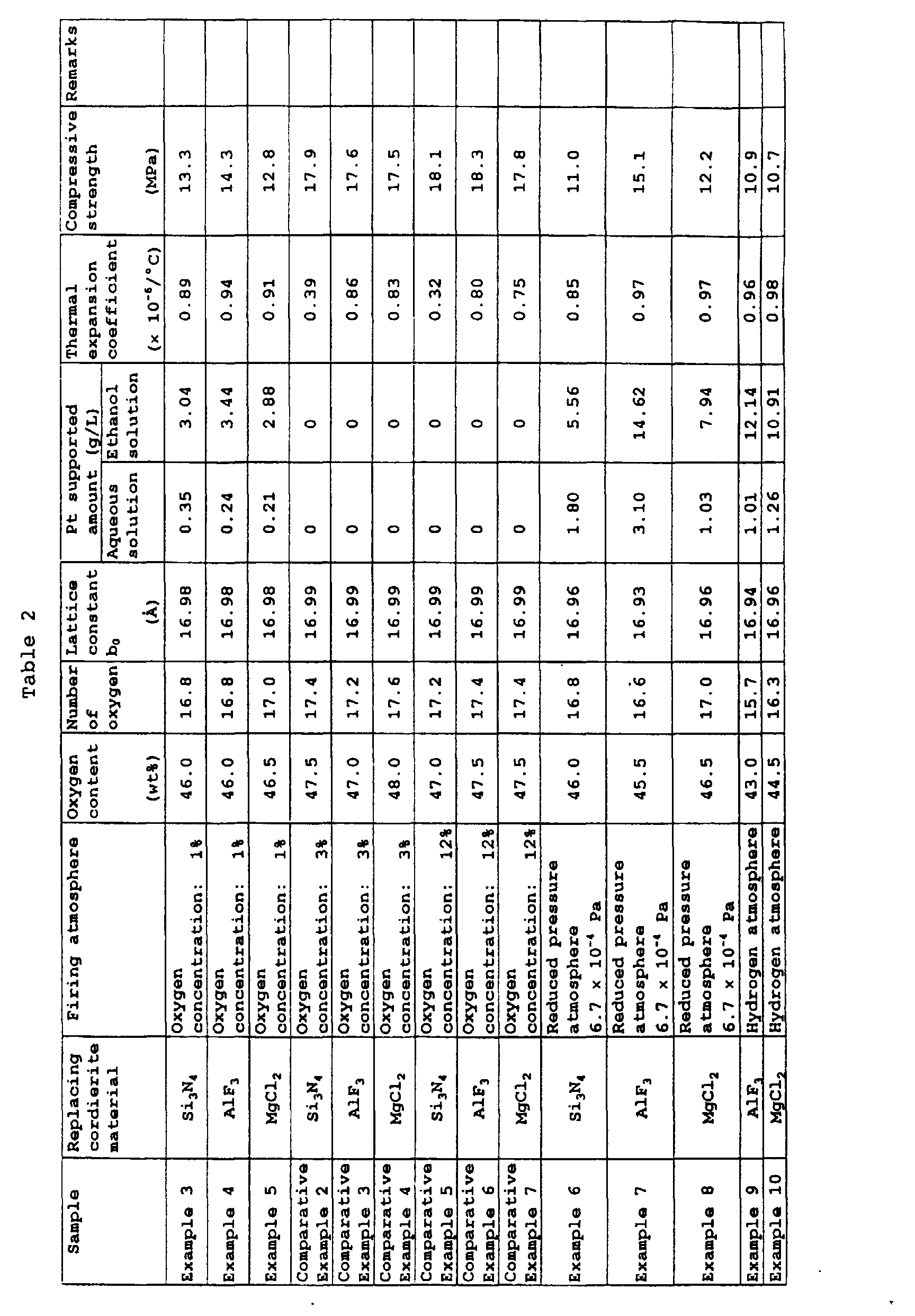
- In Examples 6 to 8, cordierite honeycomb structures were produced in the same manner as in Examples 3 to 5, except that the used firing atmosphere was a reduced pressure atmosphere having a pressure of 6.7 to 10-4 Pa (5 × 10⁻⁶ Torr).
- In Examples 9 and 10, cordierite honeycomb structures were produced in the same manner as in Example 5, except that the used firing atmosphere was a hydrogen atmosphere as a reducing atmosphere. The obtained cordierite honeycomb structures were evaluated in the same manner as in Example 1. The results are also shown in Table 2.
- As seen in Table 2, in comparison with Comparative Examples 2 to 7, the cordierite honeycomb structures produced in Examples 6 to 10 had a reduced oxygen content of the honeycomb structure, a reduced number of the oxygen contained in the unit lattice of the cordierite crystal, and a smaller lattice constant of the b0 axis of the cordierite crystal. It is therefore clear that oxygen vacancies were formed. When Pt was supported, Pt was supported in an amount of 1.01 to 3.10 g/l in the case of water as the solvent and in an amount of 5.56 to 14.62 g/l in the case of ethanol. The thermal expansion coefficient in the direction of the flow channel was 0.85 to 0.98 × 10⁻⁶/°C, and the compressive strength in the direction of the flow channel was 10.7 to 15.1 MPa, both of which satisfy the requirements.
- In Examples 11 and 12, Fe2O3 or Ca2O3 was used for 10% by weight of the Si source, and talc, kaolin, alumina and aluminum hydroxide were used as the other Si, Al and Mg sources to formulate a near theoretical cordierite composition. The thus prepared cordierite materials were formed into a honeycomb shape, heated to remove a binder and then fired at 1390°C in an air atmosphere for 2 hours to produce a cordierite honeycomb structure.
- The obtained cordierite honeycomb structures were evaluated in the same manner as before. The results are shown in Table 3.
- In Examples 13 and 14, GeO2 or MoO3, as an oxide or an element having a valence larger than Al, was used for 10% by weight of the Al source, and talc, kaolin, alumina and aluminum hydroxide were used as the other Si, Al and Mg sources to formulate a near theoretical cordierite composition. The thus prepared cordierite materials were formed into a honeycomb shape, heated and then fired in the same manner as in Example 11.
- In Examples 15 to 18, Fe2O3, Ga2O3, GeO2 or MoO3, as an oxide of an element having a valence larger than Mg, was used for 10% by weight of the Mg source, and talc, kaolin, alumina and aluminum hydroxide were used as the other Si, Al and Mg sources to formulate a near theoretical cordierite composition. The thus prepared cordierite materials were formed into a honeycomb shape, heated and then fired in the same manner as in Example 11.
- The obtained cordierite honeycomb structures were evaluated in the same manner as before. The results are also shown in Table 3.
- In Table 3, in comparison with Comparative Example 1, the cordierite honeycomb structures of Examples 11 and 12, in which some Si was replaced by an element having a smaller valence than Si, had a reduced oxygen content of the honeycomb structure, a reduced number of the oxygen contained in the unit lattice of the cordierite crystal, and a smaller lattice constant of the b0 axis of the cordierite crystal. It is therefore clear that oxygen vacancies were formed. When Pt was supported, Pt was supported in an amount of 0.15 to 0.23 g/l in the case of water as the solvent and in an amount of 2.62 to 5.31 g/l in the case of ethanol. The thermal expansion coefficient in the direction of the flow channel was 0.86 to 0.89 × 10⁻⁶/°C, and the compressive strength in the direction of the flow channel was 12.5 to 16.7 MPa, both of which satisfy the requirements.
- In comparison with Comparative Example 1, the cordierite honeycomb structures of Examples 13 to 18, in which some cordierite-constituting element Al or Mg was replaced by an element having a larger valence than Al or Mg, had an increased oxygen content of the honeycomb structure, an increased number of the oxygen contained in the unit lattice of the cordierite crystal, and a varied lattice constant of the b0 axis of the cordierite crystal. It is therefore clear that lattice defects were formed. When Pt was supported, Pt was supported in an amount of 0.27 to 1.24 g/l in the case of water as the solvent and in an amount of 0.67 to 3.69 g/l in the case of ethanol. The thermal expansion coefficient in the direction of the flow channel was 0.57 to 0.95 × 10⁻⁶/°C, and the compressive strength in the direction of the flow channel was 10.8 to 14.8 MPa, both of which satisfy the requirements.
- In Examples 19 and 20, cordierite honeycomb structures were produced in the same manner as in Examples 11 and 12, except that the used firing atmosphere was a reduced pressure atmosphere having a pressure of 6.7 to 10-4 Pa (5 × 10⁻⁶ Torr).
- In Examples 21 and 22, cordierite honeycomb structures were produced in the same manner as in Examples 11 and 12, except that the used firing atmosphere was a hydrogen atmosphere as a reducing atmosphere.
- The obtained cordierite honeycomb structures were evaluated in the same manner as in Example 1. The results are also shown in Table 3.
- As seen in Table 3, in comparison with Comparative Example 1, the cordierite honeycomb structures produced in Examples 19 and 20 had a reduced oxygen content of the honeycomb structure, a reduced number of the oxygen contained in the unit lattice of the cordierite crystal, and a smaller lattice constant of the b0 axis of the cordierite crystal. It is therefore clear that oxygen vacancies were formed. When Pt was supported, Pt was supported in an amount of 0.25 to 0.68 g/l in the case of water as the solvent and in an amount of 2.77 to 10.15 g/l in the case of ethanol. The thermal expansion coefficient in the direction of the flow channel was 0.91 to 0.98 × 10⁻⁶/°C, and the compressive strength in the direction of the flow channel was 10.0 to 11.0 MPa, both of which satisfy the requirements.
- In Example 23, a cordierite honeycomb structure was produced in the same manner as in Example 11, except that the used firing atmosphere was a nitrogen atmosphere having an oxygen concentration of 0%.
- In Example 24, a cordierite honeycomb structure was produced in the same manner as in Example 11, except that the used firing atmosphere was an oxygen atmosphere having an oxygen concentration of 100%.
- The obtained cordierite honeycomb structures were evaluated in the same manner as before. The results are also shown in Table 3.
- In comparison with the cordierite honeycomb structures in Comparative Example 1, the cordierite honeycomb structures prepared in Examples 23 and 24, where a portion of the cordierite constituting element Si was replaced by an element having a smaller valence than Si, had a reduced oxygen content of the honeycomb structure, a reduced amount of oxygen contained in the unit lattice of the cordierite crystal, and a smaller lattice constant of the b0 axis of the cordierite crystal. It is therefore clear that oxygen vacancies were formed in the cordierite crystals. Here, when Examples 23 and 24 are compared, the characteristics of the obtained cordierite honeycomb structures are not very different from each other, although the oxygen concentration was different in these Examples. Therefore, it may be concluded that the oxygen concentration of an oxygen atmosphere does not have an effect on the characteristics of the cordierite honeycomb structure.
- When Pt was supported on the cordierite honeycomb structure, the amount of Pt supported was 0.20 to 0.25 g/l in the case of water as the solvent and 3.01 to 4.98 g/l in the case of ethanol as the solvent. The thermal expansion coefficient was 0.85 to 0.90 × 10⁻⁶/°C and the compressive strength was 12.4 to 16.6 MPa, both of which satisfy the requirements.

- As the cordierite materials, talc, kaolin, alumina and aluminium hydroxide were used and formulated into a near theoretical cordierite composition. In the same manner as in Example 1, the cordierite materials were added to a binder, a lubricant and a humidicant in appropriate amounts, formed into a honeycomb shape, and then fired in air at 1390°C for 2 hours, to obtain a honeycomb structure.
- After the cordierite honeycomb structure was cooled to room temperature, the obtained cordierite honeycomb structure was subjected to a thermal shock by heating the honeycomb structure up to a temperature of the sum of the room temperature plus an intended thermal shock temperature difference followed by dropping the heated honeycomb structure into water. The thermal shock temperature difference was varied in a range of 150 to 900°C in Examples 25 to 30 as shown in Table 4.
- Also, in Examples 31 to 36, in the course of cooling from the firing temperature of 1390°C above, when the cordierite honeycomb structure was cooled to a temperature of the sum of the room temperature plus an intended thermal shock temperature difference, air was blown to the honeycomb structure in the direction of the flow channel to provide a thermal shock to the honeycomb structure. The thermal shock temperature difference was varied in a range of 150 to 900°C in Examples 31 to 36 as shown in Table 4.
- The honeycomb structures after the thermal shock were observed by TEM. It was confirmed that fine cracks having a width of 10 nm or less were formed in a large number at interfaces between the cordierite crystal phases and the amorphous phases.
- The Pt supporting amount, the thermal expansion coefficient and the compressive strength in the direction of the flow channel of the honeycomb structures were evaluated. The results are shown in Table 4.
- As seen in Table 4, the Pt supporting amount was in a range of 0.88 to 1.64 g/l in the case of water as the solvent and in a range of 3.18 to 4.77 g/l in the case of ethanol, which indicates that supporting Pt was made possible by the fine cracks. The thermal expansion coefficient was 0.28 to 0.39 × 10⁻⁶/°C, and the compressive strength in the direction of the flow channel was 13.0 to 17.0 MPa, both of which satisfy the requirements.
Sample Temperature difference of thermal shock (°C) Pt supported amount (g/L) Thermal expansion coefficient (× 10-6/°C) Compressive strength (MPa) Remark Aqueous solution Ethanol solution Example 25 150 1.35 3.43 0.29 16.8 Re-heating Example 26 300 1.57 4.22 0.29 15.9 Re-heating Example 27 450 0.88 3.18 0.32 15.1 Re-heating Example 28 600 0.90 4.26 0.37 14.2 Re-heating Example 29 750 1.44 4.61 0.37 13.6 Re-heating Example 30 900 1.06 4.77 0.36 13.0 Re-heating Example 31 150 0.98 3.33 0.29 17.0 During cooling Example 32 300 1.64 4.13 0.28 16.1 During cooling Example 33 450 1.33 3.76 0.34 15.3 During cooling Example 34 600 1.20 4.01 0.38 14.8 During cooling Example 35 750 1.03 4.35 0.37 14.0 During cooling Example 36 900 1.10 4.44 0.39 13.2 During cooling - In Example 37, Ga2O3, an oxide of an element having a smaller valence than Si, was used for 10% by weight of the Si source, and talk, kaolin, alumina and aluminum hydroxide were used as the other Si, Al and Mg sources to formulate a near theoretical cordierite composition. The thus prepared cordierite materials were formed into a honeycomb shape, heated to remove a binder and then fired at 1390°C in an air atmosphere for 2 hours to produce a cordierite honeycomb structure, in the same manner as in Example 1.
- The obtained cordierite honeycomb structure was cooled to room temperature and re-heated to 320°C, at which temperature the re-heated honeycomb structure was dropped into water for rapid cooling or applying a thermal shock. Pt was supported onto the thus treated honeycomb structure by CVD. While a carrier gas of nitrogen was flowed at 20 l/min, platinum acetylacetonate was heated and sublimated at 180°C, to adsorb Pt on the honeycomb structure for 1 hour and the honeycomb structure was then heat-treated in air at 800°C for 2 hours. The amount of Pt supported on the obtained honeycomb structure was measured to be 1.22 g/l.
- In Examples 38 and 39, GeO2, an oxide of an element having a larger valence than Al, was used for 10% by weight of the Al source, and talk, kaolin, alumina and aluminum hydroxide were used as the other Si, Al and Mg sources to formulate a near theoretical cordierite composition. The thus prepared cordierite materials were formed into a honeycomb shape, heated to remove a binder and then fired at 1390°C in an air atmosphere for 2 hours to produce a cordierite honeycomb structure, in the same manner as in Example 1. In the course of cooling from the firing temperature of 1390°C, the honeycomb structure, when the temperature became 320°C, was dropped into water (at 20°C) to apply a thermal shock.
- In Example 38, Pt was supported onto the obtained honeycomb structure by PVD, specifically sputtering. The target was Pt, the sputtering gas was Ar, the reaction pressure was 1.3 Pa, the radio frequency was 13,56 MHz, the supplied power was 100W and the sputtering time period was 10 minutes. In Example 39, Pt was supported onto the obtained honeycomb structure using a super critical fluid. The super critical fluid used was CO2 in which the honeycomb structure was immersed for 5 minutes. The amount of the supported Pt was 1.01 g/l in Example 38 and 1.55 g/l in Example 39.
- Table 5 shows the characteristics of the honeycomb structures in Examples 37 to 39, evaluated in the same manner as described before. It is seen in Table 5 that oxygen vacancies were formed because of its oxygen content, number of oxygen and lattice constant in Example 37, and lattice defects were formed because of their oxygen content, number of oxygen and lattice constant in Examples 38 and 39.
- When the honeycomb structures of Examples 37 to 39 were observed by TEM, a large number of fine cracks having a width of several nanometers or less were formed near the interfaces between the cordierite crystal phases and the amorphous phases of the honeycomb structure. Therefore, it is seen that when a cordierite-constituting element is replaced by an element having a different valence and a thermal shock is applied, both the fine pores by the oxygen vacancies or lattice defects as well as the fine pores by the fine cracks are formed.
- In Examples 37 to 39, the thermal expansion coefficient was 0.59 to 0.75 × 10⁻⁶/°C, and the compressive strength in the direction of the flow channel was 10.1 to 10.6 MPa, both of which satisfy the requirements.

- In Example 40, talc, kaolin, alumina and aluminum hydroxide were used as the Si, Al and Mg sources and were formulated into a near theoretical cordierite composition and the cordierite materials were further added with 0.05% by weight of NaCO3 as a compound of an alkali metal element. The prepared cordierite materials were formed into a honeycomb shape, heated to remove a binder and then fired at 1390°C in an air atmosphere for 2 hours to produce a cordierite honeycomb structure, in the same manner as in Example 1. The obtained cordierite honeycomb structure was rapid cooled to room temperature by dropping into water (at 20°C) from 320°C in the course of cooling from the firing at 1390°C to apply a thermal shock.
- Example 40 was repeated to produce a cordierite honeycomb structure, but the firing was carried out in a reduced pressure atmosphere having a pressure of 4000 MPa in Example 41 and in a reducing atmosphere of a hydrogen atmosphere in Example 42. The obtained cordierite honeycomb structures were cooled to room temperature (25°C) and then re-heated to 325°C and air was blown to apply a thermal shock.
- The obtained honeycomb structures were measured for their thermal expansion coefficient and compressive strength. The results are shown in Table 6. In Examples 40 to 42, the thermal expansion coefficient was 0.42 to 0.58 × 10⁻⁶/°C, and the compressive strength in the direction of the flow channel was 10.8 to 12.1 MPa, both of which satisfy the requirements.
- When the honeycomb structures of Examples 40 to 42 were observed by TEM, a large number of fine cracks having a width of several nanometers or less were formed near the interfaces between the cordierite crystal phases and the amorphous phases of the honeycomb structure.
- The honeycomb structures of Examples 40 to 42 were immersed in a solution of 0.07 mol/l-chloroplatinic acid and 0.05 mol/1-rhodium chloride in ethanol while applying an ultrasonic wave for 10 minutes. The honeycomb structures were then blown with an air flow under 1 × 10⁻⁵ Pa (1 kgf/cm2) to dry and then fired in air at 800°C for 2 hours. The thus Pt supported honeycomb structures were subjected to X-ray fluorescence spectroscopy to analyze the supported amounts of Pt and Rh. The honeycomb structure of Example 40 supported 1.2 g/l of Pt and 0.2 g/l of Rh, Example 41 supported 1.3 g/l of Pt and 0.3 g/l of Rh, and Example 42 supported 1.1 g/l of Pt and 0.2 g/l of Rh.
- For comparison, Pt and Rh were similarly supported on the honeycomb structures of Examples 29 and 35, in which a thermal shock was applied but Na2CO3 was not added. The honeycomb structure of Example 29 supported 0.7 g/l of Pt and 0.2 g/l of Rh and Example 35 supported 0.5 g/l of Pt and 0.2 g/l of Rh, which are less than the amounts of the supported Pt and Rh in Examples 40 to 42. It is considered that in Examples 40 to 42, more fine cracks were formed by the thermal shock because the amorphous phase was increased by addition of Na2CO3.
Sample Temperature difference of thermal shock (°C) Catalyst supported amount (g/L) Thermal expansion coefficient (x 10-6/°C) Compressive strength (MPa) Remarks Pt Rh Example 40 300 1.2 0.2 0.42 12.1 Na2CO3: 0.5 wt% addition Firing in air During cooling Example 41 300 1.3 0.3 0.58 11.3 Na2CO3: 0.5 wt% addition Reduced pressure atmosphere Re-heating Example 42 300 1.1 0.2 0.52 10.8 Na2CO3: 0.5 wt% addition Firing in reducing atmosphere Re-heating Example 43 - 1.9 0.2 0.38 10.6 Firing in air Ultrasonic wave application - As the cordierite materials, talc, kaolin, alumina and aluminium hydroxide were used and formulated into a near theoretical cordierite composition. In the same manner as in Example 1, the cordierite materials were added to a binder, a lubricant and a humidicant in appropriate amounts, formed into a honeycomb shape, and then fired in air at 1390°C for 2 hours, to obtain a honeycomb structure. A shock wave of a focused ultrasound with a frequency of 29 kHz and a power of 100W was applied to the obtained honeycomb structure. In the same manner as in Examples 40 to 42, catalyst components (Pt and Rh) were supported on the obtained cordierite honeycomb structure and the amounts of the supported Pt and Rh were measured. Also, the thermal expansion coefficient and the compressive strength in the direction of the flow channel were measured. The results are shown in Table 6.
- As seen in Table 6, the amount of the supported Pt was 1.9 g/l and the amount of the supported Rh was 0.2 g/l.
- The thermal expansion coefficient was 0.38 × 10⁻⁶/°C, and the compressive strength in the direction of the flow channel was 10.6 MPa, both of which satisfy the requirements.
- By observing the honeycomb structure, it was confirmed that fine cracks having a width of a few nanometers were formed in a large number at interfaces between the cordierite crystal phases and the amorphous phases.
- As the cordierite materials, talc, kaolin, alumina and aluminium hydroxide were used and formulated into a near theoretical cordierite composition. In the same manner as in Example 1, the cordierite materials were added to a binder, a lubricant and a humidicant in appropriate amounts, formed into a honeycomb shape, and then fired in air at 1390°C for 2 hours, to obtain honeycomb structures.
- The obtained honeycomb structure was immersed in high temperature and high pressure water at 10 MPa and 300°C for 1 hour in Example 44. Similarly, the obtained honeycomb structure was immersed in super critical fluid CO2 for 30 minutes in Example 45, and in an aqueous solution of sodium hydroxide of 1 mol/l at 60°C for 5 hours in Example 46.
- The amounts of the supported catalyst components (Pt and Rh), the thermal expansion coefficient and the compressive strength in the direction of the flow channel were measured. The results are shown in Table 7.
- In Examples 44 to 46, the amount of the supported Pt was 1.5 to 2.3 g/l, the amount of the supported Rh was 0.2 to 0.3 g/l, confirming that fine pores capable to support a catalyst component were formed. The thermal expansion coefficient was 0.35 to 0.39 × 10⁻⁶/°C, and the compressive strength in the direction of the flow channel was 11.2 to 12.2 MPa, both of which satisfy the requirements.
Sample Treatment condition Catalyst supported amount (g/L) Thermal expansion coefficient (x 10-6/°C) Compressive strength (MPa) Remarks Pt Rh Example 44 High temperature and high pressure water (10 MPa, 300°C) 1.5 0.3 0.39 11.9 Firing in air Example 45 Super critical fluid (CO2) 2.3 0.3 0.37 11.2 Firing in air Example 46 Aqueous solution of sodium hydroxide (1 mol/L, 60°C) 2.1 0.2 0.35 12.2 Firing in air - As the cordierite materials, talc, kaolin, alumina and aluminium hydroxide were used and formulated into a near theoretical cordierite composition. In the same manner as in Example 1, the cordierite materials were added with a binder, a lubricant and a humidicant,in appropriate amounts, formed into a honeycomb shape, and then fired in air at 1390°C for 2 hours, to obtain honeycomb structures.
- In Example 47, the obtained honeycomb structure was dry etched with CF4. The conditions of the dry etching was a CF4 flow rate of 150 ml/min, a reaction chamber pressure of 13.3 Pa, an applied radio frequency of 13.56 MHz, a supplied power of 300W and an etching duration of 10 minutes. In Example 48, similarly, dry etching was carried out with Ar under the conditions of a reaction chamber pressure of 1.3 Pa, an applied radio frequency of 13.56 MHz, a supplied power of 100W and an etching duration of 10 minutes.
- The amounts of the supported catalyst components (Pt and Rh), the thermal expansion coefficient and the compressive strength in the direction of the flow channel were measured. The results are shown in Table 8.
- In Examples 47 to 48, the amount of the supported Pt was 1.1 to 1.3 g/l, and the amount of the supported Rh was 0.2 to 0.3 g/l, confirming that fine pores capable to support a catalyst component were formed. The thermal expansion coefficient was 0.45 to 0.46 × 10⁻⁶/°C, and the compressive strength in the direction of the flow channel was 11.7 to 12.7 MPa, both of which satisfy the requirements.
- The results of the evaluation of Examples 47 and 48 are shown in Table 8.
Sample Treatment condition Catalyst supported amount (g/L) Thermal expansion coefficient (× 10-6/°C) Compressive strength (MPa) Remarks Pt Rh Example 41 Dry etching (CF4) 1.1 0.3 0.46 11.7 Firing in air Example 48 Sputter etching (Ar) 1.3 0.2 0.45 12.7 Firing in air - In Example 49, as the cordierite materials, talc, kaolin, alumina and aluminium hydroxide were used, but 5% by weight of the Si source was replaced by CeO2, and formulated into a near theoretical cordierite composition. In the same manner as in Example 1, the cordierite materials were added with a binder, a lubricant and a humidicant in appropriate amounts, formed into a honeycomb shape, heated in air to 800°C to remove the binder and then fired in a reduced pressure atmosphere under 4000 MPa at 1390°C for 2 hours, to obtain a cordierite honeycomb structure.
- In Example 50, a cordierite honeycomb structure was produced in the similar manner as in Example 49, but 5% by weight of the Al source, not the Si source, was replaced by CeO2 and the firing atmosphere was a reducing atmosphere of a hydrogen atmosphere.
- In Example 51, a cordierite honeycomb structure was produced in the similar manner as in Example 49, but 5% by weight of the Mg source, not the Si source, was replaced by CeO2 and the firing atmosphere was an air atmosphere.
- The obtained cordierite honeycomb structures were evaluated in their thermal expansion coefficient and the compressive strength in the direction of the flow channel.
- As seen in Table 9, the thermal expansion coefficient was 0.78 to 0.98 × 10⁻⁶/°C, and the compressive strength in the direction of the flow channel was 10.8 to 12.1 MPa, both of which satisfy the requirements.
- When catalyst components (Pt and Rh) were supported on the honeycomb structures of Examples 49 to 51, the amounts of the supported Pt and Rh were 1.5 to 2.3 g/l of Pt and 0.2 to 0.3 g/l of Rh, confirming that fine pores capable of supporting a catalyst component were formed by incorporating CeO2 in the cordierite honeycomb structure. The amount of the supported catalyst components of Examples 49 to 51 is equivalent to that in the three way converter catalyst (1.5 g/l).
- The results of the evaluation in Examples 49 to 51 are shown in Table 9.

- The oxygen storage capacity of the cordierite honeycomb structures of Examples 49 to 51 was evaluated. The evaluation of the oxygen storage capacity was made by TG-DTA (Rigaku: TAS-200). The produced Ce-substituted cordierite honeycomb structures were pulverized, and 20 mg of the pulverized powder was kept at 500°C, while an oxygen atmosphere of 50% of O2, with the balance being N2, and a reducing atmosphere of 2% of H2, with the balance being N2, were repeated twice. The amount of the released oxygen was calculated from the weight difference between the oxygen atmosphere and the reducing atmosphere. This amount of the released oxygen was divided by the amount of the CeO2 contained in the cordierite honeycomb structure to obtain the amount of the released oxygen per 1 mol of CeO2 contained in the cordierite honeycomb structure, that is, the oxygen storage capacity. The oxygen storage capacity is also shown in Table 9.
- For comparison, the oxygen storage capacity of a cordierite honeycomb structure without a Ce substitution was also evaluated and that of a three way converter catalyst with CeO2 supported thereon, in which the amount of the supported CeO2 was made to be 75 g/l, 1.5 times the usual supported amount, was also evaluated. As a result, the cordierite honeycomb structure without a Ce substitution did not have an oxygen storage capacity and the three way converter catalyst with CeO2 supported thereon had an oxygen storage capacity of 1.5 × 10⁻²O2 mol/CeO2 mol. In contrast, the oxygen storage capacities of Examples 49 to 51 were in a range of 3.1 to 9.6 × 10⁻²O2 mol/ceO2 mol, which was larger than that of the three way catalyst.
- The content of CeO2 in Example 51, having the highest oxygen storage capacity, was only about 2% by weight. The amount of the oxygen which can be stored by 1 liter of the cordierite honeycomb structure of Example 51 and that by 1 liter of the three way catalyst (75 g/l of the supported CeO2) were almost equal to each other. The experiment of Example 51, in which Mg was replaced by Ce, was repeated and the content of CeO2 in the cordierite honeycomb structure of Example 51 was varied. The oxygen storage capacity was significantly reduced, to a level where it was difficult to detect, when the content of CeO2 in the cordierite honeycomb structure was 0.01% by weight. Accordingly, at least 0.01% by weight of the content of CeO2 is necessary to provide an oxygen storage capacity.
- In Example 52, as the cordierite materials, talc, kaolin, alumina and aluminium hydroxide were used but 1.2% by weight of the Mg source was replaced by Pt, and they were formulated into a near-theoretical cordierite composition. In the same manner as in Example 1, the cordierite materials were added with a binder, a lubricant and a humidicant in appropriate amounts, formed into a honeycomb shape and then fired in an air atmosphere at 1390°C for 2 hours, to obtain a cordierite honeycomb structure.
- The obtained cordierite honeycomb structure had a Pt content of 1.7 g/l. The cordierite honeycomb structure was evaluated in its thermal expansion coefficient and the compressive strength in the direction of the flow channel. As seen in Table 10, the thermal expansion coefficient was 0.85 × 10⁻⁶/°C, and the compressive strength in the direction of the flow channel was 10.9 MPa, both of which satisfy the requirements.
- In Example 53, a cordierite honeycomb structure was produced in the similar manner as in Example 52, but 1.2% by weight of the Mg source was replaced with an oxide of Pt and 5% by weight of the Al source was replaced by CeO2. After being cooled to room temperature, the honeycomb structure was re-heated to 320°C and rapidly cooled by being dropped into water (20°C).
- The obtained cordierite honeycomb structures had a Pt content of 1.6 g/l and an oxygen storage capacity of 3.9 × 10⁻²O2 mol/CeO2 mol. The cordierite honeycomb structure was evaluated in its thermal expansion coefficient and the compressive strength in the direction of the flow channel. As seen in Table 10, the thermal expansion coefficient was 0.96 × 10⁻⁶/°C, and the compressive strength in the direction of the flow channel was 11.9 MPa, both of which satisfy the requirements.
- The results of the evaluation of Examples 52 and 53 are shown in Table 10.

- The performance of the thus produced cordierite honeycomb structures in cleaning hydrocarbon was evaluated.
- A catalyst component was supported on each of the cordierite honeycomb structures produced in Examples 1, 11 to 18, 25 to 33 and 40 to 53, to form a catalyst-ceramic body. The catalyst-ceramic body was cut out into a cylinder having a diameter of 15 mm and a length of 10 mm. The cylinder of the catalyst-ceramic body was used in the test of cleaning hydrocarbon at various predetermined temperatures in a model gas bench. The model gas comprised 500 ppm of C3H6, 5% of oxygen and the balance being nitrogen. The SV (space velocity) was 10,000/hour. The temperature at which 50% of C3H6 in the model gas was cleaned with a catalyst-ceramic body, was made as "50% cleaning temperature". The results are shown in Table 11.
Sample 50% cleaning temperature (°C) Catalyst supported amount (g/L) Supporting method Remarks Pt Rh Comparative Example 8 489 - - - No catalyst Comparative Example 9 184 1.25 0.25 - Three way convertor catalyst Example 1 188 1.9 - Ethanol solution Example 11 263 7.7 - Ethanol solution Example 12 233 2.3 - Ethanol solution Example 13 255 8.8 - Ethanol solution Example 14 221 2.5 - Ethanol solution Example 15 238 2.4 - Ethanol solution Example 16 263 2.0 - Ethanol solution Example 17 238 4.4 - Ethanol solution Example 18 187 2.4 - Ethanol solution Example 25 223 1.2 - CVD Example 26 233 1.0 - PVD Example 27 212 1.5 - Super critical fluid Example 28 204 3.7 - Ethanol solution Example 29 206 4.1 - Ethanol solution Example 30 190 2.6 - Ethanol solution Example 31 194 4.1 - Ethanol solution Example 32 206 3.4 - Ethanol solution Example 33 195 3.8 - Ethanol solution Example 40 221 1.2 0.2 Ethanol solution + ultrasonic wave Example 41 202 1.3 0.3 Ethanol solution + ultrasonic wave Example 42 206 1.1 0.2 Ethanol solution + ultrasonic wave Example 43 199 1.9 0.2 Ethanol solution + ultrasonic wave Example 44 207 1.5 0.3 Ethanol solution + ultrasonic wave Example 45 200 2.3 0.3 Ethanol solution + ultrasonic wave Example 46 230 2.1 0.2 Ethanol solution + ultrasonic wave Example 47 219 1.1 0.3 Ethanol solution + ultrasonic wave + Example 48 211 1.3 0.2 Ethanol solution + ultrasonic wave Example 49 214 0.6 0.5 Ethanol solution + ultrasonic wave Example 50 226 1.8 1.1 Ethanol solution + ultrasonic wave Example 51 210 1.3 0.2 Ethanol solution + ultrasonic wave Example 52 253 1.7 - - Example 53 247 1.6 - - - For comparison, the test device without the above catalyst-ceramic body was evaluated (Comparative Example 8), and a three way catalyst comprising a cordierite honeycomb structure with a coating of γ-alumina in an amount of 150 g/l on which 1/25 g/l of Pt and 0.25 g/l of Rh as well as 75 g/l of a co-catalyst CeO2 Were supported (Comparative Example 9) was also evaluated. The results are also shown in Table 11.
- As seen in Table 11, the 50% cleaning temperature was high, 500°C, in the case of Comparative Example 8 in which no catalyst-ceramic body was used, and was lowered to 184°C in the case of the three way catalyst in Comparative Example 9. In contrast, in the cases of Examples of the present invention in which the amount of the supported catalyst component was as much as that of the three way catalyst, the 50% cleaning temperature was equivalent to or slightly higher than that of the three way catalyst, and was about a half of that of the case of non-catalyst-ceramic body. Thus, a high cleaning capability was attained in the Examples.
- The relationship between the cleaning capability and the state of the supported catalyst component was examined as below:
- Cordierite materials, in which 10% by weight of the Si source was replaced by an oxide of an element having a valence different from Si, Ga2O3, was prepared, formed into a honeycomb shape, and fired in air at 1390°C for 2 hours. To the obtained honeycomb structure, catalyst components were supported by immersing in an ethanol solution of 0.07 mol/l of chloroplatinic acid and 0.05 mol/l of rhodium chloride, while ultrasound was being applied, for 10 minutes, drying and firing in air at 800°C for 2 hours, to form a catalyst-ceramic body (Sample 1). A similar sample prepared without applying ultrasound was made as Sample 2. Sample 2 was heat treated at 1000°C for 50 hours and the thus heat deteriorated sample was made as Sample 3.
- The Samples 1 to 3 were observed by TEM to examine the state of the supported catalyst metal particles. The TEN magnification was ×200,000. The spacing between the catalyst metal particles was measured for 30 particles in one field of view and the measurement was conducted for 5 fields of view to obtain an average spacing between the catalyst metal particles. The results are shown in Table 12.
- The 50% cleaning temperature of C3H6 was also measured for Samples 1 to 3. They were 254°C, 336°C and 460°C.
- Similarly, the same ceramic support as in Samples 1 to 3 was used and immersed in an aqueous solution of 0.005 mol/l of chloroplatinic acid and 0.003 mol/l of rhodium chloride, dried and fired in air at 800°C for 2 hours, to form a catalyst-ceramic body (Sample 4). Also, the same ceramic support was immersed in an aqueous solution of 0.0025 mol/l of chloroplatinic acid and 0.0015 mol/l of rhodium chloride, dried and fired in air at 800°C for 2 hours, to form a catalyst-ceramic body (Sample 5). No ultrasound was applied for Samples 4 and 5 during the supporting of the catalyst component.
- The Samples 4 and 5 were observed by TEM at the magnitude of ×50,000. The spacing between the catalyst metal particles was measured in the same manner as for Samples 1 to 3 and the results are also shown in Table 12.
Sample No. 1 2 3 4 5 50% cleaning temperature (°C) 254 336 460 472 484 Average spacing between catalyst metal particles (nm) 23 74 108 850 1009 - In Table 12, Sample 3, which was deteriorated by heating, had a 50% cleaning temperature of C2H6 of 460°C and an average spacing between the catalyst metal particles of 108 nm, beyond 100 nm. As seen in Table 11, the 50% cleaning temperature of C3H6 by a non-catalyst-ceramic body was 484°C and, therefore, Sample 3 is considered to have a cleaning capability.
- Sample 2 had a 50% cleaning temperature of C3H6 of 336°C and an average spacing between the catalyst metal particles of 74 nm, while Sample 1 had a 50% cleaning temperature of C3H6 of 254°C and an average spacing between the catalyst metal particles of 23 nm. It is seen that as in the average spacing between the catalyst metal particles decreased, the 50% cleaning temperature lowered.
- Sample 4, having an average spacing between the catalyst metal particles of less than 1000 nm, had a 50% cleaning temperature of C3H6 of 472°C, lower than 484°C of the non-catalyst-ceramic body, indicating that Sample 4 had a cleaning capability.
- However, Sample 5, having an average spacing between the catalyst metal particles of more than 1000 nm, had a 50% cleaning temperature of 484°C, equal to that of the non-catalyst-ceramic body, indicating that Sample 5 did not have a cleaning capability.
- Therefore, it can be seen that the average spacing between the catalyst metal particles should be not more than 1000 nm, preferably not more than 100 nm to have a cleaning capability. With a smaller average spacing between the catalyst metal particles, the cleaning capability is improved. When using ultrasound during the supporting step, the catalyst component can be more easily infiltrated in the fine pores of the ceramic support and the average spacing between the catalyst metal particles can be decreased.
Claims (103)
- A ceramic support which comprises a crystal lattice having at least one of oxygen vacancy and lattice defects therein, by which said ceramic support can support a catalyst component.
- The ceramic support according to claim 1, wherein said ceramic support has a shape of at least one of a honeycomb, a pellet and a powder.
- A ceramic support which has cracks by which said ceramic support can support a catalyst component.
- The ceramic support according to claim 4, wherein said cracks are present in at least one of the crystal and the amorphous phases.
- The ceramic support according to claim 3 or 4, wherein said cracks have a width in a range of 100 nm or less.
- The ceramic support according to any one of claims 3 to 5, wherein said ceramic support has a shape of at least one of a honeycomb, a pellet and a powder.
- A ceramic support capable of supporting a catalyst, comprising a ceramic body having fine pores with a diameter or width of up to 1000 times the ion diameter of a catalyst component to be supported on the surface of said ceramic body, the number of said fine pores being not less than 1 × 10¹¹ pores per liter.
- The ceramic support according to claim 7, wherein said ceramic body has five pores with a diameter or width of 1 to 1000 times the ion diameter of a catalyst component to be supported on the surface of said ceramic body.
- The ceramic support according to claim 7 or 8, wherein said number of said fine pores is not less than 1 × 10¹⁶ pores per liter.
- The ceramic support according to any one of claims 7 to 9, wherein said fine pores are composed of at least ones of oxygen vacancies and lattice defects in the crystal lattice of said ceramic, fine cracks on the surface of said ceramic body, and vacancies of an element or elements constituting the ceramic.
- The ceramic support according to any one of claims 7 to 10, wherein said ceramic mainly comprises cordierite.
- The ceramic support according to any one of claims 7 to 11, wherein said ceramic support is in the form of a honeycomb.
- The ceramic support according to any one of claims 7 to 12, wherein said ceramic support has a compressive strength in the direction of the flow channel of not less than 1 MPa and a thermal expansion coefficient in the direction of the flow channel of not higher than 1.0 × 10⁻⁶/°C.
- The ceramic support according to claim 13, wherein said ceramic support has a compressive strength in the direction of the flow channel of not less than 10 MPa.
- The ceramic support according to any one of claims 7 to 14, wherein said ceramic support has the fine pores in a number of not less than 1 × 10¹⁷ pores per liter.
- The ceramic support according to any one of claims 7 to 15, wherein said diameter or width of said fine pores is in a range of 0.1 to 100 nm.
- The ceramic support according to any one of claims 7 to 16, wherein said fine pores have a depth of not smaller than a half of the ion diameter of a catalyst component to be supported on the surface of said ceramic body.
- The ceramic support according to any one of claims 11 to 16, wherein said ceramic has a content of oxygen in an amount of less than 47% by weight or more than 48% by weight.
- The ceramic support according to any one of claims 11 to 16, wherein said ceramic comprises cordierite crystals and the lattice constant of b0 axis of the cordierite crystals is larger than 16.99 or smaller than 16.99.
- The ceramic support according to any one of claims 11 to 16, wherein said ceramic includes cordierite crystals having one or more of at least one of oxygen vacancy and lattice defect in the unit lattice of cordierite crystal in an amount of not less than 4 × 10⁻⁸% of said ceramic.
- The ceramic support according to claim 20, wherein said ceramic includes said cordierite crystals having one or more of at least one of oxygen vacancy and lattice defect in the unit lattice of cordierite crystal in an amount of not less than 4 × 10⁻⁵% of said ceramic.
- The ceramic support according to any one of claims 7 to 16, wherein said ceramic comprises cordierite crystals which comprise not less than 4 × 10⁻⁸ of at least one of oxygen vacancy and lattice defect per unit lattice of cordierite crystal.
- The ceramic support according to claim 22, wherein said ceramic comprises cordierite crystals which comprise not less than 4 × 10⁻⁷ of at least one of oxygen vacancy and lattice defect per unit lattice of cordierite crystal.
- A ceramic support capable of supporting a catalyst component, comprising a honeycomb structure mainly comprised of a cordierite composition and having oxygen vacancies in cordierite crystals, said honeycomb structure having a content of oxygen in an amount of less than 47% by weight.
- The ceramic support according to claim 24, wherein said oxygen vacancies are formed by firing in a reduced pressure atmosphere, a reducing atmosphere, or a low oxygen concentration atmosphere.
- The ceramic support according to claim 25, wherein said firing atmosphere is a reduced pressure atmosphere at a pressure of not higher than 4000 Pa, a reducing atmosphere, or a low oxygen concentration atmosphere with a oxygen concentration in a range of not less than 0% and up to less than 3%.
- The ceramic support according to claim 24, wherein said oxygen vacancies are formed by replacing at least some of Si, Al and Mg elements constituting the cordierite by an element having a valency smaller than that of the replaced element.
- The ceramic support according to any one of claims 24 to 27, wherein said cordierite crystals have a lattice constant of b0 axis of smaller than 16.99.
- A ceramic support capable of supporting a catalyst component, comprising a honeycomb structure mainly comprised of a cordierite composition and having lattice defects in cordierite crystals, said honeycomb structure having a content of oxygen in an amount of more than 48% by weight.
- The ceramic support according to claim 29, wherein said lattice defects are formed by replacing at least some of Si, Al and Mg elements constituting the cordierite by an element having a valency greater than that of the replaced element.
- The ceramic support according to claim 29 or 30, wherein said cordierite crystals have a lattice constant of the b0 axis of larger than 16.99 or smaller than 16.99.
- A ceramic support capable of supporting a catalyst component, comprising a honeycomb structure mainly comprised of a cordierite composition and having a multiple number of fine cracks in at least one of the amorphous and the crystal phases thereof.
- The ceramic support according to claim 32, wherein said ceramic support contains an alkali metal and an alkaline earth metal in a total amount of not less than 0.05% by weight.
- The ceramic support according to claim 32 or 33, wherein said fine cracks have a width of not more than 100 nm and said fine cracks are formed by thermal shock or shock waves.
- A ceramic support capable of supporting a catalyst component, comprising a honeycomb structure mainly comprised of a cordierite composition and having at least ones of oxygen vacancies and lattice defects as well as having a multiple number of fine cracks in at least one of the amorphous and the crystal phases thereof.
- The ceramic support according to any one of claims 32 to 35, wherein said honeycomb structure includes said oxygen vacancies, lattice defects and fine cracks in a total number amount of at least 1 × 10¹⁶ per liter.
- A ceramic support capable of supporting a catalyst component, comprising a honeycomb structure mainly comprised of a cordierite composition, said honeycomb structure having an oxygen content of less than 47% by weight or more than 48% by weight and a multiple number of fine cracks in at least one of the amorphous and the crystal phases thereof.
- A ceramic support capable of supporting a catalyst component, comprising a honeycomb structure mainly comprised of a cordierite composition, a lattice constant of b0 axis of the cordierite crystals of said honeycomb structure being larger than 16.99 or smaller than 16.99, said honeycomb structure having a multiple number of fine cracks in at least one of the amorphous and the crystal phases thereof.
- A process for producing a ceramic support capable of supporting a catalyst component, comprising the step of:preparing cordierite materials comprising an Si source, an Al source and a Mg source as well as a binder,forming said cordierite materials into a honeycomb shape,heating said honeycomb shape to remove said binder and thenfiring said honeycomb shape in a reduced pressure or reducing atmosphere to form a honeycomb structure mainly comprised of a cordierite composition.
- The process according to claim 39, wherein said firing atmosphere is a reduced pressure atmosphere at a pressure of not higher than 4000 Pa, or a reducing atmosphere.
- A process for producing a ceramic support capable of supporting a catalyst component, comprising the step of:preparing cordierite materials comprising an Si source, an Al source and a Mg source as well as a binder, at least some of said Si, Al and Mg sources being used from compounds which do not comprise oxygen,forming said cordierite materials into a honeycomb shape,heating said honeycomb shape to remove said binder and thenfiring said honeycomb shape in a low oxygen concentration atmosphere with a oxygen concentration in a range of not less than 0% to less than 3% to form a honeycomb structure mainly comprised of a cordierite composition.
- A process for producing a ceramic support capable of supporting a catalyst component, comprising the step of:preparing cordierite materials comprising an Si source, an Al source and a Mg source as well as a binder, some of said Si, Al and Mg sources being replaced by compounds comprising an element having a valency smaller than that of the replaced Si, Al or Mg,forming said cordierite materials into a honeycomb shape,heating said honeycomb shape to remove said binder and thenfiring said honeycomb shape in a reduced pressure atmosphere, a reducing atmosphere, an oxygen-containing atmosphere or an oxygen-free atmosphere to form a honeycomb structure mainly comprised of a cordierite composition.
- The process according to claim 42, wherein said firing atmosphere is a reduced pressure atmosphere at a pressure of not higher than 4000 Pa, a reducing atmosphere, an oxygen-containing atmosphere or an oxygen-free atmosphere.
- A process for producing a ceramic support capable of supporting a catalyst component, comprising the step of:preparing cordierite materials comprising an Si source, an Al source and a Mg source as well as a binder, some of said Si, Al and Mg sources being replaced by compounds comprising an element having a valency larger than that of the replaced Si, Al or Mg,forming said cordierite materials into a honeycomb shape, andfiring said honeycomb shape in air to form a honeycomb structure mainly comprised of a cordierite composition.
- A process for producing a ceramic support capable of supporting a catalyst component, comprising the step of:preparing cordierite materials comprising an Si source, an Al source and a Mg source as well as a binder,forming said cordierite materials into a honeycomb shape,firing said honeycomb shape to form a honeycomb structure mainly comprised of a cordierite composition, andheating said honeycomb structure to a predetermined temperature followed by rapid cooling said honeycomb shape from said predetermined temperature.
- A process for producing a ceramic support capable of supporting a catalyst component, comprising the step of:preparing cordierite materials comprising an Si source, an Al source and a Mg source as well as a binder,forming said cordierite materials into a honeycomb shape,firing said honeycomb shape, andrapidly cooling said fired honeycomb shape from a predetermined temperature during cooling from the temperature used in said firing to form a honeycomb structure mainly comprised of a cordierite composition.
- The process according to any one of claims 39 to 44, wherein said obtained fired honeycomb structure is further heated to a predetermined temperature and then rapidly cooled from said predetermined temperature.
- The process according to any one of claims 39 to 44, wherein said obtained fired honeycomb structure is further rapidly cooled from a predetermined temperature during cooling from the temperature used in said firing.
- The process according to any one of claims 45 to 48, wherein a temperature difference between said predetermined temperature and a temperature after said rapid cooling is not more than 900°C.
- The process according to any one of claims 39 to 44, wherein said obtained fired honeycomb structure is further subjected to a shock wave.
- The process according to claim 50, wherein said shock wave is provided by ultrasound or vibration.
- The process according to any one of claims 39 to 51, wherein a compound of an alkali metal element or alkaline earth metal element is added to said cordierite materials.
- A process for producing a ceramic support capable of supporting a catalyst component, comprising the step of:preparing cordierite materials comprising an Si source, an Al source and a Mg source as well as a binder,forming said cordierite materials into a honeycomb shape,firing said honeycomb shape to form a honeycomb structure mainly comprised of a cordierite composition, andimmersing said honeycomb structure in a high temperature and high pressure water, a super critical fluid or an alkali solution.
- A process for producing a ceramic support capable of supporting a catalyst component, comprising the step of:preparing cordierite materials comprising an Si source, an Al source and a Mg source as well as a binder,forming said cordierite materials into a honeycomb shape,firing said honeycomb shape to form a honeycomb structure mainly comprised of a cordierite composition, anddry etching or sputter etching said honeycomb structure.
- A ceramic support capable of supporting a catalyst component, comprising a honeycomb structure and comprising a substance having an oxygen storage capacity.
- The ceramic support according to claim 55, wherein said ceramic support comprises CeO2 as said substance having an oxygen storage capacity in an amount of not less than 0.01% by weight.
- The ceramic support according to claim 55 or 56, wherein said honeycomb structure is mainly comprised of a cordierite composition.
- A ceramic support capable of supporting a catalyst component, comprising a honeycomb structure mainly comprised of a cordierite composition, in which some of at least one of Si, Al and Mg elements constituting cordierite is replaced by Ce.
- The ceramic support according to any one of claims 7 to 38, wherein a co-catalyst having an oxygen storage capacity is supported by said ceramic support without a coating layer being formed on the surface of said ceramic support, to provide an oxygen storage capacity.
- The ceramic support according to any one of claims 7 to 38, wherein a precursor to a co-catalyst having an oxygen storage capacity is provided to said ceramic support without a coating layer being formed on the surface of said ceramic support, and said ceramic support with said precursor is then heated to provide an oxygen storage capacity to said ceramic support.
- The ceramic support according to any one of claims 55 to 60, wherein said cordierite includes at least ones of oxygen vacancies and lattice defects in the cordierite crystal lattice.
- The ceramic support according to any one of claims 55 to 61, wherein said ceramic support has a multiple number of fine cracks in at least one of the amorphous and the crystal phases thereof.
- The ceramic support according to any one of claims 55 to 60, wherein said fine cracks have a width of not more than 100 nm.
- A process for producing a ceramic support capable of supporting a catalyst component, comprising the step of:preparing cordierite materials comprising an Si source, an Al source and a Mg source as well as a binder, some of said Si, Al and Mg sources being replaced by a Ce-containing compound,forming said cordierite materials into a honeycomb shape,heating said honeycomb shape to remove said binder, andfiring said honeycomb shape in a reduced pressure atmosphere at a pressure of not higher than 4000 Pa, a reducing atmosphere, an oxygen-containing atmosphere or an oxygen-free atmosphere to form a honeycomb structure mainly comprised of a cordierite composition.
- The process according to claim 64, wherein said obtained fired honeycomb structure is further heated to a predetermined temperature and then rapidly cooled from said predetermined temperature.
- The process according to claim 64, wherein said obtained fired honeycomb structure is further rapidly cooled from a predetermined temperature during cooling after said firing.
- The process according to claim 65 or 66, wherein a temperature difference between said predetermined temperature and a temperature after said rapid cooling is not more than 900°C.
- The process according to claim 64, wherein said obtained fired honeycomb structure is further subjected to a shock wave.
- The process according to claim 68, wherein said shock wave is provided by ultrasound or vibration.
- The ceramic support according to any one of claims 39 to 49, wherein a co-catalyst having an oxygen storage capacity is supported by said ceramic support without a coating layer being formed on the surface of said ceramic support, to provide an oxygen storage capacity.
- The ceramic support according to any one of claims 39 to 48, wherein a precursor to a co-catalyst having an oxygen storage capacity is provided to said ceramic support without a coating layer being formed on the surface of said ceramic support, and said ceramic support with said precursor then being heated to provide an oxygen storage capacity to said ceramic support.
- A catalyst-ceramic body, comprising a catalyst component supported by said ceramic support as set forth in any one of claims 7 to 38 and 55 to 63.
- A catalyst-ceramic body comprising a catalyst component directly supported on a ceramic support without a coating layer on the surface thereof.
- The catalyst-ceramic body according to claim 73, wherein said catalyst-ceramic body comprises a catalyst component in an amount as the metal element of not less than 0.01% by weight, an average distance between particles of said catalyst component on the surface of said ceramic support being in a range of 0.1 to 1000 nm.
- The catalyst-ceramic body according to claim 73 or 74, wherein said average distance between particles of said crystal component is in a range of 0.1 to 100 nm.
- The catalyst-ceramic body according to claim 73, 74 or 75, wherein said catalyst component is at least one of metals having a catalyst activity and metal oxides having a catalyst activity.
- The catalyst-ceramic body according to claim 76, wherein said metals having a catalyst activity are noble metals and said metal oxides having a catalyst activity are oxides containing at least one metal selected from the group of V, Nb, Ta, Cr, Mo, W, Mn, Fe, Co, Ni, Cu, Zn, Ga, Sn and Pb.
- The catalyst-ceramic body according to any one of claims 72 to 77, wherein said ceramic support has a multiple number of fine pores with a diameter or width of 0.1 to 100 nm on the surface thereof.
- The catalyst-ceramic body according to any one of claims 73 to 78, wherein said ceramic support is the ceramic support as set forth in any one of claims 7 to 38 and 55 to 63.
- A catalyst-ceramic body comprising a ceramic support comprising a honeycomb structure mainly comprised of a cordierite composition, some of at least one of Si, Al and Mg elements constituting the cordierite being replaced by a metal having a catalyst activity.
- The catalyst-ceramic body according to claim 80, wherein said catalyst-ceramic body contains a metal having a catalyst activity in an amount of not less than 0.01% by weight thereof.
- The catalyst-ceramic body according to claim 80, wherein said catalyst-ceramic body contains a metal having a catalyst activity in an amount of not less than 0.01% by weight thereof and CeO2 in an amount of not less than 0.01% by weight thereof.
- The catalyst-ceramic body according to any one of claims 80 to 82, wherein said metal having a catalyst activity is at least one of noble metals, V, Nb, Ta, Cr, Mo, W, Mn, Fe, Co, Ni, Cu, Zn, Ga, Sn and Pb.
- The catalyst-ceramic body according to any one of claims 80 to 83, wherein said honeycomb structure has at least ones of oxygen vacancies and lattice defects in the cordierite crystal lattice, on which a catalyst component is supported.
- The catalyst-ceramic body according to any one of claims 80 to 84, wherein said honeycomb structure has a multiple number of fine cracks in at least one of the amorphous and the crystal phases thereof, on which a catalyst component is supported.
- The catalyst-ceramic body according to claim 85, wherein said fine cracks have widths of not more than 100 nm.
- A process for producing a catalyst-ceramic body, comprising the step of:preparing cordierite materials comprising an Si source, an Al source and a Mg source as well as a binder, some of said Si, Al and Mg sources being replaced by a noble metal-containing compound,forming said cordierite materials into a honeycomb shape,heating said honeycomb shape to remove said binder, andfiring said honeycomb shape in a reduced pressure atmosphere at a pressure of not higher than 4000 Pa, a reducing atmosphere, an oxygen-containing atmosphere or an oxygen-free atmosphere to form a catalyst-ceramic body comprising a ceramic support of a honeycomb structure mainly comprised of a cordierite composition.
- A process for producing a catalyst-ceramic body, comprising the step of:preparing cordierite materials comprising an Si source, an Al source and a Mg source as well as a binder, some of said Si, Al and Mg sources being replaced by a noble metal-containing compound and a Ce-containing compound,forming said cordierite materials into a honeycomb shape,heating said honeycomb shape to remove said binder, andfiring said honeycomb shape in a reduced pressure atmosphere at a pressure of not higher than 4000 Pa, a reducing atmosphere, an oxygen-containing atmosphere or an oxygen-free atmosphere to form a catalyst-ceramic body comprising a ceramic support of a honeycomb structure mainly comprised of a cordierite composition.
- The process according to claim 87 or 88, wherein said obtained fired honeycomb structure is further heated to a predetermined temperature and then rapidly cooled from said predetermined temperature.
- The process according to claim 87 or 88, wherein said obtained fired honeycomb structure is further rapidly cooled from a predetermined temperature during cooling from the temperature used in said firing.
- The process according to claim 89 or 90, wherein a temperature difference between said predetermined temperature and the temperature after said rapid cooling is not more than 900°C.
- The process according to claim 87 or 88, wherein said obtained fired honeycomb structure is further subjected to a shock wave.
- The process according to claim 92, wherein said shock wave is provided by ultrasound or vibration.
- A process for producing the catalyst-ceramic body as set forth in any one of claims 72 to 86, comprising depositing a catalyst component and/or a precursor of a catalyst component on said ceramic support by a CVD or PVD method.
- A process for producing the catalyst-ceramic body as set forth in any one of claims 72 to 86, comprising depositing a catalyst component and/or a precursor of a catalyst component on said ceramic support by means of a super critical fluid.
- A process for producing the catalyst-ceramic body as set forth in any one of claims 72 to 86, comprising depositing a catalyst component and/or a precursor of a catalyst component on said ceramic support by means of a solvent having a surface tension smaller than water.
- A process for producing the catalyst-ceramic body as set forth in any one of claims 72 to 86, comprising depositing a catalyst component and/or a precursor of a catalyst component on said ceramic support by means of a solvent having a surface tension smaller than water while applying vibration or performing vacuum defoaming.
- A process for producing the catalyst-ceramic body as set forth in any one of claims 72 to 86, comprising depositing a precursor of a catalyst component on said ceramic support followed by a heat treatment.
- A process for producing the catalyst-ceramic body as set forth in any one of claims 72 to 86, comprising depositing a catalyst component a plurality of times using the same or different compositions.
- The ceramic support according to any one of claims 11 to 38 and 57 to 63, wherein said cordierite has a theoretical composition expressed by 2MgO·2Al2O3·5SiO2.
- The process for producing a ceramic support according to any one of claims 39 to 54 and 64 to 71, wherein said cordierite has a theoretical composition expressed by 2MgO·2Al2O3·5SiO2.
- The catalyst-ceramic body according to any one of claims 80 to 86, wherein said cordierite has a theoretical composition expressed by 2MgO·2Al2O3·5SiO2.
- The process for producing a catalyst-ceramic body according to any one of claims 89 to 99, wherein said cordierite has a theoretical composition expressed by 2MgO·2Al2O3·5SiO2.
Applications Claiming Priority (4)
| Application Number | Priority Date | Filing Date | Title |
|---|---|---|---|
| JP10254799 | 1999-04-09 | ||
| JP10254799 | 1999-04-09 | ||
| JP2000047467 | 2000-02-24 | ||
| JP2000047467 | 2000-02-24 |
Publications (2)
| Publication Number | Publication Date |
|---|---|
| EP1043067A2 true EP1043067A2 (en) | 2000-10-11 |
| EP1043067A3 EP1043067A3 (en) | 2002-03-27 |
Family
ID=26443256
Family Applications (1)
| Application Number | Title | Priority Date | Filing Date |
|---|---|---|---|
| EP00107123A Withdrawn EP1043067A3 (en) | 1999-04-09 | 2000-04-07 | A ceramic support capable of supporting a catalyst, a catalyst-ceramic body and processes for producing same |
Country Status (5)
| Country | Link |
|---|---|
| US (2) | US7223716B1 (en) |
| EP (1) | EP1043067A3 (en) |
| CN (1) | CN1331603C (en) |
| BR (1) | BR0001560B1 (en) |
| ZA (1) | ZA200001791B (en) |
Cited By (18)
| Publication number | Priority date | Publication date | Assignee | Title |
|---|---|---|---|---|
| EP1306533A2 (en) | 2001-10-26 | 2003-05-02 | Denso Corporation | Catalyst for automobiles |
| EP1454672A1 (en) * | 2003-03-07 | 2004-09-08 | Denso Corporation | Production method of ceramic catalyst body |
| US6811868B2 (en) | 2002-06-06 | 2004-11-02 | Denso Corporation | Ceramic body and ceramic catalyst body |
| US7048894B2 (en) * | 2001-06-28 | 2006-05-23 | Denso Corporation | Ceramic filter and catalyst-loaded ceramic filter |
| US7129193B2 (en) * | 2002-02-14 | 2006-10-31 | Denso Corporation | Catalyst body |
| US7183236B2 (en) | 2002-08-05 | 2007-02-27 | Denso Corporation | Ceramic catalyst body |
| WO2007028742A1 (en) * | 2005-09-05 | 2007-03-15 | Robert Bosch Gmbh | Filter element and soot filter with reduced temperature stresses |
| WO2007045556A1 (en) * | 2005-10-19 | 2007-04-26 | Robert Bosch Gmbh | Filter element and support structure for a catalyst having improved resistance to alkali metal ions and alkaline earth metal ions |
| US7211540B2 (en) * | 2003-06-27 | 2007-05-01 | Nippon Soken, Inc. | Ceramic support |
| BE1016699A3 (en) * | 2000-09-29 | 2007-05-08 | Denso Corp | CERAMIC SUPPORT AND CERAMIC CATALYST BODY. |
| BE1016700A3 (en) * | 2001-07-30 | 2007-05-08 | Denso Corp | CERAMIC CATALYST BODY. |
| BE1016749A3 (en) * | 2002-05-20 | 2007-06-05 | Denso Corp | CATALYST BODY AND PROCESS FOR PRODUCING THE SAME |
| EP1852184A4 (en) * | 2004-12-27 | 2008-02-06 | Ibiden Co Ltd | CERAMIC ALVEOLAR STRUCTURE |
| US7358210B2 (en) | 2001-03-22 | 2008-04-15 | Denso Corporation | Ceramic body and ceramic catalyst body |
| BE1017417A5 (en) * | 2000-09-29 | 2008-09-02 | Denso Corp | CERAMIC CATALYST BODY. |
| US7605110B2 (en) | 2006-04-05 | 2009-10-20 | Denso Corporation | Ceramic body, ceramic catalyst body and related manufacturing methods |
| US7838462B2 (en) * | 2005-01-28 | 2010-11-23 | Denso Corporation | Ceramic support capable of supporting catalyst, catalyst-ceramic body and processes for producing same |
| CN118204082A (en) * | 2022-12-15 | 2024-06-18 | 中国石油天然气股份有限公司 | An iron-based catalyst and its preparation method and application |
Families Citing this family (41)
| Publication number | Priority date | Publication date | Assignee | Title |
|---|---|---|---|---|
| US7854904B2 (en) | 2003-06-10 | 2010-12-21 | 3M Innovative Properties Company | Mounting mat for a catalytic converter |
| EP1486648B1 (en) * | 2003-06-10 | 2006-02-15 | 3M Innovative Properties Company | Mounting mat for a catalytic converter |
| JP5099656B2 (en) * | 2003-12-15 | 2012-12-19 | 独立行政法人産業技術総合研究所 | Needle-shaped ceramic body, needle-shaped ceramic catalyst body and method for producing the same |
| CN100554217C (en) * | 2004-07-14 | 2009-10-28 | 日本碍子株式会社 | Manufacturing method of porous honeycomb structure |
| EP1810001A4 (en) | 2004-10-08 | 2008-08-27 | Sdc Materials Llc | DEVICE AND METHOD FOR SAMPLING AND COLLECTING POWDERS FLOWING IN A GASSTROM |
| JP5428103B2 (en) * | 2007-02-21 | 2014-02-26 | 国立大学法人 大分大学 | Catalyst for low-temperature hydrogen production, its production method and hydrogen production method |
| WO2008129670A1 (en) * | 2007-04-17 | 2008-10-30 | Ibiden Co., Ltd. | Catalyst-carrying honeycomb and process for producing the same |
| JP5275342B2 (en) | 2007-05-11 | 2013-08-28 | エスディーシー マテリアルズ インコーポレイテッド | Particle production system and particle production method |
| US8507401B1 (en) | 2007-10-15 | 2013-08-13 | SDCmaterials, Inc. | Method and system for forming plug and play metal catalysts |
| US7910518B2 (en) * | 2008-03-10 | 2011-03-22 | Sd Lizenzverwertungsgesellschaft Mbh & Co. Kg | Geometrically sized solid shaped carrier for olefin epoxidation catalyst |
| KR101226522B1 (en) * | 2008-12-22 | 2013-01-25 | 제일모직주식회사 | Supported Catalyst with Solid Sphere Structure, Method for Preparing Thereof and Carbon Nanotube Using the Same |
| US8803025B2 (en) | 2009-12-15 | 2014-08-12 | SDCmaterials, Inc. | Non-plugging D.C. plasma gun |
| US8652992B2 (en) | 2009-12-15 | 2014-02-18 | SDCmaterials, Inc. | Pinning and affixing nano-active material |
| US9119309B1 (en) | 2009-12-15 | 2015-08-25 | SDCmaterials, Inc. | In situ oxide removal, dispersal and drying |
| US8470112B1 (en) | 2009-12-15 | 2013-06-25 | SDCmaterials, Inc. | Workflow for novel composite materials |
| US8545652B1 (en) | 2009-12-15 | 2013-10-01 | SDCmaterials, Inc. | Impact resistant material |
| US8557727B2 (en) | 2009-12-15 | 2013-10-15 | SDCmaterials, Inc. | Method of forming a catalyst with inhibited mobility of nano-active material |
| US9126191B2 (en) | 2009-12-15 | 2015-09-08 | SDCmaterials, Inc. | Advanced catalysts for automotive applications |
| US9149797B2 (en) | 2009-12-15 | 2015-10-06 | SDCmaterials, Inc. | Catalyst production method and system |
| KR101816706B1 (en) * | 2010-03-17 | 2018-02-21 | 삼성전자주식회사 | Porous oxide catalyst and process for preparing the same |
| US8669202B2 (en) | 2011-02-23 | 2014-03-11 | SDCmaterials, Inc. | Wet chemical and plasma methods of forming stable PtPd catalysts |
| HK1199222A1 (en) | 2011-08-19 | 2015-06-26 | SDCmaterials, Inc. | Coated substrates for use in catalysis and catalytic converters and methods of coating substrates with washcoat compositions |
| US9156025B2 (en) | 2012-11-21 | 2015-10-13 | SDCmaterials, Inc. | Three-way catalytic converter using nanoparticles |
| US9511352B2 (en) | 2012-11-21 | 2016-12-06 | SDCmaterials, Inc. | Three-way catalytic converter using nanoparticles |
| CN103861652A (en) * | 2012-12-14 | 2014-06-18 | 上海郎特汽车净化器有限公司 | Processing method of diesel engine tail gas oxidation catalytic carrier |
| CN103861664B (en) * | 2012-12-14 | 2017-11-10 | 上海郎特汽车净化器有限公司 | A kind of diesel engine vent gas oxidation catalyst |
| CN103861655A (en) * | 2012-12-14 | 2014-06-18 | 上海郎特汽车净化器有限公司 | Carrier of oxidation catalyst for diesel engine exhaust |
| CN105592921A (en) | 2013-07-25 | 2016-05-18 | Sdc材料公司 | Washcoats and coated substrates for catalytic converters and method for manufacturing and using same |
| CA2926135A1 (en) | 2013-10-22 | 2015-04-30 | SDCmaterials, Inc. | Compositions of lean nox trap |
| CN106061600A (en) | 2013-10-22 | 2016-10-26 | Sdc材料公司 | Catalyst design for heavy-duty diesel combustion engines |
| US9687811B2 (en) | 2014-03-21 | 2017-06-27 | SDCmaterials, Inc. | Compositions for passive NOx adsorption (PNA) systems and methods of making and using same |
| JP6709652B2 (en) * | 2016-03-24 | 2020-06-17 | 日本碍子株式会社 | Porous ceramic structure |
| CN105999351B (en) * | 2016-07-06 | 2019-07-30 | 北京航天爱锐科技有限责任公司 | Nano platinum mesh material and its manufacturing method and air purifier |
| JP6692256B2 (en) * | 2016-08-25 | 2020-05-13 | 日本碍子株式会社 | Porous ceramic structure |
| JP6749853B2 (en) * | 2017-01-31 | 2020-09-02 | 日本碍子株式会社 | Honeycomb structure manufacturing method and honeycomb structure |
| WO2019041039A1 (en) * | 2017-08-30 | 2019-03-07 | Polyvalor, Limited Partnership | Ultrasound-assisted deposition of a metal-containing active species over a non-porous support for production of a catalyst |
| CN110252294A (en) * | 2019-06-11 | 2019-09-20 | 合肥神舟催化净化器股份有限公司 | A kind of preparation method of cleaning catalyst for tail gases of automobiles |
| CN113912411A (en) * | 2021-09-22 | 2022-01-11 | 云南菲尔特环保科技股份有限公司 | Cordierite thermal shock-resistant thin-wall catalyst carrier and preparation method thereof |
| CN114225894B (en) * | 2021-12-27 | 2022-11-29 | 河北科技大学 | An alumina-based heterojunction material rich in oxygen vacancies and its preparation method |
| CN116212778B (en) * | 2023-04-17 | 2025-08-08 | 氢源科技(江苏)有限公司 | Catalytic microreactor and preparation method and application thereof |
| CN116884829B (en) * | 2023-06-29 | 2025-10-21 | 湖北九峰山实验室 | A p-type gallium oxide thin film and its preparation method |
Family Cites Families (80)
| Publication number | Priority date | Publication date | Assignee | Title |
|---|---|---|---|---|
| JPS5731938B2 (en) * | 1973-10-11 | 1982-07-07 | ||
| US3885977A (en) * | 1973-11-05 | 1975-05-27 | Corning Glass Works | Anisotropic cordierite monolith |
| US3943064A (en) * | 1974-07-11 | 1976-03-09 | Aluminum Company Of America | High strength alumina-silica catalyst substrates having high surface area |
| JPS5729436B2 (en) * | 1974-09-27 | 1982-06-22 | ||
| SE7800987L (en) * | 1977-02-04 | 1978-08-05 | Johnson Matthey Co Ltd | CATALYST |
| JPS544914A (en) * | 1977-06-14 | 1979-01-16 | Asahi Glass Co Ltd | Highhdense lowwexpandable sintered body |
| JPS6041022B2 (en) | 1978-01-24 | 1985-09-13 | 日本碍子株式会社 | Manufacturing method for cordierite ceramics |
| US5212143A (en) * | 1978-08-28 | 1993-05-18 | Torobin Leonard B | Hollow porous microspheres made from dispersed particle compositions |
| US4301037A (en) | 1980-04-01 | 1981-11-17 | W. R. Grace & Co. | Extruded alumina catalyst support having controlled distribution of pore sizes |
| JPS5778946A (en) | 1980-10-31 | 1982-05-17 | Toyota Motor Corp | Catalyst for purifying exhaust gas |
| US4313853A (en) | 1980-12-11 | 1982-02-02 | Exxon Research & Engineering Co. | Process for forming highly dispersed metal on graphite |
| JPS5830337A (en) | 1980-12-11 | 1983-02-22 | エクソン・リサーチ・アンド・エンヂニアリング・コムパニー | Metal highly dispersed on graphite and utilization thereof |
| US4347063A (en) | 1981-03-27 | 1982-08-31 | Exxon Research & Engineering Co. | Process for catalytically gasifying carbon |
| US4414256A (en) | 1981-01-05 | 1983-11-08 | Exxon Research And Engineering Co. | Chemically wetted film of metal phase on graphite and process for preparing same |
| JPS5879869A (en) * | 1981-10-31 | 1983-05-13 | 株式会社豊田中央研究所 | Cordierite ceramics and manufacture |
| JPS6035312B2 (en) * | 1982-01-14 | 1985-08-14 | 工業技術院長 | Method for producing low-expansion cordierite ceramics |
| JPS58183948A (en) | 1982-04-22 | 1983-10-27 | Toshiba Corp | High temperature combustion catalyst |
| JPS5962324A (en) | 1982-09-30 | 1984-04-09 | Tdk Corp | Filter medium and its manufacture |
| US4654319A (en) | 1983-01-26 | 1987-03-31 | W. R. Grace & Co. | Doubly promoted platinum group metal catalysts for emission control and method for making the catalysts |
| US4476246A (en) | 1983-01-26 | 1984-10-09 | W. R. Grace & Co. | Doubly promoted platinum group metal catalysts for emission control |
| US4474731A (en) * | 1983-03-28 | 1984-10-02 | International Business Machines Corporation | Process for the removal of carbon residues during sintering of ceramics |
| JPS607537A (en) | 1983-06-28 | 1985-01-16 | Fujitsu Ltd | Address access system for repetitive loop |
| JPS6041022A (en) | 1983-08-15 | 1985-03-04 | Seiko Epson Corp | printing device |
| US4526873A (en) * | 1984-07-02 | 1985-07-02 | Corning Glass Works | Transparent, mullite glass-ceramics containing ZnO and method |
| US4587067A (en) * | 1984-07-20 | 1986-05-06 | The Perkin-Elmer Corporation | Method of manufacturing low thermal expansion modified cordierite ceramics |
| JPS61261260A (en) | 1985-05-14 | 1986-11-19 | 日本碍子株式会社 | Low expansion ceramics and manufacture |
| JPS61261259A (en) | 1985-05-14 | 1986-11-19 | 日本碍子株式会社 | Low expansion ceramics and manufacture |
| US4722916A (en) * | 1985-05-14 | 1988-02-02 | Ngk Insulators, Ltd. | Low expansion ceramics and method of producing the same |
| JPS624441A (en) * | 1985-07-02 | 1987-01-10 | Ngk Insulators Ltd | Production of cordierite ceramic honeycomb catalytic body |
| JPS6227041A (en) | 1985-07-26 | 1987-02-05 | Matsushita Electric Ind Co Ltd | Production of catalytic body for cleaning up of waste gas |
| US4877670A (en) * | 1985-12-27 | 1989-10-31 | Ngk Insulators, Ltd. | Cordierite honeycomb structural body and method of producing the same |
| US4772580A (en) | 1985-12-27 | 1988-09-20 | Ngk Insulators, Ltd. | Catalyst carrier of cordierite honeycomb structure and method of producing the same |
| AU595655B2 (en) * | 1986-11-04 | 1990-04-05 | Kabushiki Kaisha Toyota Chuo Kenkyusho | Catalyst for the purification of exhaust gas |
| DE3643605C1 (en) | 1986-12-19 | 1988-07-14 | Otto Feuerfest Gmbh | Carrier catalyst, process for its preparation and its use for the reduction of nitrogen oxides |
| US4869944A (en) * | 1987-02-12 | 1989-09-26 | Ngk Insulators, Ltd. | Cordierite honeycomb-structural body and a method for producing the same |
| JPH0669534B2 (en) * | 1987-02-12 | 1994-09-07 | 日本碍子株式会社 | Cordierite honeycomb structure |
| US4958216A (en) * | 1987-03-23 | 1990-09-18 | Kyocera Corporation | Package for housing semiconductor elements |
| JPH027842A (en) | 1988-03-30 | 1990-01-11 | Aisin Seiki Co Ltd | Rotary machine |
| JPH0644999B2 (en) * | 1988-04-30 | 1994-06-15 | 株式会社豊田中央研究所 | Exhaust gas purification catalyst |
| US4956329A (en) * | 1988-11-28 | 1990-09-11 | Allied-Signal Inc. | High surface area cordierite catalyst support structures |
| US5370920A (en) * | 1990-04-30 | 1994-12-06 | E. I. Du Pont De Nemours And Company | Process for producing catalyst coated thermal shock resistant ceramic honeycomb structures of cordierite, mullite and corundum |
| US5079064A (en) | 1990-04-30 | 1992-01-07 | E. I. Du Pont De Nemours And Company | Thermal shock resistant ceramic honeycomb structures of cordierite, mullite and corundum |
| JP3061399B2 (en) | 1990-06-20 | 2000-07-10 | 株式会社日本触媒 | Diesel engine exhaust gas purification catalyst and purification method |
| JPH0470053A (en) | 1990-07-09 | 1992-03-05 | Mitsubishi Electric Corp | Close contact type image sensor |
| US5628883A (en) * | 1991-06-18 | 1997-05-13 | Japan Vilene Co. Ltd. | Method for generating and activating plasma process of treatment using same, and apparatus therefor |
| US5275771A (en) * | 1992-01-03 | 1994-01-04 | Corning Incorporated | Expansion reduction of cordierite |
| US5273723A (en) * | 1992-05-14 | 1993-12-28 | Fusion Systems Corporation | Resist oxidizer with catalytic reactor |
| JP3285614B2 (en) * | 1992-07-30 | 2002-05-27 | 日本碍子株式会社 | Exhaust gas purification catalyst and method for producing the same |
| JP3355661B2 (en) | 1992-10-05 | 2002-12-09 | 三菱化学株式会社 | Catalyst production method |
| US5529732A (en) * | 1993-02-02 | 1996-06-25 | Ngk Insulators, Ltd. | Underlying boards for firing and a method for firing ceramic moldings by using such underlying boards |
| US5346722A (en) * | 1993-05-18 | 1994-09-13 | Corning Incorporated | Method for improving the thermal shock resistance of a washcoated body |
| JPH07101772A (en) | 1993-08-11 | 1995-04-18 | A G Technol Kk | Low thermal expansion cordierite aggregate and its combination |
| DE4428322A1 (en) | 1993-08-11 | 1995-02-23 | Technology Co Ag | Cordierite aggregate having low thermal expansion and composite bodies produced therefrom |
| EP0648535B1 (en) * | 1993-10-15 | 1999-05-26 | Corning Incorporated | Method of producing a pore-impregnated body |
| JPH07133713A (en) | 1993-11-08 | 1995-05-23 | Toyota Autom Loom Works Ltd | Filter for collecting particulates in exhaust gas purifying apparatus and method for manufacturing the same |
| JPH07196363A (en) * | 1993-12-28 | 1995-08-01 | Sumitomo Osaka Cement Co Ltd | Cordierite composition easy to be fired |
| JP2981107B2 (en) * | 1994-03-07 | 1999-11-22 | 日本碍子株式会社 | Method for producing cordierite honeycomb ceramics |
| US5592732A (en) * | 1994-10-26 | 1997-01-14 | Wisconsin Alumni Research Foundation | Method of making super conducting bonds for thin film devices |
| IT1271312B (en) * | 1994-12-21 | 1997-05-27 | Enirisorse Spa | SOL-GEL PROCESS FOR OBTAINING SPHERES, MICROSPHERES OR COATINGS OF CELL-SHAPED MONOLITES, CONSTITUTED FROM PURE OR ZIRCONIUM OXIDE WITH OTHER OXIDES, USEFUL AS CATALYSTS OR SUPPORTS FOR CATALYSTS |
| JP3794035B2 (en) | 1995-03-27 | 2006-07-05 | マツダ株式会社 | Catalyst for exhaust gas purification of internal combustion engine |
| US5773103A (en) * | 1995-07-31 | 1998-06-30 | Media And Process Technology Inc. | Inorganic membranes using porous cordierite support |
| DE19533484A1 (en) | 1995-09-12 | 1997-03-13 | Basf Ag | Monomodal and polymodal catalyst supports and catalysts with narrow pore size distributions and their manufacturing processes |
| JP3276548B2 (en) | 1995-12-06 | 2002-04-22 | 株式会社日本自動車部品総合研究所 | Ceramic catalyst carrier for exhaust gas purification |
| JP3707843B2 (en) | 1995-12-08 | 2005-10-19 | 株式会社日本自動車部品総合研究所 | Diesel exhaust gas purification filter |
| JP3304360B2 (en) * | 1996-03-05 | 2002-07-22 | 護郎 佐藤 | Alumina sol, method for producing the same, method for producing alumina molded body using the same, and alumina-based catalyst obtained by the method |
| US5688740A (en) * | 1996-04-30 | 1997-11-18 | Ard Co., Pte. Ltd. | Three-way catalyst for treating exhaust gases |
| JP3362668B2 (en) | 1998-07-03 | 2003-01-07 | 株式会社豊田中央研究所 | Manufacturing method of metal carrier |
| JP3362669B2 (en) | 1998-07-03 | 2003-01-07 | 株式会社豊田中央研究所 | Photocatalyst manufacturing method |
| EP0934819A4 (en) | 1997-08-27 | 2000-06-07 | Toyoda Chuo Kenkyusho Kk | COATED OBJECT AND METHOD FOR MANUFACTURING THE OBJECT |
| CN1098824C (en) * | 1997-10-03 | 2003-01-15 | 康宁股份有限公司 | Method for firing ceramic honeycomb bodies |
| US6265334B1 (en) * | 1997-10-24 | 2001-07-24 | Kyocera Corporation | Ceramic sintered product and process for producing the same |
| ATE465140T1 (en) | 1997-12-02 | 2010-05-15 | Corning Inc | METHOD FOR FIRING CERAMIC HONEYCOMB STRUCTURES |
| US6087281A (en) * | 1998-02-25 | 2000-07-11 | Corning Incorporated | Low CTE cordierite bodies with narrow pore size distribution and method of making same |
| JPH11309380A (en) * | 1998-02-26 | 1999-11-09 | Nippon Soken Inc | Method for manufacturing cordierite honeycomb structure |
| JP2002513670A (en) | 1998-05-06 | 2002-05-14 | シーメンス アクチエンゲゼルシヤフト | Oxidation catalyst and catalyst oxidation method |
| WO2000040521A1 (en) * | 1998-12-31 | 2000-07-13 | Corning Incorporated | Low sintering temperature cordierite batch and cordierite ceramic produced therefrom |
| CA2374549A1 (en) * | 1999-06-11 | 2000-12-21 | Corning Incorporated | Low expansion, high porosity, high strength cordierite body and method |
| JP4551538B2 (en) | 2000-07-13 | 2010-09-29 | 株式会社フルヤ金属 | Method for producing steam reforming catalyst |
| JP3524478B2 (en) | 2000-08-31 | 2004-05-10 | 川崎重工業株式会社 | High heat transfer catalyst and method for producing the same |
| JP3404739B2 (en) | 2000-10-16 | 2003-05-12 | 株式会社豊田中央研究所 | Filter, and air cleaner and air conditioner using the same |
-
2000
- 2000-04-07 BR BRPI0001560-1A patent/BR0001560B1/en not_active IP Right Cessation
- 2000-04-07 EP EP00107123A patent/EP1043067A3/en not_active Withdrawn
- 2000-04-10 ZA ZA200001791A patent/ZA200001791B/en unknown
- 2000-04-10 US US09/546,227 patent/US7223716B1/en not_active Expired - Fee Related
- 2000-04-10 CN CNB001058541A patent/CN1331603C/en not_active Expired - Fee Related
-
2006
- 2006-12-20 US US11/641,770 patent/US7723263B2/en not_active Expired - Fee Related
Non-Patent Citations (1)
| Title |
|---|
| None |
Cited By (23)
| Publication number | Priority date | Publication date | Assignee | Title |
|---|---|---|---|---|
| BE1016699A3 (en) * | 2000-09-29 | 2007-05-08 | Denso Corp | CERAMIC SUPPORT AND CERAMIC CATALYST BODY. |
| BE1017417A5 (en) * | 2000-09-29 | 2008-09-02 | Denso Corp | CERAMIC CATALYST BODY. |
| US7358210B2 (en) | 2001-03-22 | 2008-04-15 | Denso Corporation | Ceramic body and ceramic catalyst body |
| US7048894B2 (en) * | 2001-06-28 | 2006-05-23 | Denso Corporation | Ceramic filter and catalyst-loaded ceramic filter |
| BE1016700A3 (en) * | 2001-07-30 | 2007-05-08 | Denso Corp | CERAMIC CATALYST BODY. |
| US6858563B2 (en) | 2001-10-26 | 2005-02-22 | Denso Corporation | Catalyst for automobiles |
| EP1306533A3 (en) * | 2001-10-26 | 2004-09-15 | Denso Corporation | Catalyst for automobiles |
| EP1306533A2 (en) | 2001-10-26 | 2003-05-02 | Denso Corporation | Catalyst for automobiles |
| US7129193B2 (en) * | 2002-02-14 | 2006-10-31 | Denso Corporation | Catalyst body |
| BE1016749A3 (en) * | 2002-05-20 | 2007-06-05 | Denso Corp | CATALYST BODY AND PROCESS FOR PRODUCING THE SAME |
| US6811868B2 (en) | 2002-06-06 | 2004-11-02 | Denso Corporation | Ceramic body and ceramic catalyst body |
| US7183236B2 (en) | 2002-08-05 | 2007-02-27 | Denso Corporation | Ceramic catalyst body |
| BE1017357A5 (en) * | 2002-08-05 | 2008-07-01 | Denso Corp | CERAMIC CATALYST BODY. |
| US7084091B2 (en) | 2003-03-07 | 2006-08-01 | Denso Corporation | Production method of ceramic catalyst body |
| EP1454672A1 (en) * | 2003-03-07 | 2004-09-08 | Denso Corporation | Production method of ceramic catalyst body |
| US7211540B2 (en) * | 2003-06-27 | 2007-05-01 | Nippon Soken, Inc. | Ceramic support |
| EP1852184A4 (en) * | 2004-12-27 | 2008-02-06 | Ibiden Co Ltd | CERAMIC ALVEOLAR STRUCTURE |
| US8192517B2 (en) | 2004-12-27 | 2012-06-05 | Ibiden Co., Ltd. | Ceramic honeycomb structural body |
| US7838462B2 (en) * | 2005-01-28 | 2010-11-23 | Denso Corporation | Ceramic support capable of supporting catalyst, catalyst-ceramic body and processes for producing same |
| WO2007028742A1 (en) * | 2005-09-05 | 2007-03-15 | Robert Bosch Gmbh | Filter element and soot filter with reduced temperature stresses |
| WO2007045556A1 (en) * | 2005-10-19 | 2007-04-26 | Robert Bosch Gmbh | Filter element and support structure for a catalyst having improved resistance to alkali metal ions and alkaline earth metal ions |
| US7605110B2 (en) | 2006-04-05 | 2009-10-20 | Denso Corporation | Ceramic body, ceramic catalyst body and related manufacturing methods |
| CN118204082A (en) * | 2022-12-15 | 2024-06-18 | 中国石油天然气股份有限公司 | An iron-based catalyst and its preparation method and application |
Also Published As
| Publication number | Publication date |
|---|---|
| US20070173403A1 (en) | 2007-07-26 |
| US7723263B2 (en) | 2010-05-25 |
| BR0001560A (en) | 2000-10-31 |
| CN1331603C (en) | 2007-08-15 |
| BR0001560B1 (en) | 2010-04-06 |
| US7223716B1 (en) | 2007-05-29 |
| ZA200001791B (en) | 2000-11-15 |
| EP1043067A3 (en) | 2002-03-27 |
| CN1271623A (en) | 2000-11-01 |
Similar Documents
| Publication | Publication Date | Title |
|---|---|---|
| US7223716B1 (en) | Ceramic support capable of supporting a catalyst, a catalyst-ceramic body and processes for producing same | |
| JP4046925B2 (en) | Ceramic body, ceramic carrier having catalyst supporting ability, ceramic catalyst body and method for producing the same | |
| EP1273339B1 (en) | Ceramic filter and catalyst-loaded ceramic filter | |
| US7358210B2 (en) | Ceramic body and ceramic catalyst body | |
| JP2015034113A (en) | Ceria-zirconia composite oxide, production method thereof, and exhaust gas purification catalyst using the ceria-zirconia composite oxide | |
| JP5099656B2 (en) | Needle-shaped ceramic body, needle-shaped ceramic catalyst body and method for producing the same | |
| US20020039964A1 (en) | Ceramic catalyst body, ceramic support and their production methods | |
| US6811868B2 (en) | Ceramic body and ceramic catalyst body | |
| JP5217091B2 (en) | Ceramic body, ceramic carrier having catalyst supporting ability, ceramic catalyst body and method | |
| EP2626132A1 (en) | Exhaust gas purification filter, and method for producing same | |
| JP2010194384A (en) | Catalyst for purification of exhaust gas and method of producing the same | |
| EP3842143B1 (en) | Porous structure for exhaust gas purification catalyst, exhaust gas purification catalyst using porous structure, and exhaust gas purification method | |
| CN1473073A (en) | Catalyst and production method of alumina support carrier | |
| CN117120161A (en) | Exhaust gas purification catalyst composition and exhaust gas purification catalyst | |
| US20020077248A1 (en) | Ceramic carrier and ceramic catalyst body | |
| JPWO2014024312A1 (en) | Exhaust gas purification catalyst and method for producing the same | |
| JPWO2008004452A1 (en) | Oxygen storage material | |
| JP7401392B2 (en) | Core-shell type oxygen absorbing and releasing material | |
| US20030022788A1 (en) | Ceramic catalyst body | |
| US20030171217A1 (en) | Support, its production method and catalyst body | |
| JP2006206390A (en) | CERAMIC BODY, CERAMIC CARRIER HAVING CATALYST CARBON Ability, CERAMIC CATALYST BODY, AND METHOD FOR PRODUCING THE SAME | |
| CN100444954C (en) | Needle-shaped ceramic body, needle-shaped ceramic catalyst body, and manufacturing method thereof | |
| EP2177258B1 (en) | Exhaust gas purification catalyst | |
| US7211540B2 (en) | Ceramic support | |
| JP2005074396A (en) | Metal particle-dispersed oxide, metal particle-dispersed oxide sintered body, and method for producing the same |
Legal Events
| Date | Code | Title | Description |
|---|---|---|---|
| PUAI | Public reference made under article 153(3) epc to a published international application that has entered the european phase |
Free format text: ORIGINAL CODE: 0009012 |
|
| AK | Designated contracting states |
Kind code of ref document: A2 Designated state(s): BE DE FR GB Kind code of ref document: A2 Designated state(s): AT BE CH CY DE DK ES FI FR GB GR IE IT LI LU MC NL PT SE |
|
| AX | Request for extension of the european patent |
Free format text: AL;LT;LV;MK;RO;SI |
|
| PUAL | Search report despatched |
Free format text: ORIGINAL CODE: 0009013 |
|
| AK | Designated contracting states |
Kind code of ref document: A3 Designated state(s): AT BE CH CY DE DK ES FI FR GB GR IE IT LI LU MC NL PT SE |
|
| AX | Request for extension of the european patent |
Free format text: AL;LT;LV;MK;RO;SI |
|
| 17P | Request for examination filed |
Effective date: 20020613 |
|
| D17P | Request for examination filed (deleted) | ||
| R17P | Request for examination filed (corrected) |
Effective date: 20020612 |
|
| AKX | Designation fees paid |
Free format text: BE DE FR GB |
|
| 17Q | First examination report despatched |
Effective date: 20031010 |
|
| GRAP | Despatch of communication of intention to grant a patent |
Free format text: ORIGINAL CODE: EPIDOSNIGR1 |
|
| RIC1 | Information provided on ipc code assigned before grant |
Ipc: B01J 35/04 20060101AFI20120710BHEP Ipc: C04B 35/195 20060101ALI20120710BHEP Ipc: B01J 37/00 20060101ALI20120710BHEP Ipc: B01J 35/10 20060101ALI20120710BHEP Ipc: B01J 21/14 20060101ALI20120710BHEP Ipc: C04B 38/00 20060101ALI20120710BHEP Ipc: B01D 53/94 20060101ALN20120710BHEP |
|
| STAA | Information on the status of an ep patent application or granted ep patent |
Free format text: STATUS: THE APPLICATION IS DEEMED TO BE WITHDRAWN |
|
| 18D | Application deemed to be withdrawn |
Effective date: 20121205 |