EP1042856B1 - Elektrische maschine, insbesondere schleifringloser drehstrom-generator - Google Patents
Elektrische maschine, insbesondere schleifringloser drehstrom-generator Download PDFInfo
- Publication number
- EP1042856B1 EP1042856B1 EP98956804A EP98956804A EP1042856B1 EP 1042856 B1 EP1042856 B1 EP 1042856B1 EP 98956804 A EP98956804 A EP 98956804A EP 98956804 A EP98956804 A EP 98956804A EP 1042856 B1 EP1042856 B1 EP 1042856B1
- Authority
- EP
- European Patent Office
- Prior art keywords
- winding
- contact ring
- circuit board
- connections
- printed circuit
- Prior art date
- Legal status (The legal status is an assumption and is not a legal conclusion. Google has not performed a legal analysis and makes no representation as to the accuracy of the status listed.)
- Expired - Lifetime
Links
- 238000004804 winding Methods 0.000 claims abstract description 31
- 238000001816 cooling Methods 0.000 abstract description 8
- 241000446313 Lamella Species 0.000 description 3
- 230000005284 excitation Effects 0.000 description 2
- 230000001681 protective effect Effects 0.000 description 2
- 238000002485 combustion reaction Methods 0.000 description 1
- 238000010276 construction Methods 0.000 description 1
- 230000017525 heat dissipation Effects 0.000 description 1
- XLYOFNOQVPJJNP-UHFFFAOYSA-N water Substances O XLYOFNOQVPJJNP-UHFFFAOYSA-N 0.000 description 1
Images


Classifications
-
- H—ELECTRICITY
- H02—GENERATION; CONVERSION OR DISTRIBUTION OF ELECTRIC POWER
- H02K—DYNAMO-ELECTRIC MACHINES
- H02K11/00—Structural association of dynamo-electric machines with electric components or with devices for shielding, monitoring or protection
- H02K11/04—Structural association of dynamo-electric machines with electric components or with devices for shielding, monitoring or protection for rectification
- H02K11/049—Rectifiers associated with stationary parts, e.g. stator cores
- H02K11/05—Rectifiers associated with casings, enclosures or brackets
-
- H—ELECTRICITY
- H02—GENERATION; CONVERSION OR DISTRIBUTION OF ELECTRIC POWER
- H02K—DYNAMO-ELECTRIC MACHINES
- H02K3/00—Details of windings
- H02K3/46—Fastening of windings on the stator or rotor structure
- H02K3/50—Fastening of winding heads, equalising connectors, or connections thereto
Definitions
- the invention is based on an electrical machine, in particular a slip ring-less three-phase generator Leit Published according to the genus of claim 1 a known, such solution (US Pat. No. 5,451,823) the PLUS or MINUS diodes of a rectifier unit each attached to a heat sink and with a Connection electrically connected to it.
- the heat sinks are sandwiched with an interposed insulating plate the end face of a end shield for one Three-phase generator attached.
- This rectifier assembly is held together by rivets and with screws on Three-phase generator attached.
- Arc-shaped heat sink is in the area its inner circumference with a multitude of side by side arranged cooling slots through which an axial Cooling air flow from the outside through to an am Rotor of the generator attached fan is sucked in.
- the Cooling air is blown by the fan in a known manner blown radially outwards on the outer circumference of the end shield.
- Such a construction is relatively complex.
- the openings provided for the cooling air to flow through in the upper heat sink of the rectifier assembly relatively small cooling surfaces for heat dissipation.
- the electrical machine according to the invention in particular as slip ring-less three-phase generator of the lead rotor type has by the characterizing features of the claim 1 the advantage that it is with external water cooling it is much simpler in its structure that the PCB and the contact ring connected to it simple are designed. Also assembly and accessibility relatively simple to the inside of the generator.
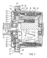
- the approximately pot-shaped housing is 10 slip ringless three-phase generator referred to by a bearing plate 11 - also as a minus heat sink designated - is closed.
- a ball bearing 13 is arranged in a coaxially opposite bulge 15 of the housing Ball bearing 16.
- the shaft 18 is in the two ball bearings a pole wheel 19 with integrated guide piece 19A.
- the shaft 18 has one from the housing 10 or the End shield 11 protruding pin 18A, on the one Pulley 20 is arranged.
- a lamella stand 22 is located approximately in the middle of the housing 10 arranged and coaxial to the shaft 18 with a pole core 23 fixed excitation winding 24.
- the guide piece 19A is with an antimagnetic ring 25 between excitation winding 24 and slat stand 22 firmly connected.
- the so-called Primary and secondary air gaps between the parts mentioned are not designated further, since they are not essential to the invention and otherwise common.
- Figure la shows the circuit structure of the three-phase generator with the winding phases R, S, T of the three-phase stator winding 26 with the winding ends U, V, W and X, Y, Z. These ends are in a delta connection with each other connected and one with the rectifier assembly 27 Bridge rectifier connected.
- the plus rectifier diodes 70 are in the plus heat sink 28 and the minus rectifier diodes 71 in the end shield 11 as Minus heat sink pressed in. Are involved in a known manner the anodes of the plus diodes 70 to a plus connection on Generator led out while the cathodes of the minus diodes 71 as a minus connection directly with the end shield 11 are contacted.
- FIG. 1 shows, the clamping points 44 are over tabs 45 and screws 46 clamped, of which lead wires lead to the circuit board 30.
- Screws 48 to the end shield or the minus heat sink 11 connected in which the not shown MINUS diodes 71 are located in the plus heat sink 28 the PLUS diodes 70.
- Connections 58 to 60 are connected to it for the plus diodes and connections 61 to 63 for the minus diodes attached to the printed circuit board 30 - see FIG. 5.
- There are also four stator connections 65 to 68 recognize that over the tabs 45 with the winding outputs U, V, W, X, Y, Z are contact by screwing them 46 were screwed to the tabs 45.
- Figure 1 is the winding output V, Z can be seen.
- FIG. 6 shows the Lamella stand 22 with its winding 26 shows and one Winding output V, Z as it is at the clamping points 44 is connected. It should also be mentioned that according to FIG the nuts 53 for the screws 46 in the contact ring 34 are injected.
- the lamella stand 22 is spatial with the Ends U, V, W and X, Y, Z of the three-phase stator winding 26 shown. Since the winding strands R, S, T in two halves are wound, the winding ends each consist of two Wires.
Landscapes
- Engineering & Computer Science (AREA)
- Power Engineering (AREA)
- Synchronous Machinery (AREA)
- Motor Or Generator Cooling System (AREA)
- Control Of Eletrric Generators (AREA)
Abstract
Description
Claims (4)
- Elektrische Maschine, insbesondere schleifringloser Drehstrom-Generator der Leitstückläuferbauart, mit einem etwa topfförmigen Gehäuse (10), mit einer Gleichrichterbaueinheit bestehend aus einem Lagerschild (11), einem mit diesem verbundenen Plus-Kühlkörper (28), weiterhin mit einer ebenfalls am Lagerschild (11) angeordneten Leiterplatte (30), welche die Gleichrichterdioden (70, 71) mit den Anschlüssen der Drehstrom-Ständerwicklung (26) verbindet, dadurch gekennzeichnet, daß die Leiterplatte (30) über Anschlüsse (65 bis 68) mit einem Kontaktring (34) verbunden ist, an dem die Wicklungsausgänge (U, V, W, X, Y,Z) der Drehstromwicklung (26) eines Ständers (22) kontaktiert sind, wobei die Drehstromwicklung (26) drei im Dreieckschaltung angeordnete Wicklungsstränge R, S und T hat, die jeweils in zwei Hälften gewickelt sind, wobei der Kontaktring (34) konzentrisch um die Leiterplatte (30) herumführt und vier Anschlußstellen (35 bis 38) aufweist, an welche die Wicklungsausgänge (U bis Z) der Drehstromwicklung (26) derart herangeführt und angschlossen sind, daß an zwei der Anschlußstellen (36, 37) je zwei Enden (U, Y und V, Z) der Wicklungsstränge (R, S, T) zusammengeschaltet sind und an den zwei anderen Anschlußstellen (35, 38) je ein Ende (W, X) von zwei Wicklungssträngen (T und R) angeschlossen ist.
- Maschine nach Anspruch 1, dadurch gekennzeichnet, daß an den Anschlußstellen (35 bis 38) Befestigungsmittel (46) angebracht sind, an welche sich Klemmstellen (44) für die Wicklungsausgänge anlegen.
- Maschine nach Anspruch 1 oder 2, dadurch gekennzeichnet, daß sich an der Leiterplatte (30) Anschlüsse (58 bis 63) für im Pluskühlkörper (28) und im Lagerschild (11) angeordnete Dioden (70, 71) befinden, sowie Anschlüsse (65 bis 68) für den Kontaktring (34).
- Maschine nach Anspruch 2 oder 3, dadurch gekennzeichnet, daß Teile der Befestigungsmittel im Kontaktring (34) eingesetzte Muttern (53) sind, in welche Schrauben (46) für die Anschlüsse (58 bis 63) der Leiterplatte (30) eingeschraubt sind.
Applications Claiming Priority (3)
| Application Number | Priority Date | Filing Date | Title |
|---|---|---|---|
| DE29717416U | 1997-09-30 | ||
| DE29717416U DE29717416U1 (de) | 1997-09-30 | 1997-09-30 | Elektrische Maschine, insbesondere schleifringloser Drehstrom-Generator |
| PCT/DE1998/002911 WO1999017430A2 (de) | 1997-09-30 | 1998-09-30 | Elektrische maschine, insbesondere schleifringloser drehstrom-generator |
Publications (2)
| Publication Number | Publication Date |
|---|---|
| EP1042856A2 EP1042856A2 (de) | 2000-10-11 |
| EP1042856B1 true EP1042856B1 (de) | 2003-02-26 |
Family
ID=8046625
Family Applications (1)
| Application Number | Title | Priority Date | Filing Date |
|---|---|---|---|
| EP98956804A Expired - Lifetime EP1042856B1 (de) | 1997-09-30 | 1998-09-30 | Elektrische maschine, insbesondere schleifringloser drehstrom-generator |
Country Status (4)
| Country | Link |
|---|---|
| EP (1) | EP1042856B1 (de) |
| JP (1) | JP4041283B2 (de) |
| DE (2) | DE29717416U1 (de) |
| WO (1) | WO1999017430A2 (de) |
Families Citing this family (6)
| Publication number | Priority date | Publication date | Assignee | Title |
|---|---|---|---|---|
| US6278206B1 (en) | 2000-06-28 | 2001-08-21 | Visteon Global Technologies, Inc. | Electrical connection apparatus and method for connecting an alternator stator |
| DE10206617A1 (de) * | 2002-02-15 | 2003-08-28 | Cognis Deutschland Gmbh | Wässrige Mittel zur hautfreundlichen Ausrüstung von Vliesstoffen |
| KR100574331B1 (ko) * | 2004-08-31 | 2006-04-27 | 발레오전장시스템스코리아 주식회사 | 스테이터 인출선용 절연부재를 갖는 알터네이터 |
| FR2939574B1 (fr) * | 2008-12-10 | 2016-06-03 | Valeo Equip Electr Moteur | Stator de machine electrique tournante, notamment d'un alternateur. |
| US20110006545A1 (en) * | 2009-07-08 | 2011-01-13 | Hamilton Sundstrand Corporation | Nested exciter and main generator stages for a wound field generator |
| RU2717345C1 (ru) * | 2019-11-19 | 2020-03-23 | федеральное государственное бюджетное образовательное учреждение высшего образования "Башкирский государственный медицинский университет" Министерства здравоохранения Российской Федерации | Способ лечения остеоартрита коленного сустава |
Family Cites Families (4)
| Publication number | Priority date | Publication date | Assignee | Title |
|---|---|---|---|---|
| JPS5872358A (ja) * | 1981-10-23 | 1983-04-30 | Hitachi Ltd | 交流発電機 |
| JPH05161295A (ja) * | 1991-11-29 | 1993-06-25 | Hitachi Ltd | 車両用交流発電機 |
| DE4232929A1 (de) * | 1992-10-01 | 1994-04-07 | Bosch Gmbh Robert | Drehstromgenerator mit Gleichrichter |
| JP3342987B2 (ja) * | 1995-06-28 | 2002-11-11 | 三菱電機株式会社 | 車両用交流発電機 |
-
1997
- 1997-09-30 DE DE29717416U patent/DE29717416U1/de not_active Expired - Lifetime
-
1998
- 1998-09-30 JP JP2000514382A patent/JP4041283B2/ja not_active Expired - Lifetime
- 1998-09-30 EP EP98956804A patent/EP1042856B1/de not_active Expired - Lifetime
- 1998-09-30 DE DE59807344T patent/DE59807344D1/de not_active Expired - Lifetime
- 1998-09-30 WO PCT/DE1998/002911 patent/WO1999017430A2/de not_active Ceased
Also Published As
| Publication number | Publication date |
|---|---|
| EP1042856A2 (de) | 2000-10-11 |
| WO1999017430A2 (de) | 1999-04-08 |
| WO1999017430A3 (de) | 1999-05-20 |
| JP2001518779A (ja) | 2001-10-16 |
| JP4041283B2 (ja) | 2008-01-30 |
| DE59807344D1 (de) | 2003-04-03 |
| DE29717416U1 (de) | 1999-02-04 |
Similar Documents
| Publication | Publication Date | Title |
|---|---|---|
| DE3842588C2 (de) | ||
| DE3211502C2 (de) | Wechselstromgenerator für ein Kraftfahrzeug | |
| EP0513014B1 (de) | Elektrische maschine mit fremdbelüftung | |
| EP0960464B1 (de) | Elektrische maschine, vorzugsweise drehstromgenerator mit gleichrichter-baueinheit | |
| WO2000001055A1 (de) | Elektrische maschine, vorzugsweise drehstromgenerator mit gleichrichter-baueinheit | |
| WO1999049554A1 (de) | Elektromotor, insbesondere mit einem lüfterrad zur bildung eines axial- oder radiallüfters | |
| DE102022207340B3 (de) | Rotoranordnung für eine fremderregte Synchronmaschine | |
| DE29516656U1 (de) | Kollektorloser Elektromotor | |
| DE10063619A1 (de) | Antriebseinheit für Gebläse in Fahrzeugen | |
| EP2089953B1 (de) | Elektrische maschine | |
| DE102018202895A1 (de) | Basiseinheit, Motor und Luftblasvorrichtung | |
| DE102018202893A1 (de) | Basiseinheit, Motor und Luftblasvorrichtung | |
| DE10361859A1 (de) | Elektrische Maschine und dazu vorgesehener Ständer | |
| DE102010064377A1 (de) | Elektrische Maschine | |
| DE2643612A1 (de) | Wechselstromgenerator mit einbau- spannungsregler | |
| EP1042856A2 (de) | Elektrische maschine, insbesondere schleifringloser drehstrom-generator | |
| DE3038444C2 (de) | Ölgekühlter Generator | |
| DE2819824A1 (de) | Synchronmaschine mit gleichrichteranordnung | |
| DE102007034323A1 (de) | Elektrische Maschine | |
| EP2342799B1 (de) | Elektrische maschine mit einem kontaktelement zur elektrischen verbindung elektrischer bauteile | |
| DE3137172C2 (de) | ||
| DE3833574A1 (de) | Elektromotor, insbesondere spaltrohrmotor | |
| EP4243251A1 (de) | Elektronisch kommutierter elektromotor mit flüssigkeitskühlung | |
| EP0087053B2 (de) | Anordnung für eine rotierende Thyristorerregung | |
| DE102008002615A1 (de) | Elektrische Maschine |
Legal Events
| Date | Code | Title | Description |
|---|---|---|---|
| PUAI | Public reference made under article 153(3) epc to a published international application that has entered the european phase |
Free format text: ORIGINAL CODE: 0009012 |
|
| 17P | Request for examination filed |
Effective date: 20000502 |
|
| AK | Designated contracting states |
Kind code of ref document: A2 Designated state(s): DE FR GB IT |
|
| GRAG | Despatch of communication of intention to grant |
Free format text: ORIGINAL CODE: EPIDOS AGRA |
|
| 17Q | First examination report despatched |
Effective date: 20020411 |
|
| GRAG | Despatch of communication of intention to grant |
Free format text: ORIGINAL CODE: EPIDOS AGRA |
|
| GRAH | Despatch of communication of intention to grant a patent |
Free format text: ORIGINAL CODE: EPIDOS IGRA |
|
| GRAH | Despatch of communication of intention to grant a patent |
Free format text: ORIGINAL CODE: EPIDOS IGRA |
|
| GRAA | (expected) grant |
Free format text: ORIGINAL CODE: 0009210 |
|
| AK | Designated contracting states |
Designated state(s): DE FR GB IT |
|
| REG | Reference to a national code |
Ref country code: GB Ref legal event code: FG4D Free format text: NOT ENGLISH |
|
| REF | Corresponds to: |
Ref document number: 59807344 Country of ref document: DE Date of ref document: 20030403 Kind code of ref document: P |
|
| GBT | Gb: translation of ep patent filed (gb section 77(6)(a)/1977) | ||
| ET | Fr: translation filed | ||
| PLBE | No opposition filed within time limit |
Free format text: ORIGINAL CODE: 0009261 |
|
| STAA | Information on the status of an ep patent application or granted ep patent |
Free format text: STATUS: NO OPPOSITION FILED WITHIN TIME LIMIT |
|
| 26N | No opposition filed |
Effective date: 20031127 |
|
| REG | Reference to a national code |
Ref country code: FR Ref legal event code: PLFP Year of fee payment: 19 |
|
| REG | Reference to a national code |
Ref country code: FR Ref legal event code: PLFP Year of fee payment: 20 |
|
| PGFP | Annual fee paid to national office [announced via postgrant information from national office to epo] |
Ref country code: GB Payment date: 20170925 Year of fee payment: 20 Ref country code: FR Payment date: 20170925 Year of fee payment: 20 Ref country code: IT Payment date: 20170926 Year of fee payment: 20 |
|
| REG | Reference to a national code |
Ref country code: DE Ref legal event code: R081 Ref document number: 59807344 Country of ref document: DE Owner name: SEG AUTOMOTIVE GERMANY GMBH, DE Free format text: FORMER OWNER: ROBERT BOSCH GMBH, 70469 STUTTGART, DE |
|
| PGFP | Annual fee paid to national office [announced via postgrant information from national office to epo] |
Ref country code: DE Payment date: 20171013 Year of fee payment: 20 |
|
| REG | Reference to a national code |
Ref country code: FR Ref legal event code: TP Owner name: SEG AUTOMOTIVE GERMANY GMBH, DE Effective date: 20180315 |
|
| REG | Reference to a national code |
Ref country code: DE Ref legal event code: R071 Ref document number: 59807344 Country of ref document: DE |
|
| REG | Reference to a national code |
Ref country code: GB Ref legal event code: PE20 Expiry date: 20180929 Ref country code: GB Ref legal event code: 732E Free format text: REGISTERED BETWEEN 20180927 AND 20181005 |
|
| PG25 | Lapsed in a contracting state [announced via postgrant information from national office to epo] |
Ref country code: GB Free format text: LAPSE BECAUSE OF EXPIRATION OF PROTECTION Effective date: 20180929 |