EP1042028B1 - Monitoring and control for a laryngeal mask airway device - Google Patents
Monitoring and control for a laryngeal mask airway device Download PDFInfo
- Publication number
- EP1042028B1 EP1042028B1 EP98962576A EP98962576A EP1042028B1 EP 1042028 B1 EP1042028 B1 EP 1042028B1 EP 98962576 A EP98962576 A EP 98962576A EP 98962576 A EP98962576 A EP 98962576A EP 1042028 B1 EP1042028 B1 EP 1042028B1
- Authority
- EP
- European Patent Office
- Prior art keywords
- piston
- air
- cylinder
- pressure
- valve
- Prior art date
- Legal status (The legal status is an assumption and is not a legal conclusion. Google has not performed a legal analysis and makes no representation as to the accuracy of the status listed.)
- Expired - Lifetime
Links
- 238000012544 monitoring process Methods 0.000 title claims description 32
- 239000003570 air Substances 0.000 claims description 58
- 238000006073 displacement reaction Methods 0.000 claims description 35
- 238000001356 surgical procedure Methods 0.000 claims description 18
- 230000004044 response Effects 0.000 claims description 16
- 230000001105 regulatory effect Effects 0.000 claims description 12
- 230000002441 reversible effect Effects 0.000 claims description 10
- 230000033228 biological regulation Effects 0.000 claims description 9
- 210000003800 pharynx Anatomy 0.000 claims description 8
- 239000012080 ambient air Substances 0.000 claims description 6
- 238000010926 purge Methods 0.000 claims description 6
- 230000035945 sensitivity Effects 0.000 claims description 5
- 238000004891 communication Methods 0.000 claims description 4
- 210000004072 lung Anatomy 0.000 claims description 4
- 208000003443 Unconsciousness Diseases 0.000 claims description 3
- 230000001419 dependent effect Effects 0.000 claims description 3
- 230000001939 inductive effect Effects 0.000 claims description 3
- 238000012423 maintenance Methods 0.000 claims description 3
- 238000013459 approach Methods 0.000 claims description 2
- 230000006698 induction Effects 0.000 claims 2
- 238000007789 sealing Methods 0.000 claims 1
- 206010002091 Anaesthesia Diseases 0.000 description 23
- 238000001949 anaesthesia Methods 0.000 description 23
- 230000037005 anaesthesia Effects 0.000 description 20
- 238000000034 method Methods 0.000 description 20
- 210000003205 muscle Anatomy 0.000 description 16
- 229910001868 water Inorganic materials 0.000 description 16
- 230000006870 function Effects 0.000 description 15
- 230000000694 effects Effects 0.000 description 14
- 230000036407 pain Effects 0.000 description 12
- 230000003444 anaesthetic effect Effects 0.000 description 11
- 210000003026 hypopharynx Anatomy 0.000 description 8
- 238000004458 analytical method Methods 0.000 description 7
- 230000002232 neuromuscular Effects 0.000 description 7
- 239000003158 myorelaxant agent Substances 0.000 description 6
- 238000005070 sampling Methods 0.000 description 6
- 230000009471 action Effects 0.000 description 5
- 230000008901 benefit Effects 0.000 description 5
- 230000001965 increasing effect Effects 0.000 description 5
- 230000008569 process Effects 0.000 description 5
- 230000001960 triggered effect Effects 0.000 description 5
- 230000000007 visual effect Effects 0.000 description 5
- 238000006243 chemical reaction Methods 0.000 description 4
- 230000006835 compression Effects 0.000 description 4
- 238000007906 compression Methods 0.000 description 4
- 210000000867 larynx Anatomy 0.000 description 4
- OLBCVFGFOZPWHH-UHFFFAOYSA-N propofol Chemical compound CC(C)C1=CC=CC(C(C)C)=C1O OLBCVFGFOZPWHH-UHFFFAOYSA-N 0.000 description 4
- 229960004134 propofol Drugs 0.000 description 4
- 230000000241 respiratory effect Effects 0.000 description 4
- 206010033799 Paralysis Diseases 0.000 description 3
- 230000002547 anomalous effect Effects 0.000 description 3
- 238000004364 calculation method Methods 0.000 description 3
- 238000010276 construction Methods 0.000 description 3
- 230000003247 decreasing effect Effects 0.000 description 3
- 238000001514 detection method Methods 0.000 description 3
- 230000000977 initiatory effect Effects 0.000 description 3
- 239000000463 material Substances 0.000 description 3
- 230000003387 muscular Effects 0.000 description 3
- 230000010355 oscillation Effects 0.000 description 3
- 230000002829 reductive effect Effects 0.000 description 3
- 210000001519 tissue Anatomy 0.000 description 3
- 238000009423 ventilation Methods 0.000 description 3
- GQPLMRYTRLFLPF-UHFFFAOYSA-N Nitrous Oxide Chemical compound [O-][N+]#N GQPLMRYTRLFLPF-UHFFFAOYSA-N 0.000 description 2
- 230000015572 biosynthetic process Effects 0.000 description 2
- 238000009530 blood pressure measurement Methods 0.000 description 2
- 238000004422 calculation algorithm Methods 0.000 description 2
- 230000001276 controlling effect Effects 0.000 description 2
- 238000012937 correction Methods 0.000 description 2
- 230000007423 decrease Effects 0.000 description 2
- 238000013461 design Methods 0.000 description 2
- 238000010586 diagram Methods 0.000 description 2
- 238000011156 evaluation Methods 0.000 description 2
- 230000005284 excitation Effects 0.000 description 2
- 238000003780 insertion Methods 0.000 description 2
- 230000037431 insertion Effects 0.000 description 2
- 230000010354 integration Effects 0.000 description 2
- 230000000670 limiting effect Effects 0.000 description 2
- 238000004519 manufacturing process Methods 0.000 description 2
- 238000012806 monitoring device Methods 0.000 description 2
- 229920001343 polytetrafluoroethylene Polymers 0.000 description 2
- 239000004810 polytetrafluoroethylene Substances 0.000 description 2
- 230000029058 respiratory gaseous exchange Effects 0.000 description 2
- 230000000717 retained effect Effects 0.000 description 2
- 208000024891 symptom Diseases 0.000 description 2
- 238000012546 transfer Methods 0.000 description 2
- 230000001052 transient effect Effects 0.000 description 2
- 206010049816 Muscle tightness Diseases 0.000 description 1
- 206010039897 Sedation Diseases 0.000 description 1
- 239000004809 Teflon Substances 0.000 description 1
- 229920006362 Teflon® Polymers 0.000 description 1
- 206010043521 Throat irritation Diseases 0.000 description 1
- 230000004308 accommodation Effects 0.000 description 1
- 230000037007 arousal Effects 0.000 description 1
- 230000009286 beneficial effect Effects 0.000 description 1
- 230000036770 blood supply Effects 0.000 description 1
- 230000002490 cerebral effect Effects 0.000 description 1
- 230000008602 contraction Effects 0.000 description 1
- 238000011157 data evaluation Methods 0.000 description 1
- 238000009795 derivation Methods 0.000 description 1
- 238000011161 development Methods 0.000 description 1
- 210000002409 epiglottis Anatomy 0.000 description 1
- 230000002349 favourable effect Effects 0.000 description 1
- 239000002783 friction material Substances 0.000 description 1
- 230000005484 gravity Effects 0.000 description 1
- 238000009434 installation Methods 0.000 description 1
- 230000003993 interaction Effects 0.000 description 1
- 230000002452 interceptive effect Effects 0.000 description 1
- 230000001788 irregular Effects 0.000 description 1
- 238000005259 measurement Methods 0.000 description 1
- 230000007246 mechanism Effects 0.000 description 1
- QSHDDOUJBYECFT-UHFFFAOYSA-N mercury Chemical compound [Hg] QSHDDOUJBYECFT-UHFFFAOYSA-N 0.000 description 1
- 229910052753 mercury Inorganic materials 0.000 description 1
- 239000000203 mixture Substances 0.000 description 1
- 210000004877 mucosa Anatomy 0.000 description 1
- 230000004118 muscle contraction Effects 0.000 description 1
- 229940035363 muscle relaxants Drugs 0.000 description 1
- 230000017074 necrotic cell death Effects 0.000 description 1
- 239000001272 nitrous oxide Substances 0.000 description 1
- 230000003287 optical effect Effects 0.000 description 1
- 230000036961 partial effect Effects 0.000 description 1
- 229920001296 polysiloxane Polymers 0.000 description 1
- 230000002035 prolonged effect Effects 0.000 description 1
- 238000011084 recovery Methods 0.000 description 1
- 230000009467 reduction Effects 0.000 description 1
- 230000011514 reflex Effects 0.000 description 1
- 238000012552 review Methods 0.000 description 1
- 230000036280 sedation Effects 0.000 description 1
- 238000012163 sequencing technique Methods 0.000 description 1
- 239000007787 solid Substances 0.000 description 1
- 230000005236 sound signal Effects 0.000 description 1
- 230000002269 spontaneous effect Effects 0.000 description 1
- 230000009747 swallowing Effects 0.000 description 1
- 238000012360 testing method Methods 0.000 description 1
- 238000012549 training Methods 0.000 description 1
- 238000010200 validation analysis Methods 0.000 description 1
- BGSZAXLLHYERSY-XQIGCQGXSA-N vecuronium Chemical compound N1([C@@H]2[C@@H](OC(C)=O)C[C@@H]3CC[C@H]4[C@@H]5C[C@@H]([C@@H]([C@]5(CC[C@@H]4[C@@]3(C)C2)C)OC(=O)C)[N+]2(C)CCCCC2)CCCCC1 BGSZAXLLHYERSY-XQIGCQGXSA-N 0.000 description 1
- 229960003819 vecuronium Drugs 0.000 description 1
- 238000012795 verification Methods 0.000 description 1
- XLYOFNOQVPJJNP-UHFFFAOYSA-N water Substances O XLYOFNOQVPJJNP-UHFFFAOYSA-N 0.000 description 1
Images


Classifications
-
- A—HUMAN NECESSITIES
- A61—MEDICAL OR VETERINARY SCIENCE; HYGIENE
- A61M—DEVICES FOR INTRODUCING MEDIA INTO, OR ONTO, THE BODY; DEVICES FOR TRANSDUCING BODY MEDIA OR FOR TAKING MEDIA FROM THE BODY; DEVICES FOR PRODUCING OR ENDING SLEEP OR STUPOR
- A61M16/00—Devices for influencing the respiratory system of patients by gas treatment, e.g. ventilators; Tracheal tubes
- A61M16/04—Tracheal tubes
- A61M16/0434—Cuffs
- A61M16/044—External cuff pressure control or supply, e.g. synchronisation with respiration
-
- A—HUMAN NECESSITIES
- A61—MEDICAL OR VETERINARY SCIENCE; HYGIENE
- A61M—DEVICES FOR INTRODUCING MEDIA INTO, OR ONTO, THE BODY; DEVICES FOR TRANSDUCING BODY MEDIA OR FOR TAKING MEDIA FROM THE BODY; DEVICES FOR PRODUCING OR ENDING SLEEP OR STUPOR
- A61M16/00—Devices for influencing the respiratory system of patients by gas treatment, e.g. ventilators; Tracheal tubes
- A61M16/04—Tracheal tubes
- A61M16/0402—Special features for tracheal tubes not otherwise provided for
- A61M16/0409—Special features for tracheal tubes not otherwise provided for with mean for closing the oesophagus
-
- A—HUMAN NECESSITIES
- A61—MEDICAL OR VETERINARY SCIENCE; HYGIENE
- A61M—DEVICES FOR INTRODUCING MEDIA INTO, OR ONTO, THE BODY; DEVICES FOR TRANSDUCING BODY MEDIA OR FOR TAKING MEDIA FROM THE BODY; DEVICES FOR PRODUCING OR ENDING SLEEP OR STUPOR
- A61M16/00—Devices for influencing the respiratory system of patients by gas treatment, e.g. ventilators; Tracheal tubes
- A61M16/04—Tracheal tubes
- A61M16/0434—Cuffs
- A61M16/0443—Special cuff-wall materials
-
- A—HUMAN NECESSITIES
- A61—MEDICAL OR VETERINARY SCIENCE; HYGIENE
- A61M—DEVICES FOR INTRODUCING MEDIA INTO, OR ONTO, THE BODY; DEVICES FOR TRANSDUCING BODY MEDIA OR FOR TAKING MEDIA FROM THE BODY; DEVICES FOR PRODUCING OR ENDING SLEEP OR STUPOR
- A61M25/00—Catheters; Hollow probes
- A61M25/10—Balloon catheters
- A61M25/1018—Balloon inflating or inflation-control devices
- A61M2025/1022—Balloon inflating or inflation-control devices driven by a rotary motor-activated pump
Definitions
- This invention relates to apparatus useful for controlling and/or monitoring the inflation pressure within a laryngeal mask airway (LMA) device and to a means for monitoring a patient's welfare by way of fluctuations in that inflation pressure.
- LMA laryngeal mask airway
- LMA devices are now well known and are in widespread use in patient care, both during and after surgical procedures and during procedures that involve maintaining a clear airway. Such devices and their construction and use are described in various patent publications, for example, British Patent No. 2,205,499 and United States Patent Nos. 4,509,514; 5,303,697; 5,241,956; and 5,282,464.
- LMA devices are well accepted tools in patient care is borne out by simple statistics. For example, it is estimated that such devices are used in approximately 50 percent of all operative procedures requiring the use of general anaesthetic in the UK, and their use is becoming increasingly accepted elsewhere in Europe and in the USA.
- an LMA device comprises an airway tube that is sized and curved for general conformance with a patient's airway; the airway tube extends from a proximal end that is external to the patient, to a distal end that carries mask structure in the form of a bowl or backing plate which faces and covers the patient's laryngeal inlet and which is continuously surrounded by a flexible ring or cuff that is selectively inflatable for resiliently sealed conformance to body structure around the laryngeal inlet.
- the LMA is first fully deflated to aid its insertion and is then passed through the patient's mouth and throat into its correct position, with the mask over the laryngeal opening.
- the inflatable cuff surrounding the mask structure is then inflated to form a seal between the mask and the laryngeal opening.
- the air pressure with which the cuff is inflated forces the rear of the bowl of the mask against firm tissues at the back of the throat to maintain the device in place and to retain the seal. In this way, the device forms an open airway through which the patient's lungs can be ventilated.
- Such LMA devices have proved to be both sturdy in construction and relatively straightforward to use, even by paramedics after the necessary training; however, if a mask is wrongly inserted, a reliable airway is not in fact formed and the patient's lungs are not then properly ventilated.
- the soft compliant silicone material of the cuff has been known to absorb nitrous oxide from anaesthetic gas mixture thereby increasing the pressure within the cuff, and the cuff itself may occasionally develop leakage causing its internal pressure to decrease. Also, it has been found that too high an inflation pressure will cause the cuff to restrict the blood supply to the mucosa overlying the muscles around the laryngeal inlet, and prolonged use of an LMA device in such circumstances can lead to tissue necrosis.
- muscle tension (tone) in the lower throat bears a relationship to the patient's apparent response to painful stimuli; thus, it is possible to gain information on the patient's anaesthetic depth by monitoring muscle tone in the hypopharynx.
- very small changes in that muscle tone are reflected through the LMA cuff and are further reflected through the shared air volume and that such pressure feedback readings can be utilized to both automatically adjust the inflation pressure of the LMA cuff and also to detect changes in the muscle tone in the hypopharynx.
- the detection of such changes is most preferably made without causing patient duress, and to such end it has been observed that it is most beneficial to inflate the cuff to pressures not much higher than 60 - cm H20; for example, 50 - cm H20, and generally in the range 25 - cm H20 to 100 - cm H20.
- the acceptability of utilizing pressures above 60 - cm H20 has been observed to cause patient throat irritation, especially in procedures of longer duration, and may risk damage to such tissue.
- US 4 872 483 discloses monitoring an inflatable cuff of a device in a patient, however there is no disclosure or suggestion of a device as set out in the characterising clause of Claim 1 herein below.
- the present invention has as its overall object to provide apparatus which is capable (a) of monitoring with fine sensitivity, for example 0.0625cm H20, the pressure within the cuff of an LMA device that has been properly installed within a patient's airway; and (b) of maintaining a preset inflation pressure within narrow tolerances, for example + 0.5 - cm H20.
- the pressure unit cm-water is used which is equal to 98 Pa slightly dependent on gravity.
- the monitoring of LMA inflation pressure in the course of the surgery can include such automated analysis of LMA inflation pressure variation as to warn the operator that the patient has just exhibited an anomaly indicative of an incipient stage of awakening, thereby alerting the anaesthetist or anaesthesiologist (which are terms hereinafter used interchangeably) that the patient is in immediate need of further anaesthetic.
- a further object is to provide apparatus which meets the foregoing objects, is relatively inexpensive to manufacture, is straightforward to set-up, and is reliable to operate and maintain.
- a still further object is to achieve the foregoing pressure regulation without resort to utilization of some other form of system whose components would introduce an additional time constant or hysteresis effect on pressure monitoring functionality; such as would be caused by an accumulator-type system that is reliant upon a pumped or otherwise elevated pressure reservoir to replenish device operating pressure.
- Apparatus according to the invention can be used for maintaining a predetermined pressure in an LMA device and for monitoring pressure changes within the LMA device to detect changes in the patient's condition and to control the administration of anaesthetic and/or muscle relaxant.
- apparatus for monitoring the level of unconsciousness of a patient in the course of a surgical procedure on the patient, wherein the patient has an installed inflatable device having wall contact with at least a portion of the patient's pharynx characterised in that said apparatus comprises:
- the reversibly operable drive means comprises an electrical motor coupled for reversible drive of a lead-screw and nut means threaded to the lead screw, the nut means being longitudinally guided and keyed against rotation and connected for direct longitudinal displacement of the piston in the cylinder.
- the preferred electric motor is a stepper motor driven in the open loop mode and which operates without slip or hysteresis lag/error.
- the direction and speed of the motor rotation are dependent upon the sequence and frequency of the phase of applied excitation.
- the reversibly operable drive means comprises such a stepping motor, in which the pressure-responsive means produces a first digital-signal output, in which the set-point value is in the form of a second digital-signal output, and in which the comparator means includes a microprocessor programmed to supply digital-control signals for operation of the motor.
- a first normally closed solenoid valve is connected to the outlet connection of the syringe means for interposition between the outlet connection and the inflatable means, the solenoid of the valve having electrical connection to the control means whereby to actuate the valve to open condition for at least the time duration of the electrical-output signal and as long as the electrical-output signal is other than zero.
- a second normally closed solenoid valve is connected to the outlet connection of the syringe means; when actuated to open condition, this second valve provides syringe access to ambient air, for adding to or dumping system air, while the first solenoid valve is in closed condition.
- the cylinder has a ported but otherwise closed longitudinal end; and each of the two normally closed solenoid valves is connected to serve the ported end of the cylinder.
- the first normally closed solenoid valve is also connected to the inflatable means of the LMA and is actuable to interchange air between the inflatable means and the cylinder pursuant to the direction of displacement of the piston; and the second normally closed solenoid valve is actuable, as described above, to admit ambient air to the cylinder or to expel air from the cylinder, depending upon the direction of displacement of the piston.
- First limit-switch means produces an electrical signal for a sensed condition of piston advance into a predetermined limiting proximity to the closed end
- means including a microprocessor is responsive to the signal of sensed piston proximity, the microprocessor being programmed (i) to foreclose operation of the drive means and to return the first solenoid valve to its normally closed position, then (ii) to actuate the second solenoid valve to open condition while operating the drive means for a predetermined stroke in reverse, thus inducing a fresh charge of ambient air into the cylinder pursuant to the predetermined stroke in reverse, and (iii) deactivating the second solenoid valve and enabling the comparator means to reestablish the set-point value of pressure within the cylinder before reactivating the first solenoid valve and returning the comparator means to its function of regulating LMA-inflation pressure to its set-point value.
- mask-inflation pressure is continuously monitored.
- the instantaneously observed mask-inflation pressure is monitored for possible traverse of predetermined upper and/or lower threshold limits of "normal" regulation; and, upon observed-pressure traverse of one of these limits, a first alarm signal is issued with an audible warning, it being interpreted that, even though still asleep and under sedation, the patient has involuntarily betrayed an indication of hypopharynx/ larynx muscle contraction, with accompanying transient local compression of the patient's inflated LMA.
- Rate-related occurrences are further described below and are determined by continuous review of analyses performed on a gated sequence of several successive readings that are stored within the system; and the output of such analyses is continually displayed at the system monitor.
- This rate-related analysis of observed inflation pressure provides further indication of the patient's incipient and prospective awakening process and provides verification of first alarm, further alerting the anaesthesiologist with visual warning to "check anaesthesia".
- Fig. 1 the monitoring system or device of Fig. 2 is shown at 10 with various control buttons including a system start/stop button 52, a "regulation" start/stop button 53, an alarm-reset button 54, an "ENTER” button 55, and a rotary knob 56 for selection, inter alia , of set-point or threshold.
- a system start/stop button 52 a "regulation” start/stop button 53
- an alarm-reset button 54 an "ENTER” button 55
- a rotary knob 56 for selection, inter alia , of set-point or threshold.
- the monitoring system 10 has an outlet connection to the flexible inflation/deflation air-supply line 11 of an LMA device 12 installed in a patient 13.
- the LMA device 12 is seen to comprise an airway tube 14 with proximal-end means 15 for external accommodation of ventilating or anaesthetizing supply to the patient's lungs via mask structure 16 having a backing plate 17 connected at 18 to the distal end of tube 14, the backing plate being peripherally surrounded by an inflatable/deflatable ring or cuff 19 of resiliently flexible material; cuff 19 is shown in inflated condition, in peripherally sealed relation to body structure surrounding the patient's laryngeal inlet 20, and in distally located relation to the patient's aesophageal inlet 21 (the hypopharynx).
- Internal structure of the mask will be understood to include known means (not shown) to prevent the patient's epiglottis 22 from interfering with air or anaesthetizing flow through the mask, in either direction, between tube 14 and the patient's laryngeal inlet 20.
- the inflatable/deflatable ring or cuff 19 of an LMA device is operated manually by a hand-held syringe (not shown) that is detachably connected to check-valve means 11A forming an outer end of line 11 of the LMA; when the syringe is detached, the check-valve means 11A is operative to retain the currently inflated or deflated state of the LMA.
- the anaesthetist will know roughly to what pressure the cuff can safely be inflated once the LMA has been properly installed in the patient.
- the control system can be utilized to inflate the cuff after it is installed in the patient, especially with the smaller cuff sizes, the above described manual procedure of inflation is recommended prior to connecting the LMA inflation/deflation line 11 to the control system of Fig. 2.
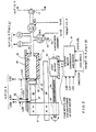
- an air-control port 11' will be understood to include suitable means for detachable connection to the inflation/deflation air line 11 of Fig. 1; and an elongate flexible connection or extension line 11B has (i) a system-connector end (not shown) that is detachably connected to control port 11', and (ii) an LMA-connector end that is compatibly connected to so coact with the connector end of the check-valve means 11A as to maintain lines 11/11B as a continuously open passage of system communication with inflatable means 19 of the LMA.
- Air-displacement means comprises syringe means in the form of a solid body 25 of low-friction material such as PTFE (Teflon) with a cylindrical bore 26 having an open (or tail) end for coaction with piston means 27.
- Body 25 is fixed to a frame member 28 and extends longitudinally to a closed (or head) end having a port connection 29 to a direct line to the LMA inflation/deflation connection means 11'; in this direct line, a first normally closed solenoid valve V1 must be actuated to open condition if inflation air is to pass in either direction between cylinder 26 and the inflatable/deflatable means 19 of the LMA.
- Piston 27 is rigidly mounted to or formed with the head end of a longitudinal rod 30, the tail end of which is clamped to a slide block 31.
- Block 31 establishes a rigid lateral-offset arm for longitudinally stabilized guidance at 32 and for reversibly driven longitudinal displacement by frame- based electrical stepper motor means 33 and its lead-screw output shaft 34;
- shaft 34 has threaded engagement to a nut-like bore 34' in the rigid lateral-offset arm of slide block 31, and preferably the threaded bore 34' is formed in a body of PTFE that is secured to slide block 31.
- the guide means 32 will be understood to be a schematic designation for a commercial longitudinal "linear-bearing" assembly (widely known and available under the name or mark "ROLLON") wherein an elongate first raceway element is fixed to a frame member, wherein an elongate second raceway element is fixed to the slide block 31, and wherein antifriction elements, such as bearing balls, ride and space the raceways of the respective raceway elements.
- ROLLON commercial longitudinal "linear-bearing” assembly
- Motor means 33 is of a stepping variety wherein a precise directional control via variance of the relative excitation of each of four input terminals of the motor.
- the amount of shaft 34 rotation (and thus of piston 27 displacement) is controlled by motor controller and driver means 47, as shown in Fig. 2.
- Fig. 2 indicate an overall length L of piston 27 travel in bore 26, for purposes of delivering inflation air from bore 26 to the inflatable/deflatable ring or cuff 19 of the LMA, as long as solenoid valve V1 remains actuated to open condition; this same length can also be available for a retraction stroke of piston 27, wherein a controlled quantity of inflation air may be extracted from cuff 19.
- Fixedly mounted limit switches LS1 and LS2 are schematically indicated by arrow marks in Fig. 2, to suggest a stop and/or reversing device at each of the longitudinal limits of the overall length L of piston travel. However, as shown in Fig.
- piston 27 is at offset ⁇ L outside of the cylindrical bore, wherein the arrow designated LSO identifies the point at which a coacting lug or other switch-actuating device 37 carried by piston rod 30 coacts with limit switch LSO to electrically or otherwise signal achievement of the piston-retracted position shown, with concomitant termination of drive pulses from driver circuit in Fig. 3; suitably and preferably, each of the limit switches is an optical device, relying on the lug or other actuating device 37 to be opaque and therefore able to cut or interrupt a light beam, from a source to a photocell, at each of the respective locations at which limit switch action is to occur.
- the head end of piston rod 30 has a radial flange formation 38, circumferentially shrouded by a resilient cap 39, having an undercut bore which readily snaps into resiliently retained engagement to the flange formation 38, as when servicing the apparatus by replacing a used cap 39 with a new cap 39.
- Some pressure-regulating operations can have the effect of causing interference with the sensing of pressure changes reflecting patient muscle reflex.
- the system of the invention has been designed to minimize such interference through its design concept as an essentially closed-volume system, wherein adjustments for cuff 19 pressure deviation are made by increments of displacement within a shared volume of air, as between (i) the volume ahead of the piston 26 and within the head end of the cylinder and (ii) the volume in the cuff 19.
- This is superior to systems that regulate pressure by using an accumulator or reservoir of elevated pressure to compensate for cuff pressure changes either by introducing air from such an accumulator or by voiding air to atmosphere.
- first P1 and second P2 pressure-monitoring transducers which indicate the overall pressure in the device, are connected to redundantly monitor air pressure in the line between cylinder-outlet port 29 and the normally closed first solenoid valve V1.
- a second normally closed solenoid valve V2 is shown connected to the air line between cylinder port 29 and the first solenoid valve V1.
- valve V2 When actuated to open condition, valve V2 establishes a path from its open-air end 44 to the air line from cylinder port 29 to the first solenoid valve, so that, with valve V1 in its closed unactuated condition and with valve V2 actuated to its open condition, a right-to-left displacement of piston 27 in cylindrical bore 26 will induce an inflow of fresh (ambient) air into the described system.
- a left-to-right displacement of piston 27 in bore 26 will discharge excess air or gas from the system.
- valve V2 in its normally closed condition and with valve V1 actuated to its open condition, a right-to-left displacement of piston 27 will draw inflation air from (and thus deflate) means 19 of the LMA. And for the same conditions of valve V2 unactuated and of valve V1 actuated, a left-to-right displacement of piston 27 will supply inflation air to means 19 of the LMA.
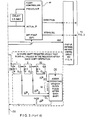
- Control signals necessary for actuation of valves V1 and V2 are provided by separate outputs that are derived from basic program-sequencing signals from a separate microprocessor means of a controller 60 for start-up, centering, and reset.
- the control circuit of Fig. 3 is bypassed and the inputs to stepper motor controller and driver 47 are controlled by the controller 60 for start-up, centering, and reset.
- the bypass of the Fig. 3 control circuit is accomplished by the operation of two single-pole, two-position switches 42. Such operation of switches 42 will occur when the unit is first powered up, at which point a start-up sequence is initiated.
- the operation of stepper motor 33 is controlled during start-up sequence by controller (60) for start-up, centering, and reset.
- the displacement-volumetric capacity of the syringe bore 26 is substantially 20 cc, between LS1 and LS2 operations at the respective extremes of piston displacement L in bore 26; for a bore 26 diameter of 24 mm, the displacement-volumetric capacity of 20 cc is realized by a full-stroke displacement L of about 45 mm, which can be taken as the illustratively useful displacement range of the system.
- the useful range L of piston 27 displacement involves 36,000 discretely pulsed step increments; for initial set-up purposes, a recommended "fast" repetition rate of pulsed steps at 5,000 Hz is to be applied to produce a piston-displacement speed of 6.25 mm/sec. For normal pressure-regulating displacements, a recommended "slow" repetition rate of pulsed steps at 500 Hz is to be applied to produce a piston-displacement speed of 0.625 mm/sec.
- any automatic pressure-regulating correction is preferably achieved by an increment of piston displacement, wherein the increment begins from the mid-point of the useful range L, so that the indicated regulating range of motor displacement is normally accomplished within the scope of 18,000 pulses to motor 33, thus enabling a volume displacement of at least 10 cc, in the LMA-inflating direction or in the LMA-deflating direction, as needed.
- this range limitation is found to serve any of the above-noted LMA sizes, even though the range of inflation volumes is about 10:1.
- the preferred method of initially inflating LMA ring 19 is for the anaesthetist to use syringe means. Whether or not the LMA inflation ring 19 is inflated manually, the system of Figs. 1, 2 and 3 is adapted to quickly assume pressure-monitoring control of inflation ring 19 to the predetermined set point, which will be understood to present a desired pressure set-point value SP (e.g., 50-cm H2O) as part of the display 49.
- SP pressure set-point value
- the LMA control system 10 is capable of performing the initial task of cuff inflation, such initial inflation by the system 10 may be practical only for cuffs of smaller volume capacity and is not presently preferred.
- valve V2 for start-up, centering, and reset
- Pulses are then sent at high speed (5,000 Hz) via stepper motor controller and driver 47, operating motor 33 to displace at high speed piston 27 from its retracted position, which is determined by lug 37 coaction with limit switch LSO.
- Piston 27 rapidly traverses the full range (L) of piston 27 travel in bore 26 in left-to-right motion.
- lug 37 will actuate limit switch LS1, thereby initiating in the stepper motor controller and driver 47 a count of number of pulses that are required to drive the piston as a function of displacement L. The count is terminated only when lug 37 actuates limit switch LS2, at which point the full count is entered into memory of controller 60, and an automatic divide-by-two operation is effected, with its half-count value entered into memory of the controller 60 and also entered into memory of the stepper motor controller and driver 47. Thereafter the stepper motor controller and driver 47 will track each subsequent command that operates motor 33 to independently maintain an awareness of piston 27 position.
- a signal is then sent by the controller 60 for travel to start in the opposite direction at the same high rate of speed until a pulse count is reached indicative that piston 27 has reached its mid-position (or "L/2 "). Valve V2 is then deactivated, returning it to its normally-closed condition.
- Both switches 42 in Fig. 4 then simultaneously transfer from the first ("1") position to the second ("2") position, thereby allowing a fuzzy-logic controller 46, shown in Fig. 3, to assume control of motor 33.
- the fuzzy-logic controller 46 will operate in accordance with logic rules set forth below in Table 1, providing the signal necessary for piston 27 to continue its travel in the left-to-right direction until pressure generated at the head end of the cylinder 26 equals a preprogrammed check-point pressure, typically 20-cm H2O; and once such value has been attained, for reasons explained in the following section, piston 27 will be further actuated to continue its travel until the set-point value SP has been attained.
- the controller 60 will then actuate valve V1, transferring V1 to open condition.
- controller 60 for start-up, centering, and reset
- steps e.g., the preprogrammed check-point pressure to be attained prior to travel of the number of steps required for piston 27 to traverse one-eighth (1/8) of displacement L
- an audible and visual alarm will issue and the system will prohibit automatic system operation.
- a failsafe mode may be triggered during the course of regular system operation upon substantial deviation between the redundant pressure sensors.
- the pressure is redundantly sensed by pressure transducers P1 and P2, from which independently sensed pressure readings are continuously compared by a comparator means "A" 40.
- a hardware-error HW alarm will be generated when a difference other than substantially zero is detected between P1 and P2. This hardware-error alarm is issued in the form an audible and visual indication, alerting the anaesthesiologist to assume manual inflation control of the LMA. Then, a short period of time after issuing such hardware-error alarm, comparator means "A" 40 will go to failsafe mode, closing V1 and V2 in order to maintain the pressure within the LMA cuff.
- Fuzzy-controller operation is described by the logic rules set forth below in Table 1.
- the first two columns in Table 1 reflect the previous pressure and the current pressure, each as compared to SP.
- the delay time between the first and second columns is one-half (1 ⁇ 2) second.
- the last column in Table 1 reflects the command that will typically be sent by the fuzzy-logic controller 46 to motor controller 47. Because during normal operation the stepper motor 33 operates only at slow speed, the fuzzy command is sent in terms of direction and number (N) of steps.
- the described pressure-regulating process that is conducted by the fuzzy-logic controller preferably performs its task within a range of operation defined by a deadband of 0.5-cm H2O on each side of the set-point SP.
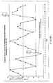
- Fig. 5 illustrates a respiratory waveform which the system of the invention has used both to regulate pressure of the LMA cuff 19 and to monitor the LMA-inflation pressure.
- the patient in this example is under surgery and is being mechanically ventilated, i.e., the patient's ventilation is the result of positive pressure being exerted through airway tube 14, also referred to as intermittent positive-pressure ventilation, or "IPPV".
- Fig. 5 depicts the ability of the device of the invention to monitor oscillations (fluctuations) about the set-point SP (50-cm H2O in this example), wherein such oscillations occur at a rate of approximately twelve cycles per minute, which is typical of the respiratory cycle of a "normal" anaesthetized adult patient.
- Fig. 5A provides an example of the patient experiencing a pain stimulus, which the system of the invention will detect and report via alarm procedures that are the subject of discussion below.
- the graph of Fig. 5A is illustrative of competing forces at play, once disturbed by reaction to a pain stimulus of the character indicated.
- the system of the invention will have been in its normal "regulating" mode, doing what it can, based on its repeated sampling (at 0.5-second intervals) of measured pressure (e.g ., P1 ) in relation to the set point SP and using this reading to determine and make the proper displacement of piston 27.
- the pattern of neuromuscular-derived pressure variations which follow a pain stimulus, and piston displacements that will be called for and may not be within the capacity of described mechanism to track, can therefore create a disturbed pattern of measured pressures while the regulating mode is attempting to reestablish itself.
- the normal regulating mode and the patient's neuromuscular system will be attempting to adapt to changed and changing conditions, as may result from the patient's neuromuscular response to a deepening ("rescuing") further dose of anaesthesia.
- Figs. 3, 5, and 5A, and the charts and tables Fig. 6A, 6B, 6C, and 6D, serve for illustration of two automatic techniques whereby the device of Figs. 1, 2, and 3 can alert the anaesthetist that, during the course of a surgical operation on an anaesthetized patient, the patient has given an early neuromuscular indication of a pain stimulus which the patient's current anaesthetized level has been unable to block, even though the patient is still sufficiently sedated to be unconscious or otherwise unaware of the pain stimulus.
- Such neuromuscular indication demonstrates to the attending anaesthetist that the patient is contracting muscles of his larynx and hypopharynx--a phenomenon indicative of an incipient stage of the patient's awakening process--with potentially serious consequences if the surgical procedure has not yet been completed.
- the inflated ring or cuff 19 of the installed LMA is thus the means of early detection of a localized neuromuscular response, which is deducible from a sudden reaction of the regulating function of the described system, as the same is seen to occur in the disturbed and irregular pattern of pressure excursions in Fig. 5A, wherein bracketing and legend identify a period of pain stimulus due to an event occurring during a surgical procedure.
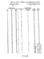
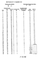
- Fig. 7 displays empirical values of the varying pressure fluctuations that were observed to occur as the anaesthetist intentionally allowed the patient to partially revive from the depths of anaesthesia, it being understood that a chart similar to Fig. 7 was available in real time on display 49 during the course of the surgical procedure. The pressure changes are displayed on the ordinate in cm H2O, with the set-point SP having been selected at 60-cm H2O. Fig. 7 displays events that transpired toward the conclusion of a surgical procedure in which the patient, "Patient 5", was anaesthetized with a continuous feed of propofol, a common and popular anaesthetic.
- Fig. 7 Three specific time periods are recognizable in Fig. 7, and each of these intervals corresponds to the initiation of a variance in the amount of anaesthetic administered to Patient 5.
- the continuous administration of propofol was stopped.
- a significant increase in activity of muscles in the larynx/pharynx area is readily observable in the region contacted by the LMA cuff 19.
- the third period in Fig. 7 starts at approximate time 73-minutes, and identifies when the administration of propofol was again stopped, and the patient was allowed to fully awaken. Note that there are no further readings after approximate time 82- minutes, because the LMA was at that time removed from the patient's laryngeal area.
- Fig. 7 The events displayed in Fig. 7 provide clear evidence that the monitoring system of the invention functions at a level of sensitivity permitting detection of muscular activity indicative of the awakening sequence.
- E1 and E2 are the values automatically compared to each pressure signal fluctuation for determination of the anaesthesia-level alarms, A1 and A2.
- the attending anaesthetist is able to individually select, i.e., to vary E1 and E2 via monitoring device 10.
- A1 is an instantaneous-type alarm, triggered whenever the respiration waveform deviates above or below the "check anaesthesia" alarm window that is framed by E1 and E2.
- the initial warning alarm A1 is triggered by any single deviation from the "check anaesthesia" alarm window.
- the A1 alarm will be presented to the anaesthesiologist in audible form. Once thus warned, the anaesthetist is alerted to make an immediate corrective response, as by increasing the strength of the anaesthetic being administered to the patient.
- Alarm A2 is a rate-related alarm that is determined (i) by a window-related value ET (explained below) and (ii) a calculated mean (Y) based on successive samples of the detected waveform of varying LMA-inflation pressure, wherein the samples are taken for each successive 0.1-second sampling interval, and are effectively integrated and stored as absolute values in a word-summing array circuit, as shown in Fig. 3; each of the absolute values is taken for its sampled magnitude with reference to a steady base line, conveniently the set-point value, as shown in Figs. 6A and 6B. If the mean value, i.e., the sum of the most recent successive thirty-two integrated samples, divided by 32 (61, Fig.
- ET window-related value
- the A2 alarm will issue, such as "CHECK ANAESTHESIA", to the anaesthetist by a combination of visual and/or audio signals.
- the anaesthetist is thereby further alerted to make an immediate corrective response, as by increasing the strength of the anaesthetic which is being administered to the patient.
- ] , wherein k is a selected value in the range 3 to 6 (and preferably 4), it being explained that with k 4, the "divide-by-4" relationship establishes a preferred practical safety factor by means of which the "CHECK ANAESTHESIA" alarm is reliably issued even though the instantaneous-type alarm A1 may not have issued.
- Fig. 5A which is illustrative of a pain-stimulus event observed in a surgical procedure, will be seen to give rise to determinations which are major departures from the normal situation depicted in Fig. 5.
- the first alarm A1 will be triggered, and the second alarm A2 may not immediately be triggered.
- the integration and mean-value development described above can result in a "CHECK-ANAESTHESIA" alarm A2, even if a threshold-traverse needed for the first alarm A1 may not have occurred.
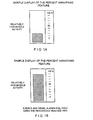
- the anaesthesiologist may monitor continued progression in the form of percent awakening that can be displayed as shown in Fig. 1B, the same being discussed below under the heading, "Display Feature".
- the display 49 contains a window of time through which the continuously varying signal, such as that shown in Figs. 5, 5A, 6B, 6D, and 7, will show the latest single full minute of regulated pressure variations, passing into the window at its left-hand margin, and passing out of window viewability at the right-hand margin.
- FIG. 1A and Fig. 1B An additional method for displaying the results of the above-described integration/summation process (mean value) is shown in Fig. 1A and Fig. 1B, where these two displays in the course of time indicate a progression, from a deeper level of anaesthesia, shown in the first example Fig. 1A, to an incipient level approaching awakening, shown in the second example Fig. 1B.
- the display preferably consists of a bar chart that shows, as on a percent scale, the output of the successively integrated function described above.
- the initial value of this continually-updated display is established for each individual patient, preferably after the anaesthetized patient is positioned by the surgeon on the operating table, in readiness for surgery.
- the parameter equivalent to a 100% display reading will equate to the full value of ET, at which point the "CHECK ANAESTHESIA" alarm will issue.
- Also provided for utilization by anaesthetist and/or other personnel studying a particular surgical procedure is the ability to connect separate microprocessor or other data-presentation means to a computer interface 41, thus providing for the monitoring, recording and analysis of system indicators on separate electronic media, as when more sophisticated recording and analyses are desired.
- both the upper and the lower peak amplitudes from at least eight consecutive waveforms are sampled, averaged, and mean values for the upper and lower peaks are determined.
- Two checks for validation of peak values are used; all eight upper and lower limits that are sampled must be obtained during the same two-minute sampling period, and small oscillations that may otherwise be identified as peaks can be eliminated by operator input of a preset minimum amplitude.
- the preferred device will allow the autoscaling feature only to reduce, and not to automatically enlarge, the check anaesthesia alarm window.
- the amount by which autoscaling can vary E1 and E2 is fully adjustable between zero and one hundred percent, with a default value of fifty percent. It is interesting to note that such autoscaling frequently causes E1 and E2 to no longer be symmetrical about set-point SP, similar to the alarm window shown in Fig. 6B.
- the system of the invention will automatically compensate for leaks and gains in monitored inflation air. Because the stepper motor controller and driver 47 maintain a count of direction commands issued to the stepper motor 33, the stepper motor driver 47 is able to and will so indicate when piston 27 has reached an end of its travel. Such indication will operate switches 42 to position "1" and trigger the initiation of a "reset” function governed by the controller 60, for start-up, centering, and reset. Depending on the reset command sent by motor controller 47, i.e., when an anomalous condition requires a replenishment or purge of piston air, appropriate action will be taken by the controller 60.
- the controller 60 when the reset function requires that air be added to the system, the controller 60 will (i) deactivate solenoid valve V1, returning it to its normally closed state; (ii) activate solenoid valve V2 to an open condition; and (iii) send appropriate signals to stepper motor controller and driver 47, thereby causing piston 27 to be driven by motor 33 at high speed to exhaust excess "air” (or, where appropriate, taking in additional fresh air) via port 44.
- the memory of the controller 60 will have retained from the system start-up procedure described above, the number of pulses required to drive piston 27 to its or midposition (L/2).
- control circuit (ii) the sending of an alerting notice to the anaesthetist, as in the form of an audible alarm, with visual display of the message, "CHECK FOR LEAKS"; and (iii) the triggering of the reset function of controller 60, as is described above.
- All such operations are automatic, as are the warnings or alarms that are part and parcel of assuring maintenance of set-point pressure, for as long as the circumstances may require for a given patient, or for a given LMA size that the patient is deemed to require.
- the described device and its method of use will be seen to have achieved all stated objects, acting as a controller of LMA-cuff pressure, as a device that will monitor and correct for leaks, as a monitor of a possible pain stimulus to the patient's neuromuscular system while the patient is anaesthetized for the course of a surgical procedure, and as a monitor to prevent a patient from remaining under the effect of a muscle relaxant while not being adequately anaesthetized.
- a controller of LMA-cuff pressure acting as a controller of LMA-cuff pressure
- a device that will monitor and correct for leaks as a monitor of a possible pain stimulus to the patient's neuromuscular system while the patient is anaesthetized for the course of a surgical procedure, and as a monitor to prevent a patient from remaining under the effect of a muscle relaxant while not being adequately anaesthetized.
Landscapes
- Health & Medical Sciences (AREA)
- Pulmonology (AREA)
- General Health & Medical Sciences (AREA)
- Animal Behavior & Ethology (AREA)
- Anesthesiology (AREA)
- Biomedical Technology (AREA)
- Heart & Thoracic Surgery (AREA)
- Hematology (AREA)
- Life Sciences & Earth Sciences (AREA)
- Engineering & Computer Science (AREA)
- Emergency Medicine (AREA)
- Public Health (AREA)
- Veterinary Medicine (AREA)
- Infusion, Injection, And Reservoir Apparatuses (AREA)
- Measuring And Recording Apparatus For Diagnosis (AREA)
- Eye Examination Apparatus (AREA)
- Surgical Instruments (AREA)
- Respiratory Apparatuses And Protective Means (AREA)
- Measuring Fluid Pressure (AREA)
- Apparatus For Radiation Diagnosis (AREA)
- Endoscopes (AREA)
- Measuring Pulse, Heart Rate, Blood Pressure Or Blood Flow (AREA)
- Percussion Or Vibration Massage (AREA)
Priority Applications (2)
| Application Number | Priority Date | Filing Date | Title |
|---|---|---|---|
| EP05000541A EP1525894B8 (en) | 1997-12-24 | 1998-12-21 | Monitoring and control for a laryngeal mask airway device |
| CY20061101560T CY1107510T1 (el) | 1997-12-24 | 2006-10-31 | Παρακολουθηση και ελεγχος συσκευης αepαγωγου λαρυγγικης μασκας |
Applications Claiming Priority (3)
| Application Number | Priority Date | Filing Date | Title |
|---|---|---|---|
| GBGB9727367.6A GB9727367D0 (en) | 1997-12-24 | 1997-12-24 | Improvements in laryngeal mask airway devices |
| GB9727367 | 1997-12-24 | ||
| PCT/GB1998/003849 WO1999033508A1 (en) | 1997-12-24 | 1998-12-21 | Monitoring and control for a laryngeal mask airway device |
Related Child Applications (1)
| Application Number | Title | Priority Date | Filing Date |
|---|---|---|---|
| EP05000541A Division EP1525894B8 (en) | 1997-12-24 | 1998-12-21 | Monitoring and control for a laryngeal mask airway device |
Publications (2)
| Publication Number | Publication Date |
|---|---|
| EP1042028A1 EP1042028A1 (en) | 2000-10-11 |
| EP1042028B1 true EP1042028B1 (en) | 2006-08-02 |
Family
ID=10824246
Family Applications (2)
| Application Number | Title | Priority Date | Filing Date |
|---|---|---|---|
| EP98962576A Expired - Lifetime EP1042028B1 (en) | 1997-12-24 | 1998-12-21 | Monitoring and control for a laryngeal mask airway device |
| EP05000541A Expired - Lifetime EP1525894B8 (en) | 1997-12-24 | 1998-12-21 | Monitoring and control for a laryngeal mask airway device |
Family Applications After (1)
| Application Number | Title | Priority Date | Filing Date |
|---|---|---|---|
| EP05000541A Expired - Lifetime EP1525894B8 (en) | 1997-12-24 | 1998-12-21 | Monitoring and control for a laryngeal mask airway device |
Country Status (26)
| Country | Link |
|---|---|
| US (1) | US7273053B2 (enExample) |
| EP (2) | EP1042028B1 (enExample) |
| JP (1) | JP4282899B2 (enExample) |
| KR (1) | KR100649906B1 (enExample) |
| CN (1) | CN1247277C (enExample) |
| AP (1) | AP1676A (enExample) |
| AT (2) | ATE455570T1 (enExample) |
| AU (1) | AU744782B2 (enExample) |
| BR (1) | BR9814429A (enExample) |
| CA (2) | CA2680654C (enExample) |
| CY (1) | CY1107510T1 (enExample) |
| DE (2) | DE69835450T2 (enExample) |
| DK (1) | DK1042028T3 (enExample) |
| EA (1) | EA001833B1 (enExample) |
| ES (2) | ES2356361T3 (enExample) |
| GB (1) | GB9727367D0 (enExample) |
| HU (1) | HUP0100205A3 (enExample) |
| ID (1) | ID26479A (enExample) |
| IL (2) | IL136886A0 (enExample) |
| NO (1) | NO20003264D0 (enExample) |
| NZ (1) | NZ505243A (enExample) |
| OA (1) | OA11431A (enExample) |
| PL (1) | PL192899B1 (enExample) |
| PT (1) | PT1042028E (enExample) |
| TR (1) | TR200001825T2 (enExample) |
| WO (1) | WO1999033508A1 (enExample) |
Cited By (2)
| Publication number | Priority date | Publication date | Assignee | Title |
|---|---|---|---|---|
| WO2020165903A1 (en) * | 2019-02-14 | 2020-08-20 | Airway Medix S.A. | Catheter inflatable cuff pressure-sensing devices |
| US11154676B2 (en) | 2018-02-20 | 2021-10-26 | Airway Medix S.A. | Catheter inflatable cuff pressure stabilizer |
Families Citing this family (62)
| Publication number | Priority date | Publication date | Assignee | Title |
|---|---|---|---|---|
| US5878745A (en) * | 1996-03-01 | 1999-03-09 | Brain; Archibald I.J. | Gastro-laryngeal mask |
| US6079409A (en) * | 1997-07-25 | 2000-06-27 | Brain; Archibald Ian Jeremy | Intubating laryngeal mask |
| US7331346B2 (en) * | 1997-12-24 | 2008-02-19 | Indian Ocean Medical, Inc. | Monitoring and control for a laryngeal mask airway device |
| CA2414122C (en) * | 2000-07-07 | 2013-09-10 | Anaesthesia Research Ltd. | Monitoring and control for a laryngeal mask airway device |
| JP4885416B2 (ja) * | 2001-01-16 | 2012-02-29 | ユニヴェルシテ・ドゥ・モントリオール | 筋電的に活性化される呼吸リークシール |
| GB0218868D0 (en) | 2002-08-14 | 2002-09-25 | Nasir Muhammed A | Improved airway management device |
| EP1654025B1 (en) * | 2003-08-14 | 2012-03-14 | Muhammed Aslam Nasir | Improved airway device |
| US7096868B2 (en) * | 2004-03-09 | 2006-08-29 | Nellcor Puritan Bennett Incorporated | Laryngeal airway device |
| GB0510951D0 (en) | 2005-05-27 | 2005-07-06 | Laryngeal Mask Company The Ltd | Laryngeal mask airway device |
| DE202006020162U1 (de) * | 2006-01-25 | 2007-11-22 | Tracoe Medical Gmbh | Vorrichtung zur Einstellung und Kontrolle des Druckes in Manschetten von Endotracheal- oder Tracheostomiekanülen |
| US8322339B2 (en) | 2006-09-01 | 2012-12-04 | Nellcor Puritan Bennett Llc | Method and system of detecting faults in a breathing assistance device |
| AU318470S (en) | 2007-09-12 | 2008-03-14 | Indian Ocean Medical Inc | Cuff pressure controller |
| GB2452776A (en) | 2007-09-17 | 2009-03-18 | Internat Patents Inc | Method for monitoring an airway device such as an endotrachael tube |
| US20090287120A1 (en) | 2007-12-18 | 2009-11-19 | Searete Llc, A Limited Liability Corporation Of The State Of Delaware | Circulatory monitoring systems and methods |
| US9717896B2 (en) | 2007-12-18 | 2017-08-01 | Gearbox, Llc | Treatment indications informed by a priori implant information |
| US8636670B2 (en) | 2008-05-13 | 2014-01-28 | The Invention Science Fund I, Llc | Circulatory monitoring systems and methods |
| GB0810169D0 (en) * | 2008-06-04 | 2008-07-09 | Cosmeplast Ets | Improvements relating to respiratory interface devices |
| US8905029B2 (en) * | 2008-09-29 | 2014-12-09 | Covidien Lp | Airway system with carbon dioxide sensor for determining tracheal cuff inflation and technique for using the same |
| US8302602B2 (en) | 2008-09-30 | 2012-11-06 | Nellcor Puritan Bennett Llc | Breathing assistance system with multiple pressure sensors |
| EP2376164A1 (en) | 2009-01-15 | 2011-10-19 | Beth Israel Deaconess Medical Center | Pressure measuring syringe |
| GB0903654D0 (en) | 2009-03-03 | 2009-04-15 | Laryngeal Mask Company The Ltd | Artificial airway device |
| MY156103A (en) | 2009-07-06 | 2016-01-15 | Umedaes Ltd | Artificial airway |
| USD665495S1 (en) | 2009-07-14 | 2012-08-14 | Muhammed Aslam Nasir | Medical device |
| WO2011017756A1 (en) | 2009-08-13 | 2011-02-17 | Ultimate Medical Pty. Ltd. | Pressure indicator |
| US8721589B1 (en) * | 2009-11-30 | 2014-05-13 | Spiritus Technologies, LLC | Endotracheal tube cuff inflation device and methods |
| GB201010647D0 (en) | 2010-06-24 | 2010-08-11 | Docsinnovent Ltd | Stopper device |
| GB201016562D0 (en) | 2010-10-01 | 2010-11-17 | Laryngeal Mask Company The Ltd | Artificial airway device |
| US9675772B2 (en) | 2010-10-15 | 2017-06-13 | The Laryngeal Mask Company Limited | Artificial airway device |
| CA2825588C (en) | 2011-02-02 | 2019-03-05 | Umedaes Limited | Improved artificial airway |
| USD665254S1 (en) | 2011-06-08 | 2012-08-14 | Intersurgical Ag | Airway device packaging |
| USD688787S1 (en) | 2011-06-08 | 2013-08-27 | Intersurgical Ag | Airway device cap and strap holder |
| USD693920S1 (en) | 2011-06-08 | 2013-11-19 | Intersurgical Ag | Airway device |
| USD712244S1 (en) | 2011-09-23 | 2014-09-02 | Intersurgical Ag | Medical device package |
| JP6146875B2 (ja) * | 2011-10-11 | 2017-06-14 | ホスピテック レスピレーション リミテッド | 圧力調節注射器 |
| GB201120628D0 (en) | 2011-11-30 | 2012-01-11 | Laryngeal Mask Company The Ltd | Endoscopy device |
| US11135385B2 (en) * | 2012-01-10 | 2021-10-05 | Samreen Mehar Ali | Neonatal laryngeal mask airway |
| GB201201438D0 (en) | 2012-01-27 | 2012-03-14 | Docsinnovent Ltd | Improved stopper device |
| USD761952S1 (en) | 2012-07-27 | 2016-07-19 | Docsinnovent Limited | Airway device |
| WO2013189466A1 (es) * | 2012-06-20 | 2013-12-27 | Tafur Betancourth Luis Alberto | Dispositivo para el inflado del balón del tubo endotraqueal y la mascara laringea |
| CN103861178B (zh) * | 2012-12-17 | 2015-12-09 | 中国科学院沈阳自动化研究所 | 一种远程注射器 |
| US9433737B2 (en) * | 2013-03-15 | 2016-09-06 | Covidien Lp | Cuff pressure measurement device for a tracheal tube |
| GB2555360B (en) | 2013-12-17 | 2018-10-10 | Intersurgical Ag | Intubating Airway Device |
| ES2544026B1 (es) * | 2014-02-25 | 2016-05-31 | Medcom Flow S A | Dispositivo para presión positiva continua |
| WO2016190148A1 (ja) * | 2015-05-27 | 2016-12-01 | 株式会社村田製作所 | カフ圧制御装置、カフ付き気管チューブおよび人工呼吸器 |
| USD842456S1 (en) | 2015-12-15 | 2019-03-05 | Intersurgical Ag | Airway device |
| USD1051359S1 (en) | 2015-06-15 | 2024-11-12 | Intersurgical Ag | Airway device |
| US11147515B2 (en) | 2016-02-16 | 2021-10-19 | Ecom Medical, Inc. | Systems and methods for obtaining cardiovascular parameters |
| US10518853B2 (en) * | 2017-06-16 | 2019-12-31 | Ignacio Cuesta Zavala | Collar life preserver for water sports |
| EP3466470B1 (fr) * | 2017-10-09 | 2021-08-04 | Leved | Régulateur de pression pour ballonnet de sonde d'intubation, et système de respiration comportant un tel régulateur |
| GB201720733D0 (en) | 2017-12-13 | 2018-01-24 | Ashkal Development Ltd | Airway device |
| CN108042893B (zh) * | 2018-01-09 | 2024-01-19 | 佳木斯大学 | 一种双管喉罩装置及其控制方法 |
| CN110753564B (zh) * | 2018-05-02 | 2023-04-11 | 深圳迈瑞生物医疗电子股份有限公司 | 呼吸机和呼吸机的通气控制方法 |
| CN109529175A (zh) * | 2018-09-25 | 2019-03-29 | 浙江大学 | 自动球囊加压泵 |
| CN109172986A (zh) * | 2018-10-15 | 2019-01-11 | 福建中医药大学附属人民医院(福建省人民医院) | 一种辅助发声装置及仿生发声方法 |
| CN109172990B (zh) * | 2018-10-25 | 2021-04-06 | 河南大学 | 一种医疗软管路径监测及控制系统 |
| JP1649726S (enExample) * | 2019-01-18 | 2020-01-14 | ||
| CN109770927A (zh) * | 2019-01-25 | 2019-05-21 | 南昌大学第一附属医院 | 一种环咽肌扩张测量与治疗装置 |
| US12449324B2 (en) | 2019-10-10 | 2025-10-21 | Spruce Environmental Technologies, Inc. | System and method of analyzing duct pressure within a pipe |
| US11513017B2 (en) * | 2019-10-10 | 2022-11-29 | Spruce Environmental Technologies Inc. | System and method of analyzing duct pressure within a pipe |
| USD1025348S1 (en) | 2020-04-16 | 2024-04-30 | Intersurgical Ag | Airway device |
| WO2021222881A1 (en) * | 2020-05-01 | 2021-11-04 | Groman Inc. | Two pneumatic cylinder medical ventilator, system and method |
| CN116585580B (zh) * | 2023-07-18 | 2023-11-28 | 北京大学第三医院(北京大学第三临床医学院) | 一种自动调节喉罩位置的装置与方法 |
Family Cites Families (160)
| Publication number | Priority date | Publication date | Assignee | Title |
|---|---|---|---|---|
| US429811A (en) * | 1890-06-10 | Nes krag | ||
| US35531A (en) * | 1862-06-10 | Improvement in hubs and journals for carriage-wheels | ||
| US548716A (en) * | 1895-10-29 | Regulating sprayer or sprinkler | ||
| US2862498A (en) | 1957-06-14 | 1958-12-02 | Don J Weekes | Endotracheal tube |
| US3529596A (en) | 1968-04-03 | 1970-09-22 | Charles G Garner | Automatic intermittent tracheotomy tube cuff inflator-deflator |
| US3554673A (en) * | 1969-01-31 | 1971-01-12 | Sage Instr Inc | Syringe pump |
| US3683908A (en) | 1969-10-20 | 1972-08-15 | Tantrimudalige Anthony Don Mic | Apparatus for sealing the oesophagus and providing artificial respiration |
| US3794036A (en) | 1972-08-02 | 1974-02-26 | R Carroll | Pressure regulated inflatable cuff for an endotracheal or tracheostomy tube |
| US4104357A (en) | 1973-01-10 | 1978-08-01 | Monster Molding, Inc. | Method of rotational molding about plural axes at low rotational speeds |
| US3931822A (en) | 1974-02-26 | 1976-01-13 | Marici Frank N | Automatic alternating cuff endo tracheal tube inflator |
| FR2298147A1 (fr) | 1975-01-17 | 1976-08-13 | Ucc Union Chimique Cont | Appareil donnant l'alarme en cas de debranchement d'un tuyau, en particulier d'un respirateur |
| US4116201A (en) | 1976-12-20 | 1978-09-26 | The Kendall Company | Catheter with inflation control device |
| US4134407A (en) | 1977-03-25 | 1979-01-16 | Elam James O | External pressure-volume monitor for endotracheal cuff |
| US4159722A (en) | 1977-03-28 | 1979-07-03 | Sherwood Medical Industries, Inc. | Pressure regulator for endotracheal tube cuff or the like |
| US4178938A (en) | 1977-06-24 | 1979-12-18 | Au Anthony S | Pressure control systems |
| US4178940A (en) | 1977-06-24 | 1979-12-18 | Au Anthony S | Pressure control systems |
| US4351330A (en) | 1978-01-30 | 1982-09-28 | Scarberry Eugene N | Emergency internal defibrillation |
| US4231365A (en) | 1978-01-30 | 1980-11-04 | Scarberry Eugene N | Emergency resuscitation apparatus |
| US4285340A (en) | 1979-03-16 | 1981-08-25 | Gezari Walter A | Apparatus for controlling the pressure in a tracheal cuff |
| US4256099A (en) | 1979-03-21 | 1981-03-17 | Dryden Gale E | Two-tube resuscitation system |
| GB2111394B (en) | 1981-12-16 | 1985-09-11 | Archibald Ian Jeremy Brain | Artificial airway device |
| US4471775A (en) | 1982-09-07 | 1984-09-18 | Clair Michael W | Endotracheal tube cuff synchronizing system |
| US4501273A (en) | 1982-09-30 | 1985-02-26 | Mcginnis Gerald E | Endotracheal tube with pressure controlled inflatable cuff |
| US4526196A (en) | 1983-01-26 | 1985-07-02 | Nayan S. Shah | Gas pressure measuring and regulating device and method |
| US4583917A (en) | 1983-06-17 | 1986-04-22 | Shah Nayan S | Pressure regulating and monitoring device |
| DE3327342A1 (de) | 1983-07-29 | 1985-02-07 | Peter 7800 Freiburg Pedersen | Vorrichtung zur erfassung und auswertung des druckes in der ballonmanschette eines geschlossenen trachealtubus |
| US4553540A (en) | 1983-08-16 | 1985-11-19 | Straith Richard E | Airway |
| US4689041A (en) | 1984-01-20 | 1987-08-25 | Eliot Corday | Retrograde delivery of pharmacologic and diagnostic agents via venous circulation |
| JPS628766A (ja) | 1985-07-03 | 1987-01-16 | 鳥取大学長 | カフ付気管插入チュ−ブのカフ圧調整装置 |
| US4793327A (en) | 1986-01-21 | 1988-12-27 | Frankel Alfred R | Device for opening a patient's airway during automatic intubation of the trachea |
| JPS62186872A (ja) | 1986-02-14 | 1987-08-15 | 鳥取大学長 | 呼吸圧重畳式カフ圧調整装置 |
| US4832020A (en) | 1987-03-24 | 1989-05-23 | Augustine Scott D | Tracheal intubation guide |
| US5042469A (en) | 1987-03-24 | 1991-08-27 | Augustine Medical, Inc. | Tracheal intubation guide |
| US5203320A (en) | 1987-03-24 | 1993-04-20 | Augustine Medical, Inc. | Tracheal intubation guide |
| GB2205499B (en) | 1987-06-05 | 1991-01-16 | Archibald Ian Jeremy Brain | Artificial airway device |
| US4924862A (en) | 1987-08-19 | 1990-05-15 | Gary Levinson | Pressure controller and leak detector for tracheal tube cuff |
| US4850349A (en) | 1987-12-04 | 1989-07-25 | Farahany Amir H | Endotracheal tube sealing cuff system |
| US4872483A (en) * | 1987-12-31 | 1989-10-10 | International Medical Products, Inc. | Conveniently hand held self-contained electronic manometer and pressure modulating device |
| US4856510A (en) | 1988-04-06 | 1989-08-15 | Kowalewski Ryszard J | Tracheal tube inflator |
| US4953547A (en) | 1989-01-26 | 1990-09-04 | Poole Jr Samuel E | Drug administering endotracheal respiration systems |
| GB2229367A (en) | 1989-03-22 | 1990-09-26 | Archibald Ian Jeremy Brain | Artificial airway device |
| US5169379A (en) * | 1989-06-14 | 1992-12-08 | L-Vad Technology | In-series ventricular assist system and method of controlling same |
| US4981470A (en) | 1989-06-21 | 1991-01-01 | Synectics Medical, Inc. | Intraesophageal catheter with pH sensor |
| US5042476A (en) | 1989-08-10 | 1991-08-27 | Smith Charles A | Endotracheal tube protection arrangement |
| JP2984056B2 (ja) * | 1989-09-08 | 1999-11-29 | ボストン サイエンティフィック コーポレイション | 生理学的低圧力血管形成術 |
| US5174283A (en) | 1989-11-08 | 1992-12-29 | Parker Jeffrey D | Blind orolaryngeal and oroesophageal guiding and aiming device |
| US5038766A (en) | 1989-11-08 | 1991-08-13 | Parker Jeffrey D | Blind orolaryngeal and oroesophageal guiding and aiming device |
| GB9003857D0 (en) | 1990-02-21 | 1990-04-18 | Smiths Industries Plc | Medico-surgical tube assemblies |
| GB9026403D0 (en) | 1990-12-05 | 1991-01-23 | Smiths Industries Plc | Pressure monitors |
| GB9102821D0 (en) | 1991-02-11 | 1991-03-27 | Brain Archibald Ian Jeremy | An intubating laryngeal mask airway |
| US5339808A (en) | 1991-04-02 | 1994-08-23 | Don Michael T Anthony | Endotracheal-esophageal intubation devices |
| US5235973A (en) | 1991-05-15 | 1993-08-17 | Gary Levinson | Tracheal tube cuff inflation control and monitoring system |
| US5795325A (en) | 1991-07-16 | 1998-08-18 | Heartport, Inc. | Methods and apparatus for anchoring an occluding member |
| GB9119703D0 (en) | 1991-09-14 | 1991-10-30 | Dingley John | Medico-surgical device |
| GB9204754D0 (en) | 1992-03-05 | 1992-04-15 | Brain Archibald Ian Jeremy | Mould for manufacture of a laryngeal mask |
| MX9301163A (es) | 1992-03-05 | 1994-07-29 | Brain Archibald Ian Jeremy | Mascara laringea y metodo para su fabricacion. |
| US5273537A (en) | 1992-03-06 | 1993-12-28 | Scimed Life Systems, Inc. | Power-assisted inflation apparatus |
| US5249571A (en) | 1992-05-21 | 1993-10-05 | Brain Archibald Ian Jeremy | Laryngeal clamp airway |
| US5241956A (en) | 1992-05-21 | 1993-09-07 | Brain Archibald Ian Jeremy | Laryngeal mask airway with concentric drainage of oesophagus discharge |
| DE4222220A1 (de) | 1992-07-07 | 1994-01-13 | Deutsche Aerospace | Verfahren zur Messung und Regelung des Druckes in der Dichtmanschette eines Trachealtubus |
| GB9215455D0 (en) | 1992-07-21 | 1992-09-02 | Brain Archibald Ian Jeremy | A laryngeal mask airway adapted to carry a reflecting-type oximeter |
| EP0580385B1 (en) | 1992-07-21 | 1996-05-08 | Archibald Ian Jeremy Dr. Brain | Laryngeal mask incorporating a reflectance oximeter |
| US5297547A (en) | 1992-07-30 | 1994-03-29 | Brain Archibald Ian Jeremy | Laryngeal mask construction |
| ZA927931B (en) | 1992-08-24 | 1994-04-14 | Donald Munro Miller | Breathing apparatus |
| US5355879A (en) | 1992-09-28 | 1994-10-18 | Brain Archibald Ian Jeremy | Laryngeal-mask construction |
| US5331967A (en) | 1993-02-05 | 1994-07-26 | Playa De Los Vivos S.A. | Tracheal intubation monitoring apparatus and method |
| US5546935A (en) * | 1993-03-09 | 1996-08-20 | Medamicus, Inc. | Endotracheal tube mounted pressure transducer |
| GB9312131D0 (en) | 1993-06-11 | 1993-07-28 | Blatchford & Sons Ltd | Prosthesis control system |
| FR2709251B1 (fr) | 1993-08-26 | 1995-11-10 | Georges Boussignac | Tube d'assistance respiratoire. |
| US5443063A (en) | 1993-08-31 | 1995-08-22 | The Johns Hopkins University | Cuffed oro-pharyngeal airway |
| US6062219A (en) | 1993-11-09 | 2000-05-16 | Cprx Llc | Apparatus and methods for assisting cardiopulmonary resuscitation |
| US5551420A (en) | 1993-11-09 | 1996-09-03 | Cprx, Inc. | CPR device and method with structure for increasing the duration and magnitude of negative intrathoracic pressures |
| US5692498A (en) | 1993-11-09 | 1997-12-02 | Cprx, Inc. | CPR device having valve for increasing the duration and magnitude of negative intrathoracic pressures |
| US5599301A (en) * | 1993-11-22 | 1997-02-04 | Advanced Cardiovascular Systems, Inc. | Motor control system for an automatic catheter inflation system |
| US5459700A (en) | 1993-11-22 | 1995-10-17 | Advanced Cardiovascular Systems, Inc. | Manual timer control for inflation device |
| GB2285765B (en) | 1994-01-12 | 1997-10-29 | Archibald Ian Jeremy Brain | Forming tool for use with a laryngeal mask |
| US5529582A (en) | 1994-02-01 | 1996-06-25 | Fukuhara; Tomio | Apparatus for inserting laryngeal mask |
| US5582167A (en) | 1994-03-02 | 1996-12-10 | Thomas Jefferson University | Methods and apparatus for reducing tracheal infection using subglottic irrigation, drainage and servoregulation of endotracheal tube cuff pressure |
| JP3782123B2 (ja) | 1994-05-31 | 2006-06-07 | 住友ベークライト株式会社 | 咽腔用エアウエイ |
| GB9411215D0 (en) | 1994-06-04 | 1994-07-27 | Brain Archibald Ian Jeremy | A fibreoptic intubating laryngeal mask airway |
| SE503155C2 (sv) | 1994-07-28 | 1996-04-01 | Comasec International Sa | Sätt och anordning för funktionskontroll vid andningsapparat |
| US5569219A (en) | 1994-09-13 | 1996-10-29 | Hakki; A-Hamid | Collapsible catheter |
| GB9422224D0 (en) * | 1994-11-03 | 1994-12-21 | Brain Archibald Ian Jeremy | A laryngeal mask airway device modified to detect and/or stimulate mescle or nerve activity |
| US5577693A (en) * | 1995-01-11 | 1996-11-26 | Children's Medical Center Corporation | Anesthesia circuit stand |
| US5477851A (en) | 1995-01-26 | 1995-12-26 | Callaghan; Eric B. | Laryngeal mask assembly and method for removing same |
| GB9504657D0 (en) | 1995-03-08 | 1995-04-26 | Neil Michael J O | An improved artificial airway device |
| GB9505134D0 (en) | 1995-03-14 | 1995-05-03 | Smiths Industries Plc | Laryngeal mask airways |
| GB2298797B (en) | 1995-03-14 | 1998-12-09 | Smiths Industries Plc | Laryngeal mask airways |
| GB9505399D0 (en) | 1995-03-17 | 1995-05-03 | Smiths Industries Plc | Medico-surgical devices |
| GB9513860D0 (en) | 1995-07-07 | 1995-09-06 | Smiths Industries Plc | Securing devices |
| AUPN417395A0 (en) * | 1995-07-14 | 1995-08-10 | Techbase Pty. Ltd. | An improved spacer |
| AUPN538495A0 (en) | 1995-09-12 | 1995-10-05 | Esnouf, Philip Stuart | Disposable oxygenating device |
| MY138519A (en) | 1995-10-03 | 2009-06-30 | Indian Ocean Medical Inc | Artificial airway device |
| MY115052A (en) | 1995-10-03 | 2003-03-31 | Archibald Ian Jeremy Brain | Laryngeal mask airway incorporating an epiglottic elevating mechanism |
| US5791341A (en) | 1995-12-19 | 1998-08-11 | Bullard; James Roger | Oropharyngeal stent with laryngeal aditus shield and nasal airway with laryngeal aditus shield |
| US5832916A (en) | 1996-02-20 | 1998-11-10 | Interspiro Ab | Method and system for checking the operability of electrical-based components in a breathing equipment |
| US5694929A (en) | 1996-02-26 | 1997-12-09 | Christopher; Kent L. | Method and apparatus for ventilation/oxygenation during guided insertion of an endotracheal tube |
| US5878745A (en) | 1996-03-01 | 1999-03-09 | Brain; Archibald I.J. | Gastro-laryngeal mask |
| US5626151A (en) | 1996-03-07 | 1997-05-06 | The United States Of America As Represented By The Secretary Of The Army | Transportable life support system |
| GB9606012D0 (en) | 1996-03-22 | 1996-05-22 | Brain Archibald Ian Jeremy | Laryngeal mask with gastric-drainage feature |
| US5623921A (en) | 1996-04-10 | 1997-04-29 | Kinsinger; J. William | Laryngeal mask airway and method for its use |
| US5682880A (en) | 1996-07-26 | 1997-11-04 | Brain; Archibald Ian Jeremy | Laryngeal-mask airway with guide element, stiffener, and fiberoptic access |
| US5738094A (en) | 1996-08-30 | 1998-04-14 | Hoftman; Moshe | Anesthesia/respirator mask with reduced nasal section enclosure and inflatable cuff |
| GB9619432D0 (en) | 1996-09-18 | 1996-10-30 | Smiths Industries Plc | Laryngeal mask assemblies |
| GB2317342B (en) | 1996-09-18 | 2000-03-29 | Smiths Industries Plc | Laryngeal mask assemblies |
| GB2317830B (en) | 1996-10-03 | 2000-03-29 | Smiths Industries Plc | Laryngeal mask airways and their manufacture |
| GB9620609D0 (en) | 1996-10-03 | 1996-11-20 | Smiths Industries Plc | Laryngeal mask airways and their manufacture |
| US6427686B2 (en) | 1996-10-16 | 2002-08-06 | Augustine Medical, Inc. | Airway device with provision for coupling to an introducer |
| EP0836860A3 (en) * | 1996-10-16 | 1998-09-16 | Smiths Industries Public Limited Company | Tracheal assemblies |
| US6070581A (en) | 1996-10-16 | 2000-06-06 | Augustine Medical, Inc. | Laryngeal airway device |
| GB2318735B (en) | 1996-11-02 | 2000-04-19 | Smiths Industries Plc | Laryngeal mask airways and their manufacture |
| GB9622880D0 (en) | 1996-11-02 | 1997-01-08 | Smiths Industries Plc | Laryngeal mask airways and thier manufacture |
| US5778872A (en) | 1996-11-18 | 1998-07-14 | Medlis, Inc. | Artificial ventilation system and methods of controlling carbon dioxide rebreathing |
| US6003511A (en) * | 1996-11-18 | 1999-12-21 | Medlis Corp. | Respiratory circuit terminal for a unilimb respiratory device |
| GB9624029D0 (en) | 1996-11-19 | 1997-01-08 | Smiths Industries Ltd | Laryngeal mask airways and their manufacture |
| GB2319478B (en) | 1996-11-19 | 2000-04-19 | Smiths Industries Plc | Laryngeal mask airways and their manufacture |
| GB9702337D0 (en) | 1997-02-05 | 1997-03-26 | Smiths Industries Plc | Laryngeal mask airways and their manufacture |
| US5743254A (en) | 1997-03-18 | 1998-04-28 | Parker Medical Limited Partnership | Orotracheal intubation guide |
| GB2323289B (en) | 1997-03-18 | 2001-02-14 | Smiths Industries Plc | Laryngeal mask assemblies |
| GB9705585D0 (en) | 1997-03-18 | 1997-05-07 | Smiths Industries Plc | Laryngeal mask assemlies |
| GB9705586D0 (en) | 1997-03-18 | 1997-05-07 | Smiths Industries Plc | Laryngeal mask assemblies |
| GB9705537D0 (en) | 1997-03-18 | 1997-05-07 | Smiths Industries Plc | Laryngeal mask assemblies |
| US5937860A (en) * | 1997-04-10 | 1999-08-17 | Cook; Daniel J. | Laryngeal mask |
| GB9708568D0 (en) | 1997-04-29 | 1997-06-18 | Smiths Industries Ltd | Cuffed medico-surgical tubes |
| US6131571A (en) * | 1997-04-30 | 2000-10-17 | University Of Florida | Ventilation apparatus and anesthesia delivery system |
| US5988167A (en) | 1997-05-02 | 1999-11-23 | Kamen; Jack M. | Foam cuff for laryngeal mask airway |
| GB9709297D0 (en) | 1997-05-03 | 1997-06-25 | Smiths Industries Plc | Laryngeal mask assemblies |
| GB9710645D0 (en) | 1997-05-22 | 1997-07-16 | Smiths Industries Plc | Cuffed tube assemblies |
| JPH10323391A (ja) | 1997-05-23 | 1998-12-08 | Aoki Shigeru | 安定型ラリンゲアルマスク |
| US5850832A (en) | 1997-06-23 | 1998-12-22 | Chu; Kyo Y. | Laryngeal mask airway insertion guide |
| US5957133A (en) | 1997-07-21 | 1999-09-28 | Hart; William T. | Oral appliance with negative air supply for reducing sleep apnea and snoring |
| US6079409A (en) | 1997-07-25 | 2000-06-27 | Brain; Archibald Ian Jeremy | Intubating laryngeal mask |
| GB9716287D0 (en) | 1997-08-02 | 1997-10-08 | Nimmo Garry H | Apparatus for shaping a laryngeal mask |
| US6213120B1 (en) * | 1997-08-21 | 2001-04-10 | Instrumentarium Corporation | Device and method for determining gas volume and volumetric changes in a ventilator |
| GB9721840D0 (en) | 1997-10-16 | 1997-12-17 | Smiths Industries Plc | Laryngeal mask assemblies |
| GB9725389D0 (en) | 1997-12-02 | 1998-01-28 | Smiths Industries Plc | Laryngeal mask assemblies |
| US6003510A (en) | 1997-12-04 | 1999-12-21 | Anunta; Boonchuay | Hand tool for introducing a laryngeal mask |
| US5855203A (en) * | 1997-12-19 | 1999-01-05 | Matter; Jean-Paul | Respiratory circuit with in vivo sterilization |
| US6234985B1 (en) | 1998-06-11 | 2001-05-22 | Cprx Llc | Device and method for performing cardiopulmonary resuscitation |
| US6110143A (en) * | 1998-06-25 | 2000-08-29 | Kamen; Jack M. | Inflation/deflation medical device |
| GB9817537D0 (en) | 1998-08-13 | 1998-10-07 | Brain Archibald Ian Jeremy | A laryngear mask airway with mutually independant laterally-placed ultra-flexible eastric access/discharge and airway tubes |
| GB9821771D0 (en) | 1998-10-06 | 1998-12-02 | Brain Archibald Ian Jeremy | Improvements relating to laryngeal mask airway devices |
| US6155257A (en) * | 1998-10-07 | 2000-12-05 | Cprx Llc | Cardiopulmonary resuscitation ventilator and methods |
| AU9553498A (en) | 1998-10-19 | 2000-05-08 | K. Vasilios Dimitriou | Device for guided tracheal intubation |
| WO2000022985A1 (en) | 1998-10-22 | 2000-04-27 | Children's Hospital, Inc. | Apparatus for controlled ventilation of a patient |
| US6119695A (en) | 1998-11-25 | 2000-09-19 | Augustine Medical, Inc. | Airway device with provision for lateral alignment, depth positioning, and retention in an airway |
| US6269813B1 (en) | 1999-01-15 | 2001-08-07 | Respironics, Inc. | Tracheal gas insufflation bypass and phasic delivery system and method |
| US6705318B1 (en) | 1999-04-09 | 2004-03-16 | Archibald I. J. Brain | Disposable LMA |
| US6390093B1 (en) | 1999-04-14 | 2002-05-21 | Vital Signs, Inc. | Artificial airway device and method of its use |
| US6149603A (en) | 1999-05-14 | 2000-11-21 | Ventrex, Inc. | Method and apparatus for determining whether an intubated patient has been properly intubated |
| US6647984B1 (en) * | 1999-06-24 | 2003-11-18 | Caradyne (R&D) Limited | Apparatus for controlling cuff pressure in an endotracheal tube |
| US6315739B1 (en) * | 1999-09-27 | 2001-11-13 | Instrumentarium Corporation | Apparatus and method for measuring the intratracheal pressure of an intubated patient |
| US6631720B1 (en) | 1999-10-07 | 2003-10-14 | Archibald I. J. Brain | Laryngeal mask with large-bore gastric drainage |
| GB0002805D0 (en) | 2000-02-08 | 2000-03-29 | Smiths Industries Plc | Masks and their manufacture |
| US7051736B2 (en) * | 2000-08-17 | 2006-05-30 | University Of Florida | Endotracheal tube pressure monitoring system and method of controlling same |
| US6450164B1 (en) * | 2000-08-17 | 2002-09-17 | Michael J. Banner | Endotracheal tube pressure monitoring system and method of controlling same |
| US7040322B2 (en) * | 2001-11-08 | 2006-05-09 | Fortuna Anibal De Oliveira | Combination artificial airway device and esophageal obturator |
| GB2383755B (en) | 2002-01-04 | 2004-02-25 | Future Top Medical Environment | Obturator for use with a laryngeal mask airway |
| US6651666B1 (en) * | 2002-07-23 | 2003-11-25 | Norman L. Owens | Variable cuff pressure adapter |
| US7096868B2 (en) * | 2004-03-09 | 2006-08-29 | Nellcor Puritan Bennett Incorporated | Laryngeal airway device |
-
1997
- 1997-12-24 GB GBGB9727367.6A patent/GB9727367D0/en not_active Ceased
-
1998
- 1998-12-21 IL IL13688698A patent/IL136886A0/xx active IP Right Grant
- 1998-12-21 CN CNB98812615XA patent/CN1247277C/zh not_active Expired - Fee Related
- 1998-12-21 AT AT05000541T patent/ATE455570T1/de not_active IP Right Cessation
- 1998-12-21 WO PCT/GB1998/003849 patent/WO1999033508A1/en not_active Ceased
- 1998-12-21 CA CA2680654A patent/CA2680654C/en not_active Expired - Fee Related
- 1998-12-21 CA CA2316301A patent/CA2316301C/en not_active Expired - Fee Related
- 1998-12-21 BR BR9814429-4A patent/BR9814429A/pt not_active IP Right Cessation
- 1998-12-21 AP APAP/P/2000/001834A patent/AP1676A/en active
- 1998-12-21 JP JP2000526254A patent/JP4282899B2/ja not_active Expired - Fee Related
- 1998-12-21 KR KR1020007007056A patent/KR100649906B1/ko not_active Expired - Fee Related
- 1998-12-21 EP EP98962576A patent/EP1042028B1/en not_active Expired - Lifetime
- 1998-12-21 DE DE69835450T patent/DE69835450T2/de not_active Expired - Lifetime
- 1998-12-21 ES ES05000541T patent/ES2356361T3/es not_active Expired - Lifetime
- 1998-12-21 DE DE69841468T patent/DE69841468D1/de not_active Expired - Lifetime
- 1998-12-21 TR TR2000/01825T patent/TR200001825T2/xx unknown
- 1998-12-21 DK DK98962576T patent/DK1042028T3/da active
- 1998-12-21 ID IDW20001432A patent/ID26479A/id unknown
- 1998-12-21 NZ NZ505243A patent/NZ505243A/xx unknown
- 1998-12-21 AT AT98962576T patent/ATE334712T1/de not_active IP Right Cessation
- 1998-12-21 EP EP05000541A patent/EP1525894B8/en not_active Expired - Lifetime
- 1998-12-21 HU HU0100205A patent/HUP0100205A3/hu unknown
- 1998-12-21 PT PT98962576T patent/PT1042028E/pt unknown
- 1998-12-21 AU AU17710/99A patent/AU744782B2/en not_active Ceased
- 1998-12-21 PL PL341342A patent/PL192899B1/pl not_active IP Right Cessation
- 1998-12-21 EA EA200000707A patent/EA001833B1/ru not_active IP Right Cessation
- 1998-12-21 ES ES98962576T patent/ES2273446T3/es not_active Expired - Lifetime
-
2000
- 2000-06-19 IL IL136886A patent/IL136886A/en not_active IP Right Cessation
- 2000-06-21 OA OA1200000183A patent/OA11431A/en unknown
- 2000-06-22 NO NO20003264A patent/NO20003264D0/no not_active Application Discontinuation
-
2003
- 2003-01-02 US US10/335,627 patent/US7273053B2/en not_active Expired - Fee Related
-
2006
- 2006-10-31 CY CY20061101560T patent/CY1107510T1/el unknown
Cited By (2)
| Publication number | Priority date | Publication date | Assignee | Title |
|---|---|---|---|---|
| US11154676B2 (en) | 2018-02-20 | 2021-10-26 | Airway Medix S.A. | Catheter inflatable cuff pressure stabilizer |
| WO2020165903A1 (en) * | 2019-02-14 | 2020-08-20 | Airway Medix S.A. | Catheter inflatable cuff pressure-sensing devices |
Also Published As
Similar Documents
| Publication | Publication Date | Title |
|---|---|---|
| EP1042028B1 (en) | Monitoring and control for a laryngeal mask airway device | |
| US9358354B2 (en) | Apparatus and method for monitoring an airway device such as an endotracheal tube | |
| CN119385585A (zh) | 一种用于辅助穿刺的呼吸门控装置及其控制方法 | |
| MXPA00006328A (en) | Monitoring and control for a laryngeal mask airway device | |
| CZ20002377A3 (cs) | Zařízení a způsob pro automatické monitorování úrovně nevědomí pacienta během chirurgického zákroku | |
| AU2013201464B2 (en) | Apparatus and method for monitoring an airway device such as an endotracheal tube | |
| AU2014262286B2 (en) | Apparatus and method for monitoring an airway device such as an endotracheal tube |
Legal Events
| Date | Code | Title | Description |
|---|---|---|---|
| PUAI | Public reference made under article 153(3) epc to a published international application that has entered the european phase |
Free format text: ORIGINAL CODE: 0009012 |
|
| 17P | Request for examination filed |
Effective date: 20000717 |
|
| AK | Designated contracting states |
Kind code of ref document: A1 Designated state(s): AT BE CH CY DE DK ES FI FR GB GR IE IT LI LU MC NL PT SE |
|
| 17Q | First examination report despatched |
Effective date: 20030516 |
|
| RAP1 | Party data changed (applicant data changed or rights of an application transferred) |
Owner name: INDIAN OCEAN MEDICAL INC. Owner name: ANAESTHESIA RESEARCH LTD. |
|
| GRAP | Despatch of communication of intention to grant a patent |
Free format text: ORIGINAL CODE: EPIDOSNIGR1 |
|
| GRAS | Grant fee paid |
Free format text: ORIGINAL CODE: EPIDOSNIGR3 |
|
| GRAA | (expected) grant |
Free format text: ORIGINAL CODE: 0009210 |
|
| AK | Designated contracting states |
Kind code of ref document: B1 Designated state(s): AT BE CH CY DE DK ES FI FR GB GR IE IT LI LU MC NL PT SE |
|
| REG | Reference to a national code |
Ref country code: GB Ref legal event code: FG4D |
|
| RIN1 | Information on inventor provided before grant (corrected) |
Inventor name: MOZZO, PAOLO Inventor name: BRAIN, ARCHIBALD, I., J.,SANDFORD HOUSE Inventor name: ZOCCA, MARIO |
|
| REG | Reference to a national code |
Ref country code: CH Ref legal event code: EP |
|
| REG | Reference to a national code |
Ref country code: IE Ref legal event code: FG4D |
|
| REF | Corresponds to: |
Ref document number: 69835450 Country of ref document: DE Date of ref document: 20060914 Kind code of ref document: P |
|
| REG | Reference to a national code |
Ref country code: SE Ref legal event code: TRGR |
|
| REG | Reference to a national code |
Ref country code: CH Ref legal event code: NV Representative=s name: KIRKER & CIE SA |
|
| REG | Reference to a national code |
Ref country code: GR Ref legal event code: EP Ref document number: 20060403632 Country of ref document: GR |
|
| REG | Reference to a national code |
Ref country code: DK Ref legal event code: T3 |
|
| REG | Reference to a national code |
Ref country code: PT Ref legal event code: SC4A Free format text: AVAILABILITY OF NATIONAL TRANSLATION Effective date: 20061030 |
|
| ET | Fr: translation filed | ||
| REG | Reference to a national code |
Ref country code: ES Ref legal event code: FG2A Ref document number: 2273446 Country of ref document: ES Kind code of ref document: T3 |
|
| PLBE | No opposition filed within time limit |
Free format text: ORIGINAL CODE: 0009261 |
|
| STAA | Information on the status of an ep patent application or granted ep patent |
Free format text: STATUS: NO OPPOSITION FILED WITHIN TIME LIMIT |
|
| 26N | No opposition filed |
Effective date: 20070503 |
|
| PGFP | Annual fee paid to national office [announced via postgrant information from national office to epo] |
Ref country code: MC Payment date: 20081127 Year of fee payment: 11 Ref country code: LU Payment date: 20081230 Year of fee payment: 11 Ref country code: DK Payment date: 20081212 Year of fee payment: 11 |
|
| PGFP | Annual fee paid to national office [announced via postgrant information from national office to epo] |
Ref country code: PT Payment date: 20081217 Year of fee payment: 11 Ref country code: FI Payment date: 20081212 Year of fee payment: 11 Ref country code: AT Payment date: 20081211 Year of fee payment: 11 |
|
| PGFP | Annual fee paid to national office [announced via postgrant information from national office to epo] |
Ref country code: CY Payment date: 20081110 Year of fee payment: 11 |
|
| PGFP | Annual fee paid to national office [announced via postgrant information from national office to epo] |
Ref country code: BE Payment date: 20090112 Year of fee payment: 11 |
|
| REG | Reference to a national code |
Ref country code: PT Ref legal event code: MM4A Free format text: LAPSE DUE TO NON-PAYMENT OF FEES Effective date: 20100621 |
|
| BERE | Be: lapsed |
Owner name: *INDIAN OCEAN MEDICAL INC. Effective date: 20091231 |
|
| PG25 | Lapsed in a contracting state [announced via postgrant information from national office to epo] |
Ref country code: PT Free format text: LAPSE BECAUSE OF NON-PAYMENT OF DUE FEES Effective date: 20100621 Ref country code: MC Free format text: LAPSE BECAUSE OF NON-PAYMENT OF DUE FEES Effective date: 20100701 |
|
| REG | Reference to a national code |
Ref country code: DK Ref legal event code: EBP |
|
| PG25 | Lapsed in a contracting state [announced via postgrant information from national office to epo] |
Ref country code: FI Free format text: LAPSE BECAUSE OF NON-PAYMENT OF DUE FEES Effective date: 20091221 Ref country code: AT Free format text: LAPSE BECAUSE OF NON-PAYMENT OF DUE FEES Effective date: 20091221 |
|
| PG25 | Lapsed in a contracting state [announced via postgrant information from national office to epo] |
Ref country code: CY Free format text: LAPSE BECAUSE OF NON-PAYMENT OF DUE FEES Effective date: 20091221 Ref country code: BE Free format text: LAPSE BECAUSE OF NON-PAYMENT OF DUE FEES Effective date: 20091231 |
|
| PG25 | Lapsed in a contracting state [announced via postgrant information from national office to epo] |
Ref country code: DK Free format text: LAPSE BECAUSE OF NON-PAYMENT OF DUE FEES Effective date: 20100104 |
|
| PGFP | Annual fee paid to national office [announced via postgrant information from national office to epo] |
Ref country code: GR Payment date: 20101115 Year of fee payment: 13 |
|
| PG25 | Lapsed in a contracting state [announced via postgrant information from national office to epo] |
Ref country code: LU Free format text: LAPSE BECAUSE OF NON-PAYMENT OF DUE FEES Effective date: 20091221 |
|
| REG | Reference to a national code |
Ref country code: GR Ref legal event code: ML Ref document number: 20060403632 Country of ref document: GR Effective date: 20120704 |
|
| PG25 | Lapsed in a contracting state [announced via postgrant information from national office to epo] |
Ref country code: GR Free format text: LAPSE BECAUSE OF NON-PAYMENT OF DUE FEES Effective date: 20120704 |
|
| REG | Reference to a national code |
Ref country code: FR Ref legal event code: PLFP Year of fee payment: 18 |
|
| PGFP | Annual fee paid to national office [announced via postgrant information from national office to epo] |
Ref country code: CH Payment date: 20151211 Year of fee payment: 18 Ref country code: IE Payment date: 20151209 Year of fee payment: 18 |
|
| PGFP | Annual fee paid to national office [announced via postgrant information from national office to epo] |
Ref country code: NL Payment date: 20151210 Year of fee payment: 18 Ref country code: SE Payment date: 20151211 Year of fee payment: 18 |
|
| REG | Reference to a national code |
Ref country code: FR Ref legal event code: PLFP Year of fee payment: 19 |
|
| PGFP | Annual fee paid to national office [announced via postgrant information from national office to epo] |
Ref country code: FR Payment date: 20161111 Year of fee payment: 19 Ref country code: GB Payment date: 20161221 Year of fee payment: 19 Ref country code: DE Payment date: 20161213 Year of fee payment: 19 |
|
| PGFP | Annual fee paid to national office [announced via postgrant information from national office to epo] |
Ref country code: IT Payment date: 20161221 Year of fee payment: 19 Ref country code: ES Payment date: 20161111 Year of fee payment: 19 |
|
| REG | Reference to a national code |
Ref country code: CH Ref legal event code: PL |
|
| REG | Reference to a national code |
Ref country code: SE Ref legal event code: EUG |
|
| REG | Reference to a national code |
Ref country code: NL Ref legal event code: MM Effective date: 20170101 |
|
| PG25 | Lapsed in a contracting state [announced via postgrant information from national office to epo] |
Ref country code: SE Free format text: LAPSE BECAUSE OF NON-PAYMENT OF DUE FEES Effective date: 20161222 |
|
| PG25 | Lapsed in a contracting state [announced via postgrant information from national office to epo] |
Ref country code: NL Free format text: LAPSE BECAUSE OF NON-PAYMENT OF DUE FEES Effective date: 20170101 |
|
| REG | Reference to a national code |
Ref country code: IE Ref legal event code: MM4A |
|
| PG25 | Lapsed in a contracting state [announced via postgrant information from national office to epo] |
Ref country code: CH Free format text: LAPSE BECAUSE OF NON-PAYMENT OF DUE FEES Effective date: 20161231 Ref country code: LI Free format text: LAPSE BECAUSE OF NON-PAYMENT OF DUE FEES Effective date: 20161231 |
|
| PG25 | Lapsed in a contracting state [announced via postgrant information from national office to epo] |
Ref country code: IE Free format text: LAPSE BECAUSE OF NON-PAYMENT OF DUE FEES Effective date: 20161221 |
|
| REG | Reference to a national code |
Ref country code: DE Ref legal event code: R119 Ref document number: 69835450 Country of ref document: DE |
|
| GBPC | Gb: european patent ceased through non-payment of renewal fee |
Effective date: 20171221 |
|
| REG | Reference to a national code |
Ref country code: FR Ref legal event code: ST Effective date: 20180831 |
|
| PG25 | Lapsed in a contracting state [announced via postgrant information from national office to epo] |
Ref country code: DE Free format text: LAPSE BECAUSE OF NON-PAYMENT OF DUE FEES Effective date: 20180703 Ref country code: FR Free format text: LAPSE BECAUSE OF NON-PAYMENT OF DUE FEES Effective date: 20180102 Ref country code: IT Free format text: LAPSE BECAUSE OF NON-PAYMENT OF DUE FEES Effective date: 20171221 |
|
| PG25 | Lapsed in a contracting state [announced via postgrant information from national office to epo] |
Ref country code: GB Free format text: LAPSE BECAUSE OF NON-PAYMENT OF DUE FEES Effective date: 20171221 |
|
| REG | Reference to a national code |
Ref country code: ES Ref legal event code: FD2A Effective date: 20190703 |
|
| PG25 | Lapsed in a contracting state [announced via postgrant information from national office to epo] |
Ref country code: ES Free format text: LAPSE BECAUSE OF NON-PAYMENT OF DUE FEES Effective date: 20171222 |