EP1041238B1 - Diagnostic process for testing the functioning of at least a motorised closing system, like a roller shutter or comparable - Google Patents
Diagnostic process for testing the functioning of at least a motorised closing system, like a roller shutter or comparable Download PDFInfo
- Publication number
- EP1041238B1 EP1041238B1 EP20000440067 EP00440067A EP1041238B1 EP 1041238 B1 EP1041238 B1 EP 1041238B1 EP 20000440067 EP20000440067 EP 20000440067 EP 00440067 A EP00440067 A EP 00440067A EP 1041238 B1 EP1041238 B1 EP 1041238B1
- Authority
- EP
- European Patent Office
- Prior art keywords
- test tool
- diagnostic process
- process according
- order
- memory
- Prior art date
- Legal status (The legal status is an assumption and is not a legal conclusion. Google has not performed a legal analysis and makes no representation as to the accuracy of the status listed.)
- Expired - Lifetime
Links
Images
Classifications
-
- E—FIXED CONSTRUCTIONS
- E06—DOORS, WINDOWS, SHUTTERS, OR ROLLER BLINDS IN GENERAL; LADDERS
- E06B—FIXED OR MOVABLE CLOSURES FOR OPENINGS IN BUILDINGS, VEHICLES, FENCES OR LIKE ENCLOSURES IN GENERAL, e.g. DOORS, WINDOWS, BLINDS, GATES
- E06B9/00—Screening or protective devices for wall or similar openings, with or without operating or securing mechanisms; Closures of similar construction
- E06B9/24—Screens or other constructions affording protection against light, especially against sunshine; Similar screens for privacy or appearance; Slat blinds
- E06B9/26—Lamellar or like blinds, e.g. venetian blinds
- E06B9/28—Lamellar or like blinds, e.g. venetian blinds with horizontal lamellae, e.g. non-liftable
- E06B9/30—Lamellar or like blinds, e.g. venetian blinds with horizontal lamellae, e.g. non-liftable liftable
- E06B9/32—Operating, guiding, or securing devices therefor
Definitions
- the present invention relates to a method for diagnosing the operation of one or more motorized closing systems, each comprising a motor, in particular a roller shutter.
- the origin of the failure can also come from the engine which is associated, usually, a thermal safety whose function, precisely, to control the cutoff of the motor power supply in case of overheating of the latter.
- this thermal safety may be faulty.
- some of these motorized roller shutters are equipped with obstacle detection devices whose function, in particular, during the closing operation of the shutter to ensure the engine stop in case, in the path of this rolling shutter, came to present any obstacle.
- obstacle detection devices essentially with regard to electrical components, are likely to cause a non-operation of the roller shutter.
- the failure can be of mechanical origin, but it is understandable, in view of the preceding explanations that it is necessary, before one comes to dismantle the mechanism itself of the shutter, that one is able to determine the origin, especially if it results from an electrical and / or electronic failure.
- control means offering the possibility to the user to control, simultaneously, the closing or opening of the group or a subgroup of roller shutters. It is understood, in these conditions, that in case of malfunction it is still necessary to verify that an order transmitted by the central control results in each of the shutters scheduled to be controlled.
- this transmission can be done either by waves infrared hertzian or the like, either wired. Especially in this case there are cases where the carrier current technology is used. It is, in fact, to transmit control commands or information from one place to another through the power supply network of the home.
- each roller shutter is able to be controlled, individually, from a control box of its own, the transmission being of the non-wired type, that is to say that the control box is in the form of an issuer capable of communicating with a receiver associated with each of the shutters.
- the control box is in the form of an issuer capable of communicating with a receiver associated with each of the shutters.
- the control unit at which the user acts first transmits his order to the roller shutter with which it is associated which rolling shutter interprets this order as a group command and transmits, in particular by carrier current, this order to the other shutters covered by the order.
- the devices are interconnected by a bus line through which the remote control can still address an equipment that is not in its receiving range. More precisely, in each of the rooms of the dwelling, and on this bus network, is connected a transceiver device which is necessarily within the range of the remote control when it is in said room. Under these conditions, the user controls himself, at the screen of his remote control, the display of the features of the device on which he wishes to intervene. Then, once the selection has been made, it transmits, via the remote control, the control command to the transceiver device of the room where it is, this device coming, in turn, retransmitting the order to the targeted device through the bus line.
- EP-A-0 513 443 another home automation system consisting of connecting, through a bus line, all electrical appliances in a home that can be managed from a PC central.
- a remote control capable of acting directly, by an appropriate transmission system, on remote control equipment. Under these conditions, the central unit can be informed of their change of state, either by means of the remote control, or by communicating, in a wired manner or by means of a transmission-reception system, with these different devices able to be remote controlled.
- the present invention is therefore intended to meet this need to identify the origin of a malfunction of a motorized closure system through a particularly powerful diagnostic process and, especially, to easy and fast implementation.
- the present invention relates to the field of motorized closure systems specifically for the building.
- these systems have been shown, indicatively in the form of shutters 1; 1A, 1B, 1C, 1D with which is associated, individually, a control box 2; 2A, 2B, 2C, 2D.
- the link between this control box on which the user is intended to intervene and the corresponding shutter may be of the wired type or may be provided, as is usually done, by radio transmission, infrared or the like.
- the memory 6 of a management unit 7 can be subdivided into as many fault counters as desired. In particular, it can be recorded, in electronically coded form, the number of times that the operation of the motor 3 has been interrupted under the influence of thermal safety 4 or of a presence sensor obstacle 5, or even the number of times that engine 3 has been stopped, simply, through the end-of-travel detectors.
- the memory 6 may also be provided capable of recording the various events relating to the transmission of an order from the control unit 2; 2A, 2B, 2C, 2D.
- the diagnostic method according to the invention provides, again, a step of connecting the test tool 9, in a wired or non-wired manner, to said control unit 2 in order to record an order transmitted through the latter, simultaneously , the order perceived by the management unit 7 of the motorized closure system to identify a transmission fault.
- FIG. 2 represents several roller shutters 1A, 1B, 1C, 1D with which a control box 2A, 2B, 2C, 2D is associated, for transmitting at least one opening or closing control command.
- the transmission between a control box and a shutter is performed by radio waves, infrared or the like.
- these shutters 1A, 1B, 1C, 1D are connected to a power supply network 13 through which they are able to transmit information by carrier current.
- a control unit 2A, 2B, 2C, 2D it is possible through an order transmitted to the roller shutter which is directly associated with it, respectively 1A, 1B, 1C, 1D, to communicate with the other shutters of the group or to a sub-group of shutters to ensure the control closing and / or opening, simultaneously, several shutters from such a control box 2A, 2B, 2C, 2D.
- the diagnostic method therefore consists in recording in electronically coded form at the level of the memory 6 of the management units 7 of the operation of the motor 3 of each of the rolling shutters of the events relating to the latter, in particular, the state in which is this roller shutter, open or closed, the number is the origin of the various commands of stopping operation of the engine 3 etc ....
- the level of this memory 6 is still recorded the nature of the order recently received through the associated control box, and, if necessary, the nature of the last order that has been transmitted by carrier current by another shutter.
- connection means 8 which present themselves, advantageously, in the form of a mains plug 14 adapted to be connected by carrier current, these shutters.
- these necessarily include means of encryption and decryption for precisely, as the case may be, to emit on this power supply network 13 an information train intended for other rolling shutters or on the contrary, to receive and decrypt information transmitted by power line and which is intended for them.
- test tool 9 also includes such an encryption-decryption unit 15 for communicating through this network 13 with the shutters 1A, 1B, 1C, 1D, this, at the same time, for go read the contents of their memory 6 or to detect any power transmission.
- non-wired connection means 8 between the test tool 9 and these management units 7 of the roller blinds 1A, 1B, 1C, 1D, in particular if the latter are connected to each other by means of such non-wire transmission means.
- connection means 8 may also be in the form of a transmitter associated with the test tool 9 which is then able to transmit information to the receiver of the management unit 7 of a roller shutter 1A, 1B , 1C, 1D determined. Once this transmission is established, this same test tool can communicate with each of the other rolling shutters powerline and using the encryption and decryption unit necessarily equipping the shutter with which it communicates directly.
- the receiver which is necessarily equipped with such a shutter to use it as a transmitter by controlling the control of the oscillator of this receiver via the microcontroller 10 that includes a management unit 7.
- the emitter of the test tool 9 first transmits, via the receiver of the shutter, an order to send the information to the microcontroller 10, which microcontroller 10, coming to execute, controls the oscillator of the receiver for this transmission of the requested information.
- this test tool 9 close enough to the rolling shutter to which it is intended to be connected directly, knowing that the connection to the other shutters is effected through the same rolling shutter, by power line. .
- this test tool 9 comprises, in spite of everything, means of connection to the power supply network 13, in order firstly to measure the degree of pollution of this network. This consists of detecting whether a current carrier signal other than those transmitted by the closure systems is likely to disturb the operation of the latter.
- this test tool 9 advantageously comprises wave receiving means 16 of a nature identical to the communication existing between a control box 2; 2A, 2B, C and a shutter 1; 1A, 1B, 1C, 1D, or even between the various shutters if they are intended to communicate with each other otherwise than by wire, so as to detect whether in the environment where a transmission by radio waves, infrared or other , is not polluted by parasitic waves are not able to disturb this communication.
- the test tool 9 may be provided with display means 11 capable of informing the user of the nature of the defect or defects identified through the data found in the memories 6 of the roller shutters or the various disturbing phenomena detected.
- such viewing means 11 take a simple configuration of a plurality of LEDs 11A, 11B, 11C ... to which is associated a clear legend allowing rapid interpretation.
- the test tool 9 comprises, in this case, an internal processing unit 12A, which is able to decrypt the contents of the memories 6 or to interpret other measurements to control the ignition or the extension of this or that indicator 11A, 11B, 11C constituting direct information for this operator.
- this test tool 9 can still be connected to an external processing unit 12.
- this test tool 9 may advantageously be equipped with a modem 17 for transmitting, via a telecommunication network 18, the information it has collected during a test cycle. This makes it possible to envisage, in particular, remote maintenance of such an installation comprising several motorized closing systems.
Description
La présente invention a trait à un procédé de diagnostic du fonctionnement d'un ou plusieurs systèmes de fermeture motorisée, comportant chacun un moteur, en particulier de volet roulant.The present invention relates to a method for diagnosing the operation of one or more motorized closing systems, each comprising a motor, in particular a roller shutter.
Il est de plus en plus courant de motoriser des systèmes de fermeture, en particulier des volets roulants d'une habitation, ceci, bien sûr, dans un but de confort, mais, également, en vue d'un gain de sécurité.It is increasingly common to motor closure systems, especially roller shutters of a home, this, of course, for the sake of comfort, but also to gain security.
Toutefois, une telle motorisation, comparativement à une solution manuelle, peut entraîner des dysfonctionnements au niveau du système de fermeture dont il peut être difficile, par moment, d'en déterminer la cause.However, such a motorization, compared to a manual solution, may cause malfunctions in the closure system which may be difficult, at times, to determine the cause.
En particulier, lorsque, par exemple, un volet roulant, ne répond plus à une commande de fermeture ou d'ouverture cela peut être dû à un problème mécanique, électrique ou électronique.In particular, when, for example, a shutter, no longer responds to a closing command or opening this may be due to a mechanical problem, electrical or electronic.
Ainsi, nombreux de ces volets roulants motorisés sont actuellement susceptibles d'être commandés à distance, par l'intermédiaire d'une télécommande radio ou de type infrarouge. Dans ce cas d'espèce, un ordre de fermeture ou d'ouverture passé par l'usager par l'intermédiaire du boîtier de commande peut ne pas être transmis au volet roulant pour des causes diverses, par exemple en raison d'un environnement pollué par des ondes parasites ou plus simplement parce que la pile d'alimentation de l'émetteur est déchargée. Il se peut aussi que le boîtier de commande ne fonctionne pas ou encore que le récepteur au niveau du volet roulant soit défaillant.Thus, many of these motorized roller shutters are currently likely to be controlled remotely, via a radio remote control or infrared type. In this case, a closing or opening command made by the user via the control box may not be transmitted to the shutter for various reasons, for example due to a polluted environment by unwanted waves or simply because the power supply battery of the transmitter is discharged. It is also possible that the control box does not work or that the receiver at the shutter is faulty.
L'origine de la panne peut également provenir du moteur auquel est associée, habituellement, une sécurité thermique qui a pour fonction, précisément, de commander la coupure de l'alimentation électrique du moteur en cas de surchauffe de ce dernier. Il se peut, là encore, que cette sécurité thermique soit défaillante.The origin of the failure can also come from the engine which is associated, usually, a thermal safety whose function, precisely, to control the cutoff of the motor power supply in case of overheating of the latter. Here again, this thermal safety may be faulty.
De même certains de ces volets roulants motorisés sont équipés de dispositifs de détection de présence d'obstacle ayant pour fonction, en particulier, lors de la manoeuvre de fermeture du volet roulant à assurer l'arrêt du moteur au cas où, sur la trajectoire de ce volet roulant, venait à se présenter un obstacle quelconque. Là encore de tels capteurs, s'agissant, essentiellement, de composants électriques, sont susceptibles d'être à l'origine d'un non fonctionnement du volet roulant.Similarly, some of these motorized roller shutters are equipped with obstacle detection devices whose function, in particular, during the closing operation of the shutter to ensure the engine stop in case, in the path of this rolling shutter, came to present any obstacle. Here again, such sensors, essentially with regard to electrical components, are likely to cause a non-operation of the roller shutter.
Finalement, la panne peut être d'origine mécanique, mais l'on comprend, au vu des explications qui précèdent qu'il y a lieu, avant qu'on en vienne à démonter le mécanisme même du volet roulant, que l'on soit en mesure d'en déterminer l'origine, en particulier, si elle résulte d'une défaillance électrique et/ou électronique.Finally, the failure can be of mechanical origin, but it is understandable, in view of the preceding explanations that it is necessary, before one comes to dismantle the mechanism itself of the shutter, that one is able to determine the origin, especially if it results from an electrical and / or electronic failure.
Dans une habitation comportant plusieurs de ces systèmes de fermeture motorisés, tels que des volets roulants, il est assez fréquent de disposer, également de moyens de commande offrant la possibilité à l'usager de commander, simultanément, la fermeture ou l'ouverture du groupe ou d'un sous-groupe de volets roulants. L'on comprend, dans ces conditions, qu'en cas de dysfonctionnement il y a encore lieu de vérifier qu'un ordre transmis par la commande centrale aboutit bien à chacun des volets roulants prévus d'être commandés.In a house with several of these motorized closing systems, such as roller shutters, it is quite common to have, also control means offering the possibility to the user to control, simultaneously, the closing or opening of the group or a subgroup of roller shutters. It is understood, in these conditions, that in case of malfunction it is still necessary to verify that an order transmitted by the central control results in each of the shutters scheduled to be controlled.
Dans une telle configuration et pour éviter à un usager, après la transmission d'un ordre de commande groupée, d'avoir à vérifier individuellement que chaque volet roulant a bien exécuté l'ordre transmis, il est encore prévu que ces volets roulants soient à même de transmettre, au niveau de la commande centrale, un signal permettant à l'usager de savoir, depuis l'endroit où l'ordre a été émis, si tous les volets roulants sont, par exemple, convenablement fermés.In such a configuration and to prevent a user, after the transmission of a group order, having to individually verify that each shutter has executed the order transmitted, it is still expected that these shutters are to even to transmit, at the central control, a signal allowing the user to know, from the place where the order was issued, if all the shutters are, for example, properly closed.
Là encore cette transmission peut se faire soit par ondes hertziennes infrarouges ou analogues, soit de manière filaire. En particulier dans ce cas de figure il est des cas où il est fait appel à la technologie du courant porteur. Il s'agit, en fait, de transmettre des ordres de commande ou des informations depuis un endroit à un autre par l'intermédiaire du réseau d'alimentation électrique de l'habitation.Here again this transmission can be done either by waves infrared hertzian or the like, either wired. Especially in this case there are cases where the carrier current technology is used. It is, in fact, to transmit control commands or information from one place to another through the power supply network of the home.
En particulier, il a été imaginé des installations où chaque volet roulant est capable d'être commandé, individuellement, depuis un boîtier de commande qui lui est propre, la transmission étant du type non filaire, c'est à dire que le boîtier de commande se présente sous forme d'un émetteur susceptible de communiquer avec un récepteur associé à chacun des volets roulants. Par ailleurs, depuis chacun de ces boîtiers de commande, il est possible, au travers d'une instruction de commande appropriée, de commander, simultanément, un groupe ou un sous-groupe de volets roulants. Dans ce cas particulier, le boîtier de commande au niveau duquel agit l'usager, transmet tout d'abord son ordre au volet roulant auquel il est associé lequel volet roulant interprète cet ordre comme une commande groupée et transmet, notamment par courant porteur, cet ordre aux autres volets roulants visés par la commande.In particular, it has been imagined installations where each roller shutter is able to be controlled, individually, from a control box of its own, the transmission being of the non-wired type, that is to say that the control box is in the form of an issuer capable of communicating with a receiver associated with each of the shutters. Furthermore, from each of these control boxes, it is possible, through an appropriate control instruction, to simultaneously control a group or a subgroup of roller shutters. In this particular case, the control unit at which the user acts, first transmits his order to the roller shutter with which it is associated which rolling shutter interprets this order as a group command and transmits, in particular by carrier current, this order to the other shutters covered by the order.
Finalement, une fois l'ordre, par exemple de fermeture, exécuté par ces autres volets roulants, ceux-ci retransmettent une information de bonne exécution au volet roulant qui leur a transmis cet ordre. Celui-ci en venant lui-même se refermer à ce moment là vient informer l'usager que les autres volets roulants ont bien exécuté l'ordre et sont fermés. Si, au contraire, ce volet roulant, auquel est associé le boîtier de commande par l'intermédiaire duquel l'usager a transmis une instruction de fermeture groupée, ne se referme pas, cet usager est informé qu'un problème est intervenu sur au moins un des volets roulants.Finally, once the order, for example closure, executed by these other shutters, they retransmit information good performance rolling shutter that sent them this order. The latter coming to close itself at that moment informs the user that the other shutters have executed the order and are closed. If, on the contrary, this roller shutter, which is associated with the control unit through which the user has transmitted a group closure instruction, does not close, this user is informed that a problem has occurred on at least one of the rolling shutters.
L'on comprend bien que dans une telle situation un dysfonctionnement peut encore être lié à un problème de transmission entre les volets roulants par courant porteur et que si le dernier volet roulant ne se ferme pas les causes peuvent être multiples et diverses.It is understandable that in such a situation a malfunction can still be linked to a transmission problem between the rolling shutters by power line and that if the last shutter does not close the causes can be multiple and variety.
Bien évidemment, l'on connaît d'ores et déjà de nombreux systèmes domotiques aux fonctionnalités plus ou moins importantes, mais qui ne mettent pas en application des procédés de diagnostic ayant pour but de déterminer l'origine d'une panne d'un appareil avant que l'on procède à son démontage.Of course, we already know many home automation systems with more or less important features, but do not implement diagnostic methods for determining the origin of a failure of a device. before dismantling.
Ainsi, il est connu par le document EP-A-0 874 343 un système domotique consistant à équiper chacun des appareillages susceptible d'être commandé dans une habitation d'un émetteur-récepteur auquel peut s'adresser une télécommande à écran. Plus particulièrement, lorsque cette télécommande est orientée en direction d'un appareil et qu'il est actionné un bouton de commande défini, le dispositif émetteur-récepteur de cet appareil émet un signal d'identification en direction de ladite télécommande ayant pour conséquence l'affichage au niveau de l'écran de celle-ci des différentes fonctionnalités susceptibles d'être commandées. Puis, en agissant au niveau de la télécommande sur l'une ou l'autre des flèches, l'utilisateur peut sélectionner la fonction sur laquelle il souhaite intervenir.Thus, it is known from the document EP-A-0 874 343 a home automation system consisting of equipping each of the equipment that can be controlled in a home of a transceiver to which can be addressed a remote control screen. More particularly, when this remote control is directed towards a device and a defined command button is operated, the transceiver device of this device transmits an identification signal towards said remote control resulting in the display on the screen of the latter of the various features that can be ordered. Then, by acting on the remote control on one or the other of the arrows, the user can select the function on which he wishes to intervene.
A noter que les appareils sont reliés entre-eux par une ligne bus au travers de laquelle la télécommande peut encore s'adresser à un appareillage qui n'est pas dans sa portée de réception. Plus précisément, dans chacune des pièces de l'habitation, et sur ce réseau bus, est raccordé un dispositif émetteur-récepteur qui est nécessairement à la portée de la télécommande lorsque celle-ci se trouve dans ladite pièce. Dans ces conditions, l'usager commande lui-même, au niveau de l'écran de sa télécommande, l'affichage des fonctionnalités de l'appareil sur lequel il souhaite intervenir. Puis, une fois la sélection opérée il transmet, par l'intermédiaire de la télécommande, l'ordre de commande au dispositif émetteur-récepteur de la pièce où il se trouve, ce dispositif venant, à son tour, retransmettre l'ordre à l'appareil visé au travers de la ligne bus.Note that the devices are interconnected by a bus line through which the remote control can still address an equipment that is not in its receiving range. More precisely, in each of the rooms of the dwelling, and on this bus network, is connected a transceiver device which is necessarily within the range of the remote control when it is in said room. Under these conditions, the user controls himself, at the screen of his remote control, the display of the features of the device on which he wishes to intervene. Then, once the selection has been made, it transmits, via the remote control, the control command to the transceiver device of the room where it is, this device coming, in turn, retransmitting the order to the targeted device through the bus line.
Il est également connu par le document EP-A-0 513 443 un autre système de gestion domotique consistant à raccorder, au travers d'une ligne bus, l'intégralité des appareils électriques d'une habitation susceptibles d'être gérés depuis un PC central. Il est également prévu une télécommande susceptible d'agir directement, par un système d'émission approprié, sur des appareillages télécommandés. Dans ces conditions, l'unité centrale peut être informée de leur changement d'état, soit par l'intermédiaire de la télécommande, soit en communiquant, de manière filaire ou à l'aide d'un système d'émission-réception, avec ces différents appareillages aptes à être télécommandés.It is also known from EP-A-0 513 443 another home automation system consisting of connecting, through a bus line, all electrical appliances in a home that can be managed from a PC central. There is also provided a remote control capable of acting directly, by an appropriate transmission system, on remote control equipment. Under these conditions, the central unit can be informed of their change of state, either by means of the remote control, or by communicating, in a wired manner or by means of a transmission-reception system, with these different devices able to be remote controlled.
A l'évidence, de tels systèmes de gestion domotique s'avèrent inadaptés pour répondre au problème posé.Obviously, such home automation systems are inadequate to address the problem.
La présente invention se veut, par conséquent, à même de répondre à ce besoin d'identification de l'origine d'un dysfonctionnement d'un système de fermeture motorisé au travers d'un procédé de diagnostic particulièrement performant et, surtout, de mise en oeuvre facile et rapide.The present invention is therefore intended to meet this need to identify the origin of a malfunction of a motorized closure system through a particularly powerful diagnostic process and, especially, to easy and fast implementation.
A cet effet, l'invention concerne un procédé de diagnostic du fonctionnement d'au moins un système de fermeture motorisé consistant :
- à enregistrer, sous forme codée électroniquement, au niveau d'une mémoire d'unité de gestion du fonctionnement du moteur dudit système, un ou plusieurs événements au fonctionnement ou non fonctionnement du moteur, le cas échéant à l'aide de capteurs appropriés ;
- à raccorder à ladite unité de gestion, par l'intermédiaire de moyens de raccordement filaires ou non, un outil de test apte à lire le contenu des données stockées en mémoire ;
- à procéder à l'interprétation des données recueillies au travers d'une unité de traitement interne ou externe à l'outil de test afin d'émettre une information claire sur la nature du ou des défauts détectés.
- recording, in an electronically coded form, at a management unit memory of the operation of the engine of said system, one or more events during operation or non-operation of the engine, where appropriate using appropriate sensors;
- to connect to said management unit, via wire connection means or not, a test tool suitable for read the contents of the data stored in memory;
- to interpret the data collected through a processing unit internal or external to the test tool in order to send clear information on the nature of the detected fault (s).
D'autres buts et avantages de la présente invention apparaîtront au cours de la description qui va suivre se rapportant à un exemple de réalisationOther objects and advantages of the present invention will become apparent from the following description relating to an exemplary embodiment.
La compréhension de cette description sera facilitée au vu du dessin ci-joint dans lequel :
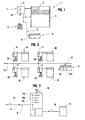
- la figure 1 est une représentation schématisée d'un système de fermeture motorisé, en particulier un volet roulant autorisant la mise en oeuvre du procédé de diagnostic conforme à l'invention ; la figure 2 représente, de manière schématisée, une installation comportant plusieurs de ces systèmes de fermeture motorisés ; la figure 3 est une représentation schématisée d'un exemple de réalisation d'un outil de test, plus particulièrement adapté pour tester une installation telle que représentée dans la figure 2.
- Figure 1 is a schematic representation of a motorized closure system, in particular a shutter allowing the implementation of the diagnostic method according to the invention; Figure 2 shows schematically an installation comprising several of these motorized closure systems; FIG. 3 is a schematic representation of an exemplary embodiment of a test tool, more particularly adapted for testing an installation as represented in FIG. 2.
Tel que représenté dans les figures 1 et 2, la présente invention a trait au domaine des systèmes de fermeture motorisés plus particulièrement destinés au bâtiment. Ainsi, ces systèmes ont été représentés, de manière indicative sous forme de volets roulants 1 ; 1A, 1B, 1C, 1D auxquels est associé, individuellement, un boîtier de commande 2 ; 2A, 2B, 2C, 2D. La liaison entre ce boîtier de commande sur lequel est destiné à intervenir l'usager et le volet roulant correspondant peut être du type filaire ou peut être assurée, comme cela se fait habituellement, par transmission radio, infrarouge ou similaire.As shown in Figures 1 and 2, the present invention relates to the field of motorized closure systems specifically for the building. Thus, these systems have been shown, indicatively in the form of shutters 1; 1A, 1B, 1C, 1D with which is associated, individually, a
Il est évident que le dysfonctionnement d'un tel volet roulant 1 ; 1A, 1B, 1C, 1D peut avoir différentes origines et, notamment, il peut être lié à des problèmes électriques ou électroniques au niveau de la gestion du fonctionnement du moteur 3. En particulier à de tels moteurs électriques 3 est associée, usuellement, une sécurité thermique 4 qui peut être, à elle seule, à l'origine de la panne. De même, ces volets roulants 1 ; 1A, 1B, 1C, 1D sont souvent équipés d'un capteur 5 de détection d'obstacle associé, soit à la dernière lame du tablier, soit à une coulisse latérale. Ce capteur, s'il est défectueux, peut, lui aussi, empêcher le fonctionnement de ce volet roulant. Mais les problèmes peuvent être liés à une simple coupure d'alimentation électrique, au niveau de ce volet roulant ou encore du boîtier de commande fonctionnant souvent à l'aide d'une pile.It is obvious that the malfunction of such a shutter 1; 1A, 1B, 1C, 1D can have different origins and, in particular, it can be related to electrical or electronic problems in the management of the operation of the engine 3. In particular to such electric motors 3 is associated, usually, a thermal safety 4 which can be, alone, the cause of the failure. Similarly, these shutters 1; 1A, 1B, 1C, 1D are often equipped with an associated
Aussi, selon l'invention, il a été imaginé un procédé de diagnostic de fonctionnement d'au moins un de ces systèmes de fermeture motorisés consistant :
- à enregistrer sous forme codée électroniquement, au niveau d'une
mémoire 6 d'une unité degestion 7 du fonctionnement du moteur 3 dudit système 1 ; 1A, 1B, 1C, 1D, un ou plusieurs événements liés au fonctionnement dudit moteur 3, le cas échéant au travers de capteurs appropriés ; - à raccorder à ladite unité de
gestion 7 par l'intermédiaire de moyens deraccordement 8 filaires ou non, un outil detest 9 apte à lire le contenu des données stockées enmémoire 6 ; - et, en fin de compte, à interpréter les données recueillies au travers d'une unité de traitement interne ou externe à l'outil de test afin d'émettre une information claire pour un opérateur sur la nature du ou des défauts détectés.
- to record in electronic coded form, at a
memory 6 of amanagement unit 7 of the operation of the engine 3 of said system 1; 1A, 1B, 1C, 1D, one or more events related to the operation of said motor 3, where appropriate through appropriate sensors; - to connect to said
management unit 7 via connecting means 8 wire or not, atest tool 9 able to read the contents of the data stored inmemory 6; - and, ultimately, interpreting the collected data through a processing unit internal or external to the test tool to emit clear information to an operator about the nature of the detected fault (s).
La mémoire 6 d'une unité de gestion 7 peut être subdivisée en autant de compteurs de défaut que l'on souhaite. En particulier, il peut être enregistré, sous forme codée électroniquement, le nombre de fois que le fonctionnement du moteur 3 a été interrompu sous l'influence de la sécurité thermique 4 ou d'un capteur de présence d'obstacle 5, voire le nombre de fois que ce moteur 3 a été arrêté, tout simplement, par l'intermédiaire des détecteurs de fin de course.The
De même il peut être enregistré dans la mémoire 6, tout paramètre capable de donner une indication sur les conditions de fonctionnement de ce moteur 3, en particulier si l'un de ses bobinages est ou non défaillant.Similarly it can be stored in the
La mémoire 6 peut encore être prévue apte à enregistrer les différents événements relatifs à la transmission d'un ordre en provenance du boîtier de commande 2 ; 2A, 2B, 2C, 2D.The
Le procédé de diagnostic selon l'invention prévoit, encore, une étape consistant à raccorder l'outil de test 9, de manière filaire ou non filaire, audit boîtier de commande 2 afin d'enregistrer un ordre transmis au travers de ce dernier, simultanément, l'ordre perçu par l'unité de gestion 7 du système de fermeture motorisé en vue d'identifier un défaut de transmission.The diagnostic method according to the invention provides, again, a step of connecting the
Dans le cadre d'une configuration comme visible dans la figure 2, correspondant à une installation regroupant plusieurs systèmes de fermeture motorisés, ici représentés sous forme de volets roulants 1A, 1B, 1C, 1D auxquels il est possible de transmettre un ordre groupé, soit par l'intermédiaire d'un boîtier de commande spécifique ou encore au travers de l'un quelconque des boîtiers de commande 2A, 2B, 2C, 2D correspondant à chacun de ces volets roulants 1A, 1B, 1C, 1D, il est prévu, préférentiellement, de capter, par l'intermédiaire de moyens de raccordement filaire ou non reliant l'outil de test 9 à ce boîtier de commande concerné, l'ordre de commande groupé transmis pour aller le comparer à l'ordre reçu par les différents volets et enregistré au niveau de leur mémoire respective 6 dont l'outil de test 9 est capable de lire le contenu.In the context of a configuration as shown in Figure 2, corresponding to an installation comprising several motorized locking systems, here represented in the form of
Le procédé conforme à l'invention et le fonctionnement de l'outil de test permettant sa mise en oeuvre seront mieux compris au vu de la description qui va suivre se rapportant précisément à cette figure 2 représentant plusieurs volets roulants 1A, 1B, 1C, 1D auxquels est associé un boîtier de commande 2A, 2B, 2C, 2D permettant de leur transmettre, au moins, un ordre de commande d'ouverture ou de fermeture. Tout particulièrement, la transmission entre un boîtier de commande et un volet roulant s'effectue par ondes hertziennes, infrarouges ou similaires.The method according to the invention and the operation of the test tool for its implementation will be better understood from the following description relating specifically to this FIG. 2 represents
Par ailleurs, ces volets roulants 1A, 1B, 1C, 1D sont reliés à un réseau d'alimentation électrique 13 au travers duquel ils sont à même de se transmettre des informations par courant porteur. En particulier, depuis un boîtier de commande 2A, 2B, 2C, 2D il est possible au travers d'un ordre transmis au volet roulant qui lui est directement associé, respectivement 1A, 1B, 1C, 1D, de communiquer avec les autres volets roulants du groupe ou à un sous-groupe de volets roulants en vue d'assurer la commande de fermeture et/ou d'ouverture, simultanément, de plusieurs volets roulants depuis un tel boîtier de commande 2A, 2B, 2C, 2D.Moreover, these
A noter qu'une telle configuration permet également à ces autres volets roulants commandés depuis un boîtier de commande déterminé, de transmettre une information en retour, par exemple, une information de bonne exécution d'ordre.Note that such a configuration also allows these other roller shutters controlled from a specific control unit, to transmit feedback information, for example, a good order execution information.
Dans une telle configuration, le procédé de diagnostic consiste donc à enregistrer sous forme codée électroniquement au niveau de la mémoire 6 des unités de gestion 7 du fonctionnement du moteur 3 de chacun des volets roulants des événements concernant ce dernier, en particulier, l'état dans lequel se trouve ce volet roulant, ouvert ou fermé, le nombre est l'origine des différentes commandes d'arrêt de fonctionnement du moteur 3 etc.... Au niveau de cette mémoire 6 est encore enregistrée la nature de l'ordre dernièrement reçu au travers du boîtier de commande associé, ainsi que, le cas échéant, la nature du dernier ordre qui a été transmis par courant porteur par un autre volet roulant. Le procédé consiste, alors, à raccorder à ladite unité de gestion 7 de chacun de ces volets roulants 1A, 1B, 1C, 1D un outil de test 9 par l'intermédiaire de moyens de raccordement 8 qui se présentent, avantageusement, sous forme d'une prise secteur 14 apte à être raccordée par courant porteur, à ces volets roulants. En effet, dans une telle configuration ceux-ci comportent, nécessairement, des moyens de cryptage et de décryptage pour, précisément, selon le cas émettre sur ce réseau d'alimentation électrique 13 un train d'information destiné à d'autres volets roulants ou, au contraire, recevoir et décrypter une information transmise par courant porteur et qui leur est destinée.In such a configuration, the diagnostic method therefore consists in recording in electronically coded form at the level of the
Bien entendu, l'outil de test 9 comporte, alors, lui aussi, une telle unité de cryptage-décryptage 15 pour communiquer au travers de ce réseau 13 avec les volets roulants 1A, 1B, 1C, 1D ceci, à la fois, pour aller lire le contenu de leur mémoire 6 ou encore pour détecter une quelconque transmission par courant porteur.Of course, the
Il est encore possible d'envisager des moyens de raccordement 8 non filaires entre l'outil de test 9 et ces unités de gestion 7 des volets roulants 1A, 1B, 1C, 1D, en particulier si ces derniers sont en liaison entre eux par de tels moyens de transmission non filaires.It is still possible to envisage non-wired connection means 8 between the
Dans la mesure où un boîtier de commande 2A, 2B, 2C, 2D communique avec son volet roulant 1A, 1B, 1C, 1D par ondes radio ou similaires et que, par conséquent, ledit volet roulant 1 est nécessairement équipé d'un récepteur adapté, lesdits moyens de raccordement 8 peuvent encore se présenter sous forme d'un émetteur associé à l'outil de test 9 lequel est alors en mesure de transmettre une information au récepteur de l'unité de gestion 7 d'un volet roulant 1A, 1B, 1C, 1D déterminé. Une fois cette transmission établie, ce même outil de test peut communiquer avec chacun des autres volets roulants par courant porteur et en se servant de l'unité de cryptage et de décryptage équipant nécessairement le volet roulant avec lequel il communique directement.Insofar as a
A l'inverse, en vue de recueillir les informations, au niveau de cet outil de test 9, des données en mémoire 6 de chacun des volets roulants 1A, 1B, 1C, 1D, il suffit d'équiper ledit volet roulant avec lequel il communique directement, par ondes hertziennes, infrarouges ou autres, d'un émetteur apte à transmettre, à un récepteur de l'outil de test 9, lesdites données correspondant à ce même volet roulant, mais aussi les données des mémoires des autres volets roulants recueillies par courant porteur.Conversely, in order to gather information, at the level of of this
En particulier, l'on peut faire appel au récepteur dont est nécessairement équipé un tel volet roulant pour s'en servir comme émetteur en commandant le pilotage de l'oscillateur de ce récepteur par l'intermédiaire du microcontrôleur 10 que comporte une unité de gestion 7.In particular, it is possible to use the receiver which is necessarily equipped with such a shutter to use it as a transmitter by controlling the control of the oscillator of this receiver via the
Finalement, l'émetteur de l'outil de test 9 vient tout d'abord transmettre, par l'intermédiaire du récepteur du volet roulant, un ordre d'envoi des informations au microcontrôleur 10, lequel microcontrôleur 10, en venant s'exécuter, assure le pilotage de l'oscillateur du récepteur pour cette transmission des informations demandées. Pour que cela fonctionne, il suffit d'approcher suffisamment près cet outil de test 9 du volet roulant auquel il est destiné à être connecté directement sachant que la connexion aux autres volets roulants s'effectue au travers de ce même volet roulant, par courant porteur.Finally, the emitter of the
Dans une telle configuration cet outil de test 9 comporte, malgré tout, des moyens de connexion au réseau d'alimentation électrique 13, afin, d'une part, de mesurer le degré de pollution de ce réseau. Ceci consiste à détecter si un signal courant porteur autre que ceux que se transmettent les systèmes de fermeture est susceptible de perturber le fonctionnement de ces derniers.In such a configuration, this
Une telle connexion permet, encore, de procéder à une comparaison entre des signaux courants porteurs transmis entre les volets roulants et ceux perçus et enregistrés au niveau de leur mémoire 6 respective.Such a connection makes it possible, again, to make a comparison between current carrier signals transmitted between the shutters and those perceived and recorded at their
De la même manière cet outil de test 9 comporte, avantageusement, des moyens récepteurs d'ondes 16 de nature identique à la communication existant entre un boîtier de commande 2 ; 2A, 2B, C et un volet roulant 1 ; 1A, 1B, 1C, 1D, voire entre les différents volets roulants si ceux-ci sont destinés à communiquer entre eux autrement que par voie filaire, de manière à détecter si dans l'environnement où intervient une transmission par ondes radio, infrarouges ou autres, n'est pas pollué par des ondes parasitaires ne sont pas capables de perturber cette communication.In the same way, this
L'outil de test 9 peut être pourvu de moyens de visualisation 11 capables d'informer l'usager de la nature du ou des défauts identifiés au travers des données relevées dans les mémoires 6 des volets roulants ou encore des différents phénomènes perturbants détectés.The
Avantageusement, de tels moyens de visualisation 11 empruntent une configuration simple d'une pluralité de voyants 11A, 11B, 11C ... auxquels est associée une légende claire permettant une interprétation rapide. En particulier, l'outil de test 9 comporte, dans ce cas, une unité de traitement interne 12A, laquelle est capable de décrypter le contenu des mémoires 6 ou, encore d'interpréter d'autres mesures pour commander l'allumage ou l'extension de tel ou tel voyant 11A, 11B, 11C constituant une information directe pour cet opérateur.Advantageously, such viewing means 11 take a simple configuration of a plurality of
Toutefois, cet outil de test 9 peut encore être raccordé à une unité de traitement 12 externe. Dans ce cas d'espèce cet outil de test 9 pourra être équipé, avantageusement, d'un modem 17 pour la transmission, par un réseau de télécommunication 18, des informations qu'il aura recueillies au cours d'un cycle de test. Cela permet d'envisager, en particulier, une maintenance à distance d'une telle installation regroupant plusieurs systèmes de fermeture motorisés.However, this
Claims (8)
- Process for diagnosing the operation of one or several motorised closing systems (1 ; 1A, 1B, 1C, 1D) each comprising a motor (3), in particular for a roller blind, characterised in that:- at the level of a memory (6) of a control unit (7) for the operation of the motor (3) of said system (1 ; 1A, 1B, 1C, 1D) are stored, in an electronically encoded way, one or several events related to the operation of this motor (3) ;- to said control unit (7) is connected, through cable or wireless connecting means (8), a test tool (9) capable of reading the contents of the data in the memory (6) ;- there is proceeded to interpreting the data collected through a processing unit internal (12A) or external (12) to the test' tool (9), in order to transmit a clear information for an operator on the nature of the detected default or defaults.
- Diagnostic process according to claim 1, characterised in that :- in the memory (6) of the control unit {7) of a motorised closing system (1 ; 1A, 1B, 1C, 1D) is also stored the order transmitted from a control casing (2 ; 2A, 2B, 2C, 2D) ;- the test tool (9) is connected by cable or wireless to said control casing (2 ; 2A, 2B, 2C, 2D), in order to store an order transmitted through the latter, with a view to identifying a transmission default.
- Diagnostic process according to claim 1 or 2, characterised in that the user is informed on the nature of the default or defaults identified through the data stored in the memories (6) of the control unit (7) of the motorised closing systems (1 ; 1A, 1B, 1C, 1D) or also on the various detected disturbing phenomena by means of a plurality of signal lamps (11A, 11B, 11C) to which is associated a clear legend for interpretation at the level of the test tool (9).
- Diagnostic process according to any of the preceding claims, characterised in that communication with the test tool (9) occurs through wave-receiving means (16) of an identical nature as the communication between a control casing (2 ; 2A, 2B, 2C, 2D) and a motorised closing system (1 ; 1A, 1B, 1C, 1D) and/or between various motorised closing systems (1 ; 1A, 1B, 1C, 1D), with a view to detecting the emission of spurious waves.
- Diagnostic process according to any of the preceding claims, characterised in that the information collected by the test tool (9) during a cycle is transmitted by a telecommunication network (18) thanks to a modem.
- Diagnostic process according to any of the preceding claims, characterised in that communication with the test tool (9) occurs by carrier current and by means of an adapted encrypting and decrypting unit, through the electric-current supply network of said system (1 ; 1A, 1B, 1C, 1D).
- Diagnostic process according to any of claims 1 to 5, characterised in that :- to the microcontroller (10) of the control unit (7) is transmitted, through a transmitter associated to this test tool (9), an order for sending at least the information contained in its memory (6) ;- and the control, through this microcontroller (10), of the oscillator of a receiver a motorised closing system (1 ; 1A, 1B, 1C, 1D) comprised for receiving a transmission from the transmitter of a control casing (2 ; 2A, 2B, 2C, 2D), with a view to the transmission by this receiver of the requested information.
- Diagnostic process according to any of the preceding claims, characterised in that the various motorised closing systems (1 ; 1A, 1B, 1C, 1D) are connected by carrier current and the test tool (9) is connected to one of the systems for reading, through this system, the contents of the memory (6) of the control unit (7) corresponding to each of the motorised closing systems (1A, 1B, 1C, 1D).
Applications Claiming Priority (2)
| Application Number | Priority Date | Filing Date | Title |
|---|---|---|---|
| FR9903992A FR2791796B1 (en) | 1999-03-29 | 1999-03-29 | DIAGNOSTIC METHOD AND TOOL FOR TESTING THE OPERATION OF AT LEAST ONE MOTORIZED CLOSING SYSTEM, SUCH AS A ROLLING SHUTTER OR THE LIKE |
| FR9903992 | 1999-03-29 |
Publications (2)
| Publication Number | Publication Date |
|---|---|
| EP1041238A1 EP1041238A1 (en) | 2000-10-04 |
| EP1041238B1 true EP1041238B1 (en) | 2006-05-31 |
Family
ID=9543831
Family Applications (1)
| Application Number | Title | Priority Date | Filing Date |
|---|---|---|---|
| EP20000440067 Expired - Lifetime EP1041238B1 (en) | 1999-03-29 | 2000-03-08 | Diagnostic process for testing the functioning of at least a motorised closing system, like a roller shutter or comparable |
Country Status (4)
| Country | Link |
|---|---|
| EP (1) | EP1041238B1 (en) |
| DE (1) | DE60028279T2 (en) |
| ES (1) | ES2265329T3 (en) |
| FR (1) | FR2791796B1 (en) |
Families Citing this family (2)
| Publication number | Priority date | Publication date | Assignee | Title |
|---|---|---|---|---|
| WO2002064938A1 (en) * | 2001-02-15 | 2002-08-22 | Alfred Schellenberg Gmbh | Device and method for controlling the strap of a roller blind |
| CN103954466B (en) * | 2014-05-07 | 2016-04-13 | 青岛富维特交通设备有限公司 | A kind of roller shutter fatigue experimental device |
Family Cites Families (4)
| Publication number | Priority date | Publication date | Assignee | Title |
|---|---|---|---|---|
| EP0453399A1 (en) * | 1990-04-17 | 1991-10-23 | Somfy | Installation with a plurality of receivers and transmitters |
| EP0513443B1 (en) * | 1991-05-06 | 1999-11-17 | Koninklijke Philips Electronics N.V. | Building management system |
| DE4312613A1 (en) * | 1993-04-19 | 1994-10-20 | Abb Patent Gmbh | Electronic control module (chip) for driving actuating elements |
| DE19717089C1 (en) * | 1997-04-23 | 1998-10-08 | Geyer Ag | System for comfortable, mobile operation, monitoring and data exchange |
-
1999
- 1999-03-29 FR FR9903992A patent/FR2791796B1/en not_active Expired - Fee Related
-
2000
- 2000-03-08 ES ES00440067T patent/ES2265329T3/en not_active Expired - Lifetime
- 2000-03-08 EP EP20000440067 patent/EP1041238B1/en not_active Expired - Lifetime
- 2000-03-08 DE DE2000628279 patent/DE60028279T2/en not_active Expired - Fee Related
Also Published As
| Publication number | Publication date |
|---|---|
| FR2791796A1 (en) | 2000-10-06 |
| DE60028279D1 (en) | 2006-07-06 |
| DE60028279T2 (en) | 2007-07-05 |
| ES2265329T3 (en) | 2007-02-16 |
| EP1041238A1 (en) | 2000-10-04 |
| FR2791796B1 (en) | 2001-08-03 |
Similar Documents
| Publication | Publication Date | Title |
|---|---|---|
| EP2130100B1 (en) | Method for configuring a home automation installation and tool for implementing same | |
| EP1045356A1 (en) | Controlling actuators with transmitters possesing an identity number | |
| FR2966626A1 (en) | METHOD FOR OPERATING A MOBILE CONTROL UNIT OF A DOMOTIC INSTALLATION | |
| EP1041238B1 (en) | Diagnostic process for testing the functioning of at least a motorised closing system, like a roller shutter or comparable | |
| EP3275129B1 (en) | Universal communication system for measurement apparatuses, method of communication relating thereto | |
| WO2003069794A2 (en) | Method for defining a group from among bi-directional objects | |
| FR2565714A1 (en) | Remote monitoring and management method and system used and consulted by videotex terminal | |
| FR2837965A1 (en) | METHOD FOR CONTROLLING AND CONTROLLING THE DYNAMIC OPERATION OF AN ACTUATOR AND THE ASSOCIATED DEVICE | |
| FR2687523A1 (en) | AUDIOVISUAL PROGRAMS BROADCASTING SYSTEM. | |
| FR2891635A1 (en) | SYSTEM FOR CONTROLLING THE TEMPERATURE IN A LOCAL, USING A RADIATOR, ESPECIALLY ELECTRICAL. | |
| EP3367184B1 (en) | Method for configuring a home-automation sensor and home-automation sensor implementing such a method | |
| EP3140961B1 (en) | Optimised method for regulating the electrical consumption of electrical units | |
| EP2919421B1 (en) | Ethernet switch, mobile machine and passenger bus including said Ethernet switch | |
| EP2269176A2 (en) | Device for monitoring a facility provided with camera | |
| EP1172516B1 (en) | Control device of a roller shutter | |
| FR2956769A1 (en) | METHOD FOR CONFIGURING A DOMOTIC FACILITY COMPRISING A FIRST EQUIPMENT AND A SECOND EQUIPMENT SUITABLE TO COMMUNICATE WITH THE OTHER | |
| EP2881923B1 (en) | Universal home-automation system | |
| EP1447518A1 (en) | Method for controlling a motorised closure for a passage | |
| EP0568420B1 (en) | Programmable interface, especially for control of domestic appliances | |
| FR3077086A1 (en) | MANAGEMENT OF THE COMBINED MOVEMENT OF TWO MOTORIZED VANS IN CASE OF AN OBSTACLE ENCOUNTERED BY ONE OF THE VANS. | |
| FR2814774A1 (en) | Remote actuation method for security shutter or blind has emitter to pass signals to shutter motor via transmission with secondary safety circuit | |
| EP1343276B1 (en) | System for diagnosing the state of a data network between different nodes in a vehicle | |
| FR2922016A1 (en) | Water leakage detector i.e. water presence sensor, for use in bathroom of hotel, has electrodes acting as interrupters, where interrupters are opened during absence of water between electrodes and are closed during presence of water | |
| BE1023874A1 (en) | Closure control device by home automation system | |
| EP4129421A1 (en) | Assembly comprising a system for securing and at least one electric or hybrid electric vehicle |
Legal Events
| Date | Code | Title | Description |
|---|---|---|---|
| PUAI | Public reference made under article 153(3) epc to a published international application that has entered the european phase |
Free format text: ORIGINAL CODE: 0009012 |
|
| AK | Designated contracting states |
Kind code of ref document: A1 Designated state(s): DE ES FR IT |
|
| AX | Request for extension of the european patent |
Free format text: AL;LT;LV;MK;RO;SI |
|
| 17P | Request for examination filed |
Effective date: 20010110 |
|
| AKX | Designation fees paid |
Free format text: DE ES FR IT |
|
| 17Q | First examination report despatched |
Effective date: 20031107 |
|
| GRAP | Despatch of communication of intention to grant a patent |
Free format text: ORIGINAL CODE: EPIDOSNIGR1 |
|
| RTI1 | Title (correction) |
Free format text: DIAGNOSTIC PROCESS FOR TESTING THE FUNCTIONING OF AT LEAST A MOTORISED CLOSING SYSTEM, LIKE A ROLLER SHUTTER OR COMPARABLE |
|
| GRAS | Grant fee paid |
Free format text: ORIGINAL CODE: EPIDOSNIGR3 |
|
| GRAA | (expected) grant |
Free format text: ORIGINAL CODE: 0009210 |
|
| AK | Designated contracting states |
Kind code of ref document: B1 Designated state(s): DE ES FR IT |
|
| PG25 | Lapsed in a contracting state [announced via postgrant information from national office to epo] |
Ref country code: IT Free format text: LAPSE BECAUSE OF FAILURE TO SUBMIT A TRANSLATION OF THE DESCRIPTION OR TO PAY THE FEE WITHIN THE PRESCRIBED TIME-LIMIT;WARNING: LAPSES OF ITALIAN PATENTS WITH EFFECTIVE DATE BEFORE 2007 MAY HAVE OCCURRED AT ANY TIME BEFORE 2007. THE CORRECT EFFECTIVE DATE MAY BE DIFFERENT FROM THE ONE RECORDED. Effective date: 20060531 |
|
| REF | Corresponds to: |
Ref document number: 60028279 Country of ref document: DE Date of ref document: 20060706 Kind code of ref document: P |
|
| REG | Reference to a national code |
Ref country code: ES Ref legal event code: FG2A Ref document number: 2265329 Country of ref document: ES Kind code of ref document: T3 |
|
| PLBE | No opposition filed within time limit |
Free format text: ORIGINAL CODE: 0009261 |
|
| STAA | Information on the status of an ep patent application or granted ep patent |
Free format text: STATUS: NO OPPOSITION FILED WITHIN TIME LIMIT |
|
| 26N | No opposition filed |
Effective date: 20070301 |
|
| PGFP | Annual fee paid to national office [announced via postgrant information from national office to epo] |
Ref country code: IT Payment date: 20080327 Year of fee payment: 9 |
|
| PGFP | Annual fee paid to national office [announced via postgrant information from national office to epo] |
Ref country code: DE Payment date: 20080306 Year of fee payment: 9 Ref country code: ES Payment date: 20080418 Year of fee payment: 9 |
|
| PGFP | Annual fee paid to national office [announced via postgrant information from national office to epo] |
Ref country code: FR Payment date: 20080326 Year of fee payment: 9 |
|
| REG | Reference to a national code |
Ref country code: FR Ref legal event code: ST Effective date: 20091130 |
|
| PG25 | Lapsed in a contracting state [announced via postgrant information from national office to epo] |
Ref country code: DE Free format text: LAPSE BECAUSE OF NON-PAYMENT OF DUE FEES Effective date: 20091001 |
|
| PG25 | Lapsed in a contracting state [announced via postgrant information from national office to epo] |
Ref country code: FR Free format text: LAPSE BECAUSE OF NON-PAYMENT OF DUE FEES Effective date: 20091123 |
|
| REG | Reference to a national code |
Ref country code: ES Ref legal event code: FD2A Effective date: 20090309 |
|
| PG25 | Lapsed in a contracting state [announced via postgrant information from national office to epo] |
Ref country code: ES Free format text: LAPSE BECAUSE OF NON-PAYMENT OF DUE FEES Effective date: 20090309 |
|
| PG25 | Lapsed in a contracting state [announced via postgrant information from national office to epo] |
Ref country code: IT Free format text: LAPSE BECAUSE OF NON-PAYMENT OF DUE FEES Effective date: 20090308 |