EP1038746A2 - Bremsvorrichtung für Fahrzeuge - Google Patents
Bremsvorrichtung für Fahrzeuge Download PDFInfo
- Publication number
- EP1038746A2 EP1038746A2 EP00104603A EP00104603A EP1038746A2 EP 1038746 A2 EP1038746 A2 EP 1038746A2 EP 00104603 A EP00104603 A EP 00104603A EP 00104603 A EP00104603 A EP 00104603A EP 1038746 A2 EP1038746 A2 EP 1038746A2
- Authority
- EP
- European Patent Office
- Prior art keywords
- brake
- flow
- braking device
- wheel brake
- hydraulic fluid
- Prior art date
- Legal status (The legal status is an assumption and is not a legal conclusion. Google has not performed a legal analysis and makes no representation as to the accuracy of the status listed.)
- Withdrawn
Links
Images



Classifications
-
- B—PERFORMING OPERATIONS; TRANSPORTING
- B60—VEHICLES IN GENERAL
- B60T—VEHICLE BRAKE CONTROL SYSTEMS OR PARTS THEREOF; BRAKE CONTROL SYSTEMS OR PARTS THEREOF, IN GENERAL; ARRANGEMENT OF BRAKING ELEMENTS ON VEHICLES IN GENERAL; PORTABLE DEVICES FOR PREVENTING UNWANTED MOVEMENT OF VEHICLES; VEHICLE MODIFICATIONS TO FACILITATE COOLING OF BRAKES
- B60T17/00—Component parts, details, or accessories of power brake systems not covered by groups B60T8/00, B60T13/00 or B60T15/00, or presenting other characteristic features
- B60T17/04—Arrangements of piping, valves in the piping, e.g. cut-off valves, couplings or air hoses
-
- B—PERFORMING OPERATIONS; TRANSPORTING
- B60—VEHICLES IN GENERAL
- B60T—VEHICLE BRAKE CONTROL SYSTEMS OR PARTS THEREOF; BRAKE CONTROL SYSTEMS OR PARTS THEREOF, IN GENERAL; ARRANGEMENT OF BRAKING ELEMENTS ON VEHICLES IN GENERAL; PORTABLE DEVICES FOR PREVENTING UNWANTED MOVEMENT OF VEHICLES; VEHICLE MODIFICATIONS TO FACILITATE COOLING OF BRAKES
- B60T11/00—Transmitting braking action from initiating means to ultimate brake actuator without power assistance or drive or where such assistance or drive is irrelevant
- B60T11/10—Transmitting braking action from initiating means to ultimate brake actuator without power assistance or drive or where such assistance or drive is irrelevant transmitting by fluid means, e.g. hydraulic
Definitions
- the invention relates to a braking device for vehicles according to the preamble of claim 1.
- a pressure medium brake system of a wheeled vehicle goes for example from DE 32 46 651 A1.
- This pressure medium brake system has a control cylinder, one brake cylinder for each vehicle wheel and one Line on which the control cylinder with the brake cylinder connects.
- a throttle device provided so as to transmit vibrations, Pulsations or the like, for example not completely circular brake drums, brake discs or brake pads can be transferred, too prevent, or to block at a quick Avoid applying the brakes.
- Hydraulic fluids are used in such braking devices for vehicles hygroscopic liquids used on polyglycol ether basis, due to their Hygroscopicity should prevent water residue due to ice formation below freezing or Vapor formation above the boiling point the braking effect affect or brake the vehicle make it completely inoperable.
- All brake devices for vehicles are next to Tubes also lead to brake hoses leading to the wheel brake cylinders provided for flexibility of the brake line ensure.
- These brake hoses are now if only to a small extent, permeable to water.
- the absorption of water in the brake fluid leads a lowering of the boiling point of the brake fluid, which is the main reason for changing the brake fluid is at predetermined time intervals.
- Brake hoses on most brake devices for Vehicles provided near the wheel brake cylinders water absorption occurs in this area and a resulting lowering of the boiling point Brake fluid on.
- the change in brake fluid is located in the area of the wheel brake cylinder, because with each braking operation only one back and forth and the brake fluid moves back and so after an iteration (back and forth shift) restores the original state.
- the object of the invention is to provide a braking device for Train vehicles in such a way that the localization the disturbing water absorption of the hydraulic or brake fluid as far as possible in the area of the wheel brake cylinders avoided and thus an extension of the maintenance intervals for replacing the brake fluids is achieved.
- This task is done with a braking device for vehicles of the generic type by the features of Claim 1 solved and has the advantage that at least one, preferably adjacent to the wheel brake cylinders arranged device for non-vanishing Difference formation of the flow profiles for the back and forth flow of the hydraulic fluid if necessary involving a turbulent flow through a transport of the hydraulic fluid achieved thereby a localization of with water hydraulic fluid and therefore a local one Lowering of the boiling point of the brake fluid in the area the wheel brake cylinder is largely avoided.
- the flow profiles of the hydraulic fluid are pre-chambers assigned to the wheel brake cylinders, the one in the direction of flow and / or perpendicular to Flow direction arranged asymmetry. This asymmetry results in different ones Flow profiles when the hydraulic fluid flows back and forth and thereby a non-vanishing Flow profile in one iteration (one round trip Backflow), which occurs with each further interation reinforced.
- the prechamber is in Flow direction initially divergent and then convergent or vice versa. It therefore follows in the fluidic sense a diffuser is a convergent Place, or vice versa, the two together an optimal successive formation of a flow profile with non-vanishing difference formation of the Lead back and forth.
- the antechamber is designed so that it in Flow direction has no undercuts. On this way it is avoided that in the antechamber Filling bubbles can remain, or when emptying of the brake system fluid remains in the antechamber.
- At least two electrical conductors are arranged during the Relaxation process of the wheel brake cylinders for generation of an inhomogeneous electric field inside the Brake hose with a potential difference become.
- the electrical conductors can be used for The effect can be shaped arbitrarily.
- a wire is arranged inside a brake pipe during the relaxation process Wheel brake cylinder for generating an inhomogeneous electrical Field inside the brake pipe with a potential difference to the pipe is applied.
- the wire can be shaped to increase the effect or can be laid as desired, e.g. meandering or spiral.
- the non-vanishing difference of the flow profiles possibly including a turbulent flow by electromagnetic means use of the phenomenon that polarisable Matter or matter with a permanent dipole moment, that is, with a dielectric constant larger as 1, coupled to inhomogeneous electric fields.
- Brake fluids based on polyglycol ether are one such polarizable matter.
- the dielectric constant of brake fluid changes deals with the water input and can even be used Determination of the water content can be used. This But change is for the swirling of the brake fluid not relevant due to inhomogeneous fields. For It is only to achieve the best possible swirling required that the electrical fields in the Brake hose or in the brake line pipe if possible be made inhomogeneous.
- the electrical Fields only when the wheel brake cylinder relaxes switched on. This creates a steady flow the brake fluid when the brake is actuated as well as an uneven when fields are switched on Achieved reflux.
- the flow profiles for the return flow are not identical in this way, so a not disappearing difference formation of the flow profiles the brake fluid is created.
- the brake hose and the brake pipe has a circular cross section exhibit. This will result in a pulsed application with pressure that with an expansion of the Brake hose or the brake pipe connected is a bending stress on the brake hose or of the brake line pipe avoided.
- a circular cross-section arises elliptical cross section only one Tensile stress, but no bending stress, the to cracking and possibly destruction of the Brake hose or the brake line pipe can lead.
- the invention is based on two principles. On the one hand can be achieved that the flow profiles through in a pre-chamber arranged diffusers or by in inhomogeneous electric fields generated in the brake lines, despite laminar back and forth flow, with one There and back flow are different and so too a not disappearing flow profile and thus comes to the liquid transport, on the other hand you can through such diffusers or inhomogeneous electrical Fields ensure that the flow at least in one Direction of flow becomes turbulent and so it additionally in addition to the non-disappearing flow profile mixing occurs due to swirling. The When braking, the flow must remain laminar in order to Flow resistance does not increase and it must be ensured that turbulence only occurs at reflux. Both embodiments are for pipes as well also applicable to hoses.
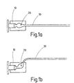
- a wheel brake cylinder 10 shown in FIG. 1a has a prechamber 20 with diffusers into which a brake hose or a brake pipe 30 opens.
- Fig. 2a to 2d schematically shows the formation of a flow profile explained with non-vanishing difference formation.
- FIG. 2a shows schematically two different flow profiles with return flow.
- Fig. 2b schematically the flow profile of the hydraulic fluid with a return flow
- Fig. 2c at two back and forth flows
- Fig. 2d with three back and forth Reverse flows shown.
- 2b to 2d show a non-vanishing difference is formed of the airfoil leading to a coaxial Transport of the hydraulic fluid leads.
- the different Flow profiles for outflow and return flow result in Fig. 2a for example by a laminar flow and turbulent backflow or by an asymmetrical design of the antechamber 20, as is shown schematically with reference to FIGS. 1a, 1b, 3a, 3b is shown.
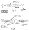
- FIG 3a, 3b The principle of hydraulic fluid transport by a prechamber according to FIG 3a, 3b, which different Formations of such an antechamber 20 schematically show.
- antechambers 20 are shown, which preferably rotationally symmetrical in the direction of flow divergent and subsequently preferred are formed rotationally symmetrically convergent.
- a divergent design of the prechamber 20 results a diffuser effect.
- Fig. 3b is a divergent and then a convergent flow and the result a flow profile with non-vanishing difference formation, as it is schematic in Fig. 3a and 3b left is shown.
- the Flow laminar, as shown in Fig. 3a, or itself with larger opening angles of the divergent area detaches from the wall (3b) or flows turbulently (not shown). If the opening angle is increased further the maximum of the flow profile can also be lean against a wall of the prechamber 20, ie not detach completely from the wall. That state is however not stable.
- the jet of hydraulic fluid In this case, it commutes from a wall back and forth to the other wall.
- the hydraulic fluid is transported and possibly also a swirl through turbulence.
- the volume of the pre-chamber 20 is roughly comparable with the volume of the brake hose or Brake line pipe 30. In this way there is double Amount of brake fluid with the same hose surface, i.e. with the same water input per unit of time to disposal.
- the additional volume is compared to the total amount of the brake fluid circuit Braking device, which in addition to the wheel cylinders and Brake lines the master brake cylinder and the reservoir (not shown) includes neglect.
- the brake fluid column moves when the brakes are applied slightly (around 200 mm) and mixed so with the liquid in the antechamber. As a result, the critical water content, i.e.
- the geometric shape of the prechamber i.e. their flow resistance, their fillability and efficiency in the transport of the brake fluid (see Fig. 1b) or swirling the Brake fluid to be optimized so that at a relaxation process of the wheel brake cylinder a special optimal non-vanishing difference formation the flow profiles or a turbulence turbulence the brake fluid takes place.
- the antechamber 20 is advantageously not only in view on an optimal flow, but also in terms of their Fillability optimized.
- the prechamber 20 can be designed asymmetrically be that there are no undercuts in the direction of flow has and so does not act as a cavity in which Filling air bubbles or the like arise or in which accumulate hydraulic fluid when emptying can.
- FIGS. 4, 5 and 6 Other embodiments of a swirling device are shown in FIGS. 4, 5 and 6.
- a soul in the form of a Elastomer inner tube 50 is provided.
- the soul and the brake hose 40 which is in the form of an elastomer outer tube or a blanket, there are several textile braid inserts 60 arranged to the compressive strength to ensure.
- these textile braid inserts 60 two insulated conductors 70 are now arranged asymmetrically. A potential difference is applied to this conductor 70 created in this way an inhomogeneous electrical Generate field whose field lines 72 in the 4 is shown schematically in FIG are.
- the inhomogeneous electric field is used for coupling the brake fluid based on polyglycol ether exists and in so far a polarizable matter with a dielectric constant ⁇ > 1.
- the inhomogeneous electric field is in a flow direction is switched on, i.e. if the two conductors 70a and 70b have a potential difference applied to them, finds a non-vanishing difference between the Flow profiles and possibly an additional one Turbulence caused by turbulence with a dipole moment coupling brake fluid and thereby a Mixing of the brake fluid instead.
- the electrical Field is preferably always during a relaxation process the wheel brake cylinder is switched on, i.e. when the brake fluid flows back from the Wheel brake cylinders.
- FIG. 5 Another embodiment is shown in FIG. 5. This embodiment differs from that in FIG Fig. 4 shown in that one of the two Wires 80b is formed as a braid that is inside the brake hose 40 is arranged and one another wire 80a is opposite. Through this flat Training one of the two leaders can also be a inhomogeneous field are generated, as shown in Fig. 5 schematically is shown.
- a brake pipe 42 with circular cross section shown which itself of the two heads.
- a further conductor 90 is arranged in the brake pipe 42 .
- the leader 90 and the brake pipe 42 are with a Potential difference applied, so that inside the Brake pipe 42 an inhomogeneous field is formed, as shown schematically in Fig. 4.
- Fig. 4 are like that in connection with FIGS. 5 and 4 described embodiment adjacent to the conductors Areas with less river and further from the ladders removed areas with greater river present. Also This can be done by varying the laying of the ladder the effect can be optimized.
Landscapes
- Engineering & Computer Science (AREA)
- Transportation (AREA)
- Mechanical Engineering (AREA)
- Valves And Accessory Devices For Braking Systems (AREA)
- Braking Arrangements (AREA)
Abstract
Description
- Fig. 1a, 1b
- schematisch zwei Ausführungsbeispiele eines Radbremszylinders einer erfindungsgemäßen Bremsvorrichtung für Fahrzeuge;
- Fig. 2a - 2d
- schematisch das Strömungsprofil einer Strömung mit nicht verschwindender Differenzbildung gemäß vorliegender Erfindung aufgrund einer laminaren Hinströmung und einer turbulenten Rückströmung;
- Fig. 3a, 3b
- zwei unterschiedliche Ausführungsformen einer Vorkammer mit senkrecht zur Strömungsrichtung asymmetrischer Gestaltung und die darin strömende Hydraulikflüssigkeit aufgrund von laminarer Hin- und Rückströmung mit und ohne Ablösung von der Wand;
- Fig. 4
- eine schaubildliche und eine Schnittansicht eines Bremsschlauchs einer anderen erfindungsgemäßen Bremsvorrichtung;
- Fig. 5
- schematisch eine Schnittdarstellung einer weiteren Ausführungsform eines Bremsschlauchs einer erfindungsgemäßen Bremsvorrichtung und
- Fig. 6
- schematisch eine Schnittdarstellung eines Bremsleitungsrohrs einer erfindungsgemäßen Bremsvorrichtung.
Claims (7)
- Bremsvorrichtung für Fahrzeuge umfassend einen Hauptbremszylinder und mit diesem über Bremsleitungen (30) verbundene Radbremszylinder (10), eine Hydraulikflüssigkeit, mittels der die Radbremszylinder (10) durch Betätigen des Hauptbremszylinders mit Druck beaufschlagbar sind, gekennzeichnet durch wenigstens eine vorzugsweise benachbart zu den Radbremszylindern (10) angeordnete Einrichtung (20; 70a, 70b; 80a, 80b; 42, 90) zur nicht verschwindenden Differenzbildung der Strömungsprofile der Hin- und Rückströmung der Hydraulikflüssigkeit zur Ausbildung eines Transports der Hydraulikflüssigkeit.
- Bremsvorrichtung nach Anspruch 1, dadurch gekennzeichnet, daß die Einrichtung zur nicht verschwindenden Differenzbildung der Strömungsprofile eine den Radbremszylindern (10) zugeordnete Vorkammer (20), die eine in Strömungsrichtung und/oder senkrecht zur Strömungsrichtung angeordnete Unsymmetrie aufweist.
- Bremsvorrichtung nach Anspruch 2, dadurch gekennzeichnet, daß die Vorkammer (20) in Strömungsrichtung zunächst divergent und darauffolgend konvergent oder vice versa ausgebildet ist.
- Bremsvorrichtung nach Anspruch 2, dadurch gekennzeichnet, daß die Vorkammer (20) so unsymmetrisch ausgebildet ist, daß sie in Strömungsrichtung keine Hinterschnitte aufweist.
- Bremsvorrichtung nach Anspruch 1, dadurch gekennzeichnet, daß die Einrichtung zur nicht verschwindenden Differenzbildung der Strömungsprofile wenigstens zwei im Mantel eines Bremsschlauchs (50) angeordnete elektrische Leiter (70a, 70b; 80a, 80b) sind, die während des Entspannungsvorgangs der Radbremszylinder zur Erzeugung eines inhomogenen elektrischen Felds im Inneren des Bremsschlauchs (50) mit einer Potentialdifferenz beaufschlagbar sind.
- Bremsvorrichtung nach Anspruch 1, dadurch gekennzeichnet, daß die Einrichtung zur nicht verschwindenden Differenzbildung der Strömungsprofile ein im Inneren eines Bremsleitungsrohrs (42) angeordneter Draht (90) ist, der relativ zu dem Bremsleitungsrohr (42) während der Entspannungsvorgänge der Radbremszylinder mit einer Potentialdifferenz beaufschlagbar ist.
- Bremsvorrichtung nach Anspruch 5 oder 6, dadurch gekennzeichnet, daß der Bremsschlauch (50) bzw. das Bremsleitungsrohr (42) einen kreisrunden Querschnitt aufweisen.
Applications Claiming Priority (2)
| Application Number | Priority Date | Filing Date | Title |
|---|---|---|---|
| DE1999112886 DE19912886B4 (de) | 1999-03-23 | 1999-03-23 | Bremsvorrichtung für Fahrzeuge |
| DE19912886 | 1999-03-23 |
Publications (2)
| Publication Number | Publication Date |
|---|---|
| EP1038746A2 true EP1038746A2 (de) | 2000-09-27 |
| EP1038746A3 EP1038746A3 (de) | 2002-09-18 |
Family
ID=7901952
Family Applications (1)
| Application Number | Title | Priority Date | Filing Date |
|---|---|---|---|
| EP00104603A Withdrawn EP1038746A3 (de) | 1999-03-23 | 2000-03-02 | Bremsvorrichtung für Fahrzeuge |
Country Status (2)
| Country | Link |
|---|---|
| EP (1) | EP1038746A3 (de) |
| DE (1) | DE19912886B4 (de) |
Citations (1)
| Publication number | Priority date | Publication date | Assignee | Title |
|---|---|---|---|---|
| DE3248651A1 (de) | 1982-12-30 | 1984-07-12 | Nissan Motor Co., Ltd., Yokohama, Kanagawa | Druckmittel-bremsanlage eines raederfahrzeugs |
Family Cites Families (2)
| Publication number | Priority date | Publication date | Assignee | Title |
|---|---|---|---|---|
| FR1273302A (fr) * | 1960-11-10 | 1961-10-06 | Bendix Corp | Perfectionnements aux systèmes de freinage à commande hydraulique |
| DE4420067A1 (de) * | 1994-06-08 | 1995-12-14 | Bayerische Motoren Werke Ag | Hydraulische Bremsanlage für Kraftfahrzeuge |
-
1999
- 1999-03-23 DE DE1999112886 patent/DE19912886B4/de not_active Expired - Fee Related
-
2000
- 2000-03-02 EP EP00104603A patent/EP1038746A3/de not_active Withdrawn
Patent Citations (1)
| Publication number | Priority date | Publication date | Assignee | Title |
|---|---|---|---|---|
| DE3248651A1 (de) | 1982-12-30 | 1984-07-12 | Nissan Motor Co., Ltd., Yokohama, Kanagawa | Druckmittel-bremsanlage eines raederfahrzeugs |
Also Published As
| Publication number | Publication date |
|---|---|
| DE19912886A1 (de) | 2000-09-28 |
| DE19912886B4 (de) | 2004-04-22 |
| EP1038746A3 (de) | 2002-09-18 |
Similar Documents
| Publication | Publication Date | Title |
|---|---|---|
| EP2525126B1 (de) | Verbinder für eine beheizbare Fluidleitung und beheizbare Fluidleitung | |
| DE69101900T2 (de) | Elektrisches Heizsystem für flexible Untersee-Pipeline. | |
| EP2527703B1 (de) | Fluidleitung | |
| EP3921551B1 (de) | Winkelstück zum fluidkommunizierenden verbinden von fluidleitungen eines fahrzeugs | |
| DE102004034270B4 (de) | Anlage zum Austragen fließfähiger Fluide, insbesondere von Farben und Lacken und Verfahren zum Betrieb der Anlage | |
| EP2226545B1 (de) | Rohrleitungselement und Verwendung dafür | |
| DE69322955T2 (de) | Beschichtungsrohr | |
| EP3032189B1 (de) | Erdwärmesondenrohr | |
| DE202005019499U1 (de) | Beheizung eines Tanks für Harnstoffwasserlösung | |
| WO1994025695A1 (de) | Verfahren zum auskleiden eines kanals und einbring- und rückholschlitten zur durchführung des verfahrens | |
| DE19912886B4 (de) | Bremsvorrichtung für Fahrzeuge | |
| DE9214268U1 (de) | Düsenkörper für ein Reinigungsgerät für Kanäle und Rohre | |
| DE19918233C1 (de) | Bremsleitung | |
| WO2002053870A1 (de) | Gestängekupplung | |
| DE102007031084A1 (de) | Abwasserrohr mit Wärmetauscherelement | |
| DE19632604A1 (de) | Befülleinrichtung für Hydraulikbaugruppe | |
| DE4243353C2 (de) | Vortriebsrohrverbindung für den unterirdischen Schildvortrieb | |
| EP1527235B1 (de) | Düsenstrahlvorrichtung | |
| DE2805631A1 (de) | Vorrichtung und verfahren zum umhuellen eines leiters | |
| DE2912011B2 (de) | Rohrregister für einen Durchlauferhitzer | |
| DE3234747A1 (de) | Verteilersystem fuer stroemende medien | |
| DE3606627A1 (de) | Gekuehltes hohlleitersystem | |
| EP1540221A1 (de) | Verfahren zum aushärten einer durch wärme aushärtbaren matrix | |
| EP3772587A1 (de) | Erdwärmesonde | |
| DE112007002811T5 (de) | Dispergierungsmischer |
Legal Events
| Date | Code | Title | Description |
|---|---|---|---|
| PUAI | Public reference made under article 153(3) epc to a published international application that has entered the european phase |
Free format text: ORIGINAL CODE: 0009012 |
|
| AK | Designated contracting states |
Kind code of ref document: A2 Designated state(s): AT BE CH CY DE DK ES FI FR GB GR IE IT LI LU MC NL PT SE |
|
| AX | Request for extension of the european patent |
Free format text: AL;LT;LV;MK;RO;SI |
|
| PUAL | Search report despatched |
Free format text: ORIGINAL CODE: 0009013 |
|
| AK | Designated contracting states |
Kind code of ref document: A3 Designated state(s): AT BE CH CY DE DK ES FI FR GB GR IE IT LI LU MC NL PT SE |
|
| AX | Request for extension of the european patent |
Free format text: AL;LT;LV;MK;RO;SI |
|
| RIC1 | Information provided on ipc code assigned before grant |
Free format text: 7B 60T 11/10 A, 7B 60T 11/16 B, 7B 60T 11/18 B |
|
| AKX | Designation fees paid |
Designated state(s): DE ES FR GB IT |
|
| STAA | Information on the status of an ep patent application or granted ep patent |
Free format text: STATUS: THE APPLICATION IS DEEMED TO BE WITHDRAWN |
|
| 18D | Application deemed to be withdrawn |
Effective date: 20030319 |