EP1038721A2 - Bedienungsvorrichtung für eine Geschwindigkeitsregelanlage - Google Patents
Bedienungsvorrichtung für eine Geschwindigkeitsregelanlage Download PDFInfo
- Publication number
- EP1038721A2 EP1038721A2 EP00104414A EP00104414A EP1038721A2 EP 1038721 A2 EP1038721 A2 EP 1038721A2 EP 00104414 A EP00104414 A EP 00104414A EP 00104414 A EP00104414 A EP 00104414A EP 1038721 A2 EP1038721 A2 EP 1038721A2
- Authority
- EP
- European Patent Office
- Prior art keywords
- switch
- signal
- assigned
- neutral position
- control system
- Prior art date
- Legal status (The legal status is an assumption and is not a legal conclusion. Google has not performed a legal analysis and makes no representation as to the accuracy of the status listed.)
- Withdrawn
Links
Images


Classifications
-
- B—PERFORMING OPERATIONS; TRANSPORTING
- B60—VEHICLES IN GENERAL
- B60K—ARRANGEMENT OR MOUNTING OF PROPULSION UNITS OR OF TRANSMISSIONS IN VEHICLES; ARRANGEMENT OR MOUNTING OF PLURAL DIVERSE PRIME-MOVERS IN VEHICLES; AUXILIARY DRIVES FOR VEHICLES; INSTRUMENTATION OR DASHBOARDS FOR VEHICLES; ARRANGEMENTS IN CONNECTION WITH COOLING, AIR INTAKE, GAS EXHAUST OR FUEL SUPPLY OF PROPULSION UNITS IN VEHICLES
- B60K31/00—Vehicle fittings, acting on a single sub-unit only, for automatically controlling vehicle speed, i.e. preventing speed from exceeding an arbitrarily established velocity or maintaining speed at a particular velocity, as selected by the vehicle operator
- B60K31/02—Vehicle fittings, acting on a single sub-unit only, for automatically controlling vehicle speed, i.e. preventing speed from exceeding an arbitrarily established velocity or maintaining speed at a particular velocity, as selected by the vehicle operator including electrically actuated servomechanism
- B60K31/04—Vehicle fittings, acting on a single sub-unit only, for automatically controlling vehicle speed, i.e. preventing speed from exceeding an arbitrarily established velocity or maintaining speed at a particular velocity, as selected by the vehicle operator including electrically actuated servomechanism and means for comparing one electrical quantity, e.g. voltage, pulse, waveform, flux, or the like, with another quantity of a like kind, which comparison means is involved in the development of an electrical signal which is fed into the controlling means
- B60K31/042—Vehicle fittings, acting on a single sub-unit only, for automatically controlling vehicle speed, i.e. preventing speed from exceeding an arbitrarily established velocity or maintaining speed at a particular velocity, as selected by the vehicle operator including electrically actuated servomechanism and means for comparing one electrical quantity, e.g. voltage, pulse, waveform, flux, or the like, with another quantity of a like kind, which comparison means is involved in the development of an electrical signal which is fed into the controlling means where at least one electrical quantity is set by the vehicle operator
Definitions
- the invention relates to an operating device for a cruise control system of a motor vehicle, with a switch that is relative to a switch body in several Positions, in particular a neutral position is movable to different Operating functions assigned to open and close contacts within the switch conclude.
- Vehicles are often equipped with a cruise control system, ie with a device for maintaining a desired driving speed.
- a cruise control system ie with a device for maintaining a desired driving speed.
- switches used to operate such a system a number of defined operating functions can be controlled. These functions are usually one "On / Off" function, an acceleration function, a deceleration function, a resume function and a function which allows the cruise control to be switched off temporarily without deleting the set speed.
- the latter function is usually called Tip-Off "function.
- the currently used in cruise control systems are designed differently. Is known among other things an operating device, the two to be operated independently, on one Indicator lever of the motor vehicle includes switches with which the different functions of the cruise control system can be set.
- the Switches are designed in the form of a slide switch and a key switch. With the slide switch can turn the system on and off and the Resume function can be accessed. However, the desired driving speed can be set.
- Such an operating device is described for example in WO 94/22687.
- the Switch is slidable along an axis and rotatable about that axis to set different functions of the cruise control system or retrieve.
- the switches in a total of six Positions can be moved is described in DE 196 45 561 A1.
- the switches used to operate a cruise control system are usually in the From "position locked against an unwanted switch-on movement while in the A "position are spring-loaded so that they automatically return from the respective switch position to a neutral position after actuation. If the switch is in the neutral position, however, a loose contact can result in a malfunction. For safety reasons it is important to To rule out loose contact in the operating device of a cruise control system or to distinguish a loose contact from an actual operation by the driver.
- the present invention is therefore based on the object Control device of the type mentioned to improve that An electrical fault occurs on one of the contacts of the operating device a malfunction in the cruise control system is reliably prevented.
- the neutral position of the Switch is also assigned at least one contact and a signal acquisition and Evaluation device is present on the assigned to the contacts Signal lines are connected, the signal acquisition and Evaluation device has a logic circuit which, when a the signal assigned to the neutral position and one of an operating function assigned signal prevents the execution of the operating function.
- the solution according to the invention is based on the knowledge that one by one Bad contact-related malfunction can be prevented when in the neutral position of the relevant switch, a contact is provided, which is a logical evaluation of the operating signals emitted. Because lie the signal of Neutral position and an operating signal, for example the acceleration signal, at the same time, there must be an electrical fault in the operating device. With the control device specified in claim 1 can therefore be more reliable Way the occurrence of a malfunction due to a loose contact in one Cruise control system can be prevented.
- the signal acquisition and evaluation device Cruise control system automatically turns off when over a certain Time duration of none of the signals assigned to the different positions of the switch detected. This configuration provides security against malfunctions in one Cruise control system additionally increased.
- the signal detection and evaluation device at An electrical fault occurs on one of the contacts of the switch an optical and / or acoustic error message.
- the control device according to the invention can preferably be one in six Positions of the movable switch of a cruise control system applied become.
- the invention is not limited to this, but rather can be advantageously also in the case of a switch having a plurality of switches Realize cruise control system.
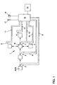
- the operating device has a spring-loaded switch 1, which is movable in six positions relative to a switch body (not shown) Contacts 2, 3 assigned to the operating functions of the cruise control system 4, 5, 6 open and close.
- the six positions of switch 1 are through Rectangles shown.
- Cruise control system switched off. In this position the switch is through a locking mechanism (not shown) secured against unwanted movement.
- the system is switched on by moving the switch to the right. in the The spring-loaded switch is normally in the operational state position marked with N. By moving the switch from the neutral position N the desired driving speed can be increased. By moving the switch from the neutral position N down can be the desired one Driving speed can be reduced accordingly.
- the Cruise control system switched off automatically.
- the previously set Driving speed is, however, saved and can be adjusted by moving the Switch 1 can be reactivated from the neutral position N to the extreme right position (Resume function).
- the cruise control can be temporarily switched off without the set travel speed being deleted ( Tip-off "function). If the driver releases switch 1 again, he automatically returns to neutral position N due to the spring load.
- the neutral position N is also a contact 7 assigned.
- the signal lines 8, 9, 10, 11, 12, 13 assigned to the contacts 2 to 7 are each connected to a signal detection and evaluation device 14.
- the Signal acquisition and evaluation device 14 is provided with a logic circuit which with simultaneous application of a signal assigned to the neutral position N and one a control function assigned signal the control function in question locks.
- the signal acquisition and evaluation device 14 the cruise control system automatically switches off if it has not been used for a certain period of time various positions of the switch 1 associated signals detected.
- the Logic circuit of the signal detection and evaluation device 14 is for this purpose with a Equipped timer.
- the signal detection and Evaluation device 14 To alert the driver to a possible electrical fault on one of the contacts 2 to 7 to make the switch 1 aware is the signal detection and Evaluation device 14 also with a warning light 16 and a buzzer 17 connected.
- FIGS. 2 to 12 show a further embodiment of an inventive Operating device.
- the device has a switch 18 with a contact unit 19 on, which can be moved in six positions and one in the respective position first, second, third and fourth signal lines 20, 21, 22, 23 with one at the Power supply of the motor vehicle connected feed line 24 connects.
- the neutral position of the switch 18 is established via the first signal line 20 assigned signal, whereas via the second, third or fourth Signal line 21, 22, 23, the operating signals are transmitted.
- the signal assigned to the neutral position is simple from a positive signal, i.e. an existing signal.
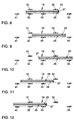
- the contact unit 19 of the Switch 18 has two conductor elements 25, 26, which are separated by a plastic layer 27 or the like are electrically insulated from one another (cf. FIGS. 8 to 12).
- the signal lines 20, 21, 22, 23 lead to a signal detection and Evaluation device 28 through a wiring harness 29 with a control device (not shown) of the cruise control system is connected.
- the control device gives in a known manner to the control system of the engine signals for regulating the Drive power and thus the speed of the vehicle.
- the switch 18 is in its neutral position. In this Position connects the upper conductor element 25 of the contact unit 19 to the Feed line 24 connected contact part 30 with a on the first signal line 20 connected contact part 31.
- the lower conductor element 26 of the contact unit 19 remains connected to the contact part 32 connected to the second signal line 21 and also arrives with a contact part 34 connected to the third signal line 22 and another the feed line 24 connected contact part 35 in connection.
- a signal is accordingly transmitted from the feed line 24 via the second and third signal lines 21, 22 to the signal detection and evaluation device 28 and the control device of the cruise control system.
- This signal which is preferably the TIP-OFF "function is assigned, assigns the three-digit code 1 1 0 ".
- the switch 18 If the switch 18 is moved further to the left into the position shown in FIG. 4, the lower conductor element 26 of the contact unit 19 comes into connection with a further contact part 36 which is connected to the fourth signal line 23. In the position shown in FIG. 4, this results in a signal whose three-digit code 1 1 1 ".
- the speed control system is preferably switched off by this signal, the switch 18 being secured against unwanted movement in this position by a latching device (not shown).
- the switch 18 is moved into the position shown in FIG. 6.
- the lower conductor element 26 of the contact unit 19 remains connected to the contact element 33 connected to the fourth signal line 23 and comes into connection with a further contact part 39 connected to the feed line 24 via a branch 38.
- the signal assigned to the acceleration function thus has the code 0 0 1 ".
- the upper conductor element 25 of the contact unit 19 is only connected to the contact part 30, which is likewise connected to the feed line 24 via a branch 40, as shown in FIG. 10. Accordingly, the switch position corresponding to the neutral position lies in this position Signal not on.
- the switch must be moved to the position shown in FIGS. 7 and 12.
- the lower conductor element 26 of the contact unit 19 remains connected to the contact element 32 connected to the second signal line and to the contact element 33 connected to the fourth signal line and additionally comes with another connected to the feed line 24 Contact part 41 in connection.
- the signal assigned to the delay function thus has the code 1 0 1 ".
- the upper conductor element 25 of the contact unit 19 in this position is only connected to the contact element 31 connected to the first signal line, so that the signal corresponding to the neutral position is again not present
- the signal of the neutral position is not present when the switch 18 is shifted from the neutral position to the left in the positions shown in FIGS. 3 and 4 or to the right in the position shown in FIG. 5, since the upper conductor element 25 the contact unit 19 in these positions is neither connected to the contact part 30 connected to the feed line 24 via the branch 40 nor to the contact part 31 connected to the first signal line 20.
- the contact unit 19 of the switch 18 is spring-loaded, so that after it is done Actuation of the switch 18 from the switch positions shown in FIGS. 3, 5, 6 and 7 automatically returns to neutral.
- the conductor elements 25, 26 of the contact unit 19 and those on the feed line 24 and the Signal lines 20, 21, 22, 23 connected contact elements 30, 35, 37, 39, 41 and 31, 32, 33, 34, 36 are designed such that when the switch 18 is moved his respective positions no unwanted functions of the Cruise control system can be activated. Accordingly, this surpasses the third signal line 22 connected contact element 34 that on the feed line 24 connected contact element 35, so that the lower conductor element 26 of the Contact unit 19 when moving to the position shown in Fig. 3 first with the on the third signal line 22 connected contact element 34 and only then the contact element 35 connected to the feed line 24 comes into connection. This rules out that one of the switch positions shown in FIG. 5 corresponding signal is emitted when the switch 18 is shifted to the left.
Landscapes
- Engineering & Computer Science (AREA)
- Chemical & Material Sciences (AREA)
- Combustion & Propulsion (AREA)
- Transportation (AREA)
- Mechanical Engineering (AREA)
- Controls For Constant Speed Travelling (AREA)
- Control Of Position Or Direction (AREA)
Abstract
Description

- Figur 1
- ein schematisches Blockschaltbild einer erfindungsgemäßen Bedienungsvorrichtung mit einem in sechs Stellungen bewegbaren Schalter;
- Figuren 2 bis 7
- jeweils Draufsichten auf ein zweites Ausführungsbeispiel einer erfindungsgemäßen Bedienungsvorrichtung in schematischer Darstellung mit einem in sechs Stellungen bewegbaren Schalter, und
- Figuren 8 bis 12
- jeweils schematische Schnittansichten des Schalters gemäß den Figuren 2 bis 7, und zwar in dessen Neutralstellung, der der Fahrzeugbeschleunigung entsprechenden Schaltstellung (Fig. 10), der der Verzögerung entsprechenden Schaltstellung (Fig. 12) sowie zwei Zwischenstellungen (Fig. 9 bzw. 11).
Claims (4)
- Bedienungsvorrichtung für eine Geschwindigkeitsregelanlage eines Kraftfahrzeuges, mit einem Schalter (1), der relativ zu einem Schalterkörper in mehrere Stellungen, insbesondere eine Neutralstellung bewegbar ist, um verschiedenen Bedienungsfunktionen zugeordnete Kontakte innerhalb des Schalters (1) zu öffnen und zu schließen,
dadurch gekennzeichnet, daß
der Neutralstellung (N) ebenfalls mindestens ein Kontakt (7) zugeordnet ist und eine Signalerfassungs- und Auswerteeinrichtung (14) vorhanden ist, an der den Kontakten (2, 3, 4, 5, 6, 7) zugeordnete Signalleitungen (8, 9, 10, 11, 12, 13) angeschlossen sind, wobei die Signalerfassungs- und Auswerteeinrichtung (14) eine Logikschaltung aufweist, die bei gleichzeitigem Anliegen eines der Neutralstellung (N) zugeordneten Signals und eines einer Bedienungsfunktion zugeordneten Signals die Ausführung einer der Bedienungsfunktionen verhindert. - Bedienungsvorrichtung nach Anspruch 1,
dadurch gekennzeichnet, daß
die Signalerfassungs- und Auswerteeinrichtung (14) die Geschwindigkeitsregelanlage automatisch ausschaltet, wenn sie über eine bestimmte Zeitdauer keines der den verschiedenen Stellungen des Schalters (1) zugeordneten Signale erfaßt. - Bedienungsvorrichtung nach Anspruch 1 oder 2,
dadurch gekennzeichnet, daß die Signalerfassungs- und Auswerteeinrichtung (14) beim Auftreten eines elektrischen Fehlers an einem der Kontakte des Schalters (1) eine optische Meldung bewirkt. - Bedienungsvorrichtung nach einem der vorstehenden Ansprüche,
dadurch gekennzeichnet, daß
der Schalter (1) in sechs Stellungen bewegbar ist.
Applications Claiming Priority (2)
| Application Number | Priority Date | Filing Date | Title |
|---|---|---|---|
| DE1999112726 DE19912726A1 (de) | 1999-03-20 | 1999-03-20 | Bedienungsvorrichtung für eine Geschwindigkeitsregelanlage |
| DE19912726 | 1999-03-20 |
Publications (2)
| Publication Number | Publication Date |
|---|---|
| EP1038721A2 true EP1038721A2 (de) | 2000-09-27 |
| EP1038721A3 EP1038721A3 (de) | 2001-09-12 |
Family
ID=7901861
Family Applications (1)
| Application Number | Title | Priority Date | Filing Date |
|---|---|---|---|
| EP00104414A Withdrawn EP1038721A3 (de) | 1999-03-20 | 2000-03-02 | Bedienungsvorrichtung für eine Geschwindigkeitsregelanlage |
Country Status (2)
| Country | Link |
|---|---|
| EP (1) | EP1038721A3 (de) |
| DE (1) | DE19912726A1 (de) |
Citations (3)
| Publication number | Priority date | Publication date | Assignee | Title |
|---|---|---|---|---|
| EP0428338A2 (de) * | 1989-11-16 | 1991-05-22 | Lucas Industries Public Limited Company | Geber-Überwachungs-Gerät und Verfahren |
| WO1994022687A1 (en) | 1993-04-07 | 1994-10-13 | Saab Automobile Aktiebolag | Arrangement for a cruise control system for a motor vehicle |
| DE19645561A1 (de) | 1996-11-05 | 1998-05-07 | Scania Cv Ab | Schalter für eine Geschwindigkeitsregelanlage |
Family Cites Families (7)
| Publication number | Priority date | Publication date | Assignee | Title |
|---|---|---|---|---|
| US2661071A (en) * | 1950-06-30 | 1953-12-01 | Hoener Lavern George | Motor vehicle speed control |
| JPS5699518A (en) * | 1980-01-14 | 1981-08-10 | Nissan Motor Co Ltd | Automatic constant-speed running device for car |
| JPS56101039A (en) * | 1980-01-18 | 1981-08-13 | Nissan Motor Co Ltd | Automatic system for operating vehicle at constant speed |
| US5128869A (en) * | 1987-12-25 | 1992-07-07 | Mitsubishi Jidosha Kogyo Kabushiki Kaisha | Engine controlling system for vehicle |
| DE4338098C2 (de) * | 1993-11-08 | 1996-09-05 | Daimler Benz Ag | Bedienhebel für eine Geschwindigkeitsregelanlage eines Kraftfahrzeuges |
| DE19537273A1 (de) * | 1995-10-06 | 1997-04-10 | Zahnradfabrik Friedrichshafen | Einrichtung zur Geschwindigkeitsregelung von Fahrzeugen |
| SE9700456L (sv) * | 1997-02-11 | 1998-02-02 | Scania Cv Ab | Anordning för att styra drivningen av ett fordon |
-
1999
- 1999-03-20 DE DE1999112726 patent/DE19912726A1/de not_active Ceased
-
2000
- 2000-03-02 EP EP00104414A patent/EP1038721A3/de not_active Withdrawn
Patent Citations (3)
| Publication number | Priority date | Publication date | Assignee | Title |
|---|---|---|---|---|
| EP0428338A2 (de) * | 1989-11-16 | 1991-05-22 | Lucas Industries Public Limited Company | Geber-Überwachungs-Gerät und Verfahren |
| WO1994022687A1 (en) | 1993-04-07 | 1994-10-13 | Saab Automobile Aktiebolag | Arrangement for a cruise control system for a motor vehicle |
| DE19645561A1 (de) | 1996-11-05 | 1998-05-07 | Scania Cv Ab | Schalter für eine Geschwindigkeitsregelanlage |
Also Published As
| Publication number | Publication date |
|---|---|
| EP1038721A3 (de) | 2001-09-12 |
| DE19912726A1 (de) | 2000-09-21 |
Similar Documents
| Publication | Publication Date | Title |
|---|---|---|
| DE4426207C1 (de) | Wähleinrichtung für ein Automatikgetriebe eines Kraftfahrzeugs | |
| DE3834390C1 (de) | ||
| EP0972667B1 (de) | Kraftfahrzeug mit einem elektronisch gesteuerten Automatikgetriebe und einer fremdkraftbetätigten Feststellbremse | |
| DE102012113126B4 (de) | Elektronische Schaltvorrichtung eines Fahrzeugs | |
| DE3203702A1 (de) | Betaetigungsvorrichtung fuer ein automatisches kraftfahrzeug-getriebe | |
| EP0128478A1 (de) | Regelsystem zur Sperrung eines Ausgleichsgetriebes | |
| EP0060326A2 (de) | Schutz- und Überwachungseinrichtung für Steuerschaltungsanordnungen in Kraftfahrzeugen | |
| EP0825364A2 (de) | Wähleinrichtung für ein Automatikgetriebe eines Kraftfahrzeugs | |
| DE2721879C3 (de) | Schalteinrichtung zum Ansteuern der Blinklampen in Kraftfahrzeugen | |
| DE10119212B4 (de) | Vorrichtung und Verfahren für einen Zündschalterstatus | |
| DE102021133205A1 (de) | Kraftfahrzeugschließeinrichtung | |
| DE2928194C2 (de) | Weichenantrieb | |
| EP1283139B1 (de) | Energieversorgungseinrichtung für bordnetzgestützte, sicherheitsrelevante Systemkomponenten von Fahrzeugen | |
| DE10393280B4 (de) | Getriebevorrichtung und Verfahren zum Betreiben einer Getriebevorrichtung | |
| EP1330868B1 (de) | Schaltungsanordnung mit einem zwei anschlüsse aufweisenden elektromotor | |
| DE19912726A1 (de) | Bedienungsvorrichtung für eine Geschwindigkeitsregelanlage | |
| DE19918566B4 (de) | Blinkerhebelvorrichtung | |
| EP1447830B1 (de) | Schaltvorrichtung zur codierung unterschiedlicher Schaltzustände | |
| DE4327455A1 (de) | System zur Ansteuerung eines Stellgliedes zur Einstellung der Luftzufuhr eines Kraftfahrzeugmotors | |
| EP1050698B1 (de) | Drucktastenwähleinrichtung für automatisches Getriebe | |
| DE4234261C2 (de) | Türverriegelungseinrichtung für Kraftfahrzeuge | |
| EP0978401B1 (de) | Vorrichtung zum Verstellen von bewegbaren Teilen an Fahrzeugen mittels eines kurzschliessbaren Stellmotors | |
| DE3019820C2 (de) | Schaltung für verschiedene Betriebszustände eines Magnetbandgerätes | |
| DE102014017716B4 (de) | Arbeitsmaschine | |
| DE19645561A1 (de) | Schalter für eine Geschwindigkeitsregelanlage |
Legal Events
| Date | Code | Title | Description |
|---|---|---|---|
| PUAI | Public reference made under article 153(3) epc to a published international application that has entered the european phase |
Free format text: ORIGINAL CODE: 0009012 |
|
| AK | Designated contracting states |
Kind code of ref document: A2 Designated state(s): AT BE CH CY DE DK ES FI FR GB GR IE IT LI LU MC NL PT SE |
|
| AX | Request for extension of the european patent |
Free format text: AL;LT;LV;MK;RO;SI |
|
| PUAL | Search report despatched |
Free format text: ORIGINAL CODE: 0009013 |
|
| AK | Designated contracting states |
Kind code of ref document: A3 Designated state(s): AT BE CH CY DE DK ES FI FR GB GR IE IT LI LU MC NL PT SE |
|
| AX | Request for extension of the european patent |
Free format text: AL;LT;LV;MK;RO;SI |
|
| 17P | Request for examination filed |
Effective date: 20020312 |
|
| AKX | Designation fees paid |
Free format text: AT BE CH CY DE DK ES FI FR GB GR IE IT LI LU MC NL PT SE |
|
| 17Q | First examination report despatched |
Effective date: 20030521 |
|
| GRAP | Despatch of communication of intention to grant a patent |
Free format text: ORIGINAL CODE: EPIDOSNIGR1 |
|
| STAA | Information on the status of an ep patent application or granted ep patent |
Free format text: STATUS: THE APPLICATION IS DEEMED TO BE WITHDRAWN |
|
| 18D | Application deemed to be withdrawn |
Effective date: 20041029 |