EP1038633A1 - Ensemble d'usinage de pièces par abrasif, notamment de superfinition - Google Patents
Ensemble d'usinage de pièces par abrasif, notamment de superfinition Download PDFInfo
- Publication number
- EP1038633A1 EP1038633A1 EP00400755A EP00400755A EP1038633A1 EP 1038633 A1 EP1038633 A1 EP 1038633A1 EP 00400755 A EP00400755 A EP 00400755A EP 00400755 A EP00400755 A EP 00400755A EP 1038633 A1 EP1038633 A1 EP 1038633A1
- Authority
- EP
- European Patent Office
- Prior art keywords
- abrasive
- oscillation
- advance
- pressure
- head
- Prior art date
- Legal status (The legal status is an assumption and is not a legal conclusion. Google has not performed a legal analysis and makes no representation as to the accuracy of the status listed.)
- Granted
Links
Images


Classifications
-
- B—PERFORMING OPERATIONS; TRANSPORTING
- B24—GRINDING; POLISHING
- B24B—MACHINES, DEVICES, OR PROCESSES FOR GRINDING OR POLISHING; DRESSING OR CONDITIONING OF ABRADING SURFACES; FEEDING OF GRINDING, POLISHING, OR LAPPING AGENTS
- B24B35/00—Machines or devices designed for superfinishing surfaces on work, i.e. by means of abrading blocks reciprocating with high frequency
-
- B—PERFORMING OPERATIONS; TRANSPORTING
- B24—GRINDING; POLISHING
- B24B—MACHINES, DEVICES, OR PROCESSES FOR GRINDING OR POLISHING; DRESSING OR CONDITIONING OF ABRADING SURFACES; FEEDING OF GRINDING, POLISHING, OR LAPPING AGENTS
- B24B21/00—Machines or devices using grinding or polishing belts; Accessories therefor
-
- B—PERFORMING OPERATIONS; TRANSPORTING
- B24—GRINDING; POLISHING
- B24B—MACHINES, DEVICES, OR PROCESSES FOR GRINDING OR POLISHING; DRESSING OR CONDITIONING OF ABRADING SURFACES; FEEDING OF GRINDING, POLISHING, OR LAPPING AGENTS
- B24B47/00—Drives or gearings; Equipment therefor
- B24B47/10—Drives or gearings; Equipment therefor for rotating or reciprocating working-spindles carrying grinding wheels or workpieces
-
- B—PERFORMING OPERATIONS; TRANSPORTING
- B24—GRINDING; POLISHING
- B24B—MACHINES, DEVICES, OR PROCESSES FOR GRINDING OR POLISHING; DRESSING OR CONDITIONING OF ABRADING SURFACES; FEEDING OF GRINDING, POLISHING, OR LAPPING AGENTS
- B24B5/00—Machines or devices designed for grinding surfaces of revolution on work, including those which also grind adjacent plane surfaces; Accessories therefor
Definitions
- the present invention relates to a machining assembly for abrasive parts, in particular super-finishing, comprising a head application of abrasive against a workpiece, means of guiding, advancing and pressing the application head against the workpiece to be machined, as well as means for fixing the assembly to a support.
- These known units intended in particular for superfinishing of pieces of revolution constitute a unitary set comprising an abrasive belt application head, means for advancing and pushing of the application head, of the tape running means abrasive, as well as the drive and control means correspondents.
- the set includes a housing inside which the means of advance and pressure of the head are grouped together application as well as the drive and control means, this casing carrying on a lateral side means for its fixing on a support and bearing on the opposite side, the application head of abrasive and the reels of unwinding and reeling of the tape abrasive passing over the application head.
- this known unitary assembly is relatively large, therefore bulky, bulky, and heavy, therefore difficult to transport and also to be mounted, for example on a tower where the available space is often restricted.
- the abrasive application head is cantilevered relative to the means for fixing the assembly to the support and also with respect to the means of guidance, advance and head pressure, located inside the housing. This results in a lack of precision to which even an oversizing resulting an increase in weight and cost would not bring than an imperfect solution.
- the present invention relates to a set for machining parts by abrasive which is distinguished by an architecture allowing both increase accuracy and decrease volume, therefore bulk and the weight of the assembly and, thereby, to simplify transport as well than mounting on a support.
- the set for machining parts by abrasive, in particular of superfinish, object of the invention includes an application head an abrasive against a workpiece, means for advancing and pressure of the abrasive application head against the workpiece and means for fixing the assembly to a support.
- the head application of abrasive and the means of advance and pressure of the head are aligned.
- the machining assembly can be very narrow, so that the overhang which may exist between the abrasive application head and the means of fixing the assembly on the support can be very reduced.
- the machining assembly according to the invention may have a particularly simple structure by the fact that the means of guide, advance and pressure of the application head include a fluid cylinder whose cylinder is integral with a feed guide which carries the fixing means and in which the piston rod of the jack is movable in axial translation while being immobilized angularly.
- the machining assembly further comprises in a manner known per se, means for oscillating the application head, to animate the latter with an oscillating movement perpendicular to the direction of advance and pressure.
- Said oscillation means include, between the piston rod of the jack feed and pressure and the abrasive application head, a guide and a swing rod mounted movable in translation axial in said oscillation guide while being immobilized angularly in the latter, a first of these elements, preferably the oscillation rod, being integral with the piston rod of the feed and pressure cylinder and the second element, preferably the oscillation guide, being integral with the abrasive application head of such that the axis of oscillation is perpendicular to the axis in advance and pressure.
- the set also includes means drive to animate one of the oscillation elements, preferably the oscillation guide, with a following oscillation movement its axis.
- the piston rod of the advance cylinder and pressure is hollow and crossed by an acting drive shaft by an eccentric system on the oscillation guide to animate this last of an oscillating movement.
- the piston rod of the advance and pressure cylinder is advantageously a square rod mounted movable in axial translation in a guide consisting of a square section socket.
- the combination of such a rod and such a socket which can also be chosen advantageously for the two elements of the means oscillation, automatically ensures the angular immobilization of the rod relative to the socket, and vice versa.
- the square section socket can be a bearing bush, in particular a ball bush.
- a bearing bush in particular a ball bush.
- Such sockets square ball bearings that provide high precision guidance, high load capacity and low friction, are well known and are marketed, for example, by the company TECHNOMETAL under the name "QUAD BALL BUSH".
- the machining assembly can be used either for machining by honing, with a bonded abrasive fixed at the application head, either for machining with an abrasive belt, at which case the machining assembly is completed by a scrolling system an abrasive belt during machining comprising a reel of new tape reel, a used tape reel, and a drive system in rotation of the resizing coil, the abrasive application head comprising a support roller which applies the abrasive strip against the workpiece.
- the coil of unwinding is advantageously mounted on the application head of abrasive so as to participate in the oscillation movement of this head.
- both the reel and the reel abrasive belt reels are movable in translation in the forward direction with the abrasive application head. This ensures the abrasive belt always constant tension, regardless of forward (and backward) movements of the application head.
- abrasive which groups the head application of abrasive, guiding, advancing and pressure means of this head and, where appropriate, the means of moving the strip abrasive, and a motorization and supply module which groups all drive motors and control means and power supply, the two modules being able to be coupled by means disconnectable flexible connection, namely flexible pipes for feeding the advance and thrust cylinder, a flexible shaft for the oscillation of the abrasive application head and, if necessary, a flexible shaft for running the abrasive belt.
- This dividion allows to obtain two relatively light modules, easy to transport, and the machining module, due to the absence of any means motorization incorporated, can be even more compact, therefore more easy to mount on a given support.
- an abrasive machining assembly in the occurrence of a set of superfinishing by abrasive belt to continuous scrolling, includes a machining module 1 and a motorization, control and supply 2.
- the two modules 1 and 2 are interconnected by flexible connecting means and disconnectable formed by two flexible pipes 3, a first flexible shaft 4 and a second flexible shaft 5.
- the module 2 shown in the form of a suitcase 6 with carrying handle 7 contains means for supplying pressurized fluid, not shown, a electric motor 8 as well as a gear motor 9.
- the machining module 1 comprises a guide 10 in the form of a square socket with balls serving as a guide for a rod 11 with a square external profile.
- the cylinder 12 of a fluid cylinder is connected to the rear end of the guide 10 or an intermediate piece 10a interposed between the cylinder 12 and the guide 10, the piston rod 13 of this cylinder being constituted by the rearward extension of the rod 11 mounted in the guide 10.
- the rod 11 is hollow and is crossed by a tree 14 which drives, at the front end of the rod 11, a eccentric system 15.
- the eccentric system 15 prints, under the effect of the rotation of the shaft 14, a linear oscillation movement to a guide 16 constituted by a square bushing with movable mounted balls in translation along an axis perpendicular to the axis of the rod 11, on a square rod 17 fixed by a yoke 18 to the front end of the rod 11.
- the guide 16 carries, by means of a yoke 19, a roller of pressure 20 whose function is to apply against a workpiece not shown, in particular a part of revolution driven in rotation around its axis, an abrasive belt 21 which is removed from a reel 22 and passes on the roller 20, under the movement of winding printed on a winding reel 23 by a reducer 24.
- both coils 22 and 23 are mounted, one at the front on the guide 16 by via a support 25 and the other at the rear on the rod 11 by through a support 26 so as to participate both translational movements produced by the cylinder 12, 13, the coil 22 also participating in the oscillation movement communicated to the pressure roller 20 by eccentric system 15.
- the unwinding reel 22 has a braking system 27 (see FIG. 6) by which the abrasive belt 21 always remains tensioned between the pay-out reel 22 and the take-up reel 23.
- Flexible hoses 3 going from module 2 to module 1 are used to supply fluid to the cylinder 12, 13.
- the flexible shaft 4 transmits the rotational movement of the motor 8 to the shaft 14, therefore to the eccentric system 15.
- the flexible shaft 5 transmits the movement of rotation of the gear motor 9 to the gear 24 used for the drive of the winding reel 23.
- the machining module 1 is fixed on a support, for example by fixing means 28 provided laterally on the guide 10or on the intermediate piece 10a, either on one side, as shown in thick solid lines in Figures 2, 4 and 5, or on the opposite side.
- the reducer 24 for the drive of the winding reel 23 can be arranged either on one side or the other of this coil, as shown in solid lines and in lines mixed in Figures 2 and 4.
- the machining module 1 has a remarkable architecture in particular by aligning the abrasive application head (roller pressure 20), guide means (guide 10, rod 11) and means advance and thrust (cylinder 12, 13), hence an absence of overhang between these elements and a very reduced overhang of the head applying abrasive (20) relative to the fixing means 28.
- the jack 12, 13 is sectioned circular could be replaced by one or two rectangular cylinders, of a type known per se, inserted directly between the guide 10 and the support 26 of the coil 23, these rectangular cylinders adapting better to the rectangular shape of the guide 10.
Landscapes
- Engineering & Computer Science (AREA)
- Mechanical Engineering (AREA)
- Finish Polishing, Edge Sharpening, And Grinding By Specific Grinding Devices (AREA)
- Polishing Bodies And Polishing Tools (AREA)
Abstract
Description
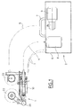
- la figure 1 est une vue d'ensemble schématique des deux modules d'un ensemble d'usinage à bande abrasive ;
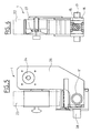
- la figure 2 est une vue de dessus du module d'usinage, sans les bobines de bande abrasive ;
- la figure 3 est une section longitudinale verticale schématique du module d'usinage à bande abrasive ;
- la figure 4 est une section transversale schématique du module d'usinage, au niveau de la bobine de renvidage de bande abrasive ;
- la figure 5 est une vue arrière du module d'usinage à bande abrasive ;
- la figure 6 est une section transversale schématique du module d'usinage à bande abrasive, au niveau de la bobine de dévidage de bande abrasive.
Claims (10)
- Ensemble d'usinage par abrasif de pièces, notamment de superfinition, comprenant une tête d'application de l'abrasif contre une pièce à usiner, des moyens de guidage, d'avance et de pression de la tête d'application contre la pièce à usiner et des moyens de fixation de l'ensemble sur un support, caractérisé par le fait que la tête d'application d'abrasif (19, 20) et les moyens de guidage, d'avance et de pression (10 à 14) de la tête sont alignés.
- Ensemble d'usinage suivant la revendication 1, caractérisé par le fait que les moyens de guidage, d'avance et de pression comprennent un vérin à fluide (12, 13) dont le cylindre (12) est solidaire d'un guide d'avance (10) qui porte les moyens de fixation (28) et dans lequel la tige de piston (11) du vérin est mobile en translation axiale en étant immobilisée angulairement.
- Ensemble suivant la revendication 2, comprenant en outre des moyens d'oscillation de la tête d'application d'abrasif, pour animer cette dernière d'un mouvement d'oscillation perpendiculairement à la direction d'avance et de pression, caractérisé par le fait que lesdits moyens d'oscillation comprennent, entre la tige de piston (11) du vérin d'avance et de pression (12, 13) et la tête d'application (19, 20), un guide d'oscillation (16) et une tige d'oscillation (17) montée mobile en translation axiale dans ledit guide d'oscillation en étant immobilisée angulairement dans ce dernier, un premier de ces éléments étant solidaire de la tige de piston du vérin d'avance et de pression et le second élément étant solidaire de la tête d'application d'abrasif de manière que l'axe d'oscillation soit perpendiculaire à l'axe d'avance et de pression, et que l'ensemble comprend, en outre, des moyens d'entraínement (14, 15) pour animer le second desdits éléments d'un mouvement d'oscillation suivant son axe.
- Ensemble suivant la revendication 3, caractérisé par le fait que la tige d'oscillation (17) est solidaire de la tige de piston (11) du vérin d'avance et de pression et que le guide d'oscillation (16) est solidaire de la tête d'application d'abrasif (19, 20).
- Ensemble suivant la revendication 4, caractérisé par le fait que la tige de piston (11) du vérin d'avance et de pression (12, 13) est creuse et travesée par un arbre d'entraínement (14) agissant par un système à excentrique sur le guide d'oscillation (16) pour animer ce dernier d'un mouvement d'oscillation.
- Ensemble d'usinage suivant l'une quelconque des revendications 3 à 5, caractérisé par le fait que la tige (11, 17) est une tige carrée montée mobile en translation dans une douille (10, 16) de section carrée.
- Ensemble suivant la revendication 6, caractérisé par le fait que la douille (10, 16) de section carrée est une douille à roulement, notamment une douille à billes.
- Ensemble suivant l'une quelconque des revendications précédentes, pour l'usinage par bande abrasive, avec un système de défilement d'une bande abrasive pendant l'usinage, comprenant une bobine de dévidage de bande neuve, une bobine de renvisage de bande usée et un système d'entraínement en rotation de la bobine de renvisage, la tête d'application d'abrasif comprenant un galet d'appui qui applique la bande abrasive contre la pièce à usiner, caractérisé par le fait que la bobine de dévidage (22) est montée sur la tête d'application d'abrasif (19, 20) de manière à participer au mouvement d'oscillation de cette tête.
- Ensemble suivant la revendication 8, caractérisé par le fait que la bobine de dévidage (22) et la bobine de renvidage (23) de la bande abrasive (21) sont montées mobiles en translation dans le sens d'avance avec la tête d'application d'abrasif (19, 20).
- Ensemble suivant l'une quelconque des revendications 2 à 9, caractérisé par le fait qu'il est divisé en un module d'usinage (1) qui comprend la tête d'application d'abrasif (19, 20), les moyens de guidage, d'avance et de pression (10 à 14) et, le cas échéant, le système de défilement de bande abrasive (22, 23, 24), et en un module de motorisation, d'alimentation et de commande (2) qui comprend les moteurs d'entraínement (8, 9) et les moyens de commande et d'alimentation, les deux modules (1, 2) pouvant être couplés par des moyens de liaison flexibles (3, 4, 5) déconnectables.
Applications Claiming Priority (2)
| Application Number | Priority Date | Filing Date | Title |
|---|---|---|---|
| FR9903604 | 1999-03-23 | ||
| FR9903604A FR2791292B1 (fr) | 1999-03-23 | 1999-03-23 | Ensemble d'usinage de pieces par abrasif, notamment de superfinition |
Publications (2)
| Publication Number | Publication Date |
|---|---|
| EP1038633A1 true EP1038633A1 (fr) | 2000-09-27 |
| EP1038633B1 EP1038633B1 (fr) | 2007-02-21 |
Family
ID=9543536
Family Applications (1)
| Application Number | Title | Priority Date | Filing Date |
|---|---|---|---|
| EP00400755A Expired - Lifetime EP1038633B1 (fr) | 1999-03-23 | 2000-03-17 | Ensemble d'usinage de pièces par abrasif, notamment de superfinition |
Country Status (5)
| Country | Link |
|---|---|
| EP (1) | EP1038633B1 (fr) |
| AT (1) | ATE354453T1 (fr) |
| DE (1) | DE60033459T2 (fr) |
| ES (1) | ES2278583T3 (fr) |
| FR (1) | FR2791292B1 (fr) |
Families Citing this family (1)
| Publication number | Priority date | Publication date | Assignee | Title |
|---|---|---|---|---|
| DE102011012337B4 (de) * | 2011-02-24 | 2013-01-24 | Thielenhaus Technologies Gmbh | Vorrichtung zum Bandfinishen |
Citations (2)
| Publication number | Priority date | Publication date | Assignee | Title |
|---|---|---|---|---|
| US4575972A (en) * | 1983-02-25 | 1986-03-18 | Kawasaki Seitetsu Kabushiki Kaisha | Grinding machine for use with rolling mill |
| FR2694902A1 (fr) * | 1992-08-18 | 1994-02-25 | Grieshaber Masch | Dispositif d'usinage de surfaces. |
Family Cites Families (1)
| Publication number | Priority date | Publication date | Assignee | Title |
|---|---|---|---|---|
| DE2320345A1 (de) * | 1973-04-21 | 1974-11-07 | Karl Heesemann | Bandschleifmaschine |
-
1999
- 1999-03-23 FR FR9903604A patent/FR2791292B1/fr not_active Expired - Fee Related
-
2000
- 2000-03-17 ES ES00400755T patent/ES2278583T3/es not_active Expired - Lifetime
- 2000-03-17 DE DE60033459T patent/DE60033459T2/de not_active Expired - Fee Related
- 2000-03-17 EP EP00400755A patent/EP1038633B1/fr not_active Expired - Lifetime
- 2000-03-17 AT AT00400755T patent/ATE354453T1/de not_active IP Right Cessation
Patent Citations (2)
| Publication number | Priority date | Publication date | Assignee | Title |
|---|---|---|---|---|
| US4575972A (en) * | 1983-02-25 | 1986-03-18 | Kawasaki Seitetsu Kabushiki Kaisha | Grinding machine for use with rolling mill |
| FR2694902A1 (fr) * | 1992-08-18 | 1994-02-25 | Grieshaber Masch | Dispositif d'usinage de surfaces. |
Also Published As
| Publication number | Publication date |
|---|---|
| FR2791292A1 (fr) | 2000-09-29 |
| ES2278583T3 (es) | 2007-08-16 |
| EP1038633B1 (fr) | 2007-02-21 |
| FR2791292B1 (fr) | 2001-04-27 |
| DE60033459D1 (de) | 2007-04-05 |
| DE60033459T2 (de) | 2007-10-31 |
| ATE354453T1 (de) | 2007-03-15 |
Similar Documents
| Publication | Publication Date | Title |
|---|---|---|
| EP0640435B1 (fr) | Machine à meuler | |
| FR2667530A1 (fr) | Procede et appareil de rectification des manetons de vilebrequin. | |
| EP0495691B1 (fr) | Machine d'usinage par abrasif de pièces cylindriques | |
| CA2354651A1 (fr) | Meuleuse de profils de rails | |
| EP0900171B1 (fr) | Dispositif tendeur de fil et materiel textile equipe d'un tel dispositif | |
| EP1957236B1 (fr) | Ensemble pour le poncage manuel d'une face d'une piece de caisse de vehicule | |
| EP1038633B1 (fr) | Ensemble d'usinage de pièces par abrasif, notamment de superfinition | |
| FR2471257A1 (fr) | Dispositif pour la rectification sans pointes de surfaces symetriques de revolution de pieces a travailler | |
| CA2452060C (fr) | Dispositif de transport de pieces pour l'alimentation de machines | |
| EP0624431A1 (fr) | Outillage pour l'application de toile abrasive sur une machine d'usinage par toilage de portées cylindriques sur des pièces | |
| EP0833711B1 (fr) | Dispositif pour positionner une broche d'usinage par sa tige pilote | |
| FR3027541A1 (fr) | Dispositif d'usinage vibratoire ameliore | |
| EP0434533B1 (fr) | Machine de superfinition pour des arbres, notamment des arbres à cames | |
| FR2464793A1 (fr) | Mecanisme d'ejection d'outil et machine equipes d'un tel mecanisme | |
| EP1336454A1 (fr) | Procédé et dispositif d'usinage par bande abrasive d'une surface de portée sur une pièce, notamment pour la superfinition d'une surface de came sur un arbre à cames | |
| FR2694715A1 (fr) | Procédé et appareil de rectification des manetons de villebrequin. | |
| EP0850722A1 (fr) | Machine d'usinage par bande abrasive de surfaces internes de pièces de révolution | |
| FR2584010A1 (fr) | Poupee porte-meule pivotante | |
| FR2473383A1 (fr) | Machine pour faire tourner coaxialement a elle-meme une piece de revolution, notamment a balourd | |
| WO2020035422A1 (fr) | Dispositif de percage orbital | |
| FR2509657A1 (fr) | Dispositif pour reduire le diametre de bois ronds | |
| FR2659879A1 (fr) | Dispositif de dressage d'un fil metallique. | |
| FR2523496A1 (fr) | Machine de rectification pour surfaces planes ou spheriques | |
| EP1125661B1 (fr) | Dispositif de perçage radial pour tour | |
| EP1129818A1 (fr) | Procédé de superfinition de pièces à surface cylindrique |
Legal Events
| Date | Code | Title | Description |
|---|---|---|---|
| PUAI | Public reference made under article 153(3) epc to a published international application that has entered the european phase |
Free format text: ORIGINAL CODE: 0009012 |
|
| AK | Designated contracting states |
Kind code of ref document: A1 Designated state(s): AT BE CH CY DE DK ES FI FR GB GR IE IT LI LU MC NL PT SE |
|
| AX | Request for extension of the european patent |
Free format text: AL;LT;LV;MK;RO;SI |
|
| 17P | Request for examination filed |
Effective date: 20010131 |
|
| AKX | Designation fees paid |
Free format text: AT BE CH CY DE DK ES FI FR GB GR IE IT LI LU MC NL PT SE |
|
| 17Q | First examination report despatched |
Effective date: 20011203 |
|
| RAP1 | Party data changed (applicant data changed or rights of an application transferred) |
Owner name: SPMS HONIMATIC |
|
| GRAP | Despatch of communication of intention to grant a patent |
Free format text: ORIGINAL CODE: EPIDOSNIGR1 |
|
| GRAS | Grant fee paid |
Free format text: ORIGINAL CODE: EPIDOSNIGR3 |
|
| GRAA | (expected) grant |
Free format text: ORIGINAL CODE: 0009210 |
|
| AK | Designated contracting states |
Kind code of ref document: B1 Designated state(s): AT BE CH CY DE DK ES FI FR GB GR IE IT LI LU MC NL PT SE |
|
| PG25 | Lapsed in a contracting state [announced via postgrant information from national office to epo] |
Ref country code: NL Free format text: LAPSE BECAUSE OF FAILURE TO SUBMIT A TRANSLATION OF THE DESCRIPTION OR TO PAY THE FEE WITHIN THE PRESCRIBED TIME-LIMIT Effective date: 20070221 Ref country code: IE Free format text: LAPSE BECAUSE OF FAILURE TO SUBMIT A TRANSLATION OF THE DESCRIPTION OR TO PAY THE FEE WITHIN THE PRESCRIBED TIME-LIMIT Effective date: 20070221 Ref country code: DK Free format text: LAPSE BECAUSE OF FAILURE TO SUBMIT A TRANSLATION OF THE DESCRIPTION OR TO PAY THE FEE WITHIN THE PRESCRIBED TIME-LIMIT Effective date: 20070221 Ref country code: FI Free format text: LAPSE BECAUSE OF FAILURE TO SUBMIT A TRANSLATION OF THE DESCRIPTION OR TO PAY THE FEE WITHIN THE PRESCRIBED TIME-LIMIT Effective date: 20070221 Ref country code: AT Free format text: LAPSE BECAUSE OF FAILURE TO SUBMIT A TRANSLATION OF THE DESCRIPTION OR TO PAY THE FEE WITHIN THE PRESCRIBED TIME-LIMIT Effective date: 20070221 |
|
| REG | Reference to a national code |
Ref country code: GB Ref legal event code: FG4D Free format text: NOT ENGLISH |
|
| GBT | Gb: translation of ep patent filed (gb section 77(6)(a)/1977) |
Effective date: 20070221 |
|
| REG | Reference to a national code |
Ref country code: CH Ref legal event code: EP |
|
| REF | Corresponds to: |
Ref document number: 60033459 Country of ref document: DE Date of ref document: 20070405 Kind code of ref document: P |
|
| PGFP | Annual fee paid to national office [announced via postgrant information from national office to epo] |
Ref country code: DE Payment date: 20070410 Year of fee payment: 8 |
|
| PGFP | Annual fee paid to national office [announced via postgrant information from national office to epo] |
Ref country code: ES Payment date: 20070418 Year of fee payment: 8 |
|
| REG | Reference to a national code |
Ref country code: IE Ref legal event code: FG4D Free format text: LANGUAGE OF EP DOCUMENT: FRENCH |
|
| PG25 | Lapsed in a contracting state [announced via postgrant information from national office to epo] |
Ref country code: SE Free format text: LAPSE BECAUSE OF FAILURE TO SUBMIT A TRANSLATION OF THE DESCRIPTION OR TO PAY THE FEE WITHIN THE PRESCRIBED TIME-LIMIT Effective date: 20070521 |
|
| PG25 | Lapsed in a contracting state [announced via postgrant information from national office to epo] |
Ref country code: PT Free format text: LAPSE BECAUSE OF FAILURE TO SUBMIT A TRANSLATION OF THE DESCRIPTION OR TO PAY THE FEE WITHIN THE PRESCRIBED TIME-LIMIT Effective date: 20070723 |
|
| NLV1 | Nl: lapsed or annulled due to failure to fulfill the requirements of art. 29p and 29m of the patents act | ||
| REG | Reference to a national code |
Ref country code: ES Ref legal event code: FG2A Ref document number: 2278583 Country of ref document: ES Kind code of ref document: T3 |
|
| REG | Reference to a national code |
Ref country code: IE Ref legal event code: FD4D |
|
| REG | Reference to a national code |
Ref country code: CH Ref legal event code: PL |
|
| PGFP | Annual fee paid to national office [announced via postgrant information from national office to epo] |
Ref country code: GB Payment date: 20070416 Year of fee payment: 8 |
|
| PLBE | No opposition filed within time limit |
Free format text: ORIGINAL CODE: 0009261 |
|
| STAA | Information on the status of an ep patent application or granted ep patent |
Free format text: STATUS: NO OPPOSITION FILED WITHIN TIME LIMIT |
|
| BERE | Be: lapsed |
Owner name: SPMS HONIMATIC Effective date: 20070331 |
|
| PG25 | Lapsed in a contracting state [announced via postgrant information from national office to epo] |
Ref country code: BE Free format text: LAPSE BECAUSE OF NON-PAYMENT OF DUE FEES Effective date: 20070331 |
|
| 26N | No opposition filed |
Effective date: 20071122 |
|
| PG25 | Lapsed in a contracting state [announced via postgrant information from national office to epo] |
Ref country code: MC Free format text: LAPSE BECAUSE OF NON-PAYMENT OF DUE FEES Effective date: 20070331 |
|
| PG25 | Lapsed in a contracting state [announced via postgrant information from national office to epo] |
Ref country code: LI Free format text: LAPSE BECAUSE OF NON-PAYMENT OF DUE FEES Effective date: 20070331 Ref country code: CH Free format text: LAPSE BECAUSE OF NON-PAYMENT OF DUE FEES Effective date: 20070331 |
|
| PG25 | Lapsed in a contracting state [announced via postgrant information from national office to epo] |
Ref country code: IT Free format text: LAPSE BECAUSE OF NON-PAYMENT OF DUE FEES Effective date: 20070317 Ref country code: GR Free format text: LAPSE BECAUSE OF FAILURE TO SUBMIT A TRANSLATION OF THE DESCRIPTION OR TO PAY THE FEE WITHIN THE PRESCRIBED TIME-LIMIT Effective date: 20070522 |
|
| PGFP | Annual fee paid to national office [announced via postgrant information from national office to epo] |
Ref country code: FR Payment date: 20070214 Year of fee payment: 8 |
|
| GBPC | Gb: european patent ceased through non-payment of renewal fee |
Effective date: 20080317 |
|
| REG | Reference to a national code |
Ref country code: FR Ref legal event code: ST Effective date: 20081125 |
|
| PG25 | Lapsed in a contracting state [announced via postgrant information from national office to epo] |
Ref country code: DE Free format text: LAPSE BECAUSE OF NON-PAYMENT OF DUE FEES Effective date: 20081001 |
|
| PG25 | Lapsed in a contracting state [announced via postgrant information from national office to epo] |
Ref country code: FR Free format text: LAPSE BECAUSE OF NON-PAYMENT OF DUE FEES Effective date: 20080331 |
|
| REG | Reference to a national code |
Ref country code: ES Ref legal event code: FD2A Effective date: 20080318 |
|
| PG25 | Lapsed in a contracting state [announced via postgrant information from national office to epo] |
Ref country code: GB Free format text: LAPSE BECAUSE OF NON-PAYMENT OF DUE FEES Effective date: 20080317 |
|
| PG25 | Lapsed in a contracting state [announced via postgrant information from national office to epo] |
Ref country code: CY Free format text: LAPSE BECAUSE OF FAILURE TO SUBMIT A TRANSLATION OF THE DESCRIPTION OR TO PAY THE FEE WITHIN THE PRESCRIBED TIME-LIMIT Effective date: 20070221 Ref country code: ES Free format text: LAPSE BECAUSE OF NON-PAYMENT OF DUE FEES Effective date: 20080318 |
|
| PG25 | Lapsed in a contracting state [announced via postgrant information from national office to epo] |
Ref country code: LU Free format text: LAPSE BECAUSE OF NON-PAYMENT OF DUE FEES Effective date: 20070317 |