EP1038164B1 - Transport detector with oxide surface coating - Google Patents
Transport detector with oxide surface coating Download PDFInfo
- Publication number
- EP1038164B1 EP1038164B1 EP98959020A EP98959020A EP1038164B1 EP 1038164 B1 EP1038164 B1 EP 1038164B1 EP 98959020 A EP98959020 A EP 98959020A EP 98959020 A EP98959020 A EP 98959020A EP 1038164 B1 EP1038164 B1 EP 1038164B1
- Authority
- EP
- European Patent Office
- Prior art keywords
- sample
- analytical apparatus
- conveying means
- analysing
- argon
- Prior art date
- Legal status (The legal status is an assumption and is not a legal conclusion. Google has not performed a legal analysis and makes no representation as to the accuracy of the status listed.)
- Expired - Lifetime
Links
- 239000011248 coating agent Substances 0.000 title claims description 6
- 238000000576 coating method Methods 0.000 title claims description 6
- RTAQQCXQSZGOHL-UHFFFAOYSA-N Titanium Chemical compound [Ti] RTAQQCXQSZGOHL-UHFFFAOYSA-N 0.000 claims abstract description 11
- 239000010936 titanium Substances 0.000 claims abstract description 8
- 229910052719 titanium Inorganic materials 0.000 claims abstract description 8
- XKRFYHLGVUSROY-UHFFFAOYSA-N Argon Chemical compound [Ar] XKRFYHLGVUSROY-UHFFFAOYSA-N 0.000 claims description 77
- 229910052786 argon Inorganic materials 0.000 claims description 39
- 238000000034 method Methods 0.000 claims description 27
- 238000000197 pyrolysis Methods 0.000 claims description 15
- 238000004458 analytical method Methods 0.000 claims description 14
- 239000002245 particle Substances 0.000 claims description 14
- XEEYBQQBJWHFJM-UHFFFAOYSA-N Iron Chemical compound [Fe] XEEYBQQBJWHFJM-UHFFFAOYSA-N 0.000 claims description 11
- 230000005264 electron capture Effects 0.000 claims description 11
- 239000002344 surface layer Substances 0.000 claims description 11
- 238000007789 sealing Methods 0.000 claims description 6
- 229910052742 iron Inorganic materials 0.000 claims description 5
- NINIDFKCEFEMDL-UHFFFAOYSA-N Sulfur Chemical compound [S] NINIDFKCEFEMDL-UHFFFAOYSA-N 0.000 claims description 3
- 239000005864 Sulphur Substances 0.000 claims description 3
- 239000004816 latex Substances 0.000 claims description 2
- 229920000126 latex Polymers 0.000 claims description 2
- 230000005591 charge neutralization Effects 0.000 claims 3
- OAICVXFJPJFONN-UHFFFAOYSA-N Phosphorus Chemical compound [P] OAICVXFJPJFONN-UHFFFAOYSA-N 0.000 claims 2
- 238000010521 absorption reaction Methods 0.000 claims 2
- 229910052698 phosphorus Inorganic materials 0.000 claims 2
- 239000011574 phosphorus Substances 0.000 claims 2
- 238000000151 deposition Methods 0.000 claims 1
- 239000002904 solvent Substances 0.000 description 18
- 239000007789 gas Substances 0.000 description 17
- 239000000203 mixture Substances 0.000 description 14
- 238000004587 chromatography analysis Methods 0.000 description 13
- 238000010438 heat treatment Methods 0.000 description 12
- 238000001514 detection method Methods 0.000 description 10
- 150000001875 compounds Chemical class 0.000 description 6
- 230000035945 sensitivity Effects 0.000 description 6
- 229910052695 Americium Inorganic materials 0.000 description 5
- PXHVJJICTQNCMI-UHFFFAOYSA-N Nickel Chemical compound [Ni] PXHVJJICTQNCMI-UHFFFAOYSA-N 0.000 description 5
- LXQXZNRPTYVCNG-UHFFFAOYSA-N americium atom Chemical compound [Am] LXQXZNRPTYVCNG-UHFFFAOYSA-N 0.000 description 5
- 238000001704 evaporation Methods 0.000 description 5
- 230000008020 evaporation Effects 0.000 description 5
- 239000000463 material Substances 0.000 description 5
- 230000008569 process Effects 0.000 description 5
- 230000002285 radioactive effect Effects 0.000 description 5
- CURLTUGMZLYLDI-UHFFFAOYSA-N Carbon dioxide Chemical compound O=C=O CURLTUGMZLYLDI-UHFFFAOYSA-N 0.000 description 4
- 239000000919 ceramic Substances 0.000 description 4
- 238000006243 chemical reaction Methods 0.000 description 4
- 238000009792 diffusion process Methods 0.000 description 4
- VNWKTOKETHGBQD-UHFFFAOYSA-N methane Chemical compound C VNWKTOKETHGBQD-UHFFFAOYSA-N 0.000 description 4
- 239000004810 polytetrafluoroethylene Substances 0.000 description 4
- 229920001343 polytetrafluoroethylene Polymers 0.000 description 4
- 239000000126 substance Substances 0.000 description 4
- IAZDPXIOMUYVGZ-UHFFFAOYSA-N Dimethylsulphoxide Chemical compound CS(C)=O IAZDPXIOMUYVGZ-UHFFFAOYSA-N 0.000 description 3
- 239000004696 Poly ether ether ketone Substances 0.000 description 3
- 238000010790 dilution Methods 0.000 description 3
- 239000012895 dilution Substances 0.000 description 3
- -1 ethanol and propanol Chemical class 0.000 description 3
- 230000006698 induction Effects 0.000 description 3
- 229910052751 metal Inorganic materials 0.000 description 3
- 239000002184 metal Substances 0.000 description 3
- 229910052756 noble gas Inorganic materials 0.000 description 3
- 229920002530 polyetherether ketone Polymers 0.000 description 3
- 239000007921 spray Substances 0.000 description 3
- 238000009736 wetting Methods 0.000 description 3
- LFQSCWFLJHTTHZ-UHFFFAOYSA-N Ethanol Chemical compound CCO LFQSCWFLJHTTHZ-UHFFFAOYSA-N 0.000 description 2
- 150000001298 alcohols Chemical class 0.000 description 2
- LBDSXVIYZYSRII-IGMARMGPSA-N alpha-particle Chemical compound [4He+2] LBDSXVIYZYSRII-IGMARMGPSA-N 0.000 description 2
- 125000003118 aryl group Chemical group 0.000 description 2
- 125000004429 atom Chemical group 0.000 description 2
- 239000001569 carbon dioxide Substances 0.000 description 2
- 229910002092 carbon dioxide Inorganic materials 0.000 description 2
- 239000000356 contaminant Substances 0.000 description 2
- 239000011521 glass Substances 0.000 description 2
- 239000011261 inert gas Substances 0.000 description 2
- 150000002500 ions Chemical class 0.000 description 2
- 239000010410 layer Substances 0.000 description 2
- 239000007788 liquid Substances 0.000 description 2
- 239000006249 magnetic particle Substances 0.000 description 2
- PXHVJJICTQNCMI-RNFDNDRNSA-N nickel-63 Chemical compound [63Ni] PXHVJJICTQNCMI-RNFDNDRNSA-N 0.000 description 2
- 239000002798 polar solvent Substances 0.000 description 2
- 239000000779 smoke Substances 0.000 description 2
- 239000010935 stainless steel Substances 0.000 description 2
- 229910001220 stainless steel Inorganic materials 0.000 description 2
- 238000000825 ultraviolet detection Methods 0.000 description 2
- 229910001369 Brass Inorganic materials 0.000 description 1
- RYGMFSIKBFXOCR-UHFFFAOYSA-N Copper Chemical compound [Cu] RYGMFSIKBFXOCR-UHFFFAOYSA-N 0.000 description 1
- UFHFLCQGNIYNRP-UHFFFAOYSA-N Hydrogen Chemical compound [H][H] UFHFLCQGNIYNRP-UHFFFAOYSA-N 0.000 description 1
- 239000003570 air Substances 0.000 description 1
- 150000001338 aliphatic hydrocarbons Chemical class 0.000 description 1
- 229910045601 alloy Inorganic materials 0.000 description 1
- 239000000956 alloy Substances 0.000 description 1
- 239000012080 ambient air Substances 0.000 description 1
- 239000003125 aqueous solvent Substances 0.000 description 1
- 238000001479 atomic absorption spectroscopy Methods 0.000 description 1
- 230000008901 benefit Effects 0.000 description 1
- 230000005250 beta ray Effects 0.000 description 1
- 239000010951 brass Substances 0.000 description 1
- 150000001720 carbohydrates Chemical class 0.000 description 1
- 235000014633 carbohydrates Nutrition 0.000 description 1
- 239000012159 carrier gas Substances 0.000 description 1
- 230000003197 catalytic effect Effects 0.000 description 1
- 230000008859 change Effects 0.000 description 1
- 229910052802 copper Inorganic materials 0.000 description 1
- 239000010949 copper Substances 0.000 description 1
- 239000003599 detergent Substances 0.000 description 1
- 238000010586 diagram Methods 0.000 description 1
- 239000006185 dispersion Substances 0.000 description 1
- 229920001971 elastomer Polymers 0.000 description 1
- 239000003480 eluent Substances 0.000 description 1
- 238000010828 elution Methods 0.000 description 1
- 239000003574 free electron Substances 0.000 description 1
- 238000004817 gas chromatography Methods 0.000 description 1
- 125000005843 halogen group Chemical group 0.000 description 1
- 229910052734 helium Inorganic materials 0.000 description 1
- 239000001307 helium Substances 0.000 description 1
- SWQJXJOGLNCZEY-UHFFFAOYSA-N helium atom Chemical compound [He] SWQJXJOGLNCZEY-UHFFFAOYSA-N 0.000 description 1
- 238000004128 high performance liquid chromatography Methods 0.000 description 1
- BHEPBYXIRTUNPN-UHFFFAOYSA-N hydridophosphorus(.) (triplet) Chemical compound [PH] BHEPBYXIRTUNPN-UHFFFAOYSA-N 0.000 description 1
- 229930195733 hydrocarbon Natural products 0.000 description 1
- 150000002430 hydrocarbons Chemical class 0.000 description 1
- 239000001257 hydrogen Substances 0.000 description 1
- 229910052739 hydrogen Inorganic materials 0.000 description 1
- 230000002209 hydrophobic effect Effects 0.000 description 1
- 230000006872 improvement Effects 0.000 description 1
- 238000011065 in-situ storage Methods 0.000 description 1
- 238000004255 ion exchange chromatography Methods 0.000 description 1
- 229910052743 krypton Inorganic materials 0.000 description 1
- DNNSSWSSYDEUBZ-UHFFFAOYSA-N krypton atom Chemical compound [Kr] DNNSSWSSYDEUBZ-UHFFFAOYSA-N 0.000 description 1
- 238000004093 laser heating Methods 0.000 description 1
- 238000005259 measurement Methods 0.000 description 1
- 230000007246 mechanism Effects 0.000 description 1
- 238000002844 melting Methods 0.000 description 1
- 230000008018 melting Effects 0.000 description 1
- 229910052754 neon Inorganic materials 0.000 description 1
- GKAOGPIIYCISHV-UHFFFAOYSA-N neon atom Chemical compound [Ne] GKAOGPIIYCISHV-UHFFFAOYSA-N 0.000 description 1
- 150000002835 noble gases Chemical class 0.000 description 1
- 230000003647 oxidation Effects 0.000 description 1
- 238000007254 oxidation reaction Methods 0.000 description 1
- 230000000704 physical effect Effects 0.000 description 1
- BDERNNFJNOPAEC-UHFFFAOYSA-N propan-1-ol Chemical compound CCCO BDERNNFJNOPAEC-UHFFFAOYSA-N 0.000 description 1
- 230000005855 radiation Effects 0.000 description 1
- 239000000941 radioactive substance Substances 0.000 description 1
- 238000001448 refractive index detection Methods 0.000 description 1
- 230000004044 response Effects 0.000 description 1
- 239000005060 rubber Substances 0.000 description 1
- 238000005070 sampling Methods 0.000 description 1
- 238000000926 separation method Methods 0.000 description 1
- 125000000547 substituted alkyl group Chemical group 0.000 description 1
- 235000000346 sugar Nutrition 0.000 description 1
- 150000008163 sugars Chemical class 0.000 description 1
- 238000001269 time-of-flight mass spectrometry Methods 0.000 description 1
- 230000000007 visual effect Effects 0.000 description 1
- 239000002699 waste material Substances 0.000 description 1
- XLYOFNOQVPJJNP-UHFFFAOYSA-N water Substances O XLYOFNOQVPJJNP-UHFFFAOYSA-N 0.000 description 1
Images


Classifications
-
- G—PHYSICS
- G01—MEASURING; TESTING
- G01N—INVESTIGATING OR ANALYSING MATERIALS BY DETERMINING THEIR CHEMICAL OR PHYSICAL PROPERTIES
- G01N30/00—Investigating or analysing materials by separation into components using adsorption, absorption or similar phenomena or using ion-exchange, e.g. chromatography or field flow fractionation
- G01N30/02—Column chromatography
- G01N30/84—Preparation of the fraction to be distributed
- G01N2030/8411—Intermediate storage of effluent, including condensation on surface
- G01N2030/8417—Intermediate storage of effluent, including condensation on surface the store moving as a whole, e.g. moving wire
-
- G—PHYSICS
- G01—MEASURING; TESTING
- G01N—INVESTIGATING OR ANALYSING MATERIALS BY DETERMINING THEIR CHEMICAL OR PHYSICAL PROPERTIES
- G01N30/00—Investigating or analysing materials by separation into components using adsorption, absorption or similar phenomena or using ion-exchange, e.g. chromatography or field flow fractionation
- G01N30/02—Column chromatography
- G01N30/62—Detectors specially adapted therefor
- G01N30/72—Mass spectrometers
- G01N30/728—Intermediate storage of effluent, including condensation on surface
- G01N30/7286—Intermediate storage of effluent, including condensation on surface the store moving as a whole, e.g. moving wire
Definitions
- the invention relates to a method of and apparatus for analysing a sample. and particularly to those comprising the use of conveying means to convey a sample to an analyser.
- UV detection has been found to be highly sensitive, accurate and simple to use.
- the compound to be analysed must absorb UV. This means that the technique cannot be used for several major classes of compounds, including carbohydrates, alcohols, detergents and aliphatic hydrocarbons. Also solvent choice is limited to U.V. transparent solvents.
- refractive index detection is used. Whilst it is a widely used method, it is less sensitive than the UV method described above and tends to be subject to considerable instability arising from eluent changes. It cannot be used with what is known in the art as Gradient Elution techniques.
- the components separated by chromatography are transported on a wire to a furnace where they are heated and pyrolysed.
- the pyrolysis products then pass by means of a complex set of conduits into an argon detector and are detected.
- the solute on the wire is burnt to carbon dioxide which is sucked into a hydrogen stream that passes over a nickel catalyst.
- the nickel catalyst converts the carbon dioxide quantitatively to methane which is detected by a flame ionisation detector (FID).
- FID flame ionisation detector
- the argon detector is concentration sensitive the dilution of pyrolysis produced in the carrier argon stream reduces the sensitivity.
- the FID is mass sensitive and not concentration sensitive dilution is not important but the dispersion of the peak in the conduit (peak broadening) and the high noise generated by the catalytic conversion significantly reduces the sensitivity.
- US-A-4178507 and DE-A-2732746 both disclose an analytical apparatus comprising a supply means, analying means and conveying means.
- the conveyer In the first of these the conveyer has an oxidised layer.
- An object of the present invention is to provide improved methods and apparatus for detecting components of a mixture which may have been separated by chromatography.
- an analytical apparatus comprising:
- the property may be a physical property, such as viscosity or melting temperature, of the sample or a chemical property, such as the chemical composition of the sample.
- the sample may be components of a mixture which has been previously separated by chromatography.
- the analysing means may be an analysing chamber, preferably without the need for conversion steps known hitherto.
- the oxidised surface layer is in the form of a continuous surface film.
- the oxidised surface layer may be porous.
- the oxidised surface layer is preferably readily wettable by solvents, especially aqueous and non-aqueous solvents such as water and polar solvents.
- solvents especially aqueous and non-aqueous solvents such as water and polar solvents.
- polar solvents include alcohols, such as ethanol and propanol, and DMSO.
- the oxidised surface layer is readily wettable by hydrocarbons including aromatic and non-aromatic, substituted and non-substituted alkyls.
- the sample is applied to the conveying means without substantial diffusion along the conveying means.
- the conveying means is a wire which has an oxidised surface layer.
- a tape of material or a disk of material may be used instead of the wire.
- the latter two forms of conveyor have an oxidised surface layer, and are less likely to break than wire. Tape is especially preferred.
- a typical width of tape is 1.5mm, with a thickness of 0.1mm.
- the conveying means is a wire or tape.
- the oxidised titanium forms a continuous porous surface film on the titanium metal and greatly enhances the carrying capabilities of the wire or tape.
- the oxidised wire wets very easily and will carry without difficulty both aqueous and non-aqueous liquids.
- Preoxidised titanium wire comprising an oxidised surface coating is commercially available, for example from Alloy Wire International, Cradley Heath, West Midlands, United Kingdom.
- the conveying means such as wire or tape is preferably carried on a supply spool and the invention may include drawing off the wire from the supply spool by means of a take up spool.
- a motor such as a stepper motor, may be computer controlled to draw the wire or tape at a desired rate from the supply spool.
- the invention preferably includes controlling the tension of the wire between the spools to maintain a substantially constant tension in the wire particularly when the wire is heated as set out below.
- a traverse mechanism may be provided to ensure that, for example, the tape/wire is regularly wound across the take up spool.
- the conveying means may be moved by means of one or more rollers in contact with the conveying means. This has the advantage that the speed of the conveying means does not vary according to the amount of e.g. tape/wire on the take up spool.
- the apparatus of the the invention includes an analyser chamber.
- a conveying means such as tape or wire
- wetting of the tape or wire with the separated components of the mixture can be improved by providing a polar cone opposite an aperture supplying the separated components of the mixture.
- the separated components of the mixture may be supplied to the surface of the tape or wire from an aperture in, for example, the end of a supply tube the end of which may be cone-shaped.
- the cone such as a titanium cone, comprising an oxidised surface coating, may be provided on the opposite side of the tape or wire with the tip of the cone directed towards the aperture.
- the cone draws off surplus mixture by directing the surplus mixture away from the tip of the cone, down the sides of the cone, to collection means.
- the oxidised layer on the surface of the cone improves the wettability of the cone and improves the ability of the cone to direct surplus mixture away from the wire or tape, thus preventing diffusion of the separated components along the wire or tape. Titanium is especially preferred as the material for the cone.
- the aperture and cone may be positioned so that a continuous stream of separated components joins the aperture to the cone, with the wire or tape passing through the stream.
- a strongly dispersive coating may be provided each side of the aperture providing the separated components. This prevents build up, by evaporation, of contaminants, which would ultimately contaminate the separated components, causing random noise.
- PTFE is especially preferred as the coating. This may be used in combination with the cone, described above.
- the conveyor such as wire or tape
- the conveyor may be subjected to heat prior to entry into the detection apparatus or analyser chamber to vaporise solvent from the component on the conveyor or wire.
- a nebuliser may be used to spray the sample onto the conveying means.
- the nebuliser is a heated nebuliser.
- the distance between the nebuliser and the surface of the conveying means may be adjusted so that at least some of any solvent with the sample evaporates before the sample contacts the surface of the conveying means. This allows the amount of diffusion of the sample on the conveying means to be controlled.
- the nebuliser comprises an inner tube through which the sample is passed.
- an outer tube through which a gas, such as air, is passed, and a nozzle where the gas and sample are combined and through which they are propelled.
- the outer tube may comprise heating means for preheating the gas and sample stream.
- Means for making the mixing of the gas and sample turbulent, thus improving the mixing may be provided.
- Such means include vanes for causing the gas to rotate prior to, or after, leaving the nozzle.
- the outside of the inner tube may be shaped, e.g. in the form of a helix, to rotate the gas flow.
- the component on the conveyer or wire may be subjected to pyrolysis to convert the component to a gas or sol such as smoke, the pyrolysis preferably taking place within or adjacent to the analyser chamber itself.
- the pyrolysis may be effected by heating coils disposed adjacent the conveyor or wire or by induction heating or by other means such as laser heating.
- the analyser chamber may be defined in a housing formed from a machineable glass or ceramic or from PTFE or PEEK (polyether ether ketone), or from a metal such as stainless steel, copper or brass.
- one or more gas chromatography detectors such as argon ionisation detectors, are used to detect the pyrolysed components given off by heating.
- Argon ionisation detectors are discussed in detail in the work by Scott R.P.W. et al, Chromatographic Detectors, Chromatographic Science Series, Vol.73, Marcel Dekker Inc. (New York), pages 119-147 (1996).
- the analyser chamber is preferably provided with a source of a noble gas, such as argon, an anode, a cathode, a potential between anode and cathode, and a radioactive source.
- the radioactive source may be an alpha-particle emitter, such as Americium, or a beta-particle emitter, such as Ni 63 .
- This form of sensor is very sensitive, and is universal in its response and does not have the sensitivity difficulties associated with using different solvents with other forms of sensor.
- a change in current flowing between the electrodes indicates the presence of separated components within the analysis chamber. This may be recorded for example graphically or on a computer.
- inert gases such as helium, neon or krypton. or a mixture thereof. may be used instead of argon.
- the invention may include providing further means for analysis downstream of the analyser chamber.
- the method of the invention is particularly advantageous in that respect as the pyrolysed sample is not further destroyed in the analyser chamber and can be passed for further analysis after the initial analysis has been completed.
- the further analysis may by performed by detectors such as Electron Capture, Phosphorous and Sulphur selective detectors, Atomic Absorption Spectroscopy and Time of Flight mass spectrometry.
- the argon ionisation detector may be omitted and one or more of the other detectors described above may be used instead.
- an electron capture detector downstream of a argon gas detector is especially preferred.
- Such detectors are discussed in the book by Scott R.P.W. (Supra).
- Such detectors operate on a different principle from that of argon detectors.
- a low energy ⁇ -ray source, such as Ni 63 is used to produce electrons as ions.
- Sensors can be made to function in a D.C. mode with a constant current applied across the sensor electrodes, or as pulsed mode, in which a pulsed potential is used.
- a constant electrode potential of a few volts is employed that is just sufficient to collect all the electrons that are produced and provide a small standing current. If an electron capturing molecule (for example a molecule containing a halogen atom with seven electrons in its outer shell) enters the sensor, the electrons are captured by the molecule and become charged. The mobility of the captured electrons are much reduced compared with free electrons and, furthermore, are likely to be neutralised by collision with any positive ions that are also generated. As a consequence, the electrode current falls dramatically.
- an electron capturing molecule for example a molecule containing a halogen atom with seven electrons in its outer shell
- a mixture of methane in argon is usually used as the carrier gas.
- the "off period" of the potential allows electrons to re-establish equilibrium with the gas resulting in improved sensitivity.
- Electron-capture detectors are extremely sensitive and are widely used in the analysis of halogenated compounds.
- an argon detector with an electron capture detector combines the universality of the argon detector with the specificity of the electron-capture detector in the same apparatus.
- the electron capture detector may be placed immediately downstream of the argon detector.
- means to neutralise the charge on the pyrolysed sample may be provided. This may be, for example, provided by means of an electron capture detector, for example, before the argon detector.
- pyrolysis is less suitable for some highly oxygenated compounds, such as sugars, which do not pyrolyse completely, but instead tend to form residues which remain on the conveyor.
- the high temperature which is required to completely pyrolyse such residues can ionise the pyrolysed compounds, resulting in difficulty in accurately detecting the compounds in, for example, argon detectors.
- the analysis chamber may be an argon detector comprising a source of noble gas, such as argon, an anode, a cathode, a potential between the anode and cathode, and a radioactive source.
- a source of noble gas such as argon
- an anode such as argon
- a cathode a potential between the anode and cathode
- a radioactive source such as argon
- the radioactive source is an alpha-particle emitter, such as Americium, or a beta-particle emitter such as Ni 63 .
- the separated components react with metastable argon in situ .
- the electrons emitted by the separated components are detected by the increase in current at the anode, as discussed previously.
- the argon gas once it has passed through the chamber, may be directed to an electron capture detector, and/or other detectors as discussed previously, for further analysis.
- the detectors used are extremely sensitive, hence, if the apparatus is not properly sealed, false readings may be produced from components in the surrounding atmosphere.
- Conventional seals of rubber, ceramic or metal surrounding the conveyor rapidly wear out, owing to the abrasive nature of the conveyor.
- the inventors have therefore developed an improved seal, comprising magnetisable particles of iron, iron coated with latex, or other commercially available magnetisable particles.
- the magnetisable particles are maintained in a sealing position by, for example, one or more iron or ceramic magnets or electro magnets.
- the magnetic field from the or each magnet keeps the magnetisable particles in a sealing position such as in the form of a "slug" of particles through which the conveyor passes.
- the particles are selected so that if any do escape into the analyser chamber(s), they are not detected or do not interfere with the analysis.
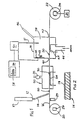
- a chromatography column 10 of known kind has its outlet 12 arranged adjacent the upper end of a feeder pipe 14.
- the feeder pipe 14 receives solvent from the chromatography column 10 containing a component separated from other components in the chromatography column 10.
- the lower end of the feeder pipe 14 is arranged immediately above a conveyor wire 16.
- the conveyor wire 16 is an oxidised titanium wire, the oxide forming a surface layer 18 as shown in Figure 2.
- the wire 16 is wound on a supply spool 20 and the wire is drawn from the spool 20 through the apparatus by means of a take-up spool 22.
- the take-up spool 22 is driven by a stepper motor 24 under the control of a computer 26.
- samples 30 of the separated components from the chromatography column are deposited sequentially at spaced-apart intervals on the wire 16.
- a device (not shown) may be provided for maintaining a constant tension in the wire 16.
- a heater 29 is arranged immediately downstream of the spool 20 which effectively oxidises and cleans the wire 16 before it reaches the outlet of the feeder pipe 14.
- the deposited component samples 30 From the outlet end of the feeder pipe 14, the deposited component samples 30 enter an evaporation station 32 where a heating device 34 such as heating coil or induction heating device is arranged. Solvent containing the separated components is evaporated at the evaporation station 32 to leave the component on the wire 16. A pump 35 is used to reduce the pressure the evaporation station 32 for drawing off the solvent vapour.
- a heating device 34 such as heating coil or induction heating device
- the wire passes through a detection unit 36 which defines an analyser chamber 38.
- the detection unit 36 is made, for example, from machineable glass or ceramic or from other suitable materials such as PTFE or PEEK.
- the detection unit 36 forms a housing having entry and exit ports 40, 42 for the wire 16, an inlet 44 for argon gas and an outlet 46.
- a heating device 48 such as a heating coil or an induction heating device is arranged in the chamber 38 immediately adjacent the wire 16.
- the detection unit housing carries electrodes 50, 51 and also carries a radioactive substance such as Americium which has an intrinsically safe level of radiation and which is readily available from a domestic smoke detector.
- the Americium 52 emits a particles into the chamber 38.
- Nickel-63 can be used as a ⁇ -emitter.
- the heating device 48 pyrolyses the sample 30 converting it to pyrolysis products within the chamber 38.
- the pyrolysis products mixes with the argon gas fed through the inlet 44, the argon being introduced at a pressure slightly higher than atmospheric pressure to exclude ambient air from entering the chamber 38 through the entry and exit ports 40,42.
- a typical flow rate of Argon of up to 50 ml/min, preferably 15-20 ml/min. is used.
- the detector unit 36 operates as described earlier to detect the pyrolysed components of sample 30 carried into the chamber 38 by the wire 16.
- the electrodes 50,51 of the detector are arranged in a detection circuit indicated generally at 54,
- the gas flow stream leaves the chamber 38 through the exit 46 and, from there, can be directed to further detectors if desired.
- the detection circuitry 54 responds to current flow between the electrodes 50.51 and provides an output signal to a visual display 56.
- the display 56 may produce a graphical representation 58 of the relative quantities of the various components of a substance passing through the chromatography column. It has been found that the method of detection is particularly sensitive bearing in mind that the component sample 30 passes through only a single conversion step for measurement purposes, the conversion step taking place within the analyser chamber 38 itself. Moreover, the pyrolysed component when mixed with the argon can be tested again after it leaves outlet 46 by other detectors. It is also possible to use only a single inert gas in the analyser chamber.
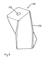
- FIG 3 shows a preferred arrangement of the feeder pipe 14 which supplies solvent from chromatography column 10.
- Pipe 14 delivers solvent containing the separated components in the direction of arrow 60.
- the pipe 14 is made of stainless steel.
- the solvent flows over wire 16 and forms a film 62.
- Excess solvent is directed away from the end of pipe 14 in the direction of flow lines 64 by the surface oxidised titanium cone 66.
- the oxidised surface of the cone 66 has been found to draw the excess solvent away efficiently, and to allow it to be drained off as waste 68. This produces improved distribution of solvent on the wire 16, with less diffusion of the film 62 than conventional systems.
- the solvent is a hydrophilic (polar) solvent
- a hydrophobic (dispersive) material such as PTFE
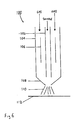
- Figure 4 shows an alternative embodiment of the invention.
- Wire 70 onto which sample 72 has been deposited, as previously described, passes into pyrolysis chamber 76 comprising heater 78 which may, if the sample is suitable, be used to pyrolyse sample 72.
- the wire 70 with the sample 72 is then drawn into the analyser chamber 80.
- the analyser chamber 80 comprises an ionising source 82, such as Nickel- 63 or Americium, and an anode and cathode 86.
- Argon is passed through the pyrolyser chamber 76 and analyser chamber 80 in the directions indicated by the arrows.
- the analysis chamber 80 therefore acts as an argon detector as discussed previously, the presence of a sample being detected by an increase in the current at the anode 84.
- the sample 72 is directly bombarded with metastable argon and electrons released are detected by an increase in current at the anode.
- the Figure also shows argon exiting the analysis chamber 80 and passing to further detectors for more detailed analysis (shown schematically as) boxes. Pyrolysis will be required if such a multi-detector option is used.
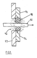
- Figure 5 shows a cross-section through a magnetic particle seal according to the invention.
- Wire 90 passes through aperture 92 in wall 93.
- Magnets 94, 96 provide a magnetic field (indicated by dotted lines) between north (N) and south (S) poles of the magnet.
- the magnetic field keeps a plug 98 of fine magnetisable particles, such as iron powder, around wire 90 and helps to prevent ingress of contaminants through the aperture 92.
- Figure 6 shows a nebuliser 100 comprising an inner tube 102 through which the sample to be analysed may be passed.
- An outer tube 104 around the inner tube 102 channels a supply of gas past heating elements 106 to a nozzle 108 where the sample and gas mix. This sprays the sample 110 onto a conveying means 112, such as wire or tape.
- Figure 7 shows a preferred arrangement of inner tube 102for causing the gas in the outer tube 104 to become turbulent.
- the inner tube 102 is shown to comprise an inner bore 120, through which the sample is passed, and an outer surface 122 which is twisted into a helix in order to rotate the supply of gas passing through the outer tube 104, prior to mixing with the sample. This improves the spray of the nebuliser.
- the apparatus has a very high sensitivity due to, for example, the use of the argon detector unit. Moreover, unlike some of the earlier detection methods, the present invention is useful for detecting substances which are impossible to detect with the earlier methods. Furthermore the apparatus may be fully automated and made smaller than conventional systems on the market.
Landscapes
- General Health & Medical Sciences (AREA)
- General Physics & Mathematics (AREA)
- Life Sciences & Earth Sciences (AREA)
- Chemical & Material Sciences (AREA)
- Analytical Chemistry (AREA)
- Biochemistry (AREA)
- Health & Medical Sciences (AREA)
- Immunology (AREA)
- Physics & Mathematics (AREA)
- Pathology (AREA)
- Sampling And Sample Adjustment (AREA)
- Other Investigation Or Analysis Of Materials By Electrical Means (AREA)
- Investigating Or Analysing Materials By Optical Means (AREA)
- Investigating Or Analyzing Non-Biological Materials By The Use Of Chemical Means (AREA)
- Treatment Of Liquids With Adsorbents In General (AREA)
Applications Claiming Priority (3)
| Application Number | Priority Date | Filing Date | Title |
|---|---|---|---|
| GB9726199 | 1997-12-12 | ||
| GBGB9726199.4A GB9726199D0 (en) | 1997-12-12 | 1997-12-12 | A method of and apparatus for detecting components of a mixture seperated by chromatography |
| PCT/GB1998/003672 WO1999031481A2 (en) | 1997-12-12 | 1998-12-10 | Transport detector with oxide surface coating |
Publications (2)
| Publication Number | Publication Date |
|---|---|
| EP1038164A2 EP1038164A2 (en) | 2000-09-27 |
| EP1038164B1 true EP1038164B1 (en) | 2003-05-21 |
Family
ID=10823452
Family Applications (1)
| Application Number | Title | Priority Date | Filing Date |
|---|---|---|---|
| EP98959020A Expired - Lifetime EP1038164B1 (en) | 1997-12-12 | 1998-12-10 | Transport detector with oxide surface coating |
Country Status (10)
| Country | Link |
|---|---|
| US (1) | US6462334B1 (enExample) |
| EP (1) | EP1038164B1 (enExample) |
| JP (1) | JP3626683B2 (enExample) |
| AT (1) | ATE241129T1 (enExample) |
| AU (1) | AU747241B2 (enExample) |
| CA (1) | CA2314135A1 (enExample) |
| DE (1) | DE69814916T2 (enExample) |
| ES (1) | ES2202913T3 (enExample) |
| GB (1) | GB9726199D0 (enExample) |
| WO (1) | WO1999031481A2 (enExample) |
Families Citing this family (9)
| Publication number | Priority date | Publication date | Assignee | Title |
|---|---|---|---|---|
| JP4174599B2 (ja) * | 2003-07-08 | 2008-11-05 | 株式会社島津製作所 | 高速液体クロマトグラフの分画装置 |
| JP4207782B2 (ja) * | 2004-01-06 | 2009-01-14 | 株式会社島津製作所 | 液体クロマトグラフの分画装置 |
| JP4148143B2 (ja) * | 2004-01-19 | 2008-09-10 | 株式会社島津製作所 | 液体クロマトグラフ等の分画装置 |
| WO2008070204A2 (en) * | 2006-06-09 | 2008-06-12 | Ion Applications, Inc. | Miniaturized ion mobility spectrometer |
| US8945351B2 (en) * | 2010-07-27 | 2015-02-03 | Heritage Environmental Services Llc | Induction heated gasifier |
| US8945350B2 (en) * | 2010-07-27 | 2015-02-03 | Heritage Environmental Services Llc | Induction heated screw |
| US8642953B2 (en) * | 2011-03-15 | 2014-02-04 | Lawrence Livermore National Security, Llc | Interface for the rapid analysis of liquid samples by accelerator mass spectrometry |
| US9051638B2 (en) * | 2013-03-01 | 2015-06-09 | Poole Ventura, Inc. | In-situ sputtering apparatus |
| EP2986704B1 (en) * | 2013-04-19 | 2019-04-03 | Siemens Healthcare Diagnostics Inc. | Non-contact micro droplet dispenser |
Family Cites Families (7)
| Publication number | Priority date | Publication date | Assignee | Title |
|---|---|---|---|---|
| US3128619A (en) * | 1961-03-24 | 1964-04-14 | Packard Instrument Co Inc | Method of and apparatus for monitoring for flowing stream content |
| US3566677A (en) * | 1969-06-26 | 1971-03-02 | Atomic Energy Commission | Method and apparatus for monitoring content of flowing streams |
| DE2654057B1 (de) * | 1976-11-29 | 1978-04-27 | Varian Mat Gmbh | Verfahren zur Ionisierung von organischen Substanzen,sowie dieses Verfahren benutzendes Analysegeraet |
| DE2732746A1 (de) * | 1977-07-20 | 1979-03-01 | Leybold Heraeus Gmbh & Co Kg | Verfahren und vorrichtung zur trennung und zum anschliessenden nachweis von substanzen |
| US4740298A (en) * | 1986-09-08 | 1988-04-26 | Sepragen Corporation | Chromatography column/moving belt interface |
| US5698358A (en) * | 1992-11-27 | 1997-12-16 | Xerox Corporation | Process for fabricating a belt with a seam having a curvilinear S shaped profile |
| US6132685A (en) * | 1998-08-10 | 2000-10-17 | Caliper Technologies Corporation | High throughput microfluidic systems and methods |
-
1997
- 1997-12-12 GB GBGB9726199.4A patent/GB9726199D0/en not_active Ceased
-
1998
- 1998-12-10 JP JP2000539331A patent/JP3626683B2/ja not_active Expired - Fee Related
- 1998-12-10 US US09/581,467 patent/US6462334B1/en not_active Expired - Fee Related
- 1998-12-10 EP EP98959020A patent/EP1038164B1/en not_active Expired - Lifetime
- 1998-12-10 CA CA002314135A patent/CA2314135A1/en not_active Abandoned
- 1998-12-10 AT AT98959020T patent/ATE241129T1/de not_active IP Right Cessation
- 1998-12-10 DE DE69814916T patent/DE69814916T2/de not_active Expired - Fee Related
- 1998-12-10 WO PCT/GB1998/003672 patent/WO1999031481A2/en not_active Ceased
- 1998-12-10 ES ES98959020T patent/ES2202913T3/es not_active Expired - Lifetime
- 1998-12-10 AU AU14958/99A patent/AU747241B2/en not_active Ceased
Also Published As
| Publication number | Publication date |
|---|---|
| AU1495899A (en) | 1999-07-05 |
| WO1999031481A3 (en) | 1999-09-16 |
| ES2202913T3 (es) | 2004-04-01 |
| CA2314135A1 (en) | 1999-06-24 |
| AU747241B2 (en) | 2002-05-09 |
| ATE241129T1 (de) | 2003-06-15 |
| DE69814916D1 (de) | 2003-06-26 |
| JP2003524752A (ja) | 2003-08-19 |
| EP1038164A2 (en) | 2000-09-27 |
| JP3626683B2 (ja) | 2005-03-09 |
| GB9726199D0 (en) | 1998-02-11 |
| US6462334B1 (en) | 2002-10-08 |
| DE69814916T2 (de) | 2004-01-29 |
| WO1999031481A2 (en) | 1999-06-24 |
Similar Documents
| Publication | Publication Date | Title |
|---|---|---|
| US9523657B2 (en) | Practical ion mobility spectrometer apparatus and methods for chemical and/or biological detection | |
| US8258468B2 (en) | Ion mobility spectrometer apparatus and methods | |
| US8653449B2 (en) | Sensitive ion detection device and method for analysis of compounds as vapors in gases | |
| Liu et al. | Advances in discharge-based microplasmas for the analysis of trace species by atomic spectrometry | |
| WO1993019481A1 (en) | Ion source and sample introduction method and apparatus | |
| EP1038164B1 (en) | Transport detector with oxide surface coating | |
| US5014009A (en) | Detector for gas chromatograph for detecting ammonia and amine compounds | |
| EP2435166A1 (en) | Direct atmospheric pressure sample analyzing system | |
| US10794862B2 (en) | Practical ion mobility spectrometer apparatus and methods for chemical and/or biological detection | |
| US10309929B2 (en) | Practical ion mobility spectrometer apparatus and methods for chemical and/or biological detection | |
| US10073056B2 (en) | Practical ion mobility spectrometer apparatus and methods for chemical and/or biological detection | |
| JP2006261116A (ja) | 複数のスプレーエミッタを備えているナノスプレーイオン源 | |
| JPH09507573A (ja) | 改良型パルス放電システム | |
| Broekaert et al. | Spectrochemical analysis with DC glow discharges at atmospheric pressure | |
| US6037179A (en) | Method and apparatus for suppression of analyte diffusion in an ionization detector | |
| US5521098A (en) | Thermionic ionization detector with flow-through thermionic source | |
| JP3819146B2 (ja) | モニタ装置 | |
| US5760291A (en) | Method and apparatus for mixing column effluent and make-up gas in an electron capture detector | |
| JPH0446379B2 (enExample) | ||
| JP2000028580A (ja) | 金属試料中の元素分析装置 | |
| US11460440B2 (en) | Practical ion mobility spectrometer apparatus and methods for chemical and/or biological detection | |
| JP2011252920A (ja) | Hplcを用いて材料特性を決定する装置および方法 | |
| JPH0453256B2 (enExample) | ||
| de Gois et al. | Electrothermal Vaporization Inductively Coupled Plasma Mass Spectrometry (ETV-ICP-MS) | |
| Vukanović et al. | Direct solution analysis using an arc source incorporating two plasmas rotating in a graphite tube |
Legal Events
| Date | Code | Title | Description |
|---|---|---|---|
| PUAI | Public reference made under article 153(3) epc to a published international application that has entered the european phase |
Free format text: ORIGINAL CODE: 0009012 |
|
| 17P | Request for examination filed |
Effective date: 20000616 |
|
| AK | Designated contracting states |
Kind code of ref document: A2 Designated state(s): AT BE CH DE ES FR GB IT LI NL SE |
|
| GRAH | Despatch of communication of intention to grant a patent |
Free format text: ORIGINAL CODE: EPIDOS IGRA |
|
| RIC1 | Information provided on ipc code assigned before grant |
Free format text: 7G 01N 1/00 A |
|
| GRAH | Despatch of communication of intention to grant a patent |
Free format text: ORIGINAL CODE: EPIDOS IGRA |
|
| GRAA | (expected) grant |
Free format text: ORIGINAL CODE: 0009210 |
|
| AK | Designated contracting states |
Designated state(s): AT BE CH DE ES FR GB IT LI NL SE |
|
| REG | Reference to a national code |
Ref country code: GB Ref legal event code: FG4D |
|
| REG | Reference to a national code |
Ref country code: CH Ref legal event code: EP |
|
| REF | Corresponds to: |
Ref document number: 69814916 Country of ref document: DE Date of ref document: 20030626 Kind code of ref document: P |
|
| REG | Reference to a national code |
Ref country code: SE Ref legal event code: TRGR |
|
| REG | Reference to a national code |
Ref country code: CH Ref legal event code: NV Representative=s name: ALTHOFF PATENTANWALTSBUERO |
|
| ET | Fr: translation filed | ||
| PLBE | No opposition filed within time limit |
Free format text: ORIGINAL CODE: 0009261 |
|
| STAA | Information on the status of an ep patent application or granted ep patent |
Free format text: STATUS: NO OPPOSITION FILED WITHIN TIME LIMIT |
|
| REG | Reference to a national code |
Ref country code: ES Ref legal event code: FG2A Ref document number: 2202913 Country of ref document: ES Kind code of ref document: T3 |
|
| 26N | No opposition filed |
Effective date: 20040224 |
|
| PGFP | Annual fee paid to national office [announced via postgrant information from national office to epo] |
Ref country code: GB Payment date: 20041203 Year of fee payment: 7 |
|
| PGFP | Annual fee paid to national office [announced via postgrant information from national office to epo] |
Ref country code: AT Payment date: 20041207 Year of fee payment: 7 |
|
| PGFP | Annual fee paid to national office [announced via postgrant information from national office to epo] |
Ref country code: ES Payment date: 20041214 Year of fee payment: 7 |
|
| PGFP | Annual fee paid to national office [announced via postgrant information from national office to epo] |
Ref country code: SE Payment date: 20041217 Year of fee payment: 7 |
|
| PGFP | Annual fee paid to national office [announced via postgrant information from national office to epo] |
Ref country code: CH Payment date: 20041220 Year of fee payment: 7 |
|
| PGFP | Annual fee paid to national office [announced via postgrant information from national office to epo] |
Ref country code: NL Payment date: 20041223 Year of fee payment: 7 |
|
| PGFP | Annual fee paid to national office [announced via postgrant information from national office to epo] |
Ref country code: FR Payment date: 20041230 Year of fee payment: 7 |
|
| PGFP | Annual fee paid to national office [announced via postgrant information from national office to epo] |
Ref country code: DE Payment date: 20041231 Year of fee payment: 7 |
|
| PGFP | Annual fee paid to national office [announced via postgrant information from national office to epo] |
Ref country code: BE Payment date: 20050113 Year of fee payment: 7 |
|
| PG25 | Lapsed in a contracting state [announced via postgrant information from national office to epo] |
Ref country code: IT Free format text: LAPSE BECAUSE OF NON-PAYMENT OF DUE FEES Effective date: 20051210 Ref country code: AT Free format text: LAPSE BECAUSE OF NON-PAYMENT OF DUE FEES Effective date: 20051210 |
|
| PG25 | Lapsed in a contracting state [announced via postgrant information from national office to epo] |
Ref country code: SE Free format text: LAPSE BECAUSE OF NON-PAYMENT OF DUE FEES Effective date: 20051211 |
|
| PG25 | Lapsed in a contracting state [announced via postgrant information from national office to epo] |
Ref country code: ES Free format text: LAPSE BECAUSE OF NON-PAYMENT OF DUE FEES Effective date: 20051212 |
|
| PG25 | Lapsed in a contracting state [announced via postgrant information from national office to epo] |
Ref country code: LI Free format text: LAPSE BECAUSE OF NON-PAYMENT OF DUE FEES Effective date: 20051231 Ref country code: CH Free format text: LAPSE BECAUSE OF NON-PAYMENT OF DUE FEES Effective date: 20051231 Ref country code: BE Free format text: LAPSE BECAUSE OF NON-PAYMENT OF DUE FEES Effective date: 20051231 |
|
| PG25 | Lapsed in a contracting state [announced via postgrant information from national office to epo] |
Ref country code: NL Free format text: LAPSE BECAUSE OF NON-PAYMENT OF DUE FEES Effective date: 20060701 Ref country code: DE Free format text: LAPSE BECAUSE OF NON-PAYMENT OF DUE FEES Effective date: 20060701 |
|
| REG | Reference to a national code |
Ref country code: CH Ref legal event code: PL |
|
| EUG | Se: european patent has lapsed | ||
| GBPC | Gb: european patent ceased through non-payment of renewal fee |
Effective date: 20051210 |
|
| PG25 | Lapsed in a contracting state [announced via postgrant information from national office to epo] |
Ref country code: FR Free format text: LAPSE BECAUSE OF NON-PAYMENT OF DUE FEES Effective date: 20060831 |
|
| NLV4 | Nl: lapsed or anulled due to non-payment of the annual fee |
Effective date: 20060701 |
|
| REG | Reference to a national code |
Ref country code: FR Ref legal event code: ST Effective date: 20060831 |
|
| REG | Reference to a national code |
Ref country code: ES Ref legal event code: FD2A Effective date: 20051212 |
|
| BERE | Be: lapsed |
Owner name: *SCIENTIFIC DETECTORS LTD Effective date: 20051231 |