EP1038074B1 - Verfahren zur herstellung eines fertigteils und fertigteil - Google Patents
Verfahren zur herstellung eines fertigteils und fertigteil Download PDFInfo
- Publication number
- EP1038074B1 EP1038074B1 EP98955629A EP98955629A EP1038074B1 EP 1038074 B1 EP1038074 B1 EP 1038074B1 EP 98955629 A EP98955629 A EP 98955629A EP 98955629 A EP98955629 A EP 98955629A EP 1038074 B1 EP1038074 B1 EP 1038074B1
- Authority
- EP
- European Patent Office
- Prior art keywords
- plate
- plates
- prefabricated member
- seal
- joint surfaces
- Prior art date
- Legal status (The legal status is an assumption and is not a legal conclusion. Google has not performed a legal analysis and makes no representation as to the accuracy of the status listed.)
- Expired - Lifetime
Links
Images


Classifications
-
- E—FIXED CONSTRUCTIONS
- E04—BUILDING
- E04C—STRUCTURAL ELEMENTS; BUILDING MATERIALS
- E04C2/00—Building elements of relatively thin form for the construction of parts of buildings, e.g. sheet materials, slabs, or panels
- E04C2/02—Building elements of relatively thin form for the construction of parts of buildings, e.g. sheet materials, slabs, or panels characterised by specified materials
- E04C2/26—Building elements of relatively thin form for the construction of parts of buildings, e.g. sheet materials, slabs, or panels characterised by specified materials composed of materials covered by two or more of groups E04C2/04, E04C2/08, E04C2/10 or of materials covered by one of these groups with a material not specified in one of the groups
- E04C2/284—Building elements of relatively thin form for the construction of parts of buildings, e.g. sheet materials, slabs, or panels characterised by specified materials composed of materials covered by two or more of groups E04C2/04, E04C2/08, E04C2/10 or of materials covered by one of these groups with a material not specified in one of the groups at least one of the materials being insulating
- E04C2/296—Building elements of relatively thin form for the construction of parts of buildings, e.g. sheet materials, slabs, or panels characterised by specified materials composed of materials covered by two or more of groups E04C2/04, E04C2/08, E04C2/10 or of materials covered by one of these groups with a material not specified in one of the groups at least one of the materials being insulating composed of insulating material and non-metallic or unspecified sheet-material
-
- B—PERFORMING OPERATIONS; TRANSPORTING
- B32—LAYERED PRODUCTS
- B32B—LAYERED PRODUCTS, i.e. PRODUCTS BUILT-UP OF STRATA OF FLAT OR NON-FLAT, e.g. CELLULAR OR HONEYCOMB, FORM
- B32B3/00—Layered products comprising a layer with external or internal discontinuities or unevennesses, or a layer of non-planar shape; Layered products comprising a layer having particular features of form
- B32B3/26—Layered products comprising a layer with external or internal discontinuities or unevennesses, or a layer of non-planar shape; Layered products comprising a layer having particular features of form characterised by a particular shape of the outline of the cross-section of a continuous layer; characterised by a layer with cavities or internal voids ; characterised by an apertured layer
- B32B3/30—Layered products comprising a layer with external or internal discontinuities or unevennesses, or a layer of non-planar shape; Layered products comprising a layer having particular features of form characterised by a particular shape of the outline of the cross-section of a continuous layer; characterised by a layer with cavities or internal voids ; characterised by an apertured layer characterised by a layer formed with recesses or projections, e.g. hollows, grooves, protuberances, ribs
-
- E—FIXED CONSTRUCTIONS
- E04—BUILDING
- E04C—STRUCTURAL ELEMENTS; BUILDING MATERIALS
- E04C2/00—Building elements of relatively thin form for the construction of parts of buildings, e.g. sheet materials, slabs, or panels
- E04C2/30—Building elements of relatively thin form for the construction of parts of buildings, e.g. sheet materials, slabs, or panels characterised by the shape or structure
- E04C2/32—Building elements of relatively thin form for the construction of parts of buildings, e.g. sheet materials, slabs, or panels characterised by the shape or structure formed of corrugated or otherwise indented sheet-like material; composed of such layers with or without layers of flat sheet-like material
- E04C2/328—Building elements of relatively thin form for the construction of parts of buildings, e.g. sheet materials, slabs, or panels characterised by the shape or structure formed of corrugated or otherwise indented sheet-like material; composed of such layers with or without layers of flat sheet-like material slightly bowed or folded panels not otherwise provided for
Definitions
- the invention relates to a prefabricated member as defined in the preamble of claim 1.
- the invention also relates to a method for producing a prefabricated member as defined in the preamble of claim 6.
- a prefabricated member which comprises a frame and a supporting battening, a core plate such as an insulating plate fitted into these, and surface plates attached, preferably by glueing, to both sides of this.
- a prefabricated member is manufactured e.g. by applying glue to the first surface plate, by placing the frame and the supporting battening first and subsequently the core plate against the glued surface of the surface plate, and a second surface plate, to which glue has been applied as well, is in turn fitted on the frame, the supporting battening and the core plate, with the glued surface facing the core plate. After this the surface plates, the frame, the supporting battening and the core plate are compressed by means of an appropriate press, the glue films between the plates being then also dried, thus providing a tight prefabricated member.
- the production method described above has the drawback of poor adherence between the parts of the prefabricated member. This is due to the large number of air bubbles and air pockets in the adhesive layer between the core plate and the surface plates, because air cannot escape from between the plates during compression.
- the production method described also has the drawback of emitting harmful glue vapours to the environment.
- the application of the method is restricted by the fact that it is difficult to manufacture tridimensional bodies by means of the method, because the compression direction is merely unidirectional.
- FI patent specification 66963 describes a prefabricated member, in which the core plate fitted in a framing and supporting structure is made of an air-permeable material, such as foam plastic, and an adhesive material which cures rapidly under the effect of moisture is used for fastening the surface plates and the core plates to one another.
- the prefabricated member is manufactured by absorbing air from the core plate, thus generating a vacuum in the core plate, so that the ambient atmospheric pressure presses the surface plates tightly to the framing and supporting structure and to the core plate. Nevertheless, this method does not enable prefabricated members to be manufactured from a hermetic and/or solid core plate.
- FI patent specification 94277 describes a method for manufacturing a prefabricated member.
- the prefabricated member comprises surface plates, a hermetic edge material and/or a mounting frame and a stationary intermediate material plate.
- the components of the prefabricated member are bonded by means of a vacuum.
- the stationary intermediate material plate is a plate with fluted surfaces.
- a suction opening communicating with the grooves has been provided in the mounting frame. The vacuum is generated through the suction opening and the grooves between the intermediate material plate and the surface plates, and the air bubbles and pockets are simultaneously removed from the glued surfaces.
- the ambient atmospheric pressure presses the surface plates into contact with the mounting frame and the intermediate material plate.
- the method for manufacturing a prefabricated member described above involves the problem of a great number of working steps. Accordingly, the prefabricated member will have the drawback of the large number of components required, especially the mounting frame or a similar component.
- the production method is also limited by the fact that the mounting frame sets limitations on the shape of the prefabricated member. In principle, it enables the manufacture of rectangular planear members alone.
- the object of the invention is to provide a new prefabricated member which has a more flexible and versatile shape than previously known prefabricated members have.
- Another object of this invention is to provide a new method for manufacturing a prefabricated member which allows the problems of conventional methods to be overcome and their restrictions to be eliminated.
- the prefabricated member of the invention comprises at least two plates, the first, i.e. core plate, and the second, i.e. surface plate, which are bonded by their joint surfaces equipped with a glue film, the first plate being provided at its joint surface with at least one array of interconnected grooves forming a fluted area, and the first plate comprising at least in the step of manufacturing the prefabricated member an opening for a vacuum, which opening communicates at one end with the grooves and at the other end with the outside of the plate.
- a seal having bond surfaces is provided around the fluted area formed by the grooves between the joint surfaces of the plates, the seal being provided for prefixing the joint surfaces of the plates to one another in order to provide an at least partly hermetic barrier around the fluted area at the stage of manufacturing the prefabricated member
- the prefabricated member of the invention has the advantage of a simpler structure compared with conventional prefabricated members.
- the prefabricated member of the invention has the further advantage of the surface plate or plates being tightly and firmly attached to the core plate.
- the prefabricated plate of the invention can be applied to the manufacture of various prefabricated member structures of different materials, such as for instance the manufacture of light wall and roof panels of buildings and the load-carrying members of commercial vehicle bodies.
- the first plate i.e. core plate and the second plate, i.e. surface plate, the plates being bonded by their joint surfaces, the first plate being equipped on its joint surface with at least one set of interconnected grooves forming a fluted area, the first plate comprising, at least at the stage of manufacturing the prefabricated member, an opening, which communicates at one end with the grooves and at the other end with the outside of the plate, whereby
- a seal provided with bond surfaces is disposed around the fluted area formed by the grooves between the joint surfaces of the plates, the seal serving to prefix the joint surfaces of the plates to one another in order to provide an at least partly hermetic barrier of the joint surfaces around the fluted area at the stage of creating and using the vacuum.
- the method of the invention has the advantage of enabling prefabricated members to be manufactured in a simple and straightforward manner without complex working steps.
- the method of the invention allows prefabricated members of various shapes to be manufactured with low glue vapour emissions to the working space.
- the method also achieves good adherence between the components of the prefabricated member.
- FIGS 1, 2 and 3 illustrate a prefabricated member in accordance with the invention.
- This prefabricated member comprises two plates 1, 2, a first plate, i.e. core plate 1 and a second plate, i.e. surface or cladding panel 2.
- the plates 1, 2 have been bonded by their joint surfaces 1a, 2a.
- the core plate 1 is equipped with at least one array of interconnected grooves 3, disposed in the fluted area 4.
- the core plate 1 comprises an opening 5, which communicates at its first end with the grooves 3 and at its second end with the outside of the plate 1
- the opening 5 is preferably filled with a suitable compound preferably corresponding to the material of the core plate 1.
- FIGS 1, 4 and 5 illustrate a second prefabricated member in accordance with the invention.
- This prefabricated member comprises three plates 1, 2, 6; the first plate i.e. core plate 1 is in the centre of the prefabricated member and the second and third plate, i.e. surface or cladding panels 2,6 enclose the core plate 1 on both sides.
- the plates 1, 2, 6 are bonded by their joint surfaces 1a, 2a; 1b, 6a.
- the core plate 1 is equipped with at least one array of interconnected grooves 3,7 disposed in the fluted area 4, 8.
- the core plate 1 comprises an opening 5, which at its first end communicates with the grooves 3, 7 in the joint surfaces 1a, 1b, and at its second end with the outside of the plate 1, and thus of the entire prefabricated member, e.g. through the end surface of the plate 1.
- the opening 5 is most advantageously filled in this embodiment as well.
- the plates 1, 2; 6 of the prefabricated member are for instance as follows.
- the first one i.e. the core plate 1 is a relatively thick, airproof and solid, but usually flexible plate, such as a cellular plastic board or a similar thermal insulation or acoustic board or similar made of plastic.
- the first plate is preferably mouldable, e.g. flexible into one or more directions.
- the second and third plate, i.e. the surface plates 2; 6 are usually a relatively thin and flexible sheet, such as a plastic or metal sheet, a plywood, veneer or wooden panel.
- the area of the surface plates 2; 6 of the prefabricated member is substantially equal to that of the core plate 1.
- the first, i.e. core plate 1 of the prefabricated member consists preferably of one continuous plate 1 with grooves 3, 7 provided, for instance by machining, on one or both of its joint surfaces 1a, 1b.
- the grooves 3; 7 are provided in a specific area of the joint surface, i.e. the fluted area 4, 8. There are for instance 1 to 10 grooves 3; 7 per dm 2 .
- the fluted area 4, 8 and the associated grooves 3; 7 extend to a distance of 5-200 mm, preferably 10-30 mm from the edges of the core plate 1.
- the grooves 3, 7 advantageously comprise parallel grooves 3a; 7a and a groove 3b; 7b transverse to these, by means of which the parallel grooves 3a: 7a are suitably connected to each other and further to the opening 5.
- the border area 9; 9a, 9b of the joint surface 1a, 1b of the core plate 1 is not fluted; it is preferably an area having a plane surface.
- fluted areas 4; 8 can be provided on the joint surface 1a, 1b of the core plate 1, each of which communicate with the outside of the plate through an individual opening 5.
- Each opening 5 is then separately, either simultaneously or successively, connected to a suitable vacuum source.
- a seal 10; 10a, 10b has been disposed between the joint surfaces 1a, 2a; 1b, 6a of the core plate I and the surface plate 2 or plates 2; 6, around the fluted area 4, 8, and in the border area 9; 9a, 9b in the embodiment examples of figures 1-5.
- This seal 10; 10a, 10b is equipped with bond surfaces, by means of which it is fixed to the joint surfaces 1a, 2a; 1b, 6a of the plates.
- the first plate 1 and the second plate 2, and the first plate 1 and the third plate 6, respectively are prefixed to each other before the actual glueing step.
- the seal 10; 10a, 10b is preferably a thin sealing tape or glue film, or generally a similar film adhering to surfaces, by means of which an at least partly hermetic barrier is formed between the joint surfaces 1a, 2a; 1b, 6a of the plates 1, 2; 6.
- the seal 10; 10a, 10b used is for instance a double-faced tape, i.e. a tape having a glue film on the opposite surfaces, or a glue film which is directly applied.
- the seal 10; 10a, 10b, such as a sealing tape has a width for instance in the range from 5 to 200 mm, preferably 10 to 30 mm.
- the seal 10; 10a, 10b is preferably such that the plates 1, 2, 6 are immediately bonded at the seal 10; 10a, 10b as they are fitted into position.
- the seal 10; 10a, 10b is fitted either directly around the fluted area 4, 8 or in the border area 9; 9a, 9b of the plates 1, 2; 6.
- the prefabricated plate is manufactured as follows with the method in accordance with the invention.
- a glue film 11 is applied at least to one of the joint surfaces 1a, 2a of the first, i.e. core plate and the second plate 2, i.e. the surface plate in order to bond the plates 1, 2.
- a seal 10 is placed in the border area of the joint surface 9 of the core plate 1, i.e. the fluted area 4 is simultaneously surrounded with the seal 10.
- the plates 1, 2 are fitted against each other with the joint surfaces 1a, 2a against each other, whereby the glue film 11 gets between the plates 1, 2.
- the first plate 1 and the second plate 2 are prefixed to one another at least partly hermetically by means of the seal 10.
- a suction pump or the like is connected to the opening 5 and is activated: a vacuum is created in the grooves 3 and between the plates 1, 2 through the opening 5 in the second plate.
- the ambient atmospheric pressure will be higher than the atmospheric pressure prevailing between the plates, the ambient atmospheric pressure pressing the plates 1, 2 at their joint surfaces 1a, 2a tightly together, pressing simultaneously the glue film 11 to the two joint surfaces 1a, 2a.
- the fluted area 4 is relatively hermetically insulated from the environment, whereby air is efficiently absorbed from between the plates 1, 2 without being immediately replaced with an equal amount of air, and a vacuum is generated.
- the vacuum is allowed to act and the glue film to dry in step 65.
- the operation of the suction pump is interrupted and the vacuum is eliminated in the following step 66 after a suitable period of time, when the glue film between the plates 1, 2 has dried.
- the glueing of the plates 1, 2 stiffens the prefabricated plate.
- the plates 1, 2 have been bonded and the prefabricated member is finished in principle.
- the prefabricated member is checked and trimmed, whereby the opening 5 is preferably filled with a suitable compound.
- the prefabricated member of figures 1, 4 and 5 is also manufactured as described above in principle.
- a glue film 11, 12 is applied to the joint surfaces 2a, 6a of the surface plates, i.e. the second and third plate 2, 6, and the fluted areas 4, 8 are surrounded with the seal 10; 10a, 10b in the border areas 9; 9a, 9b.
- the glued surface plates 2, 6 are placed on either side of the core plate 1.
- a vacuum is led through the grooves 3; 3a, 3b; 7; 7a, 7b between the first and the second plate 1, 2 and the first and third plate 1, 6, respectively, the ambient atmospheric pressure pressing the surface plates 1, 6 into contact with the core plate 1.
- the ambient atmospheric pressure produces the pressing force required for the glueing.
- the vacuum is released through the opening 5.
- the glueing of the surface plates 2, 6 to the core plate 1 stiffens the prefabricated member.
- the prefabricated member is finished in principle.
- the prefabricated member is checked and trimmed, whereby the opening 5 is preferably filled with a suitable compound in this case as well.
- the adhesive material used in the seal 10; 10a, 10b is preferably not the same as the one used in the actual glueing of the surface plates 1, 6 and the core plate 1, i.e. the glue film 11, 12.
- the main task of the seal 10; 10a, 10b is to seal the perimeter of the fluted area 4, 8; the seal in the border area is allowed to dry slower than the actual glue film 11, 12 between the plates 1, 2; 6.
- Figures 7a, 7b, 7c illustrate a plurality of prefabricated members of the invention partly in section and exploded.
- the fluted area 4 formed by the grooves 3 in the core member 1 is surrounded with a seal 10; 10 1 , 10 2 , such as a sealing tape, in either of the plates 1, 2 to be bonded, or even in both of them.
- a joint 10 1 has been mounted in the border area 2b of the joint surface 2a of the surface plate 2, the seal extending around the entire perimeter of the surface plate 2 in this case.
- the border area 9a of the joint surface 1a of the core plate 1 is free of the seal.
- a seal 10 2 has been mounted in the border area 9a of the joint surface 1a of the core plate 1, whereas the border area 2b of the joint surface 2a of the surface plate 2 is free of the seal.
- seals 10 1 , 10 2 have been mounted both in the border area 2b of the joint surface 2a of the surface plate 2 and in the border area 9a of the joint surface 1a of the core plate 1, the seals being pressed against one another at least partly hermetically as the plates 1, 2 are disposed with the joint surfaces 1a, 2a facing each other as indicated by the arrow in the manufacture of the prefabricated member by the method of the invention.
- Figure 8 shows a cross-section of the prefabricated member of the invention pressed to shape.
- the prefabricated member comprises three plates: a first plate 13, i.e. the core plate, and two surface plates 14, 15 bonded by their joint surfaces 14a, 15a to the joint surfaces 13a, 13b of the core plate 13 on either side of this using a glue film of a suitable adhesive, as explained above.
- Grooves 16, 17 have been provided on the joint surfaces 13a, 13b of the core plate 13, for instance in a manner similar to that of the prefabricated member of figures 1, 4 and 5.
- a seal 20, 21 has been mounted in the border area 18, 19 of the joint surfaces 13a, 13b, 14a, 15a, around an area defined by the grooves 16, 17, the seal having been disposed to extend around the fluted area formed by the grooves 16, 17, and in this case around the plates 13, 14, 15.
- the seal 20, 21 consists for instance of an at least partly or even completely hermetic sealing tape or the like, as disclosed in connection with the embodiment examples above.
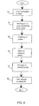
- the method of the invention for producing a prefabricated member bent to shape is carried out as illustrated schematically in figure 9.
- the mould base 23 is prepared for use, as shown schematically in figure 8. It is either built up especially for this purpose, or a previously made mould base is reused.
- the glue film is applied to the joint surfaces 14a, 15a of the surface plates 14, 15.
- the joint surfaces 13a, 13b on different sides of the core plate 13 are equipped with a seal 20, 21 in their border areas 18, 19 in step 93.
- the plates 13, 14, 15 are prefixed m step 94, in other words, they are placed on top of each other with the joint surfaces 13a, 13b, 14a, 15a facing each other.
- one plate i.e.
- the first surface plate 14 is disposed on the mould base 23, then the core plate 13 with the first joint surfaces 13a, 14a facing each other, and finally the third plate, i.e. the second surface plate 15 and the core plate 13 with the second joint surfaces 13b, 15a facing each other.
- suitable support means 24 are used for supporting plates 13, 14, 15 opposite one another and on the mould base 23.
- the seals 20, 21 seal the interstices between the plates 13, 14, 15 almost hermetically and the opening 22 can be connected to a suction pump or the like.
- a vacuum is conducted through the opening 22 via the grooves 16, 17 in the core plate 13 to the inner surface of the surface plates 14, 15 in step 95, the ambient atmospheric pressure pressing the surface plates 14, 15 into contact with the core plate 13.
- the pressing force required for the glueing is generated by the atmospheric pressure prevailing outside the plates.
- the glue is then allowed to dry in step 96.
- the bonding of the surface plates 14, 15 and the core plate 13 stiffens the prefabricated member to the desired shape, and any additional upper supports 24 which may have been used can now be removed.
- the vacuum is released through the opening 22 in step 97, and after this the prefabricated member is finished in principle.
- the prefabricated member is checked and trimmed by filling up the opening 22 among other things.
- a pretensioned prefabricated member is manufactured, which may be used for instance to carry a specific load while maintaining its predetermined shape which differs from the pretensioned shape.
- Moulded prefabricated members can also be manufactured by using a premoulded core plate.
- the glued surface plates are then placed on either side of the premoulded core plate equipped with seals.
- the core plate used may have deflections in many directions. After this, the steps 95-98 explained above are performed.
Landscapes
- Engineering & Computer Science (AREA)
- Architecture (AREA)
- Civil Engineering (AREA)
- Structural Engineering (AREA)
- Laminated Bodies (AREA)
Claims (10)
- Fertigteil, umfassend mindestens zwei Platten (1, 2; 6; 13, 14, 15), eine erste Platte, d.h. eine Kernplatte (1; 13), und eine zweite Platte, d.h. eine Oberflächenplatte (2; 6; 14, 15), wobei die erste und zweite Platte an deren gemeinsamen Oberflächen (1a, 2a; 1b, 6a; 13a, 14a; 13b, 15a), die mit einem Klebefilm (11, 12) versehen sind, miteinander verbunden sind, wobei die erste Platte (1; 13) auf ihrer gemeinsamen Oberfläche (1a; 1b; 13a, 13b) mindestens eine Gruppe miteinander verbundener Rillen (3, 3a, 3b; 7, 7a, 7b; 16, 17) aufweist, wodurch ein gerippter Bereich (4; 8) gebildet wird, wobei die erste Platte (1; 13) zumindest während der Herstellungsphase des Fertigteils eine Öffnung (5) zum Erzeugen eines Vakuums umfasst, die an der einen Seite mit den Rillen (3, 3a, 3b; 7, 7a, 7b; 16, 17) und an der anderen Seite mit der Außenseite der Platte (1; 13) verbunden ist, dadurch gekennzeichnet, dass eine Versiegelung (10; 10a, 10b; 20) mit Verbindungsoberflächen um den gerippten Bereich (4; 8) angeordnet ist, welcher durch die Rillen (3, 3a, 3b; 7, 7a, 7b; 16, 17) zwischen den gemeinsamen Oberflächen (1a, 2a; 1b, 6a; 13a, 14a; 13b, 15a) der Platten gebildet wird, wobei die Versiegelung zur Vorbefestigung der gemeinsamen Oberflächen der Platten aneinander dient, um in der Herstellungsphase des Fertigteils eine zumindest teilweise hermetische Begrenzung um den gerippten Bereich zu erhalten.
- Fertigteil nach Anspruch 1, dadurch gekennzeichnet, dass die Versiegelung (10; 10a, 10b; 20) im Randbereich (9; 9a, 9b; 18, 19) der gemeinsamen Oberflächen (1a, 2a; 1b, 6a; 13a, 14a; 13b, 15a) der Platten (1, 2; 6; 13, 14, 15) angeordnet wurde.
- Fertigteil nach Anspruch 1 oder 2, dadurch gekennzeichnet, dass die Versiegelung (1; 10a, 10b; 20) ein Siegelband oder Klebefilm ist.
- Fertigteil nach Anspruch 1, 2 oder 3, dadurch gekennzeichnet, dass die Versiegelung (10; 10a, 10b; 20) mindestens 10 bis 30 mm breit ist.
- Fertigteil nach einem der vorangehenden Ansprüche 1 bis 4, dadurch gekennzeichnet, dass die erste Platte, d.h. die Kernplatte (1), eine dicke Kunststoffschaumplatte ist und die zweite Platte, d.h. die Oberflächenplatte (2; 6; 14, 15), eins der folgenden ist: eine Furnierplatte, eine dicke Holzplatte oder eine dünne Metallplatte.
- Verfahren zur Herstellung von Fertigteilen, die mindestens zwei Platten (1, 2; 6; 13, 14, 15), eine erste Platte, d.h. eine Kernplatte (1; 13) und eine zweite Platte, d.h. eine Oberflächenplatte (2; 6; 14, 15), umfassen, wobei die erste und zweite Platte an deren gemeinsamen Oberflächen (1a, 2a; 1b, 6a; 13a, 14a; 13b, 15a) miteinander verbunden sind, wobei die erste Platte (1; 13) auf ihrer gemeinsamen Oberfläche (1a; 1b; 13a, 13b) mindestens eine Gruppe miteinander verbundener Rillen (3, 3a, 3b; 7, 7a, 7b; 16, 17) aufweist, wodurch ein gerippter Bereich (4;8) entsteht, wobei die erste Platte (1; 13) zumindest in der Herstellungsphase des Fertigteils eine Öffnung (5) umfasst, die an der einen Seite mit den Rillen (3, 3a, 3b; 7, 7a, 7b; 16, 17) und an der anderen Seite mit der Außenseite der Platte (1; 13) verbunden ist; wobeiein Klebefilm (11, 12) auf mindestens eine der gemeinsamen Oberflächen (1a, 2a; 1b, 6a; 13a, 14a; 13b, 15a) der Platten aufgebracht ist;die Platten (1, 2; 6; 13, 14, 15) so plaziert werden, dass sich deren gemeinsame Oberflächen (1a, 2a; 1b, 6a; 13a, 14a; 13b, 15a) gegenüberliegen, wobei anschließenddurch die Öffnung (5) ein Vakuum in den Rillen (3, 3a, 3b; 7, 7a, 7b; 16, 17) und zwischen den Platten (1, 2; 6; 13, 14, 15) erzeugt wird, wobei der umgebende atmosphärische Druck die gemeinsamen Oberflächen (1a, 2a; 1b, 6a; 13a, 14a; 13b, 15a) gegeneinander drückt, so dass die Platten aufgrund des Klebefilms (11, 12) miteinander verbunden werden, wobei anschließenddas Vakuum beendet und das Fertigteil fertiggestellt wird, dadurch gekennzeichnet, dasseine mit Verbindungsoberflächen versehene Versiegelung (10; 10a, 10b; 20) um den gerippten Bereich (4; 8), der durch die Rillen (3, 3a, 3b; 7, 7a, 7b; 16, 17) zwischen den gemeinsamen Oberflächen (1a, 2a; 1b, 6a; 13a, 14a; 13b, 15a) der Platten gebildet wird, angeordnet wird, wobei die Versiegelung zur Vorbefestigung der gemeinsamen Oberflächen der Platten (1, 2; 6; 13, 14, 15) aneinander dient, um zum Zeitpunkt der Erzeugung und der Verwendung des Vakuums eine zumindest teilweise hermetische Begrenzung der gemeinsamen Oberflächen (1a, 2a; 1b, 6a; 13a, 14a; 13b, 15a) um den gerippten Bericht zu erhalten.
- Verfahren nach Anspruch 6 zur Herstellung eines Fertigteils, dadurch gekennzeichnet, dass die versiegelung (10; 10a, 10b; 20) sich auf mindestens einer der gemeinsamen Oberflächen (1a, 2a; 1b, 6a; 13a, 14a; 13b, 15a) der Platten befindet.
- Verfahren nach einem der Ansprüche 6 oder 7 zur Herstellung eines Fertigteils, dadurch gekennzeichnet, dass die Versiegelung (10; 10a, 10b; 20) im Randbereich (9; 9a, 9b; 18, 19) der gemeinsamen Oberflächen (1a, 2a; 1b, 6a; 13a, 14a; 13b, 15a) der Platten (1, 2; 6; 13, 14, 15) angeordnet ist.
- Verfahren nach einem der Ansprüche 6, 7 oder 8 zur Herstellung eines Fertigteils, dadurch gekennzeichnet, dass die Versiegelung (10; 10a, 10b; 20) mindestens über eine Breite von 10 bis 30 mm angeordnet ist.
- Verfahren zur Herstellung eines Fertigteils nach einem der vorangehenden Ansprüche 6 bis 9, dadurch gekennzeichnet, dass die Platten (13, 14, 15) im Verhältnis zueinander und in der gewünschten Form angeordnet werden, bevor die tatsächliche Verklebung durchgeführt wird.
Priority Applications (1)
| Application Number | Priority Date | Filing Date | Title |
|---|---|---|---|
| DK98955629T DK1038074T3 (da) | 1998-11-25 | 1998-11-25 | Fremgangsmåde til fremstilling af et præfabrikeret element og et præfabrikeret element |
Applications Claiming Priority (3)
| Application Number | Priority Date | Filing Date | Title |
|---|---|---|---|
| FI974332A FI105845B (fi) | 1997-11-26 | 1997-11-26 | Menetelmä kerroselementin valmistamiseksi ja kerroselementti |
| FI974332 | 1997-11-26 | ||
| PCT/FI1998/000923 WO1999027209A1 (en) | 1997-11-26 | 1998-11-25 | Method for producing a prefabricated member and a prefabricated member |
Publications (2)
| Publication Number | Publication Date |
|---|---|
| EP1038074A1 EP1038074A1 (de) | 2000-09-27 |
| EP1038074B1 true EP1038074B1 (de) | 2004-07-14 |
Family
ID=8550013
Family Applications (1)
| Application Number | Title | Priority Date | Filing Date |
|---|---|---|---|
| EP98955629A Expired - Lifetime EP1038074B1 (de) | 1997-11-26 | 1998-11-25 | Verfahren zur herstellung eines fertigteils und fertigteil |
Country Status (5)
| Country | Link |
|---|---|
| EP (1) | EP1038074B1 (de) |
| AU (1) | AU1239999A (de) |
| DE (1) | DE69825076T2 (de) |
| FI (1) | FI105845B (de) |
| WO (1) | WO1999027209A1 (de) |
Families Citing this family (4)
| Publication number | Priority date | Publication date | Assignee | Title |
|---|---|---|---|---|
| DE19946745C1 (de) * | 1999-09-29 | 2001-04-05 | Siemens Ag | Klebeverfahren |
| EP1771709A4 (de) * | 2004-07-26 | 2009-10-28 | Sikongsa Co Ltd | Gekrümmtes paneel für schalldämmungsverkleidung, verfahren zu seiner herstellung und schalldämmungsverkleidung damit |
| WO2015071544A1 (en) * | 2013-11-15 | 2015-05-21 | Wimacor Oy | Method for manufacturing cargo container, and panel element for a cargo container |
| FI127480B (fi) * | 2016-07-13 | 2018-06-29 | Hannu Vilen | Menetelmä elementin valmistamiseksi ja vastaava elementti |
Family Cites Families (4)
| Publication number | Priority date | Publication date | Assignee | Title |
|---|---|---|---|---|
| US2700632A (en) * | 1949-09-09 | 1955-01-25 | Northrop Aircraft Inc | Method of making a honeycomb sandwich |
| FR1301300A (fr) * | 1961-06-22 | 1962-08-17 | Hamburger Flugzeugbau Gmbh | Procédé de fabrication d'éléments cellulaires en forme de plaques et éléments conformes à ceux obtenus |
| DK144429C (da) * | 1979-12-12 | 1982-08-23 | Superfos Glasuld As | Fremgangsmaade ved fremstilling af et byggeelement |
| FI94277C (fi) * | 1993-12-31 | 1995-08-10 | Hannu Wilen | Menetelmä kerroselementtien valmistamiseksi |
-
1997
- 1997-11-26 FI FI974332A patent/FI105845B/fi not_active IP Right Cessation
-
1998
- 1998-11-25 EP EP98955629A patent/EP1038074B1/de not_active Expired - Lifetime
- 1998-11-25 DE DE69825076T patent/DE69825076T2/de not_active Expired - Lifetime
- 1998-11-25 AU AU12399/99A patent/AU1239999A/en not_active Abandoned
- 1998-11-25 WO PCT/FI1998/000923 patent/WO1999027209A1/en not_active Ceased
Also Published As
| Publication number | Publication date |
|---|---|
| FI105845B (fi) | 2000-10-13 |
| WO1999027209A1 (en) | 1999-06-03 |
| FI974332A0 (fi) | 1997-11-26 |
| DE69825076D1 (de) | 2004-08-19 |
| EP1038074A1 (de) | 2000-09-27 |
| DE69825076T2 (de) | 2005-07-21 |
| FI974332A7 (fi) | 1999-05-27 |
| AU1239999A (en) | 1999-06-15 |
Similar Documents
| Publication | Publication Date | Title |
|---|---|---|
| EP1774128B1 (de) | Hoch wärme- und schalldämpfendes vakuum-isolationspaneel | |
| US6279284B1 (en) | Composite vapor barrier panel | |
| KR100837135B1 (ko) | 밀봉재 지지 부재를 가진 연속적인 가요성 스페이서 조립체 | |
| US10647021B2 (en) | Fibreboard | |
| JP4361863B2 (ja) | マット状無機繊維製断熱材およびその梱包体 | |
| MXPA02002552A (es) | Metodo para producir un panel emparedado y un componente de carroceria. | |
| EP1038074B1 (de) | Verfahren zur herstellung eines fertigteils und fertigteil | |
| FI66963B (fi) | Foerfarande foer framstaellning av ett byggelement | |
| US4539241A (en) | Procedure for manufacturing a building element, and the building element | |
| CN210369677U (zh) | 一种具有隔热功能的节能型墙板 | |
| JP5130108B2 (ja) | 建築用パネル材の製造方法 | |
| JPH01257398A (ja) | 電波吸収パネルの製造方法 | |
| FI94277B (fi) | Menetelmä kerroselementtien valmistamiseksi | |
| RU237479U1 (ru) | Мебельная панель | |
| JPS6118118Y2 (de) | ||
| CN215291082U (zh) | 一种建筑装饰用铝蜂窝板 | |
| JP4943877B2 (ja) | 圧縮繊維パネルおよび圧縮繊維パネルの製造方法 | |
| WO2020023983A4 (en) | Core and method for automated hollow door and panel assembly | |
| JP3398836B2 (ja) | パネル製造装置 | |
| FI62699B (fi) | Laodbalk av sandwichkonstruktion och foerfarande foer dess framstaellning | |
| JP3255019B2 (ja) | ド ア | |
| JPH01263041A (ja) | 断熱構造体およびその製造方法 | |
| JP3272590B2 (ja) | 断熱パネル | |
| JPS6339420B2 (de) | ||
| JPS6220250Y2 (de) |
Legal Events
| Date | Code | Title | Description |
|---|---|---|---|
| PUAI | Public reference made under article 153(3) epc to a published international application that has entered the european phase |
Free format text: ORIGINAL CODE: 0009012 |
|
| 17P | Request for examination filed |
Effective date: 20000619 |
|
| AK | Designated contracting states |
Kind code of ref document: A1 Designated state(s): DE DK FR GB SE |
|
| 17Q | First examination report despatched |
Effective date: 20030321 |
|
| GRAP | Despatch of communication of intention to grant a patent |
Free format text: ORIGINAL CODE: EPIDOSNIGR1 |
|
| GRAS | Grant fee paid |
Free format text: ORIGINAL CODE: EPIDOSNIGR3 |
|
| GRAA | (expected) grant |
Free format text: ORIGINAL CODE: 0009210 |
|
| AK | Designated contracting states |
Kind code of ref document: B1 Designated state(s): DE DK FR GB SE |
|
| REG | Reference to a national code |
Ref country code: GB Ref legal event code: FG4D |
|
| REF | Corresponds to: |
Ref document number: 69825076 Country of ref document: DE Date of ref document: 20040819 Kind code of ref document: P |
|
| REG | Reference to a national code |
Ref country code: SE Ref legal event code: TRGR |
|
| REG | Reference to a national code |
Ref country code: DK Ref legal event code: T3 |
|
| ET | Fr: translation filed | ||
| PLBE | No opposition filed within time limit |
Free format text: ORIGINAL CODE: 0009261 |
|
| STAA | Information on the status of an ep patent application or granted ep patent |
Free format text: STATUS: NO OPPOSITION FILED WITHIN TIME LIMIT |
|
| 26N | No opposition filed |
Effective date: 20050415 |
|
| PGFP | Annual fee paid to national office [announced via postgrant information from national office to epo] |
Ref country code: DK Payment date: 20141128 Year of fee payment: 17 |
|
| PGFP | Annual fee paid to national office [announced via postgrant information from national office to epo] |
Ref country code: GB Payment date: 20141128 Year of fee payment: 17 Ref country code: DE Payment date: 20141201 Year of fee payment: 17 Ref country code: SE Payment date: 20141128 Year of fee payment: 17 |
|
| PGFP | Annual fee paid to national office [announced via postgrant information from national office to epo] |
Ref country code: FR Payment date: 20141201 Year of fee payment: 17 |
|
| REG | Reference to a national code |
Ref country code: DE Ref legal event code: R119 Ref document number: 69825076 Country of ref document: DE |
|
| REG | Reference to a national code |
Ref country code: DK Ref legal event code: EBP Effective date: 20151130 |
|
| GBPC | Gb: european patent ceased through non-payment of renewal fee |
Effective date: 20151125 |
|
| REG | Reference to a national code |
Ref country code: FR Ref legal event code: ST Effective date: 20160729 |
|
| PG25 | Lapsed in a contracting state [announced via postgrant information from national office to epo] |
Ref country code: SE Free format text: LAPSE BECAUSE OF NON-PAYMENT OF DUE FEES Effective date: 20151126 |
|
| PG25 | Lapsed in a contracting state [announced via postgrant information from national office to epo] |
Ref country code: DE Free format text: LAPSE BECAUSE OF NON-PAYMENT OF DUE FEES Effective date: 20160601 Ref country code: GB Free format text: LAPSE BECAUSE OF NON-PAYMENT OF DUE FEES Effective date: 20151125 Ref country code: DK Free format text: LAPSE BECAUSE OF NON-PAYMENT OF DUE FEES Effective date: 20151130 |
|
| PG25 | Lapsed in a contracting state [announced via postgrant information from national office to epo] |
Ref country code: FR Free format text: LAPSE BECAUSE OF NON-PAYMENT OF DUE FEES Effective date: 20151130 |