EP1038052B1 - Remote cathodic protection monitoring system - Google Patents
Remote cathodic protection monitoring system Download PDFInfo
- Publication number
- EP1038052B1 EP1038052B1 EP98912133A EP98912133A EP1038052B1 EP 1038052 B1 EP1038052 B1 EP 1038052B1 EP 98912133 A EP98912133 A EP 98912133A EP 98912133 A EP98912133 A EP 98912133A EP 1038052 B1 EP1038052 B1 EP 1038052B1
- Authority
- EP
- European Patent Office
- Prior art keywords
- cathodic protection
- transponder
- monitoring system
- accordance
- reference electrode
- Prior art date
- Legal status (The legal status is an assumption and is not a legal conclusion. Google has not performed a legal analysis and makes no representation as to the accuracy of the status listed.)
- Expired - Lifetime
Links
- 238000004210 cathodic protection Methods 0.000 title claims abstract description 71
- 238000012544 monitoring process Methods 0.000 title claims abstract description 32
- 229910052751 metal Inorganic materials 0.000 claims abstract description 38
- 239000002184 metal Substances 0.000 claims abstract description 38
- 238000000034 method Methods 0.000 claims description 6
- 239000003990 capacitor Substances 0.000 claims description 5
- 239000000872 buffer Substances 0.000 claims description 4
- RYGMFSIKBFXOCR-UHFFFAOYSA-N Copper Chemical compound [Cu] RYGMFSIKBFXOCR-UHFFFAOYSA-N 0.000 claims description 3
- 229910052802 copper Inorganic materials 0.000 claims description 3
- 239000010949 copper Substances 0.000 claims description 3
- 229910000365 copper sulfate Inorganic materials 0.000 claims description 3
- ARUVKPQLZAKDPS-UHFFFAOYSA-L copper(II) sulfate Chemical compound [Cu+2].[O-][S+2]([O-])([O-])[O-] ARUVKPQLZAKDPS-UHFFFAOYSA-L 0.000 claims description 3
- FYYHWMGAXLPEAU-UHFFFAOYSA-N Magnesium Chemical compound [Mg] FYYHWMGAXLPEAU-UHFFFAOYSA-N 0.000 claims description 2
- HCHKCACWOHOZIP-UHFFFAOYSA-N Zinc Chemical compound [Zn] HCHKCACWOHOZIP-UHFFFAOYSA-N 0.000 claims description 2
- 230000015556 catabolic process Effects 0.000 claims description 2
- 229910052749 magnesium Inorganic materials 0.000 claims description 2
- 239000011777 magnesium Substances 0.000 claims description 2
- 229910052725 zinc Inorganic materials 0.000 claims description 2
- 239000011701 zinc Substances 0.000 claims description 2
- 239000002689 soil Substances 0.000 description 15
- 238000005259 measurement Methods 0.000 description 10
- 238000010586 diagram Methods 0.000 description 5
- 238000012360 testing method Methods 0.000 description 5
- 230000005540 biological transmission Effects 0.000 description 3
- 230000007797 corrosion Effects 0.000 description 3
- 238000005260 corrosion Methods 0.000 description 3
- 230000010287 polarization Effects 0.000 description 3
- 229960000355 copper sulfate Drugs 0.000 description 2
- 230000000694 effects Effects 0.000 description 2
- VNWKTOKETHGBQD-UHFFFAOYSA-N methane Chemical compound C VNWKTOKETHGBQD-UHFFFAOYSA-N 0.000 description 2
- 238000012806 monitoring device Methods 0.000 description 2
- 238000005056 compaction Methods 0.000 description 1
- 239000004020 conductor Substances 0.000 description 1
- 238000002592 echocardiography Methods 0.000 description 1
- 239000008151 electrolyte solution Substances 0.000 description 1
- 239000007789 gas Substances 0.000 description 1
- 238000009434 installation Methods 0.000 description 1
- WABPQHHGFIMREM-UHFFFAOYSA-N lead(0) Chemical compound [Pb] WABPQHHGFIMREM-UHFFFAOYSA-N 0.000 description 1
- 238000012423 maintenance Methods 0.000 description 1
- 239000002923 metal particle Substances 0.000 description 1
- 239000000203 mixture Substances 0.000 description 1
- 239000003345 natural gas Substances 0.000 description 1
- 238000007747 plating Methods 0.000 description 1
- 239000000523 sample Substances 0.000 description 1
- 230000008054 signal transmission Effects 0.000 description 1
- 239000007787 solid Substances 0.000 description 1
- 238000009987 spinning Methods 0.000 description 1
- 239000000126 substance Substances 0.000 description 1
- 230000000007 visual effect Effects 0.000 description 1
- XLYOFNOQVPJJNP-UHFFFAOYSA-N water Substances O XLYOFNOQVPJJNP-UHFFFAOYSA-N 0.000 description 1
Images


Classifications
-
- C—CHEMISTRY; METALLURGY
- C23—COATING METALLIC MATERIAL; COATING MATERIAL WITH METALLIC MATERIAL; CHEMICAL SURFACE TREATMENT; DIFFUSION TREATMENT OF METALLIC MATERIAL; COATING BY VACUUM EVAPORATION, BY SPUTTERING, BY ION IMPLANTATION OR BY CHEMICAL VAPOUR DEPOSITION, IN GENERAL; INHIBITING CORROSION OF METALLIC MATERIAL OR INCRUSTATION IN GENERAL
- C23F—NON-MECHANICAL REMOVAL OF METALLIC MATERIAL FROM SURFACE; INHIBITING CORROSION OF METALLIC MATERIAL OR INCRUSTATION IN GENERAL; MULTI-STEP PROCESSES FOR SURFACE TREATMENT OF METALLIC MATERIAL INVOLVING AT LEAST ONE PROCESS PROVIDED FOR IN CLASS C23 AND AT LEAST ONE PROCESS COVERED BY SUBCLASS C21D OR C22F OR CLASS C25
- C23F13/00—Inhibiting corrosion of metals by anodic or cathodic protection
- C23F13/02—Inhibiting corrosion of metals by anodic or cathodic protection cathodic; Selection of conditions, parameters or procedures for cathodic protection, e.g. of electrical conditions
- C23F13/06—Constructional parts, or assemblies of cathodic-protection apparatus
- C23F13/08—Electrodes specially adapted for inhibiting corrosion by cathodic protection; Manufacture thereof; Conducting electric current thereto
- C23F13/22—Monitoring arrangements therefor
Definitions
- This invention relates to a transponder/cathodic protection system that generates surface detectable signals that can be used to monitor and measure the effectiveness of a buried cathodic protection circuit for buried metal objects, in particular, buried metal pipes.
- the transponder which is buried, converts the voltage and amperage generated by a typical cathodic protection circuit into radio frequency waves that can be detected remotely above ground by any suitable transmitter-receiver tuned to the transponder frequency.
- Underground metal objects such as natural gas distribution and transmission pipelines, tend to build up electrical charges caused by the earth's magnetic field.
- the metal object also serves as a conductor between soils of differing chemical composition and conductivity, in effect, forming a battery and setting up circulating currents in the pipe-soil system. After a length of time, depending upon soil conductivity and conditions, the metal object will become sufficiently charged such that an electrical discharge will occur from the metal object to the ground, causing corrosion of the metal object.
- the electrical discharge causes metal particles to be carried away from the pipe, thereby pitting the pipe which, in turn, can cause a hole to develop at the point of discharge.
- U.S. Patent 5,216,370 teaches a cathodic protection monitoring system which provides IR drop free cathodic protection potential measurements which are indicative of the effectiveness of the cathodic protection system.
- the system measures the polarized potential between a reference electrode and a coupon subsequent to decoupling the coupon from the protected structure.
- the system controls the time or times at which the potential is measured in order to ensure that the potential is measured only after the polarized potential has achieved a relatively steady state value.
- the system includes an above ground test module including a timing circuit and voltmeter, the test module being removably electrically attached to a switch network by way of terminals.
- the reference electrode is electrically coupled to the test module by way of an electrical cable; similarly, the coupon and metal structure are electrically coupled to the switch network using electrical cables.
- a cathodic protection measurement system including a coupon buried near and electrically connected to a pipeline so as to receive the same level of cathodic protection current as the pipeline is taught by U.S. Patent 5,469,048.
- a test wire is connected to the pipeline and routed to a normally closed contact switch located at an access point of an above ground test station. The switch is also connected to a coupon wire, which is routed and connected to the coupon to complete the electrical connection.
- a reference electrode having a measuring surface contacting the soil close to the buried coupon includes an electrode wire provided to the access point, the access point comprising a tubular access tube which penetrates the soil and extends to the pipeline being protected.
- U.S. Patent 5,144,247 teaches an apparatus for measuring cathodic protection voltage levels on a concealed conductive structure which includes a probe having a standard half cell reference electrode, a working electrode, and an auxiliary electrode mounted in a fixed spacial relationship to each other. wherein the reference electrode, working electrode and auxiliary electrode are each in contact with an electrolytic solution.
- a voltage measuring device is provided for receiving the voltage from the reference electrode.
- a switch is included for connecting and disconnecting the working electrode to the common reference point. See also U.S. Patent 5,446,369 which also teaches a corrosion monitoring system.
- the urban environment offers particular challenges to carrying out the operation of cathodic protection monitoring.
- a portable reference electrode can not be used when there is no unpaved soil nearby in which to insert the electrode. Measurements can be taken using a permanently buried electrode if lead wires are brought to the surface from the pipe and the electrode.
- One practice is to bring both of these lead wires to the surface in a common valve box that can be opened when a cathodic protection survey is being performed.
- These valve boxes can be buried, paved over, or otherwise "lost" in the shifting urban landscape.
- Patent 3,860,912 teaches a power supply monitoring device for monitoring remote power line connected cathodic protection rectifier operation along a pipeline from pipeline patrol vehicles.
- the device comprises transmitter means disposed adjacent to each power supply rectifier and operably connected to the power line for transmitting a signal, monitoring means operably connected to the output of the cathodic protection rectifier for sensing the output current thereof, signal modulating means operably connected between the monitor means and the transmitter means for modulating the transmitter signal in accordance with the rectifier current level, receiver means disposed within the patrol vehicle for receiving the output of the transmitter means when the patrol vehicle is in the near proximity of the rectifier, and audio output means operably connected to the receiver means for indicating the cathodic protection rectifier current level.
- a significant portion of the monitoring device is disposed above ground and is physically connected to the below ground components.
- a cathodic protection monitoring system for buried metal objects such as buried metal pipes, in accordance with one embodiment of this invention, comprises a transponder, a sacrificial anode, and a reference electrode, each of which is buried underground in close proximity to the buried metal object to be protected.
- the sacrificial anode is hard-wire connected to the transponder as is the reference electrode.
- a first principal circuit is formed between the sacrificial anode and the buried metal object and a second principal circuit is formed between the reference electrode and the buried metal object.
- a portable transceiver tuned to a frequency of the transponder is disposed above ground.
- the transponder converts voltage and amperage generated by the principal circuits into radio frequency (RF) waves detectable by the transceiver.
- RF radio frequency
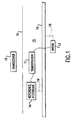
- a cathodic protection monitoring system for buried metal objects in accordance with one embodiment of this invention is schematically shown in Fig. 1.
- the cathodic protection monitoring system comprises transponder 11 hard-wire connected to sacrificial anode 13 and reference electrode 14.
- Each of transponder 11, sacrificial anode 13, and reference electrode 14 is buried below ground 16 in close proximity to a buried metal object to be protected, in the instant case metal pipe 10.
- a first principal circuit 18 is. thus, formed between sacrificial anode 13 and metal pipe 10 and a second principal circuit 19 is formed between reference electrode 14 and pipe 10.
- Portable transceiver 12 is disposed above ground and is tuned to a frequency of transponder 11.
- the cathodic protection system of this invention generates, preferably upon demand, signals which are detectable above ground by transceiver 12.
- signals are preferably radio frequency (RF) waves that can be used to monitor and measure the effectiveness of the cathodic protection circuit.
- RF waves radio frequency
- transponder 11 being RF responsive, converts the voltage and amperage generated by a typical cathodic protection circuit into RF waves that can be detected remotely above ground by transceiver 12 tuned to the transponder frequency.
- Transponder 11 comprises analog-to-digital converter (ADC) 17, DC/DC converter 23, controller 24, antenna 28, high impedance buffers 22, switches 20, 21, 27, scaling resistor 26 and capacitor 25.
- ADC analog-to-digital converter
- Transponder 11 forms two principal circuits, first principal circuit between pipe 10 and sacrificial anode 13 and second principal circuit between pipe 10 and reference electrode 14.
- Sacrificial anode 13 and reference electrode 14 are hard wired to transponder 10, leaving soil 15 to complete each of first principal circuit 18 and second principal circuit 19.
- a hard-wire portion of each circuit contains a switch, 20 and 21 so that either principal circuit can be made or broken as desired using controller 24 to operate the appropriate switch 20, 21.
- transceiver 12 disposed above ground and controller 24 of transponder 11 communicate through encoded RF waves such that the desired switches 20, 21 can be opened or closed and the desired voltages and amperages measured upon demand.
- the circuit comprising pipe 10 and sacrificial anode 13 comprises resistor 26 which is sized to produce a small voltage, preferably less than about 0.2 volts, between resistor 26 and buried metal pipe 10. Voltages above about 0.2 volts jeopardize the cathodic protection afforded by the cathodic protection circuit and, thus, are not deemed to be suitable.
- DC/DC converter 23 and capacitor 25 are used to maintain a steady voltage for analog-to-digital converter 17 and antenna system 28. Said voltage is preferably less than about 5.5 volts and is preferably about 3.3 volts.
- switch 21 is closed completing the circuit between sacrificial anode 13 and pipe 10, thereby providing continuous, steady state, cathodic protection to pipe 10.
- Switch 20, preferably a double pole/double throw switch, connects reference electrode 14 and pipe 10 to analog-to-digital converter 17 through high impedance buffers 22, thereby measuring the steady state pipe to soil voltage. This voltage is converted from analog to digital values in analog-to-digital converter 17 and routed to antenna 28 by controller 24.
- RF waves generated by antenna 28, being indicative of the steady state pipe to soil voltage generated by the cathodic protection circuit, are intercepted at the surface by transceiver 12 tuned to the frequency of antenna 28.
- Instant-off voltages of the cathodic protection circuit indicates the level of polarization at the surface of pipe 10. Its decay rate indicates corrosion activity.
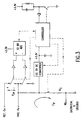
- the circuit for measuring this decay rate is shown in Fig. 5.
- Switch 21 is momentarily opened causing an immediate decay in the voltage of the circuit and a corresponding decay in the voltage input to analog-to-digital converter 17 and, thus, in the RF waves emitted by antenna 28 and detected by surface transceiver 12.
- capacitor 25 maintains the supply voltage at about 3.3 volts.
- switch 21 is again closed, returning the cathodic protection circuit to its normal, steady state mode of operation. Because of possible failure, switch 21 is preferably designed to fail closed, thus assuring continuous operation of the cathodic protection circuit.
- the cathodic protection circuit set to measure the steady state amperage thereof comprises switch 20 positioned to open the connection between reference electrode 14 and analog-to-digital converter/ground 17 through buffer 22b.
- the voltage difference at analog-to-digital converter 17, which is indicative of the amperage flow in the cathodic protection circuit, depending on the size of resistor 26, is converted to analog to digital values and routed to antenna 28 for transmission to surface transceiver 12.
- Signal transmission is effected by the intermittent operation of switch 27 which completes the antenna-to-ground circuit when closed, thereby energizing antenna 28.
- antenna 28 When energized, emits RF waves indicative of the appropriate measurement.
- the circuit for measurement of steady state pipe to soil voltage and amperage and the rate of voltage decay of the cathodic protection circuit is shown in Fig. 3 by which the effectiveness of the circuit, its continuity, polarization, protection level and remaining life of the sacrificial anode, can be determined.
- Power for transponder 11 is provided, in accordance with one embodiment, from the surface by an electromagnetic coupler or in accordance with another embodiment by power provided from a separate soil battery.
- a small amount of power is drawn from second principal circuit 19, or more preferably, from the cathodic protection circuit.
- the coupler is tuned to the same resonant frequency as antenna 28 which then acts as a resonator. In operation, an energy pulse is emitted from surface transceiver 12 and, when received by antenna 28, continues as stored energy which echoes back to surface transceiver 12.
- the cathodic protection and/or reference electrode voltage is then used to modify the duration of frequency, preferably the frequency of this echo pulse, thereby indicating the value of the modifying voltage.
- the stored energy is also used to operate other components, such as switches, of transponder 11.
- a separate buried antenna can be used for this purpose, or preferably, the antenna 28 of transponder 11 can be used.
- transponder 11 is programed to emit intermittent encoded signals which can be intercepted by surface transceiver 12 and used to locate the buried transponder/cathodic protection system, even if over-paved.
- switches can be used in transponder 11 although solid state switches are preferred because of their lack of moving parts and contact points, thereby eliminating the occurrence of contact point polarization and providing higher reliability.
- the sacrificial anode 13 is preferably made of zinc or magnesium.
- the reference electrode is preferably a standard half cell, in particular a copper/copper-sulfate half cell.
- a method for monitoring a cathodic protection system in accordance with one embodiment of this invention comprises converting a voltage generated by a cathodic protection circuit comprising a transponder, a sacrificial anode, and a reference electrode, all of which are buried underground in close proximity to a metal object being protected, from a analog value to a digital value, and routing the digital value to an antenna of said transponder which generates radio frequency waves.
- the radio frequency waves are then intercepted above ground by a transceiver tuned to a frequency of the antenna. An absence of the radio frequency waves is indicative of a breakdown in the cathodic protection circuit.
- transponder 11 can be easily modified and used to perform many other functions, such as detecting and/or measuring the water flow in underground pipes, sewers, tunnels and the like, the electrical flow in underground power lines, and the compaction of back fill or road base.
Landscapes
- Chemical & Material Sciences (AREA)
- Engineering & Computer Science (AREA)
- Materials Engineering (AREA)
- Mechanical Engineering (AREA)
- Metallurgy (AREA)
- Organic Chemistry (AREA)
- Prevention Of Electric Corrosion (AREA)
- Measurement Of Radiation (AREA)
- Investigating Or Analyzing Materials By The Use Of Electric Means (AREA)
- Two-Way Televisions, Distribution Of Moving Picture Or The Like (AREA)
- Remote Monitoring And Control Of Power-Distribution Networks (AREA)
- Selective Calling Equipment (AREA)
- Testing Resistance To Weather, Investigating Materials By Mechanical Methods (AREA)
Abstract
Description
Claims (11)
- A cathodic protection monitoring system for buried metal objects comprising:a transponder;a sacrificial anode hard-wire connected to said transponder;a reference electrode hard-wire connected to said transponder;each of said transponder, said sacrificial anode and said reference electrode buried underground in close proximity to a buried metal object to be protected, forming a first principal circuit between said sacrificial anode and said buried metal object and forming a second principal circuit between said reference electrode and said buried metal object; andsaid transponder converting a voltage and amperage generated by said principal circuits into radio frequency waves detectable by a portable transceiver disposed above ground. said portable transceiver tuned to a frequency of said transponder.
- A cathodic protection monitoring system in accordance with Claim 1, wherein said hard-wire portion of each said principal circuit comprises a switch.
- A cathodic protection monitoring system in accordance with Claim 2, wherein said switch in said second principal circuit is a double pole/double throw switch.
- A cathodic protection monitoring system in accordance with Claim 1, wherein said first principal circuit comprises at least one resistor sized to produce a voltage less than about 0.2 volt between said resistor and said buried metal object.
- A cathodic protection monitoring system in accordance with Claim 1, wherein said transponder comprises an analog-to-digital converter, a DC/DC converter, a controller. an antenna, at least one high impedance buffer, at least one switch, at least one scaling resistor. and at least one capacitor.
- A cathodic protection monitoring system in accordance with Claim 5 , wherein said DC/DC converter and said at least one capacitor maintain a steady voltage for said analog-to-digital converter and said antenna.
- A cathodic protection monitoring system in accordance with Claim 6 , wherein said steady voltage is less than about 5.5 volts.
- A cathodic protection monitoring system in accordance with Claim 1, wherein said sacrificial anode is one of zinc and magnesium.
- A cathodic protection monitoring system in accordance with Claim 1, wherein said reference electrode is a standard half cell.
- A cathodic protection monitoring system in accordance with Claim 9 , wherein said standard half cell is a copper/copper sulfate half cell.
- A method for monitoring a cathodic protection system comprising:converting a voltage generated by a cathodic protection circuit comprising a transponder, a sacrificial anode and a reference electrode, all of which are buried underground in close proximity to a metal object being protected, from an analog value to a digital value and routing said digital value to an antenna which generates radio frequency waves; andintercepting said radio frequency waves above ground with a transceiver tuned to a frequency of said antenna, whereby an absence of said radio frequency waves is indicative of a breakdown in said cathodic protection circuit.
Applications Claiming Priority (3)
| Application Number | Priority Date | Filing Date | Title |
|---|---|---|---|
| US08/967,963 US5999107A (en) | 1997-11-12 | 1997-11-12 | Remote cathodic protection monitoring system |
| US967963 | 1997-11-12 | ||
| PCT/US1998/006320 WO1999024641A1 (en) | 1997-11-12 | 1998-03-31 | Remote cathodic protection monitoring system |
Publications (2)
| Publication Number | Publication Date |
|---|---|
| EP1038052A1 EP1038052A1 (en) | 2000-09-27 |
| EP1038052B1 true EP1038052B1 (en) | 2001-07-11 |
Family
ID=25513533
Family Applications (1)
| Application Number | Title | Priority Date | Filing Date |
|---|---|---|---|
| EP98912133A Expired - Lifetime EP1038052B1 (en) | 1997-11-12 | 1998-03-31 | Remote cathodic protection monitoring system |
Country Status (9)
| Country | Link |
|---|---|
| US (1) | US5999107A (en) |
| EP (1) | EP1038052B1 (en) |
| JP (1) | JP2002501120A (en) |
| AT (1) | ATE203066T1 (en) |
| AU (1) | AU6592298A (en) |
| CA (1) | CA2309693A1 (en) |
| DE (1) | DE69801117D1 (en) |
| WO (1) | WO1999024641A1 (en) |
| ZA (1) | ZA984586B (en) |
Cited By (1)
| Publication number | Priority date | Publication date | Assignee | Title |
|---|---|---|---|---|
| GB2464972A (en) * | 2008-11-03 | 2010-05-05 | Mark Wilson | Cathodic protection monitoring system |
Families Citing this family (36)
| Publication number | Priority date | Publication date | Assignee | Title |
|---|---|---|---|---|
| US6788075B2 (en) * | 1999-07-13 | 2004-09-07 | Flight Refuelling Limited | Anode monitoring |
| US6388575B1 (en) | 1999-11-05 | 2002-05-14 | Industrial Technology, Inc. | Addressable underground marker |
| DK173635B1 (en) * | 1999-12-14 | 2001-05-14 | Mogens Balslev Raadgivende Ing | Method and apparatus for detecting interruption of protective current on cathodically protected structures |
| US6690182B2 (en) * | 2000-07-19 | 2004-02-10 | Virginia Technologies, Inc | Embeddable corrosion monitoring-instrument for steel reinforced structures |
| US6992594B2 (en) * | 2001-05-18 | 2006-01-31 | Douglas Dudley | Pipeline monitoring system |
| US6940409B1 (en) * | 2001-08-13 | 2005-09-06 | Potter Electric Signal Company | Fluid flow detector |
| US7027957B2 (en) * | 2001-10-12 | 2006-04-11 | American Innovations, Ltd. | Current interrupter assembly |
| US6690278B2 (en) | 2001-12-28 | 2004-02-10 | Gas Technology Institute | Electronic marker for metallic valve box covers |
| US7470356B2 (en) * | 2004-03-17 | 2008-12-30 | Kennecott Utah Copper Corporation | Wireless monitoring of two or more electrolytic cells using one monitoring device |
| PL1733076T3 (en) * | 2004-03-17 | 2017-07-31 | Kennecott Utah Copper Llc | Wireless electrolytic cell monitoring powered by ultra low bus voltage |
| US7034704B2 (en) * | 2004-05-24 | 2006-04-25 | Mahowald Peter H | System powered via signal on gas pipe |
| GB2431058B (en) * | 2004-05-24 | 2007-06-13 | Avago Technologies General Ip | System powered via signal on gas pipe |
| US20060019149A1 (en) * | 2004-07-21 | 2006-01-26 | Mahowald Peter H | Soil battery |
| US7238263B2 (en) * | 2004-09-24 | 2007-07-03 | California Corrosion Concepts, Inc. | Corrosion tester |
| US7190154B2 (en) * | 2005-05-31 | 2007-03-13 | General Electric Company | Method and system for measuring a condition of a structure |
| US20070284262A1 (en) * | 2006-06-09 | 2007-12-13 | Eugene Yanjun You | Method of Detecting Shorts and Bad Contacts in an Electrolytic Cell |
| ITFI20070062A1 (en) * | 2007-03-15 | 2008-09-16 | Caen Rfid Srl | APPARATUS FOR MEASURING THE CONSUMPTION OF SACRIFIZIAL ANODES. |
| US7901546B2 (en) * | 2008-03-14 | 2011-03-08 | M.C. Miller Co. | Monitoring methods, systems and apparatus for validating the operation of a current interrupter used in cathodic protection |
| DE102008026901B4 (en) * | 2008-06-05 | 2010-06-02 | Cellpack Gmbh | Data transmission system with location, identification and measurement function and a method for this purpose |
| US8317996B2 (en) * | 2008-06-25 | 2012-11-27 | Ab Volvo Penta | Auxiliary device, a marine surface vessel and a method for a sacrificial anode in a marine construction |
| US20110238347A1 (en) * | 2010-03-24 | 2011-09-29 | Elecsys Corporation | Apparatus and system for automated pipeline testing |
| US8652312B2 (en) | 2011-02-14 | 2014-02-18 | Saudi Arabian Oil Company | Cathodic protection assessment probe |
| EP2906735B1 (en) * | 2012-10-11 | 2022-03-30 | Sembcorp Marine Repairs & Upgrades Pte. Ltd. | System and method for providing corrosion protection of metallic structure using time varying electromagnetic wave |
| ES2402836B1 (en) * | 2012-12-03 | 2014-03-11 | Diagnostiqa Consultoría Técnica, S.L. | Cathodic protection station and method to measure the potential of cathodic protection |
| CN103014720B (en) * | 2012-12-06 | 2014-11-05 | 青岛雅合科技发展有限公司 | Large range long distance cathodic protection system and working method thereof |
| CN103147082B (en) * | 2013-03-25 | 2014-11-05 | 青岛雅合阴保工程技术有限公司 | Cathode protection device for controlling multiplexed output by utilizing polarization potential and operating method thereof |
| US9550247B2 (en) | 2013-07-18 | 2017-01-24 | Aps Materials, Inc. | Double coupon reference cell and methods of making same |
| KR101497585B1 (en) * | 2013-11-12 | 2015-03-02 | 코렐테크놀로지(주) | Rectifier module control device of cathodic protection system for condenser |
| US9856566B1 (en) | 2015-04-06 | 2018-01-02 | The United States Of America As Represented By The Secretary Of The Air Force | Methods and apparatus for monitoring a sacrificial anode |
| KR102450908B1 (en) * | 2020-11-13 | 2022-10-05 | 모루시스템 주식회사 | Footing diagnosis device |
| CN113007611B (en) * | 2021-02-18 | 2022-12-02 | 呼和浩特中燃城市燃气发展有限公司 | Monitoring system for gas pipeline crossing river bottom |
| US12105011B2 (en) * | 2021-07-12 | 2024-10-01 | Titan Hre Llc | Apparatus and system for automated assessment of cathodic protection system for pipelines |
| US12173414B2 (en) * | 2021-12-16 | 2024-12-24 | Xerox Corporation | Cathodic protection system and method |
| US20240151671A1 (en) * | 2022-11-05 | 2024-05-09 | Devon Mark Cioffi | Soil-powered LED Plant Moisture Meter |
| CN115950929B (en) * | 2022-12-29 | 2025-11-18 | 国家石油天然气管网集团有限公司 | A smart probe for DCVG and CIPS detection |
| CN119780199B (en) * | 2025-01-23 | 2025-08-08 | 北京安科管道工程科技有限公司 | Data recorder |
Family Cites Families (12)
| Publication number | Priority date | Publication date | Assignee | Title |
|---|---|---|---|---|
| US3860912A (en) * | 1973-08-08 | 1975-01-14 | Aviat Inc | Power supply monitoring device |
| NL181283C (en) * | 1975-12-17 | 1987-07-16 | Shell Int Research | SYSTEM FOR EXAMINING THE OPERATION OF A CATHODIC PROTECTIVE UNIT. |
| GB1557153A (en) * | 1977-08-04 | 1979-12-05 | Wilson Walton Int Ltd | Monitor for monitoring the potential of underwater metal-work |
| NL8103088A (en) * | 1981-06-26 | 1983-01-17 | Nederlandse Gasunie Nv | DEVICE FOR MEASURING THE POTENTIAL WITH REGARD TO THE BOTTOM OF A CATHODICALLY PROTECTED METAL CONSTRUCTION. |
| US4592818A (en) * | 1983-09-12 | 1986-06-03 | Outboard Marine Corporation | Cathodic protection system |
| US4573115A (en) * | 1983-10-28 | 1986-02-25 | Standard Oil Company (Indiana) | Supervisory control system for remotely monitoring and controlling at least one operational device |
| US4644285A (en) * | 1984-10-09 | 1987-02-17 | Wayne Graham & Associates International, Inc. | Method and apparatus for direct measurement of current density |
| US5144247A (en) * | 1991-02-14 | 1992-09-01 | Westinghouse Electric Corp. | Method and apparatus for reducing IR error in cathodic protection measurements |
| US5216370A (en) * | 1991-10-24 | 1993-06-01 | Corrpro Companies, Inc. | Method and system for measuring the polarized potential of a cathodically protected structures substantially IR drop free |
| AU5325094A (en) * | 1992-10-09 | 1994-05-09 | Battelle Memorial Institute | Corrosion monitor system |
| US5469048A (en) * | 1994-06-13 | 1995-11-21 | Meridian Oil Inc. | Cathodic protection measurement apparatus |
| US5785842A (en) * | 1995-04-17 | 1998-07-28 | Speck; Robert M. | Corrosion protection monitoring and adjustment system |
-
1997
- 1997-11-12 US US08/967,963 patent/US5999107A/en not_active Expired - Lifetime
-
1998
- 1998-03-31 AU AU65922/98A patent/AU6592298A/en not_active Abandoned
- 1998-03-31 AT AT98912133T patent/ATE203066T1/en not_active IP Right Cessation
- 1998-03-31 EP EP98912133A patent/EP1038052B1/en not_active Expired - Lifetime
- 1998-03-31 CA CA002309693A patent/CA2309693A1/en not_active Abandoned
- 1998-03-31 DE DE69801117T patent/DE69801117D1/en not_active Expired - Lifetime
- 1998-03-31 WO PCT/US1998/006320 patent/WO1999024641A1/en not_active Ceased
- 1998-03-31 JP JP2000519630A patent/JP2002501120A/en not_active Ceased
- 1998-05-28 ZA ZA984586A patent/ZA984586B/en unknown
Cited By (1)
| Publication number | Priority date | Publication date | Assignee | Title |
|---|---|---|---|---|
| GB2464972A (en) * | 2008-11-03 | 2010-05-05 | Mark Wilson | Cathodic protection monitoring system |
Also Published As
| Publication number | Publication date |
|---|---|
| DE69801117D1 (en) | 2001-08-16 |
| EP1038052A1 (en) | 2000-09-27 |
| JP2002501120A (en) | 2002-01-15 |
| US5999107A (en) | 1999-12-07 |
| ATE203066T1 (en) | 2001-07-15 |
| ZA984586B (en) | 1998-12-21 |
| AU6592298A (en) | 1999-05-31 |
| CA2309693A1 (en) | 1999-05-20 |
| WO1999024641A1 (en) | 1999-05-20 |
Similar Documents
| Publication | Publication Date | Title |
|---|---|---|
| EP1038052B1 (en) | Remote cathodic protection monitoring system | |
| US20110238347A1 (en) | Apparatus and system for automated pipeline testing | |
| KR100537899B1 (en) | Data logger apparatus for measurement stray current of subway and power line | |
| CN104254788B (en) | Buried facility detection | |
| US4061965A (en) | Method and apparatus for monitoring a cathodically protected corrodible hollow member | |
| US6835291B2 (en) | Anode monitoring and subsea pipeline power transmission | |
| EP0148267B1 (en) | Method and device for detecting damage to buried object | |
| JPS6312942B2 (en) | ||
| US7019531B2 (en) | Procedure and device for the evaluation of the quality of a cable | |
| KR20000024667A (en) | Detection techniques method for the survey of buried structures by used gpr system | |
| CN210127273U (en) | Sleeve insulation monitoring device | |
| KR200215750Y1 (en) | Wireless measuring system for detecting electrical status | |
| Clegg et al. | Modern cable-fault-location methods | |
| KR100806961B1 (en) | Integrated meter for measuring direct voltage, alternating voltage and ground resistance | |
| MXPA98004902A (en) | Remote catalytic inspection system rem | |
| US20250102420A1 (en) | Apparatus and method for corrosion protection monitoring | |
| JP3169754B2 (en) | Method and apparatus for monitoring damage degree of coated steel pipe | |
| CN117558117B (en) | Intelligent landslide monitoring and early warning device and method based on pseudo-random signal induced polarization method | |
| JPH03197858A (en) | Inspecting method for corrosion state of body buried underground | |
| KR200425286Y1 (en) | Integrated meter | |
| CN221192345U (en) | A multifunctional detection probe for buried oil and gas pipelines | |
| Nicholson | External Corrosion Direct Assessment | |
| RU2710233C1 (en) | System for controlling distance between bucket of excavator and wall surface of pipeline and method for its implementation | |
| JP3689879B2 (en) | Digital signal transmission method by antenna coupling | |
| Walton | ACVG or DCVG–Does It Matter? Absolutely It Does |
Legal Events
| Date | Code | Title | Description |
|---|---|---|---|
| PUAI | Public reference made under article 153(3) epc to a published international application that has entered the european phase |
Free format text: ORIGINAL CODE: 0009012 |
|
| 17P | Request for examination filed |
Effective date: 20000523 |
|
| AK | Designated contracting states |
Kind code of ref document: A1 Designated state(s): AT BE CH DE DK ES FI FR GB GR IE IT LI LU MC NL PT SE |
|
| GRAG | Despatch of communication of intention to grant |
Free format text: ORIGINAL CODE: EPIDOS AGRA |
|
| 17Q | First examination report despatched |
Effective date: 20001114 |
|
| GRAG | Despatch of communication of intention to grant |
Free format text: ORIGINAL CODE: EPIDOS AGRA |
|
| GRAH | Despatch of communication of intention to grant a patent |
Free format text: ORIGINAL CODE: EPIDOS IGRA |
|
| GRAH | Despatch of communication of intention to grant a patent |
Free format text: ORIGINAL CODE: EPIDOS IGRA |
|
| GRAA | (expected) grant |
Free format text: ORIGINAL CODE: 0009210 |
|
| RAP1 | Party data changed (applicant data changed or rights of an application transferred) |
Owner name: GAS TECHNOLOGY INSTITUTE |
|
| AK | Designated contracting states |
Kind code of ref document: B1 Designated state(s): AT BE CH DE DK ES FI FR GB GR IE IT LI LU MC NL PT SE |
|
| PG25 | Lapsed in a contracting state [announced via postgrant information from national office to epo] |
Ref country code: NL Free format text: LAPSE BECAUSE OF FAILURE TO SUBMIT A TRANSLATION OF THE DESCRIPTION OR TO PAY THE FEE WITHIN THE PRESCRIBED TIME-LIMIT Effective date: 20010711 Ref country code: LI Free format text: LAPSE BECAUSE OF FAILURE TO SUBMIT A TRANSLATION OF THE DESCRIPTION OR TO PAY THE FEE WITHIN THE PRESCRIBED TIME-LIMIT Effective date: 20010711 Ref country code: IT Free format text: LAPSE BECAUSE OF FAILURE TO SUBMIT A TRANSLATION OF THE DESCRIPTION OR TO PAY THE FEE WITHIN THE PRE;WARNING: LAPSES OF ITALIAN PATENTS WITH EFFECTIVE DATE BEFORE 2007 MAY HAVE OCCURRED AT ANY TIME BEFORE 2007. THE CORRECT EFFECTIVE DATE MAY BE DIFFERENT FROM THE ONE RECORDED.SCRIBED TIME-LIMIT Effective date: 20010711 Ref country code: FI Free format text: LAPSE BECAUSE OF FAILURE TO SUBMIT A TRANSLATION OF THE DESCRIPTION OR TO PAY THE FEE WITHIN THE PRESCRIBED TIME-LIMIT Effective date: 20010711 Ref country code: CH Free format text: LAPSE BECAUSE OF FAILURE TO SUBMIT A TRANSLATION OF THE DESCRIPTION OR TO PAY THE FEE WITHIN THE PRESCRIBED TIME-LIMIT Effective date: 20010711 Ref country code: BE Free format text: LAPSE BECAUSE OF FAILURE TO SUBMIT A TRANSLATION OF THE DESCRIPTION OR TO PAY THE FEE WITHIN THE PRESCRIBED TIME-LIMIT Effective date: 20010711 Ref country code: AT Free format text: LAPSE BECAUSE OF FAILURE TO SUBMIT A TRANSLATION OF THE DESCRIPTION OR TO PAY THE FEE WITHIN THE PRESCRIBED TIME-LIMIT Effective date: 20010711 |
|
| REF | Corresponds to: |
Ref document number: 203066 Country of ref document: AT Date of ref document: 20010715 Kind code of ref document: T |
|
| REG | Reference to a national code |
Ref country code: CH Ref legal event code: EP |
|
| REF | Corresponds to: |
Ref document number: 69801117 Country of ref document: DE Date of ref document: 20010816 |
|
| REG | Reference to a national code |
Ref country code: IE Ref legal event code: FG4D |
|
| PG25 | Lapsed in a contracting state [announced via postgrant information from national office to epo] |
Ref country code: SE Free format text: LAPSE BECAUSE OF FAILURE TO SUBMIT A TRANSLATION OF THE DESCRIPTION OR TO PAY THE FEE WITHIN THE PRESCRIBED TIME-LIMIT Effective date: 20011011 Ref country code: PT Free format text: LAPSE BECAUSE OF FAILURE TO SUBMIT A TRANSLATION OF THE DESCRIPTION OR TO PAY THE FEE WITHIN THE PRESCRIBED TIME-LIMIT Effective date: 20011011 Ref country code: DK Free format text: LAPSE BECAUSE OF FAILURE TO SUBMIT A TRANSLATION OF THE DESCRIPTION OR TO PAY THE FEE WITHIN THE PRESCRIBED TIME-LIMIT Effective date: 20011011 |
|
| PG25 | Lapsed in a contracting state [announced via postgrant information from national office to epo] |
Ref country code: GR Free format text: LAPSE BECAUSE OF FAILURE TO SUBMIT A TRANSLATION OF THE DESCRIPTION OR TO PAY THE FEE WITHIN THE PRESCRIBED TIME-LIMIT Effective date: 20011012 Ref country code: DE Free format text: LAPSE BECAUSE OF FAILURE TO SUBMIT A TRANSLATION OF THE DESCRIPTION OR TO PAY THE FEE WITHIN THE PRESCRIBED TIME-LIMIT Effective date: 20011012 |
|
| NLV1 | Nl: lapsed or annulled due to failure to fulfill the requirements of art. 29p and 29m of the patents act | ||
| ET | Fr: translation filed | ||
| REG | Reference to a national code |
Ref country code: GB Ref legal event code: IF02 |
|
| PG25 | Lapsed in a contracting state [announced via postgrant information from national office to epo] |
Ref country code: ES Free format text: LAPSE BECAUSE OF FAILURE TO SUBMIT A TRANSLATION OF THE DESCRIPTION OR TO PAY THE FEE WITHIN THE PRESCRIBED TIME-LIMIT Effective date: 20020131 |
|
| REG | Reference to a national code |
Ref country code: CH Ref legal event code: PL |
|
| PG25 | Lapsed in a contracting state [announced via postgrant information from national office to epo] |
Ref country code: MC Free format text: LAPSE BECAUSE OF NON-PAYMENT OF DUE FEES Effective date: 20020331 Ref country code: LU Free format text: LAPSE BECAUSE OF NON-PAYMENT OF DUE FEES Effective date: 20020331 Ref country code: GB Free format text: LAPSE BECAUSE OF NON-PAYMENT OF DUE FEES Effective date: 20020331 |
|
| PG25 | Lapsed in a contracting state [announced via postgrant information from national office to epo] |
Ref country code: IE Free format text: LAPSE BECAUSE OF NON-PAYMENT OF DUE FEES Effective date: 20020401 |
|
| PLBE | No opposition filed within time limit |
Free format text: ORIGINAL CODE: 0009261 |
|
| STAA | Information on the status of an ep patent application or granted ep patent |
Free format text: STATUS: NO OPPOSITION FILED WITHIN TIME LIMIT |
|
| 26N | No opposition filed | ||
| GBPC | Gb: european patent ceased through non-payment of renewal fee |
Effective date: 20020331 |
|
| REG | Reference to a national code |
Ref country code: IE Ref legal event code: MM4A |
|
| PGFP | Annual fee paid to national office [announced via postgrant information from national office to epo] |
Ref country code: FR Payment date: 20040318 Year of fee payment: 7 |
|
| PG25 | Lapsed in a contracting state [announced via postgrant information from national office to epo] |
Ref country code: FR Free format text: LAPSE BECAUSE OF NON-PAYMENT OF DUE FEES Effective date: 20051130 |
|
| REG | Reference to a national code |
Ref country code: FR Ref legal event code: ST Effective date: 20051130 |