EP0148267B1 - Method and device for detecting damage to buried object - Google Patents
Method and device for detecting damage to buried object Download PDFInfo
- Publication number
- EP0148267B1 EP0148267B1 EP83901107A EP83901107A EP0148267B1 EP 0148267 B1 EP0148267 B1 EP 0148267B1 EP 83901107 A EP83901107 A EP 83901107A EP 83901107 A EP83901107 A EP 83901107A EP 0148267 B1 EP0148267 B1 EP 0148267B1
- Authority
- EP
- European Patent Office
- Prior art keywords
- voltmeter
- damage
- ammeter
- conductive member
- buried object
- Prior art date
- Legal status (The legal status is an assumption and is not a legal conclusion. Google has not performed a legal analysis and makes no representation as to the accuracy of the status listed.)
- Expired
Links
Images

Classifications
-
- G—PHYSICS
- G01—MEASURING; TESTING
- G01N—INVESTIGATING OR ANALYSING MATERIALS BY DETERMINING THEIR CHEMICAL OR PHYSICAL PROPERTIES
- G01N27/00—Investigating or analysing materials by the use of electric, electrochemical, or magnetic means
- G01N27/02—Investigating or analysing materials by the use of electric, electrochemical, or magnetic means by investigating impedance
- G01N27/04—Investigating or analysing materials by the use of electric, electrochemical, or magnetic means by investigating impedance by investigating resistance
- G01N27/20—Investigating the presence of flaws
- G01N27/205—Investigating the presence of flaws in insulating materials
Definitions
- This invention relates to a method and device for detecting damage to a buried object having an electrically insulating layer over a conductive member, which object is buried in an electrically conductive medium, such as the ground, comprising connecting one terminal of a power supply to said conductive member at a first position thereon; supplying electric current from said power supply to said conductive member and measuring along the buried object the flow of electrical current through the medium between the ground and said object to locate damage in said object by changes in the current flow.
- a drawback of this known method is that placing the electrodes in said mentioned plane perpendicular to the pipeline axis for detecting an opening in the insulated layer is rather elaborate.
- the present invention is characterized by connecting the other terminal of said power supply to an ammeter which is grounded; sending signals from said ammeter to a display device to indicate damage to said buried object when electric current measured by said ammeter increases above a value which corresponds to a value of electric current measured by said ammeter when said object is not damaged, connecting both terminals of at least one first voltmeter to said conductive member on one side of said first position and connecting both terminals of at least one second voltmeter to said conductive member on the other side of said first position with said terminals of said at least one first voltmeter and said terminals of said at least one second voltmeter being spaced apart in the longitudinal direction of said buried object, connecting said at least one first voltmeter, said at least one second voltmeter and said ammeter to data processing means for analyzing output values from said at least one first voltmeter, said at least one second voltmeter and said ammeter when power is supplied to said conductive member from said power supply, and measuring and comparing the output values from said ammeter, said at
- the present invention provides a method by connecting a soil specific resistance measuring means to the soil located at each position corresponding to said at least one first voltmeter and said at least one second voltmeter; connecting said soil specific measuring means to said data processing means for analyzing output values from said at least one first voltmeter, said at least one second voltmeter and said ammeter when power is supplied to said conductive member from said power supply, and measuring and comparing output values from said ammeter, said soil specific resistance measuring means, said at least one first voltmeter and said at least one second voltmeter for detecting the presence of damage to said buried object and the relative location of any damage present as indicated by larger output values from said at least one first voltmeter or said at least one second voltmeter connected to said conductive member between said first position and a point of damage of said buried object.
- the present invention moreover provides a method by connecting pipe-ground electric potential difference measuring means at each position corresponding to said at least one first voltmeter and said at least one second voltmeter; connecting said at least one first voltmeter, said at least one second voltmeter, said soil specific resistance measuring means, said pipe-ground electric potential difference measuring means and said ammeter to data processing means for analyzing output values from said at least one first voltmeter, said at least one second voltmeter and said ammeter when power is supplied to said conductive member from said power supply; and measuring and comparing output values from said ammeter, said soil specific resistance measuring means, said pipe-ground electric potential difference measuring means, said at least one first voltmeter and (each) said at least one second voltmeter for detecting the presence of damage to said buried object and the relative location of any damage present as indicated by larger output values from said at least one first voltmeter or said at least one second voltmeter connected to said conductive member between said first position and a point of damage of said buried object.
- Fig. 1 is an underground sectional view of an embodiment of the present invention.
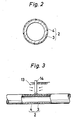
- Fig. 2 is a cross section perpendicular to the axis of a pipe member 2.
- Fig. 3 is a sectional view showing a state of a covering layer 4 damaged by an excavator 14 at a roadwork position 13.
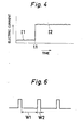
- Fig. 4 is a graph showing a change of electric current values with the passage of time which are found by an ammeter 8 of Fig. 1.
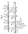
- Fig. 5 is an underground sectional view of another embodiment of the invention.
- Fig. 6 is a graph showing a change of the value of electric current flowing through the ammeter 8 of Fig. 5.
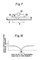
- Fig. 7 is an enlarged view showing a state of a voltmeter 22 connected to a buried object 2.
- Fig. 1 is an underground sectional view of an embodiment of the present invention.
- Fig. 2 is a cross section perpendicular to the axis of a pipe member 2.
- Fig. 3 is a sectional
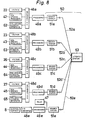
- Fig. 8 is a block diagram illustrating an electrical arrangement of the invention.
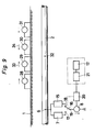
- Fig. 9 is a sectional view showing a system for detecting a damaged portion 32 of the pipe member 2.
- Fig. 10 is a graph showing an electric potential gradient of the earth surface along the longitudinal direction of the pipe member 2.
- Fig. 11 is an underground sectional view of still another embodiment of the invention.
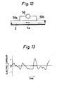
- Fig. 12 is an enlarged view showing a state of a voltmeter 58 connected to the buried object 2.
- Fig. 13 is a waveform diagram of electric currents la and lb.
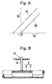
- Fig. 14 is a graph illustrating the relationship between values of electric currents la and Ib flowing at the same time.
- Fig. 15 is an enlarged sectional view showing the buried object 2 when it is damaged at a roadwork position 13.
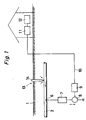
- Fig. 1 is a section view of an embodiment of the present invention.
- a pipe member 2 for transporting a fluid is buried under the ground 1.
- the section of the pipe member 2 perpendicular to the axis thereof is shown in Fig. 2.
- a covering layer 4 made of an electrically insulating material such as polyethylene. This layer 4 covers the steel pipe 3 over its entire periphery along its overall length.
- One terminal of an anticorrosive supply 7 is connected to the portion 6 of the pipe member 2.
- the other terminal of the power supply 7 is grounded through an ammeter 8.
- Current values measured by the ammeter 8 are sent to a receiver 11 through a transmitter 9 and a transmission line 10, and are displayed by a display device 12.
- An electric current flows through the steel pipe 3 of the pipe member 2 from the anticorrosive power supply 7, thus executing an electric anticorrosive performance for the pipe member 2.
- an anticorrosive electric current in the order of, for example, a microampere is measured by the ammeter 8. If small damage is present on the covering layer 4, an electric current in the order of, for example, a milliampere is measured by the ammeter 8.
- an anticorrosive electric current but also an electric current from the excavator 14 flow through the steel pipe 3.
- a value of the electric current detected by the ammeter 8 is a relatively small value I, at an ordinary time before the excavator 14 breaks the pipe member 2, but becomes a larger value 1 2 after the time t1. This means that the pipe member 2 is damaged at the time t1.
- the anticorrosive power supply 7 is employed in the embodiment discussed hereinbefore, there may be additionally disposed a detection power supply for flowing a larger electric current through the steel pipe 3 for detecting damage to the pipe member 2, and such detection power supply may be used only for periodical detection times, instead of the anticorrosive power supply 7.
- Fig. 5 is a section view of another embodiment of the present invention and like numerals are given to the corresponding parts.
- the respective one terminals of the anticorrosive power supply 7 and a detection power supply 15 are connected to the portion 6 in the pipe member 2 of the steel pipe 3.
- the other terminals of the power supplies 7 and 15 are respectively connected to the contacts 17 and 18 of a changeover switch 16.
- the common contact 19 of the changeover switch 16 is grounded through the ammeter 8.
- the changeover switch 16 is actuated by a relay circuit 47.
- Fig. 6 shows the wave form of an electric current detected by an ammeter 8.
- the common contact 19 of the changeover switch 16 is connected to the contact 17 for a period W1, so that an anticorrosive electric current flows through h the steel pipe 3 for such period W1.
- the common contact 19 of the changeover switch 16 is connected to the contact 18 for a period W2 by the relay circuit 47, so that a large electric current for damage detection is supplied from the detection power supply 15.
- the period W1 is for example about 10 minutes, while the period time W2 may be, for example, 5 seconds.
- the detection power supply 15 supplies a large electric current to the steel pipe 3 of the pipe member 2, thus facilitating detection of damage to the pipe member.
- a plurality of voltmeters 22 and 23 are connected to the steel pipe 3 of the pipe member 2 for measuring electric currents flowing through the pipe member 2 at both sides in the longitudinal direction thereof with respect to the power-connected portion 6.
- the terminals of the voltmeter 22 are connected to the steel pipe 3 of the pipe member 2 in longitudinally spaced relationship with each other.
- the voltmeter 23 is connected to the steel pipe 3, thereby measuring the value of electric current Ib flowing through the steel pipe 3.
- One or a plurality of voltmeters 26, 27, ... may be additionally connected to the steel pipe 3 of the pipe member 2.
- Fig. 8 shows a block diagram showing an electric arrangement. Respective output values from the voltmeters 22, 23, 26, and 27, the ammeter 8, and the soil specific resistance measuring means 42, 43, 44, and 45 are converted into digital values by an analogue-to-digital converter 48, and then sent to a data processing circuit 49 comprising a microcomputer.
- the data processing circuit 49 samples and measures voltages, electric currents, and soil specific resistances at a plurality of times for the period W2, so as to calculate and measure the average, and maximum and minimum values of the respective those values.
- Output data from the data processing circuit 49 are transmitted to a remote supervisory control device 50.
- This remote supervisory control device 50 comprises telemeter branch station 51 for transmitting output data from the data processing circuit 49, a transmission line 52, and a telemeter attended station 53 for performing a control operation.
- a signal from the telemeter attended station 53 causes the telemeter branch station 51 to switch the changeover switch 16 through the relay circuit 47.
- the reference numerals 48, 49, 51, and 52 designate the respective members in the gross with the additive small letters a, b, c, d, and e omitted.
- the value of an electric current la flowing through the steel pipe 3 measured by the voltmeter 22 is small and the value of an electric current flowing through the steel pipe 3 measured by the voltmeter 27 is also small.
- the value of the electric current Ib flowing through the steel pipe 3 measured by the voltmeter 23 is larger than la. This means that the pipe member 2 is being damaged at the right side in Fig. 5 or at the side of the voltmeter 23 which has detected the larger electric current, with respect to the power-connected portion 6.
- the electric current values measured by the voltmeters 26 and 27 are different from each other, it is readily understood that the damage is present on the pipe between these voltmeters 26 and 27.
- the pipe-ground electric potential difference on the ground corresponding to the damaged portion 14a of the pipe member 2 is indicated as V and the damage shape of the damaged portion 14a is a circle having a r.
- the damage area r is sufficiently larger than the covering layer thickness t, the damage area r or the damage size is approximated based on the following equation: where
- V undergoes a change with the passage of time
- the average of V for the period W2 is substantially constant regardless of time. Therefore, pipe-ground electric potential differences V1 and V2 are measured at suitable time intervals by measuring means 64 and 65 disposed at the pipe electric current measuring points at both sides with respect to the damaged portion 14a, and the average of V1 and V2 is used as V for the equation 2. Such calculation is made by the telemeter attended station 53. The period W2 during which such. sampling is made, is determined to be for example about 10 minutes.
- correction coefficient with respect to soil specific resistance p of the pipe member 2 at a given portion is represented by the average of correction coefficient with respect to soil specific resistance values p1 and p2 measured at the pipe electric current measuring points on both sides with respect to said given portion. Such calculation is made by the telemeter attended station 53.
- the telemeter attended station 53 compare the values of pipe electric currents corresponding to the voltages measured at the substantially same time by the voltmeters 22, 23, 26, and 27 with the respective adjacent ones, based on the results measured for respective periods W2 by the data processing circuit 49. As the consequence of such comparison, if the pipe electric currents 126 and 127 corresponding to the voltages measured by the voltmeters 26 and 27 are different from each other, the size of damage is calculated, measured, and displayed based on the difference i between the electric current values 126 and 127.
- calculated damage size depends on the contact area of the excavator 14 with the ground and is larger than the real size of the damage of the pipe member 2, if the excavator 14 remains contacted with the steel pipe 3 and is electrically connected thereto.
- the calculated damage size may be regarded as a value corresponding to the real size of the damage of the pipe member 2, for the practical purpose, in view of the fact that the electric current value i is averaged with the passage of time.
- Fig. 9 is a section view for precisely detecting the damage position of the pipe member 2. This embodiment is similar to the previous embodiment, and like reference numerals are given to the corresponding parts.
- a plurality of voltmeters 28, 29, 30, and 31 provided on the surface of the earth 1 at a plurality of positions in the longitudinal direction of the pipe member 2. Both the terminals of each of these voltmeters 28, 29, 30, and 31 are inserted into the ground 1 at different portions spaced apart along the longitudinal direction of the pipe member 2.
- An electric current is supplied to the steel pipe 3 of the pipe member 2 from either the anticorrosive power supply 7 or the detection power supply 15, by the changeover switch 16 operating changeover performance.
- the covering layer 4 is damaged at a portion 32 due to roadworks or the like, the voltages detected by the voltmeters 28, 29, 30, and 31 become opposite in polarity on both sides in the longitudinal direction of the pipe member 2 with respect to the damaged portions 32 of the pipe member 2, as shown by arrows 33 and 34 in Fig. 9.
- Electric potential difference or earth surface electric potential gradient per unit distance of the pipe member 2 in its longitudinal direction measured by the voltmeters 28, 29, 30, and 31, is as shown in Fig. 10. That is, the electric potential gradient becomes extremely small at the damaged portion 32. This means that the covering layer 4 is damaged at its portion exhibiting such small electric potential gradient.
- a larger electric current is supplied to the steel pipe 3 from the detection power supply 15, thus facilitating measurement utilizing the voltmeters 28, 29, 30, and 31.
- the present invention is not limited in application to the buried pipe member 2 discussed hereinbefore, but may be widely applied to buried objects covered with electrically insulating layers over the outer peripheries of conductive members.
- the detection power supply 15 used for detecting damage to a buried object may be an AC power supply. In such case, both the terminals of each of the voltmeters 28, 29, 30, and 31 are not necessarily inserted into the ground 1. Search coils may be disposed adjacent to the earth surface, and AC voltages induced by the coils may be measured.
- Fig. 11 is a sectional view of still another embodiment of the present invention.
- a pipe member 2 for transporting a fluid is buried under the ground 1. There is connected to portions 6a and 6b of the pipe member 2 one terminal of anticorrosive power supplies 7a and 7b, respectively, of which the other terminals are grounded.
- voltmeters 58 and 59 for measuring the values of electric currents la and Ib at the same time and comparing with each other through the steel pipe 3 at a plurality of positions (2 positions in this embodiment) among the power-connected portions 6a and 6b.
- the terminals 58a and 58b of the voltmeter 58 are connected to the steel pipe 3 in longitudinally spaced relationship with each other.
- the values of electric currents flowing through the steel pipe 3 measured by the voltmeters 58 and 59 are equal to each other, and undergo a change with the passage of time, for example, as shown in Fig. 13.
- a straight line 60 having a gradient of 45° is found as shown in Fig. 14.
- anticorrosive electric currents flowing through the steel pipe 3 of the pipe member 2 interact each other in view of the fact that a plurality of power supplies 7a and 7b are disposed, and such electric currents are greatly affected by stray electric currents in the ground.
- the state of such electric currents becomes as shown in Fig. 13.
- an accurate detection of damage to the covering layer 4 may be executed even if the electric currents la and Ib detected at the same time are greatly changed.
- damage detection power supplies for supplying greater electric currents than those of the anticorrosive power supplies 7a and 7b, are respectively provided for the power supplies 7a and 7b. Such damage detection power supplies are periodically switched over to the power supplies 7a and 7b, thus facilitating measurement utilizing the voltmeters 58 and 59.
- the present invention is not limited in application to the buried pipe member 2, but may be widely applied to longitudinally extending buried objects covered with electrically insulating layers over the outer peripheries of conductive members.
Abstract
Description
- This invention relates to a method and device for detecting damage to a buried object having an electrically insulating layer over a conductive member, which object is buried in an electrically conductive medium, such as the ground, comprising connecting one terminal of a power supply to said conductive member at a first position thereon; supplying electric current from said power supply to said conductive member and measuring along the buried object the flow of electrical current through the medium between the ground and said object to locate damage in said object by changes in the current flow.
- Such a method is known from USP 4,099,117. The method disclosed therein is specific for measuring a fracture in the insulating layer of a buried steel pipeline. To that effect, use is made of a plurality of electrodes situated in a plane perpendicular to the pipeline axis and when an opening occurs in the insulating layer, the current originating from an AC current source coupled to the pipeline will increase in the soil and provide an increase of the electric field which is collected by the electrodes and converted into peak signals.
- A drawback of this known method is that placing the electrodes in said mentioned plane perpendicular to the pipeline axis for detecting an opening in the insulated layer is rather elaborate.
- It is therefore an object of the present invention to provide a simple method for rapidly detecting damage to a buried object, and to provide a device for performing the method.
- The object is achieved in that the present invention is characterized by connecting the other terminal of said power supply to an ammeter which is grounded; sending signals from said ammeter to a display device to indicate damage to said buried object when electric current measured by said ammeter increases above a value which corresponds to a value of electric current measured by said ammeter when said object is not damaged, connecting both terminals of at least one first voltmeter to said conductive member on one side of said first position and connecting both terminals of at least one second voltmeter to said conductive member on the other side of said first position with said terminals of said at least one first voltmeter and said terminals of said at least one second voltmeter being spaced apart in the longitudinal direction of said buried object, connecting said at least one first voltmeter, said at least one second voltmeter and said ammeter to data processing means for analyzing output values from said at least one first voltmeter, said at least one second voltmeter and said ammeter when power is supplied to said conductive member from said power supply, and measuring and comparing the output values from said ammeter, said at least one first voltmeter and said at least one second voltmeter for detecting the presence of damage to said buried object and the relative location of any damage present as indicated by larger output values from said at least one first voltmeter or said at least one second voltmeter connected to said conductive member between said first position and a point of damage of said buried object.
- Furthermore, the present invention provides a method by connecting a soil specific resistance measuring means to the soil located at each position corresponding to said at least one first voltmeter and said at least one second voltmeter; connecting said soil specific measuring means to said data processing means for analyzing output values from said at least one first voltmeter, said at least one second voltmeter and said ammeter when power is supplied to said conductive member from said power supply, and measuring and comparing output values from said ammeter, said soil specific resistance measuring means, said at least one first voltmeter and said at least one second voltmeter for detecting the presence of damage to said buried object and the relative location of any damage present as indicated by larger output values from said at least one first voltmeter or said at least one second voltmeter connected to said conductive member between said first position and a point of damage of said buried object.
- The present invention moreover provides a method by connecting pipe-ground electric potential difference measuring means at each position corresponding to said at least one first voltmeter and said at least one second voltmeter; connecting said at least one first voltmeter, said at least one second voltmeter, said soil specific resistance measuring means, said pipe-ground electric potential difference measuring means and said ammeter to data processing means for analyzing output values from said at least one first voltmeter, said at least one second voltmeter and said ammeter when power is supplied to said conductive member from said power supply; and measuring and comparing output values from said ammeter, said soil specific resistance measuring means, said pipe-ground electric potential difference measuring means, said at least one first voltmeter and (each) said at least one second voltmeter for detecting the presence of damage to said buried object and the relative location of any damage present as indicated by larger output values from said at least one first voltmeter or said at least one second voltmeter connected to said conductive member between said first position and a point of damage of said buried object.
- For performing the method according to the present invention, there is provided a device according to
claim 4. - Fig. 1 is an underground sectional view of an embodiment of the present invention. Fig. 2 is a cross section perpendicular to the axis of a
pipe member 2. Fig. 3 is a sectional view showing a state of a coveringlayer 4 damaged by anexcavator 14 at aroadwork position 13. Fig. 4 is a graph showing a change of electric current values with the passage of time which are found by anammeter 8 of Fig. 1. Fig. 5 is an underground sectional view of another embodiment of the invention. Fig. 6 is a graph showing a change of the value of electric current flowing through theammeter 8 of Fig. 5. Fig. 7 is an enlarged view showing a state of avoltmeter 22 connected to a buriedobject 2. Fig. 8 is a block diagram illustrating an electrical arrangement of the invention. Fig. 9 is a sectional view showing a system for detecting a damagedportion 32 of thepipe member 2. Fig. 10 is a graph showing an electric potential gradient of the earth surface along the longitudinal direction of thepipe member 2. Fig. 11 is an underground sectional view of still another embodiment of the invention. Fig. 12 is an enlarged view showing a state of avoltmeter 58 connected to the buriedobject 2. Fig. 13 is a waveform diagram of electric currents la and lb. Fig. 14 is a graph illustrating the relationship between values of electric currents la and Ib flowing at the same time. Fig. 15 is an enlarged sectional view showing the buriedobject 2 when it is damaged at aroadwork position 13. - Fig. 1 is a section view of an embodiment of the present invention.
- A
pipe member 2 for transporting a fluid is buried under theground 1. The section of thepipe member 2 perpendicular to the axis thereof is shown in Fig. 2. - Applied to the exterior of a
steel pipe 3 of thepipe member 2 is a coveringlayer 4 made of an electrically insulating material such as polyethylene. Thislayer 4 covers thesteel pipe 3 over its entire periphery along its overall length. - One terminal of an
anticorrosive supply 7 is connected to theportion 6 of thepipe member 2. The other terminal of thepower supply 7 is grounded through anammeter 8. Current values measured by theammeter 8 are sent to areceiver 11 through atransmitter 9 and atransmission line 10, and are displayed by adisplay device 12. An electric current flows through thesteel pipe 3 of thepipe member 2 from theanticorrosive power supply 7, thus executing an electric anticorrosive performance for thepipe member 2. - Where there is no damage to the covering
layer 4, an anticorrosive electric current in the order of, for example, a microampere is measured by theammeter 8. If small damage is present on the coveringlayer 4, an electric current in the order of, for example, a milliampere is measured by theammeter 8. - It is assumed that a
metallic excavator 14 inserted into theground 1 at aroadwork place 13, breaks the coveringlayer 4 and comes in contact with thesteel pipe 3, as clearly shown in Fig. 3. In this case, not only an anticorrosive electric current but also an electric current from theexcavator 14 flow through thesteel pipe 3. As shown in Fig. 4, a value of the electric current detected by theammeter 8 is a relatively small value I, at an ordinary time before theexcavator 14 breaks thepipe member 2, but becomes alarger value 12 after the time t1. This means that thepipe member 2 is damaged at the time t1. - Although the
anticorrosive power supply 7 is employed in the embodiment discussed hereinbefore, there may be additionally disposed a detection power supply for flowing a larger electric current through thesteel pipe 3 for detecting damage to thepipe member 2, and such detection power supply may be used only for periodical detection times, instead of theanticorrosive power supply 7. - Fig. 5 is a section view of another embodiment of the present invention and like numerals are given to the corresponding parts.
- In this embodiment, the respective one terminals of the
anticorrosive power supply 7 and adetection power supply 15 are connected to theportion 6 in thepipe member 2 of thesteel pipe 3. The other terminals of thepower supplies contacts changeover switch 16. Thecommon contact 19 of thechangeover switch 16 is grounded through theammeter 8. Thechangeover switch 16 is actuated by arelay circuit 47. - Fig. 6 shows the wave form of an electric current detected by an
ammeter 8. Thecommon contact 19 of thechangeover switch 16 is connected to thecontact 17 for a period W1, so that an anticorrosive electric current flows through h thesteel pipe 3 for such period W1. - The
common contact 19 of thechangeover switch 16 is connected to thecontact 18 for a period W2 by therelay circuit 47, so that a large electric current for damage detection is supplied from thedetection power supply 15. The period W1 is for example about 10 minutes, while the period time W2 may be, for example, 5 seconds. For the period W2, thedetection power supply 15 supplies a large electric current to thesteel pipe 3 of thepipe member 2, thus facilitating detection of damage to the pipe member. - In Fig. 5, a plurality of
voltmeters steel pipe 3 of thepipe member 2 for measuring electric currents flowing through thepipe member 2 at both sides in the longitudinal direction thereof with respect to the power-connectedportion 6. As shown in Fig. 7, the terminals of thevoltmeter 22 are connected to thesteel pipe 3 of thepipe member 2 in longitudinally spaced relationship with each other. - An electric current la flowing through the
steel pipe 3 is expressed by the following equation:
- E=voltage measured by the
voltmeter 22, - I=distance in meter between the
portions steel pipe 3 connected to thevoltmeter 22. Such distance is for example 30 m, - R=resistance per meter of the
steel pipe 3. - Likewise, the
voltmeter 23 is connected to thesteel pipe 3, thereby measuring the value of electric current Ib flowing through thesteel pipe 3. One or a plurality ofvoltmeters steel pipe 3 of thepipe member 2. - There are provided means for measuring soil
specific resistance voltmeters electric potential difference voltmeters - Fig. 8 shows a block diagram showing an electric arrangement. Respective output values from the
voltmeters ammeter 8, and the soil specific resistance measuring means 42, 43, 44, and 45 are converted into digital values by an analogue-to-digital converter 48, and then sent to a data processing circuit 49 comprising a microcomputer. The data processing circuit 49 samples and measures voltages, electric currents, and soil specific resistances at a plurality of times for the period W2, so as to calculate and measure the average, and maximum and minimum values of the respective those values. Output data from the data processing circuit 49 are transmitted to a remotesupervisory control device 50. - This remote
supervisory control device 50 comprises telemeter branch station 51 for transmitting output data from the data processing circuit 49, a transmission line 52, and a telemeter attendedstation 53 for performing a control operation. A signal from the telemeter attendedstation 53 causes the telemeter branch station 51 to switch thechangeover switch 16 through therelay circuit 47. - The reference numerals 48, 49, 51, and 52 designate the respective members in the gross with the additive small letters a, b, c, d, and e omitted.
- It is assumed that the
metallic excavator 14 inserted into theground 1 at theroadwork place 13, breaks thecovering layer 4 of thepipe member 2 and comes in contact with thesteel pipe 3. In this case, a large electric current flows through thesteel pipe 3 from theexcavator 14. Such electric current exhibits a large value between theexcavator 14 and the power-connectedportion 6 of thepipe member 2, while an electric current flowing through the other portions of thesteel pipe 3 is small. That is, the values of electric currents Ib flowing through thesteel pipe 3 measured at the same time by thevoltmeters steel pipe 3 measured by thevoltmeter 22 is small and the value of an electric current flowing through thesteel pipe 3 measured by thevoltmeter 27 is also small. When a comparison is made between the electric currents la and Ib flowing through thesteel pipe 3 measured by thevoltmeters pipe member 2 in the longitudinal direction thereof with respect to the power-connectedportion 6, the value of the electric current Ib flowing through thesteel pipe 3 measured by thevoltmeter 23 is larger than la. This means that thepipe member 2 is being damaged at the right side in Fig. 5 or at the side of thevoltmeter 23 which has detected the larger electric current, with respect to the power-connectedportion 6. Moreover, since the electric current values measured by thevoltmeters voltmeters - It is assumed that the pipe-ground electric potential difference on the ground corresponding to the damaged
portion 14a of thepipe member 2 is indicated as V and the damage shape of the damagedportion 14a is a circle having a r. Where the damage area r is sufficiently larger than the covering layer thickness t, the damage area r or the damage size is approximated based on the following equation:
- p=correction coefficient with respect to soil specific resistance of the damaged
portion 14a, - i=electric current flowing through the
steel pipe 3 at the damagedportion 14a, - k=proportional constant.
- Although V undergoes a change with the passage of time, the average of V for the period W2 is substantially constant regardless of time. Therefore, pipe-ground electric potential differences V1 and V2 are measured at suitable time intervals by measuring
means portion 14a, and the average of V1 and V2 is used as V for theequation 2. Such calculation is made by the telemeter attendedstation 53. The period W2 during which such. sampling is made, is determined to be for example about 10 minutes. - p varies with the place and the weather. Where the pipe electric current measuring distance is determined to be a suitable one, for example several kilometers, p varies with only the weather. If, therefore, soil specific resistance is measured at each of the pipe electric current measuring points, correction coefficient with respect to soil specific resistance p of the
pipe member 2 at a given portion is represented by the average of correction coefficient with respect to soil specific resistance values p1 and p2 measured at the pipe electric current measuring points on both sides with respect to said given portion. Such calculation is made by the telemeter attendedstation 53. - The electric current i is found from the following equation:

- 126=electric current flowing through the
steel pipe 3 corresponding to the voltage measured by thevoltmeter 26 at one side with respect to thedamage portion 14a, - 127=electric current flowing through the
steel pipe 3 corresponding to the voltage measured by thevoltmeter 27 at the other side with respect to thedamage portion 14a. - The telemeter attended
station 53 compare the values of pipe electric currents corresponding to the voltages measured at the substantially same time by thevoltmeters electric currents voltmeters current values - Thus calculated damage size depends on the contact area of the
excavator 14 with the ground and is larger than the real size of the damage of thepipe member 2, if theexcavator 14 remains contacted with thesteel pipe 3 and is electrically connected thereto. However, such contact of theexcavator 14 with thesteel pipe 3 is generally made for a short period of time, for example for a moment. In this connection, the calculated damage size may be regarded as a value corresponding to the real size of the damage of thepipe member 2, for the practical purpose, in view of the fact that the electric current value i is averaged with the passage of time. - Fig. 9 is a section view for precisely detecting the damage position of the
pipe member 2. This embodiment is similar to the previous embodiment, and like reference numerals are given to the corresponding parts. - A plurality of
voltmeters earth 1 at a plurality of positions in the longitudinal direction of thepipe member 2. Both the terminals of each of thesevoltmeters ground 1 at different portions spaced apart along the longitudinal direction of thepipe member 2. An electric current is supplied to thesteel pipe 3 of thepipe member 2 from either theanticorrosive power supply 7 or thedetection power supply 15, by thechangeover switch 16 operating changeover performance. - If the
covering layer 4 is damaged at aportion 32 due to roadworks or the like, the voltages detected by thevoltmeters pipe member 2 with respect to the damagedportions 32 of thepipe member 2, as shown byarrows pipe member 2 in its longitudinal direction measured by thevoltmeters portion 32. This means that thecovering layer 4 is damaged at its portion exhibiting such small electric potential gradient. - In this embodiment also, a larger electric current is supplied to the
steel pipe 3 from thedetection power supply 15, thus facilitating measurement utilizing thevoltmeters - The present invention is not limited in application to the buried
pipe member 2 discussed hereinbefore, but may be widely applied to buried objects covered with electrically insulating layers over the outer peripheries of conductive members. - The
detection power supply 15 used for detecting damage to a buried object may be an AC power supply. In such case, both the terminals of each of thevoltmeters ground 1. Search coils may be disposed adjacent to the earth surface, and AC voltages induced by the coils may be measured. - Fig. 11 is a sectional view of still another embodiment of the present invention.
- A
pipe member 2 for transporting a fluid is buried under theground 1. There is connected toportions pipe member 2 one terminal ofanticorrosive power supplies - There are provided
voltmeters steel pipe 3 at a plurality of positions (2 positions in this embodiment) among the power-connectedportions - As shown in Fig. 12, the
terminals voltmeter 58 are connected to thesteel pipe 3 in longitudinally spaced relationship with each other. - An electric current la flowing through the
steel pipe 3 of thepipe member 2, is expressed by the following equation:
- E=voltage measured by the
voltmeter 8, - I=distance in meter between the connection portions 8a and 8b,
- R=resistance per meter of the
steel pipe 3. - Likewise, the
voltmeter 59 is connected to thesteel pipe 3, thus measuring an electric current Ib flowing through thesteel pipe 3. - Where the
covering layer 4 of thepipe member 2 is not damaged, the values of electric currents flowing through thesteel pipe 3 measured by thevoltmeters straight line 60 having a gradient of 45° is found as shown in Fig. 14. - It is assumed that the
metallic excavator 4 inserted in theground 1 at theroadwork position 13 between thevoltmeters covering layer 14 of thepipe member 2 and makes contact with thesteel pipe 3. In this case, a large electric current flows through thesteel pipe 3 from theexcavator 14. Such electric current branches off at different rates to the right- and left-sides of thesteel pipe 3 with respect to theroadwork position 13 in Figs. 11 and 15. Therefore the values of electric currents la and Ib found at the same time by thevoltmeters line 61 moved in parallel from theline 60 passing through theorigin 0. Thus it is understood that thepipe member 2 is damaged between its portions connected to thevoltmeters voltmeters - In this embodiment, anticorrosive electric currents flowing through the
steel pipe 3 of thepipe member 2 interact each other in view of the fact that a plurality ofpower supplies covering layer 4 is damaged, by discriminating the respective levels of the current values I and lb. However, in the above-mentioned embodiment, an accurate detection of damage to thecovering layer 4 may be executed even if the electric currents la and Ib detected at the same time are greatly changed. - According to yet another embodiment of the present invention, damage detection power supplies for supplying greater electric currents than those of the
anticorrosive power supplies power supplies power supplies voltmeters - The present invention is not limited in application to the buried
pipe member 2, but may be widely applied to longitudinally extending buried objects covered with electrically insulating layers over the outer peripheries of conductive members.
Claims (5)
Applications Claiming Priority (1)
| Application Number | Priority Date | Filing Date | Title |
|---|---|---|---|
| PCT/JP1983/000110 WO1984004166A1 (en) | 1983-04-12 | 1983-04-12 | Method and device for detecting damage to buried object |
Publications (3)
| Publication Number | Publication Date |
|---|---|
| EP0148267A1 EP0148267A1 (en) | 1985-07-17 |
| EP0148267A4 EP0148267A4 (en) | 1985-09-18 |
| EP0148267B1 true EP0148267B1 (en) | 1989-03-15 |
Family
ID=13789979
Family Applications (1)
| Application Number | Title | Priority Date | Filing Date |
|---|---|---|---|
| EP83901107A Expired EP0148267B1 (en) | 1983-04-12 | 1983-04-12 | Method and device for detecting damage to buried object |
Country Status (4)
| Country | Link |
|---|---|
| US (1) | US4689552A (en) |
| EP (1) | EP0148267B1 (en) |
| NL (1) | NL8320099A (en) |
| WO (1) | WO1984004166A1 (en) |
Families Citing this family (11)
| Publication number | Priority date | Publication date | Assignee | Title |
|---|---|---|---|---|
| DE3721205A1 (en) * | 1987-06-26 | 1989-01-05 | Pfaudler Werke Ag | METHOD FOR DETERMINING DAMAGE TO A CORROSION PROTECTIVE LAYER AND MEASURING DEVICE FOR CARRYING OUT THIS METHOD |
| IT1244473B (en) * | 1990-12-14 | 1994-07-15 | Eniricerche Spa | DEVICE AND PROCEDURE FOR REAL-TIME MONITORING OF ACCIDENTAL DAMAGES OF THE PROTECTIVE COATING OF UNDERGROUNDED OR IMMERSED METALLIC CONDUCT OR STRUCTURES |
| US5378991A (en) * | 1992-05-27 | 1995-01-03 | Anderson; Thomas F. | Detecting degradation of non-conductive inert wall layers in fluid containers |
| US6650125B1 (en) | 2001-12-06 | 2003-11-18 | The United States Of America As Represented By The Administrator Of The National Aeronautics And Space Administration | Leak and pipe detection method and system |
| KR100660156B1 (en) * | 2005-12-26 | 2006-12-20 | 한국가스공사연구개발원 | Wireless third-party damage monitoring system using gas pipe as wave guide |
| KR100720737B1 (en) | 2005-12-26 | 2007-05-22 | 한국가스공사연구개발원 | Third-party damage monitoring system by support sensor and the method thereof |
| KR100660157B1 (en) | 2005-12-26 | 2006-12-20 | 한국가스공사연구개발원 | Third-party damage monitoring system by closed loop |
| IE20090304A1 (en) * | 2008-04-16 | 2009-10-28 | Fmc Tech Ltd | A system and method for locating line faults in a medium voltage network |
| CN104246485B (en) * | 2012-04-24 | 2017-02-22 | 英派尔科技开发有限公司 | Sensor for detecting damage to an object |
| US10370909B2 (en) | 2014-08-04 | 2019-08-06 | Halliburton Energy Services, Inc. | Enhanced slickline |
| US9977066B2 (en) * | 2015-04-15 | 2018-05-22 | Cooper Technologies Company | Systems, methods, and devices for diagnosing integrity of electrical conductor-carrying systems |
Family Cites Families (9)
| Publication number | Priority date | Publication date | Assignee | Title |
|---|---|---|---|---|
| US3405356A (en) * | 1966-12-09 | 1968-10-08 | Texaco Inc | System including two pairs of voltage electrodes for detecting discontinuities in insulation coatings on conductive conduit |
| JPS4939942B1 (en) * | 1969-11-19 | 1974-10-30 | ||
| US3800217A (en) * | 1971-09-23 | 1974-03-26 | Lowrance Electronics Mfg | Pipeline including means of indicating the existence of and location of a leak |
| JPS4939942A (en) * | 1972-08-25 | 1974-04-15 | ||
| US3916298A (en) * | 1973-07-11 | 1975-10-28 | Scott Allison E | System utilizing galvanic potentials for detecting buried conductive structures |
| US4063161A (en) * | 1975-04-14 | 1977-12-13 | Joslyn Mfg. And Supply Co. | Buried cable fault locator with earth potential indicator and pulse generator |
| US4099117A (en) * | 1976-04-26 | 1978-07-04 | Dick Gaut | Method and apparatus for measuring the quality of insulation on a buried pipeline and the quantity of metal oxide present at breaks in the insulation |
| JPS5863845A (en) * | 1981-10-12 | 1983-04-15 | Osaka Gas Co Ltd | Damage detecting method for underground substance |
| JPS5863844A (en) * | 1981-10-12 | 1983-04-15 | Osaka Gas Co Ltd | Damage detecting method for underground substance |
-
1983
- 1983-04-12 US US06/882,012 patent/US4689552A/en not_active Expired - Fee Related
- 1983-04-12 EP EP83901107A patent/EP0148267B1/en not_active Expired
- 1983-04-12 WO PCT/JP1983/000110 patent/WO1984004166A1/en active IP Right Grant
- 1983-04-12 NL NL8320099A patent/NL8320099A/en not_active Application Discontinuation
Also Published As
| Publication number | Publication date |
|---|---|
| EP0148267A4 (en) | 1985-09-18 |
| EP0148267A1 (en) | 1985-07-17 |
| WO1984004166A1 (en) | 1984-10-25 |
| US4689552A (en) | 1987-08-25 |
| NL8320099A (en) | 1985-03-01 |
Similar Documents
| Publication | Publication Date | Title |
|---|---|---|
| US5828219A (en) | Method of detecting faults in the insulation layer of an insulated concealed conductor | |
| EP0148267B1 (en) | Method and device for detecting damage to buried object | |
| US4947469A (en) | Resistive fault location method and device for use on electrical cables | |
| CA1083528A (en) | Method and apparatus for monitoring a cathodically protected corrodible hollow member | |
| EP0164838B1 (en) | Event location using a locating member containing discrete impedances | |
| US5654642A (en) | System and method of use for conducting a neutral corrosion survey | |
| US4942361A (en) | Method and apparatus for determining earth resistivities in the presence of extraneous earth currents | |
| US4357573A (en) | Method of surveying sub-sea pipeline | |
| RU2718711C1 (en) | Method of diagnosing insulating coating defects of pipelines | |
| Dzhala et al. | Information Technology of Surveys and Diagnostics of Underground Pipelines | |
| EP0693681B1 (en) | Apparatus and methods for measuring the ohmic-drop-free potential and for coating integrity evaluation in presence of stray currents | |
| RU2641794C1 (en) | Method for determination of technical state of underground pipeline insulating coating | |
| SU1335899A1 (en) | Method of determining insulation resistance of underground pipeline | |
| RU2781137C1 (en) | Method for determining the integrity of pipeline protective casings at intersections with roads and railways | |
| US2931975A (en) | Fault location in electrical cables | |
| JPH0231342B2 (en) | ||
| JP2001116714A (en) | Apparatus and method for judging damage of coated embedded metal conductor | |
| Mariscotti | Methods and instruments for stray current verification in DC rapid transit and railway systems | |
| Walton | ACVG or DCVG-Does It Matter? Absolutely It Does. | |
| SU998584A1 (en) | Method for determining degree of protection of pipelines | |
| RU2576979C1 (en) | Method for detection of break in extended anode beds | |
| JPH0441786B2 (en) | ||
| JPH09189505A (en) | Method and device for determining damaged location and damage degree of coated steel pipe | |
| SU938214A1 (en) | Device for locating damage of pipe-line insulation | |
| JPH08145934A (en) | Monitoring method and device for damage degree of clad steel pipe |
Legal Events
| Date | Code | Title | Description |
|---|---|---|---|
| PUAI | Public reference made under article 153(3) epc to a published international application that has entered the european phase |
Free format text: ORIGINAL CODE: 0009012 |
|
| 17P | Request for examination filed |
Effective date: 19850423 |
|
| AK | Designated contracting states |
Kind code of ref document: A1 Designated state(s): FR Designated state(s): FR |
|
| 17Q | First examination report despatched |
Effective date: 19861208 |
|
| GRAA | (expected) grant |
Free format text: ORIGINAL CODE: 0009210 |
|
| AK | Designated contracting states |
Kind code of ref document: B1 Designated state(s): FR |
|
| ET | Fr: translation filed | ||
| PLBE | No opposition filed within time limit |
Free format text: ORIGINAL CODE: 0009261 |
|
| STAA | Information on the status of an ep patent application or granted ep patent |
Free format text: STATUS: NO OPPOSITION FILED WITHIN TIME LIMIT |
|
| 26N | No opposition filed | ||
| PGFP | Annual fee paid to national office [announced via postgrant information from national office to epo] |
Ref country code: FR Payment date: 19900529 Year of fee payment: 8 |
|
| PG25 | Lapsed in a contracting state [announced via postgrant information from national office to epo] |
Ref country code: FR Effective date: 19911230 |
|
| REG | Reference to a national code |
Ref country code: FR Ref legal event code: ST |