EP1037001A2 - Apparatus for cooling the power electronis of a refrigeration compressor drive - Google Patents
Apparatus for cooling the power electronis of a refrigeration compressor drive Download PDFInfo
- Publication number
- EP1037001A2 EP1037001A2 EP00200682A EP00200682A EP1037001A2 EP 1037001 A2 EP1037001 A2 EP 1037001A2 EP 00200682 A EP00200682 A EP 00200682A EP 00200682 A EP00200682 A EP 00200682A EP 1037001 A2 EP1037001 A2 EP 1037001A2
- Authority
- EP
- European Patent Office
- Prior art keywords
- heat sink
- temperature
- refrigerant
- cooling
- valve
- Prior art date
- Legal status (The legal status is an assumption and is not a legal conclusion. Google has not performed a legal analysis and makes no representation as to the accuracy of the status listed.)
- Granted
Links
Images


Classifications
-
- F—MECHANICAL ENGINEERING; LIGHTING; HEATING; WEAPONS; BLASTING
- F25—REFRIGERATION OR COOLING; COMBINED HEATING AND REFRIGERATION SYSTEMS; HEAT PUMP SYSTEMS; MANUFACTURE OR STORAGE OF ICE; LIQUEFACTION SOLIDIFICATION OF GASES
- F25B—REFRIGERATION MACHINES, PLANTS OR SYSTEMS; COMBINED HEATING AND REFRIGERATION SYSTEMS; HEAT PUMP SYSTEMS
- F25B5/00—Compression machines, plants or systems, with several evaporator circuits, e.g. for varying refrigerating capacity
- F25B5/02—Compression machines, plants or systems, with several evaporator circuits, e.g. for varying refrigerating capacity arranged in parallel
-
- B—PERFORMING OPERATIONS; TRANSPORTING
- B01—PHYSICAL OR CHEMICAL PROCESSES OR APPARATUS IN GENERAL
- B01D—SEPARATION
- B01D46/00—Filters or filtering processes specially modified for separating dispersed particles from gases or vapours
- B01D46/0002—Casings; Housings; Frame constructions
- B01D46/0005—Mounting of filtering elements within casings, housings or frames
-
- F—MECHANICAL ENGINEERING; LIGHTING; HEATING; WEAPONS; BLASTING
- F04—POSITIVE - DISPLACEMENT MACHINES FOR LIQUIDS; PUMPS FOR LIQUIDS OR ELASTIC FLUIDS
- F04B—POSITIVE-DISPLACEMENT MACHINES FOR LIQUIDS; PUMPS
- F04B39/00—Component parts, details, or accessories, of pumps or pumping systems specially adapted for elastic fluids, not otherwise provided for in, or of interest apart from, groups F04B25/00 - F04B37/00
- F04B39/06—Cooling; Heating; Prevention of freezing
-
- F—MECHANICAL ENGINEERING; LIGHTING; HEATING; WEAPONS; BLASTING
- F25—REFRIGERATION OR COOLING; COMBINED HEATING AND REFRIGERATION SYSTEMS; HEAT PUMP SYSTEMS; MANUFACTURE OR STORAGE OF ICE; LIQUEFACTION SOLIDIFICATION OF GASES
- F25B—REFRIGERATION MACHINES, PLANTS OR SYSTEMS; COMBINED HEATING AND REFRIGERATION SYSTEMS; HEAT PUMP SYSTEMS
- F25B31/00—Compressor arrangements
- F25B31/006—Cooling of compressor or motor
Definitions
- This invention relates to method and apparatus for cooling of the electronics of a variable frequency drive associated with a refrigerant compressor.
- VFD variable frequency drives
- the heat sink is usually in the form of a relatively large block of material having good heat transfer and thermal inertia characteristics.
- a flow passage is formed in the block and coolant is circulated through the passage which absorbs excess heat and carries it out of the system.
- a closed loop refrigeration system that includes a condenser, an evaporator, and a compressor connected in series by refrigerant lines and an expansion means in one of the refrigerant lines for throttling refrigerant moving between the condenser and the evaporator from a high pressure to a lower pressure.
- a variable frequency drive is associated with the compressor that contains heat producing power electronic components in the form of insulated gate bipolar transistors that require cooling.
- the power electronic components are mounted in heat transfer relation wit a block of material having good heat transfer characteristics. The block acts as a heat sink to draw heat away from the power electronic components.
- a flow circuit is arranged to pass refrigerant from the system condenser to the inlet of the system compressor through the heat sink.
- An expansion valve is mounted in the flow circuit which controls the expansion of refrigerant moving through the circuit, thus providing cooling to the heat sink and the electronic components thereon.
- a refrigeration system that utilizes the Carnot refrigeration cycle that includes a series of refrigerant lines 12 that operatively connects the various system components.
- the system further includes a condenser 13 that is connected to the outlet side of a compressor 15 by means of a refrigerant line 12.
- the condenser is, in turn, connected in series with an evaporator 17, the outlet of which is connected via a refrigerant line to the inlet side of the compressor to complete the system loop.
- An expansion device 20 is mounted in the refrigeration line between the condenser and the evaporator which expands high pressure refrigerant leaving the condenser to a lower temperature and pressure.
- the expansion device can be any one of many such devices, such as a throttling valve or capillary tube of the types that are well known and used in the art.
- a substance to be chilled is circulated through the evaporator in heat transfer relationship with the low temperature refrigerant.
- the refrigerant, as it absorbs heat in the chilling process is evaporated at a relatively low pressure and the refrigerant vapor is then delivered to the compressor inlet for recirculation through the system.
- the compressor motor is equipped with a variable frequency drive (VFD) 25 that controls the motor speed.
- VFD variable frequency drive
- the drive is shown in phantom outline in Fig. 1.
- the VFD typically contains power electronics that require cooling in order for the drive to operate under optimum conditions over the operating range of the system.
- the power electronic components requiring cooling are generally insulated gate bipolar transistors (IGBT) that are depicted schematically at 27 in the drawings.
- IGBT insulated gate bipolar transistors
- the power electronic components have heretofore been cooled by placing them in heat transfer relation with a heat sink and circulating cooling water. This type of cooling system is rather complex, requires a good deal of space, and is difficult to control.
- the power electronic components of the VFD are mounted directly upon a heat sink 30 that forms part of what is herein referred to as the VFD evaporator 29.
- the heat sink is fabricated from a block of material that has a high coefficient of thermal conductivity such that the heat energy generated by the power electronic components is rapidly drawn away from and absorbed into the heat sink.
- An internal flow channel 32 is mounted within the block of material. The channel follows a tortuous path of travel through the block of material to provide for a maximum amount of contact area between the channel and the heat sink.
- the flow channel can be a length of copper tubing or the like that is embedded in the heat sink and which has an inlet at 33 and an outlet at 34.
- the inlet 33 to the internal flow channel is connected to the refrigerant outlet 35 of the system condenser by a supply line 36.
- the outlet of the flow channel is connected to the compressor inlet by a discharge line 39.
- a control valve, generally referenced 40 is contained in the supply line through which refrigerant is throttled from the higher condenser pressure down to a lower pressure thereby providing low temperature refrigerant to the heat sink for cooling the power electronic components.
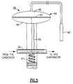
- the control valve 40 is shown in greater detail in Fig. 5.
- the valve includes a sensor probe 42 that is embedded in the heat sink as close as practicable to the power electronic components that will best reference the operating temperature.
- the valve may be a temperature control valve which responds to the temperature sensed by the probe or a temperature expansion valve which responds to pressure changes at the probe produced by temperature changes in the heat sink.
- the valve is a temperature expansion valve that includes a diaphragm 43 mounted inside a housing 44. Based upon the temperature of the heat sink, the bulb pressure changes which, in turn, sets a pressure on the high side chamber 45 of the diaphragm.
- the pressure on the low side chamber of the diaphragm 46 is determined by a preset adjustable spring 47 and an equalizing port 49 that extends between the low pressure side of the chamber and the low pressure side of the valve body 50.
- the pressure balance across the diaphragm of the valve locates the valve body within the valve passage and thus controls the amount of cooling provided to the heat sink.
- the heat sink temperature is held within a range of between 90° and 140°.
- the heat sink with the flow channel passing therethrough acts as a refrigerant evaporator with regard to the VFD to provide closely controlled cooling to the power electronic components by utilizing the refrigeration cycle to remove heat from the VFD.
- the heat transferred to the refrigerant in the VFD evaporator is moved by the system compressor to the system condenser where it is rejected into the condenser cooling loop.
- Fig. 2 depicts a further embodiment of the invention wherein like components described with reference to Fig. 1 are identified with the same reference numbers.
- the discharge line 39 of the VFD evaporator is connected into the system evaporator 17 and combined with refrigerant being processed through the evaporator.
- the valve sensor 42 is shown mounted upon the discharge line of the VFD evaporator rather than embedded in the heat sink. The sensor feeds back temperature information to the control valve 40 which, in turn, sets the positioning of the valve body in response to the sensed refrigerant temperature to hold the sink temperature within the desired operating range needed to cool the power electronic components.
- Fig. 3 there is shown a still further embodiment of the invention where again like numbers are used to identify like previously identified components.
- the control valve 40 is mounted in the discharge line of the VFD evaporator 29 which, in this case, is connected directly to the compressor inlet.
- the discharge line may alternatively be connected directly to the system.
- the temperature sensor 42 is embedded in the heat sink 30 of the VFD evaporator and provides temperature related information to the control valve.
- the temperature of the refrigerant leaving the system condenser is below 140°F so that the refrigerant shunted to the VFD evaporator is well within the desired heat sink temperature range required for cooling the power electronic components.
- Fig. 4 illustrates a still further embodiment of the invention wherein like numbers are again used to identify previously above-identified components.
- part of the refrigerant leaving the system condenser is expanded into the VFD evaporator 29 through a temperature control valve 40.
- a temperature sensor 42 is again embedded in the heat sink 30 and provides temperature related information to a microprocessor 50 that is programmed to process the data and send a control signal to the valve.
- Other system related information can also be sent to the microprocessor which can be additionally processed to arrive at a desired valve setting to provide cooling to the power electronics at a minimum of expense to the system's overall performance.
- the present invention is a simple yet effective solution to cooling the power electric components of a variable frequency drive for a refrigerant compressor.
- the present system eliminates the complexities of the more traditional water cooling systems, is easier to install, and provides for greater control over the cooling process.
- the present system because of its efficiency, also allows for greater use of the power electronics having a greater capacity than those presently found in the prior art used in the compressor drive of a refrigeration system.
- the present invention improves the cooling of the power electronics of a variable frequency drive used to control a refrigerant compressor.
- a still further feature of the present invention is to reduce the amount of space required by cooling equipment for the variable frequency drive of the refrigeration system compressor.
- Another feature of the present invention is to more reliably control the cooling of the power electronic components of the variable frequency drive of the refrigeration system compressor.
- Still another feature of the present invention is the provision of refrigerant cooling to the power electronics of the variable frequency drive of the refrigeration system compressor.
Landscapes
- Engineering & Computer Science (AREA)
- Mechanical Engineering (AREA)
- General Engineering & Computer Science (AREA)
- Physics & Mathematics (AREA)
- Thermal Sciences (AREA)
- Chemical & Material Sciences (AREA)
- Chemical Kinetics & Catalysis (AREA)
- Cooling Or The Like Of Semiconductors Or Solid State Devices (AREA)
- Cooling Or The Like Of Electrical Apparatus (AREA)
- Devices That Are Associated With Refrigeration Equipment (AREA)
- Compressor (AREA)
- Control Of Temperature (AREA)
Abstract
Description
Claims (16)
- Cooling apparatus for the power electronics of a variable frequency drive used to control the motor of a compressor in a refrigeration system that is characterized bya refrigeration system that further includes a compressor, a condenser, and an evaporator connected in series by refrigerant lines and an expansion means in one of said lines for throttling refrigerant moving between the condenser and the evaporator,a variable frequency drive means connected to the compressor motor, said drive means containing power electronic components that require cooling,a circuit for shunting a portion of the refrigerant from the system condenser to the compressor inlet,a variable frequency drive evaporator mounted in said circuit that is in heat transfer relation with the power electronics components of the variable frequency drive;a control valve in said circuit for expanding the refrigerant moving through said circuit from the system condenser pressure to the compressor inlet pressure whereby said power electronic components are cooled.
- The apparatus of claim 1 wherein said variable frequency drive evaporator includes a heat sink formed of a block of material having a high coefficient of thermal conductivity through which said flow channel passes and wherein said power electronic components are mounted in heat transfer relation with said heat sink.
- The apparatus of claim 1 that further includes a temperature probe for providing heat sink related temperature information to the said valve whereby the valve is opened and closed in response to the sensed temperature.
- The apparatus of claim 3 wherein said temperature probe is embedded in said heat sink.
- The apparatus of claim 3 wherein said sensor is mounted in said flow circuit downstream from the heat sink.
- The apparatus of claim 2 wherein said control valve is a temperature expansion valve and further includes a temperature probe for providing pressure information to the valve based upon the temperature of the heat sink.
- The apparatus of claim 6 wherein said probe is embedded in said heat sink.
- The apparatus of claim 2 wherein said control valve is located upon the upstream side of said heat sink.
- The apparatus of claim 2 wherein said control valve is located on the downstream side of the heat sink.
- The apparatus of claim 3 that further includes a microprocessor that is arranged to accept input data from the probe and provides an output control signal to said valve for holding the heat sink temperature within a desired temperature range.
- A method of cooling the power electronic components of a variable frequency drive (VFD) used to control the motor of compressor in a refrigeration system that is characterized by the steps of:mounting the power electronic components of the VFD in heat transfer relation with a heat sink.bringing refrigerant drawn from the refrigeration condenser in heat transfer relation with heat sink,expanding the refrigerant drawn from the condenser pressure down to a lower pressure to maintain the heat sink temperature within a desired range.
- The method of claim 11 that includes the further step of discharging refrigerant leaving said heat sink into the system compressor inlet.
- The method of claim 11 that includes the further step of discharging refrigerant leaving said heat sink into the system evaporator.
- The method of claim 11 that further includes the step of expanding said refrigerant through a control valve prior to bringing said refrigerant into heat transfer relation with said heat sink.
- The method of claim 14 that includes the further step of sensing the temperature of said heat sink and position said control valve in response to said sensed temperature.
- The method of claim 14 that includes the further step sensing the temperature of said heat sink, providing the sensed temperature data to a microprocessor for processing and providing an output signal from said processor to said control valve for maintaining the temperature of said heat sink within a desired range.
Applications Claiming Priority (2)
| Application Number | Priority Date | Filing Date | Title |
|---|---|---|---|
| US268573 | 1999-03-15 | ||
| US09/268,573 US6116040A (en) | 1999-03-15 | 1999-03-15 | Apparatus for cooling the power electronics of a refrigeration compressor drive |
Publications (3)
| Publication Number | Publication Date |
|---|---|
| EP1037001A2 true EP1037001A2 (en) | 2000-09-20 |
| EP1037001A3 EP1037001A3 (en) | 2000-10-04 |
| EP1037001B1 EP1037001B1 (en) | 2004-09-15 |
Family
ID=23023591
Family Applications (1)
| Application Number | Title | Priority Date | Filing Date |
|---|---|---|---|
| EP00200682A Expired - Lifetime EP1037001B1 (en) | 1999-03-15 | 2000-02-28 | Apparatus for cooling the power electronis of a refrigeration compressor drive |
Country Status (11)
| Country | Link |
|---|---|
| US (1) | US6116040A (en) |
| EP (1) | EP1037001B1 (en) |
| JP (1) | JP2000283569A (en) |
| KR (1) | KR100351599B1 (en) |
| CN (1) | CN1134628C (en) |
| AU (1) | AU766412B2 (en) |
| DE (1) | DE60013666T2 (en) |
| ES (1) | ES2223388T3 (en) |
| MY (1) | MY125343A (en) |
| SG (1) | SG84572A1 (en) |
| TW (1) | TWM267436U (en) |
Cited By (12)
| Publication number | Priority date | Publication date | Assignee | Title |
|---|---|---|---|---|
| FR2825789A1 (en) * | 2001-06-12 | 2002-12-13 | Siemens Ag | AIR CONDITIONING SYSTEM WITH REFRIGERATION CIRCUIT |
| EP1273856A3 (en) * | 2001-07-02 | 2003-06-25 | Carrier Corporation | Variable speed drive chiller system |
| ITPD20080365A1 (en) * | 2008-12-09 | 2010-06-10 | Carel S P A | AUTONOMOUS REFRIGERATING MACHINE WITH VARIABLE SPEED COMPRESSOR DRIVEN BY INVERTER AND LIQUID REFRIGERATED CONDENSER |
| EP2884204A3 (en) * | 2013-12-10 | 2015-06-24 | Robert Bosch Gmbh | Heat pump with an inverter cooled by coolant |
| EP2831520A4 (en) * | 2012-03-30 | 2016-04-06 | Trane Int Inc | SYSTEM AND METHOD FOR COOLING POWER ELECTRONIC ELEMENTS USING THERMAL DISSIPATORS |
| EP3056837A4 (en) * | 2013-10-07 | 2016-11-02 | Daikin Ind Ltd | REFRIGERATION DEVICE OF THE HEAT RECOVERY TYPE |
| EP3467398A4 (en) * | 2016-06-01 | 2019-05-29 | Gree Electric Appliances, Inc. of Zhuhai | AIR CONDITIONING UNIT AT HIGH TEMPERATURE |
| EP2500676B1 (en) * | 2011-03-14 | 2019-07-03 | STIEBEL ELTRON GmbH & Co. KG | Heat pump |
| EP2198159B1 (en) * | 2007-10-05 | 2019-12-04 | Emerson Climate Technologies, Inc. | An air conditioning system or a heat pump system using refrigerant to cool system electronics and a method for controlling such a system |
| US10962009B2 (en) | 2007-10-08 | 2021-03-30 | Emerson Climate Technologies, Inc. | Variable speed compressor protection system and method |
| US11206743B2 (en) | 2019-07-25 | 2021-12-21 | Emerson Climate Technolgies, Inc. | Electronics enclosure with heat-transfer element |
| EP3926254B1 (en) | 2020-06-10 | 2025-01-01 | ebm-papst Mulfingen GmbH & Co. KG | Power heating machine |
Families Citing this family (160)
| Publication number | Priority date | Publication date | Assignee | Title |
|---|---|---|---|---|
| DE50012116D1 (en) * | 1999-09-15 | 2006-04-13 | Siemens Ag | Additional heating for a motor vehicle |
| JP4155084B2 (en) * | 2002-06-12 | 2008-09-24 | 株式会社デンソー | Electric compressor |
| US6688124B1 (en) | 2002-11-07 | 2004-02-10 | Carrier Corporation | Electronic expansion valve control for a refrigerant cooled variable frequency drive (VFD) |
| US6874329B2 (en) * | 2003-05-30 | 2005-04-05 | Carrier Corporation | Refrigerant cooled variable frequency drive and method for using same |
| US6865897B2 (en) * | 2003-07-10 | 2005-03-15 | Praxair Technology, Inc. | Method for providing refrigeration using capillary pumped liquid |
| US7104080B2 (en) * | 2003-10-03 | 2006-09-12 | General Motors Corporation | Phase-change cooling system |
| US6925823B2 (en) * | 2003-10-28 | 2005-08-09 | Carrier Corporation | Refrigerant cycle with operating range extension |
| GB0327641D0 (en) * | 2003-11-28 | 2003-12-31 | Rolls Royce Plc | Control arrangement |
| US8540493B2 (en) | 2003-12-08 | 2013-09-24 | Sta-Rite Industries, Llc | Pump control system and method |
| US8469675B2 (en) | 2004-08-26 | 2013-06-25 | Pentair Water Pool And Spa, Inc. | Priming protection |
| US7845913B2 (en) | 2004-08-26 | 2010-12-07 | Pentair Water Pool And Spa, Inc. | Flow control |
| US7874808B2 (en) | 2004-08-26 | 2011-01-25 | Pentair Water Pool And Spa, Inc. | Variable speed pumping system and method |
| US8602745B2 (en) | 2004-08-26 | 2013-12-10 | Pentair Water Pool And Spa, Inc. | Anti-entrapment and anti-dead head function |
| US7854597B2 (en) | 2004-08-26 | 2010-12-21 | Pentair Water Pool And Spa, Inc. | Pumping system with two way communication |
| US8480373B2 (en) | 2004-08-26 | 2013-07-09 | Pentair Water Pool And Spa, Inc. | Filter loading |
| US8019479B2 (en) | 2004-08-26 | 2011-09-13 | Pentair Water Pool And Spa, Inc. | Control algorithm of variable speed pumping system |
| US7686589B2 (en) | 2004-08-26 | 2010-03-30 | Pentair Water Pool And Spa, Inc. | Pumping system with power optimization |
| EP1809951B1 (en) * | 2004-10-29 | 2019-01-30 | Carrier Corporation | Vsd control |
| CN100363864C (en) * | 2005-02-25 | 2008-01-23 | 富准精密工业(深圳)有限公司 | Cooler for several heating elements |
| TWI281376B (en) | 2005-02-25 | 2007-05-11 | Foxconn Tech Co Ltd | Cooling device for plural heat generating components |
| JP2006308273A (en) * | 2005-03-31 | 2006-11-09 | Toyota Industries Corp | Cooling system |
| SE528734C2 (en) * | 2005-06-13 | 2007-02-06 | Svenning Ericsson | Cooling system e.g. air conditioner has expansion valve membrane and valve mechanism which control opening of expansion valve based on amount of liquid vaporized in signal channels |
| US20080041081A1 (en) * | 2006-08-15 | 2008-02-21 | Bristol Compressors, Inc. | System and method for compressor capacity modulation in a heat pump |
| US7628028B2 (en) * | 2005-08-03 | 2009-12-08 | Bristol Compressors International, Inc. | System and method for compressor capacity modulation |
| WO2007046794A1 (en) | 2005-10-17 | 2007-04-26 | Carrier Corporation | Refrigerant system with variable speed drive |
| US7574869B2 (en) * | 2005-10-20 | 2009-08-18 | Hussmann Corporation | Refrigeration system with flow control valve |
| US20070089453A1 (en) * | 2005-10-20 | 2007-04-26 | Hussmann Corporation | Refrigeration system with distributed compressors |
| US20070227177A1 (en) * | 2006-04-04 | 2007-10-04 | Eduardo Leon | Air mover cover for a direct current air conditioning system |
| US20070227178A1 (en) * | 2006-04-04 | 2007-10-04 | Eduardo Leon | Evaporator shroud and assembly for a direct current air conditioning system |
| US20070227168A1 (en) * | 2006-04-04 | 2007-10-04 | Simmons Bryan D | Variable capacity air conditioning system |
| US20090314018A1 (en) * | 2006-06-15 | 2009-12-24 | Carrier Corporation | Compressor power control |
| US8156757B2 (en) * | 2006-10-06 | 2012-04-17 | Aff-Mcquay Inc. | High capacity chiller compressor |
| SG148900A1 (en) * | 2007-07-06 | 2009-01-29 | Aem Singapore Pte Ltd | A heat transfer device |
| CN101115370B (en) * | 2007-08-14 | 2012-05-09 | 诶比控股集团杭州南广科技有限公司 | All-solid state wireless transmitting equipment and electronic power component dual-cooling source liquid cooling system |
| US20090241592A1 (en) * | 2007-10-05 | 2009-10-01 | Emerson Climate Technologies, Inc. | Compressor assembly having electronics cooling system and method |
| US7895003B2 (en) | 2007-10-05 | 2011-02-22 | Emerson Climate Technologies, Inc. | Vibration protection in a variable speed compressor |
| US20090092501A1 (en) * | 2007-10-08 | 2009-04-09 | Emerson Climate Technologies, Inc. | Compressor protection system and method |
| US9541907B2 (en) * | 2007-10-08 | 2017-01-10 | Emerson Climate Technologies, Inc. | System and method for calibrating parameters for a refrigeration system with a variable speed compressor |
| US8418483B2 (en) | 2007-10-08 | 2013-04-16 | Emerson Climate Technologies, Inc. | System and method for calculating parameters for a refrigeration system with a variable speed compressor |
| US8539786B2 (en) | 2007-10-08 | 2013-09-24 | Emerson Climate Technologies, Inc. | System and method for monitoring overheat of a compressor |
| US8448459B2 (en) | 2007-10-08 | 2013-05-28 | Emerson Climate Technologies, Inc. | System and method for evaluating parameters for a refrigeration system with a variable speed compressor |
| US8037713B2 (en) | 2008-02-20 | 2011-10-18 | Trane International, Inc. | Centrifugal compressor assembly and method |
| US8397534B2 (en) * | 2008-03-13 | 2013-03-19 | Aff-Mcquay Inc. | High capacity chiller compressor |
| US8790089B2 (en) * | 2008-06-29 | 2014-07-29 | Bristol Compressors International, Inc. | Compressor speed control system for bearing reliability |
| EP3418570B1 (en) | 2008-10-06 | 2020-01-22 | Pentair Water Pool and Spa, Inc. | Method of operating a safety vacuum release system |
| EP2175484A1 (en) | 2008-10-07 | 2010-04-14 | Koninklijke Philips Electronics N.V. | Power semiconductor device adaptive cooling assembly |
| US20100101242A1 (en) * | 2008-10-24 | 2010-04-29 | Enviro Systems, Inc. | System and method for cooling air conditioning system electronics |
| US8209057B2 (en) * | 2008-11-17 | 2012-06-26 | Liebert Corporation | System and method for forming universal control panel |
| WO2010113313A1 (en) * | 2009-04-03 | 2010-10-07 | 三菱電機株式会社 | Air-conditioning device |
| US8601828B2 (en) | 2009-04-29 | 2013-12-10 | Bristol Compressors International, Inc. | Capacity control systems and methods for a compressor |
| JP5455431B2 (en) * | 2009-05-15 | 2014-03-26 | 三菱重工業株式会社 | Inverter cooling device, inverter cooling method, and refrigerator |
| US8436559B2 (en) * | 2009-06-09 | 2013-05-07 | Sta-Rite Industries, Llc | System and method for motor drive control pad and drive terminals |
| US8564233B2 (en) | 2009-06-09 | 2013-10-22 | Sta-Rite Industries, Llc | Safety system and method for pump and motor |
| US9556874B2 (en) | 2009-06-09 | 2017-01-31 | Pentair Flow Technologies, Llc | Method of controlling a pump and motor |
| US8508166B2 (en) | 2009-08-10 | 2013-08-13 | Emerson Climate Technologies, Inc. | Power factor correction with variable bus voltage |
| US8264192B2 (en) | 2009-08-10 | 2012-09-11 | Emerson Climate Technologies, Inc. | Controller and method for transitioning between control angles |
| US8698433B2 (en) * | 2009-08-10 | 2014-04-15 | Emerson Climate Technologies, Inc. | Controller and method for minimizing phase advance current |
| JP5516602B2 (en) * | 2009-12-22 | 2014-06-11 | ダイキン工業株式会社 | Refrigeration equipment |
| JP2011133133A (en) * | 2009-12-22 | 2011-07-07 | Daikin Industries Ltd | Refrigerating device |
| JP2012059857A (en) * | 2010-09-08 | 2012-03-22 | Mitsubishi Electric Corp | Power semiconductor device |
| BR112013014476A2 (en) | 2010-12-08 | 2016-09-20 | Pentair Water Pool & Spa Inc | vacuum relief relief valve for a vacuum release safety system |
| US9429151B2 (en) | 2011-05-17 | 2016-08-30 | Carrier Corporation | Variable frequency drive heat sink assembly |
| CN102307016A (en) * | 2011-08-31 | 2012-01-04 | 孙建章 | Intelligent coolant vacuum circulation radiator system |
| WO2013057832A1 (en) * | 2011-10-21 | 2013-04-25 | トヨタ自動車株式会社 | Cooling device and control method for cooling device |
| WO2013067206A1 (en) | 2011-11-01 | 2013-05-10 | Pentair Water Pool And Spa, Inc. | Flow locking system and method |
| CN202485267U (en) * | 2012-01-09 | 2012-10-10 | 齐力制冷系统(深圳)有限公司 | Refrigerating device |
| CN103307715B (en) * | 2012-03-07 | 2016-08-24 | 珠海格力电器股份有限公司 | Air conditioner, cooling system of air conditioner and cooling method |
| US9032753B2 (en) * | 2012-03-22 | 2015-05-19 | Trane International Inc. | Electronics cooling using lubricant return for a shell-and-tube style evaporator |
| US9032754B2 (en) * | 2012-03-22 | 2015-05-19 | Trane International Inc. | Electronics cooling using lubricant return for a shell-and-tube evaporator |
| US20130255932A1 (en) * | 2012-03-30 | 2013-10-03 | Emerson Climate Technologies, Inc. | Heat sink for a condensing unit and method of using same |
| US9634593B2 (en) | 2012-04-26 | 2017-04-25 | Emerson Climate Technologies, Inc. | System and method for permanent magnet motor control |
| CN102655130B (en) * | 2012-05-04 | 2016-10-05 | 深圳市康普科勒科技开发有限公司 | Compressor-type chip cooling system |
| CN102683306A (en) * | 2012-05-21 | 2012-09-19 | 孙正军 | Efficient microchannel evaporation cooling nozzle |
| EP2883302B1 (en) | 2012-08-10 | 2020-09-30 | Emerson Climate Technologies, Inc. | Motor drive control using pulse-width modulation pulse skipping |
| US9885360B2 (en) | 2012-10-25 | 2018-02-06 | Pentair Flow Technologies, Llc | Battery backup sump pump systems and methods |
| US9745840B2 (en) | 2012-11-16 | 2017-08-29 | Us Well Services Llc | Electric powered pump down |
| US10119381B2 (en) | 2012-11-16 | 2018-11-06 | U.S. Well Services, LLC | System for reducing vibrations in a pressure pumping fleet |
| US11476781B2 (en) | 2012-11-16 | 2022-10-18 | U.S. Well Services, LLC | Wireline power supply during electric powered fracturing operations |
| US9893500B2 (en) | 2012-11-16 | 2018-02-13 | U.S. Well Services, LLC | Switchgear load sharing for oil field equipment |
| US10407990B2 (en) | 2012-11-16 | 2019-09-10 | U.S. Well Services, LLC | Slide out pump stand for hydraulic fracturing equipment |
| US10020711B2 (en) | 2012-11-16 | 2018-07-10 | U.S. Well Services, LLC | System for fueling electric powered hydraulic fracturing equipment with multiple fuel sources |
| US11449018B2 (en) | 2012-11-16 | 2022-09-20 | U.S. Well Services, LLC | System and method for parallel power and blackout protection for electric powered hydraulic fracturing |
| US9995218B2 (en) | 2012-11-16 | 2018-06-12 | U.S. Well Services, LLC | Turbine chilling for oil field power generation |
| US10232332B2 (en) | 2012-11-16 | 2019-03-19 | U.S. Well Services, Inc. | Independent control of auger and hopper assembly in electric blender system |
| KR101777656B1 (en) | 2012-11-29 | 2017-09-13 | 존슨 컨트롤스 테크놀러지 컴퍼니 | Pressure control for refrigerant system |
| TWI484126B (en) * | 2012-12-07 | 2015-05-11 | Univ Nat Kaohsiung Marine | Cooling liquid pump operation management system |
| KR102297942B1 (en) * | 2013-01-23 | 2021-09-02 | 트레인 인터내셔날 인코포레이티드 | Variable frequency drive operation to avoid overheating |
| US20140210302A1 (en) * | 2013-01-28 | 2014-07-31 | Regal Beloit America, Inc. | Motor for use in refrigerant environment |
| GB2526741A (en) | 2013-03-15 | 2015-12-02 | Trane Int Inc | Apparatuses, systems, and methods of variable frequency drive operation and control |
| WO2014143779A2 (en) | 2013-03-15 | 2014-09-18 | Hayward Industries, Inc | Modular pool/spa control system |
| ITMI20130910A1 (en) * | 2013-06-03 | 2014-12-04 | Frascold S P A | COOLING DEVICE FOR A FREQUENCY CONVERTER, FREQUENCY CONVERTER UNIT INCLUDING THE Aforementioned COOLING AND REFRIGERATION SYSTEM OR AIR CONDITIONING INCLUDING THE CONVERTER UNIT |
| JP5611423B2 (en) * | 2013-07-17 | 2014-10-22 | 三菱重工業株式会社 | Inverter cooling device, inverter cooling method, and refrigerator |
| CN104457006A (en) * | 2013-09-17 | 2015-03-25 | 珠海格力电器股份有限公司 | Cooling system for heating power device |
| CN103486752A (en) * | 2013-09-25 | 2014-01-01 | 珠海格力电器股份有限公司 | Power electronic device cooling system and distributed power generation system |
| CN103486682B (en) * | 2013-09-25 | 2021-09-28 | 珠海格力电器股份有限公司 | Photovoltaic air conditioning system |
| CN104566840B (en) * | 2013-10-16 | 2018-04-27 | 海尔集团公司 | Refrigerant radiator, the air-conditioning and temprature control method for installing it |
| KR102168630B1 (en) | 2013-11-05 | 2020-10-21 | 엘지전자 주식회사 | Refrigeration cycle of refrigerator |
| CN104640421A (en) * | 2013-11-25 | 2015-05-20 | 珠海格力电器股份有限公司 | Air conditioning unit |
| US10041664B2 (en) * | 2014-06-06 | 2018-08-07 | Mitsubishi Electric Corporation | Cooling apparatus, light source apparatus including cooling apparatus, and projection-type image display apparatus including light source apparatus |
| US10260783B2 (en) | 2014-09-09 | 2019-04-16 | Carrier Corporation | Chiller compressor oil conditioning |
| CA2908276C (en) | 2014-10-14 | 2022-11-01 | Us Well Services Llc | Parallel power and blackout protection for electric hydraulic fracturing |
| DE102014017718A1 (en) * | 2014-12-02 | 2016-06-02 | Stiebel Eltron Gmbh & Co. Kg | heat pump device |
| CN104596142A (en) * | 2015-01-21 | 2015-05-06 | 广东美的制冷设备有限公司 | Air conditioner and control method thereof |
| KR102315032B1 (en) | 2015-03-24 | 2021-10-20 | 대우조선해양 주식회사 | Cooling Water System of Engine Room on Ship |
| CN106152580A (en) | 2015-04-15 | 2016-11-23 | 开利公司 | Refrigeration system and the cooling means of electric control gear thereof |
| US10254029B2 (en) | 2015-04-15 | 2019-04-09 | Carrier Corporation | Refrigeration system and cooling method of electronic control unit thereof |
| CN108106032A (en) * | 2016-11-25 | 2018-06-01 | 开利公司 | The cooling means of refrigeration system and its electric control gear |
| CN105268112A (en) * | 2015-09-10 | 2016-01-27 | 安徽航天生物科技股份有限公司 | Water cooling device for photon therapeutic device LED chip |
| DE102015219095A1 (en) * | 2015-10-02 | 2017-04-06 | Robert Bosch Gmbh | Drive unit and unit with cooling |
| US12078110B2 (en) | 2015-11-20 | 2024-09-03 | Us Well Services, Llc | System for gas compression on electric hydraulic fracturing fleets |
| CN105402961A (en) * | 2015-12-21 | 2016-03-16 | 美的集团武汉制冷设备有限公司 | Air conditioner and control method thereof |
| EP3405629A4 (en) | 2016-01-22 | 2020-01-22 | Hayward Industries, Inc. | SYSTEMS AND METHODS FOR PROVIDING NETWORK CONNECTIVITY AND MONITORING, VALVE ACTUATOR OPTIMIZATION AND REMOTE CONTROL OF POOL AND SPA EQUIPMENT |
| US11720085B2 (en) | 2016-01-22 | 2023-08-08 | Hayward Industries, Inc. | Systems and methods for providing network connectivity and remote monitoring, optimization, and control of pool/spa equipment |
| US12027831B2 (en) | 2016-04-15 | 2024-07-02 | U.S. Well Services, LLC | Switchgear load sharing for oil field equipment |
| JP2018028407A (en) * | 2016-08-18 | 2018-02-22 | 三菱重工サーマルシステムズ株式会社 | Refrigeration cycle equipment |
| US10508841B2 (en) * | 2016-09-15 | 2019-12-17 | Trane International Inc. | Cooling circuit for a variable frequency drive |
| KR102599222B1 (en) * | 2016-10-31 | 2023-11-08 | 한화오션 주식회사 | Cooling apparatus for variable frequency drive and cooling method using the same |
| US11181107B2 (en) | 2016-12-02 | 2021-11-23 | U.S. Well Services, LLC | Constant voltage power distribution system for use with an electric hydraulic fracturing system |
| CN107152817B (en) * | 2017-05-23 | 2019-01-29 | 珠海格力电器股份有限公司 | Air conditioner, cooling system of air conditioner and control method |
| CN107388644A (en) * | 2017-06-12 | 2017-11-24 | 珠海格力电器股份有限公司 | Variable-frequency water cooling unit and control method thereof |
| CN107489608B (en) * | 2017-08-04 | 2020-04-17 | 广东美的暖通设备有限公司 | Air conditioning system and compressor cooling method |
| CN107489607B (en) * | 2017-08-04 | 2020-06-30 | 广东美的暖通设备有限公司 | Air conditioning system and compressor cooling method |
| US11035382B2 (en) | 2017-08-25 | 2021-06-15 | Trane International Inc. | Refrigerant gas cooling of motor and magnetic bearings |
| US10527174B2 (en) | 2017-08-25 | 2020-01-07 | Trane International Inc. | Variable orifice flow control device |
| WO2019113147A1 (en) | 2017-12-05 | 2019-06-13 | U.S. Well Services, Inc. | Multi-plunger pumps and associated drive systems |
| WO2019113153A1 (en) | 2017-12-05 | 2019-06-13 | U.S. Well Services, Inc. | High horsepower pumping configuration for an electric hydraulic fracturing system |
| KR102022966B1 (en) * | 2018-01-30 | 2019-09-19 | 엘지전자 주식회사 | Compressor control unit for increasing the usable lifetime and control method using the same |
| US11156231B2 (en) | 2018-03-23 | 2021-10-26 | Honeywell International Inc. | Multistage compressor having interstage refrigerant path split between first portion flowing to end of shaft and second portion following around thrust bearing disc |
| CN108826731A (en) * | 2018-05-29 | 2018-11-16 | 广东美的制冷设备有限公司 | Air conditioner, progress control method and computer readable storage medium |
| CA3103490A1 (en) | 2018-06-15 | 2019-12-19 | U.S. Well Services, LLC | Integrated mobile power unit for hydraulic fracturing |
| CN109028452B (en) * | 2018-06-20 | 2021-03-23 | 广东美的暖通设备有限公司 | Air conditioning system and refrigerant heat dissipation device and method thereof |
| IT201800007390A1 (en) * | 2018-07-20 | 2020-01-20 | COOLING SYSTEM | |
| WO2020056258A1 (en) | 2018-09-14 | 2020-03-19 | U.S. Well Services, LLC | Riser assist for wellsites |
| US10914155B2 (en) | 2018-10-09 | 2021-02-09 | U.S. Well Services, LLC | Electric powered hydraulic fracturing pump system with single electric powered multi-plunger pump fracturing trailers, filtration units, and slide out platform |
| US11703051B2 (en) * | 2019-02-12 | 2023-07-18 | Terzo Power Systems, LLC | Valveless hydraulic system |
| US10794165B2 (en) | 2019-02-14 | 2020-10-06 | National Service Alliance—Houston LLC | Power distribution trailer for an electric driven hydraulic fracking system |
| CA3072788C (en) | 2019-02-14 | 2024-02-27 | National Service Alliance - Houston Llc | Parameter monitoring and control for an electric driven hydraulic fracking system |
| US10753153B1 (en) | 2019-02-14 | 2020-08-25 | National Service Alliance—Houston LLC | Variable frequency drive configuration for electric driven hydraulic fracking system |
| US10738580B1 (en) | 2019-02-14 | 2020-08-11 | Service Alliance—Houston LLC | Electric driven hydraulic fracking system |
| CA3072660C (en) | 2019-02-14 | 2020-12-08 | National Service Alliance - Houston Llc | Electric driven hydraulic fracking operation |
| CN109883086B (en) * | 2019-02-20 | 2020-04-28 | 珠海格力电器股份有限公司 | Cooling system of air conditioner, air conditioner and control method |
| KR102768513B1 (en) * | 2019-03-18 | 2025-02-17 | 디씨벨 인크. | Cooling systems for power converters |
| US11578577B2 (en) | 2019-03-20 | 2023-02-14 | U.S. Well Services, LLC | Oversized switchgear trailer for electric hydraulic fracturing |
| CN109959182B (en) * | 2019-04-15 | 2024-06-25 | 广东美的制冷设备有限公司 | Refrigeration systems and air conditioners |
| WO2020231483A1 (en) | 2019-05-13 | 2020-11-19 | U.S. Well Services, LLC | Encoderless vector control for vfd in hydraulic fracturing applications |
| AR119134A1 (en) | 2019-06-10 | 2021-11-24 | U S Well Services Llc | INTEGRATED COMBUSTION GAS HEATER FOR MOBILE FUEL CONDITIONING EQUIPMENT |
| JP7403984B2 (en) | 2019-07-26 | 2023-12-25 | 株式会社鷺宮製作所 | Cooling system |
| WO2021022048A1 (en) | 2019-08-01 | 2021-02-04 | U.S. Well Services, LLC | High capacity power storage system for electric hydraulic fracturing |
| US11459863B2 (en) | 2019-10-03 | 2022-10-04 | U.S. Well Services, LLC | Electric powered hydraulic fracturing pump system with single electric powered multi-plunger fracturing pump |
| CA3161918A1 (en) | 2019-12-27 | 2021-07-01 | Alexander CHRISTINZIO | Systems and methods for fluid end health monitoring |
| US11009162B1 (en) | 2019-12-27 | 2021-05-18 | U.S. Well Services, LLC | System and method for integrated flow supply line |
| US11885206B2 (en) | 2019-12-30 | 2024-01-30 | U.S. Well Services, LLC | Electric motor driven transportation mechanisms for fracturing blenders |
| US11492886B2 (en) | 2019-12-31 | 2022-11-08 | U.S. Wells Services, LLC | Self-regulating FRAC pump suction stabilizer/dampener |
| DE102020211295A1 (en) | 2020-09-09 | 2022-03-10 | Robert Bosch Gesellschaft mit beschränkter Haftung | Heat pump system and method of operating a heat pump system |
| US11988421B2 (en) | 2021-05-20 | 2024-05-21 | Carrier Corporation | Heat exchanger for power electronics |
| CN113834177B (en) * | 2021-09-09 | 2022-11-25 | 宁波奥克斯电气股份有限公司 | Refrigerant cooling control method and device and air conditioner |
| US12526968B2 (en) | 2022-01-06 | 2026-01-13 | Carrier Corporation | Heatsink for power electronics cooling |
| CN116437624A (en) | 2022-01-11 | 2023-07-14 | 开利公司 | mechanical enclosure |
| EP4220034B1 (en) | 2022-02-01 | 2025-11-05 | Thermo King LLC | A refrigeration system or a heat pump and method of operating a refrigeration system or a heat pump |
| CN116928987B (en) * | 2022-03-30 | 2025-12-05 | 青岛海尔电冰箱有限公司 | Refrigeration and freezing equipment |
Family Cites Families (14)
| Publication number | Priority date | Publication date | Assignee | Title |
|---|---|---|---|---|
| US3261172A (en) * | 1963-11-12 | 1966-07-19 | Vilter Manufacturing Corp | Coolant system for hermetically sealed motor |
| DE1809770A1 (en) * | 1968-11-19 | 1970-06-11 | Linde Ag | Process for dissipating the heat loss from thyristors arranged in electronic frequency converters of refrigeration machine systems |
| US4787211A (en) * | 1984-07-30 | 1988-11-29 | Copeland Corporation | Refrigeration system |
| JPS61222242A (en) * | 1985-03-28 | 1986-10-02 | Fujitsu Ltd | Cooling device |
| JPS6273068A (en) * | 1985-09-25 | 1987-04-03 | 株式会社日立製作所 | How to control the refrigerator |
| US4720981A (en) * | 1986-12-23 | 1988-01-26 | American Standard Inc. | Cooling of air conditioning control electronics |
| JPH02231218A (en) * | 1989-03-03 | 1990-09-13 | Sanden Corp | Cooling device for controller |
| US5220809A (en) * | 1991-10-11 | 1993-06-22 | Nartron Corporation | Apparatus for cooling an air conditioning system electrical controller |
| DE4338939C1 (en) * | 1993-11-15 | 1995-02-16 | Bitzer Kuehlmaschinenbau Gmbh | Method and device for the cooling of a refrigerant compressor |
| US5475985A (en) * | 1993-12-14 | 1995-12-19 | Carrier Corporation | Electronic control of liquid cooled compressor motors |
| JP3616152B2 (en) * | 1995-02-09 | 2005-02-02 | 松下電器産業株式会社 | Electric compressor drive system for automobile |
| JP3255818B2 (en) * | 1995-03-20 | 2002-02-12 | カルソニックカンセイ株式会社 | Cooling device for electronic components |
| US5694780A (en) * | 1995-12-01 | 1997-12-09 | Alsenz; Richard H. | Condensed liquid pump for compressor body cooling |
| US5778671A (en) * | 1996-09-13 | 1998-07-14 | Vickers, Inc. | Electrohydraulic system and apparatus with bidirectional electric-motor/hydraulic-pump unit |
-
1999
- 1999-03-15 US US09/268,573 patent/US6116040A/en not_active Expired - Lifetime
-
2000
- 2000-02-23 TW TW093211141U patent/TWM267436U/en not_active IP Right Cessation
- 2000-02-24 MY MYPI20000710A patent/MY125343A/en unknown
- 2000-02-28 EP EP00200682A patent/EP1037001B1/en not_active Expired - Lifetime
- 2000-02-28 ES ES00200682T patent/ES2223388T3/en not_active Expired - Lifetime
- 2000-02-28 DE DE60013666T patent/DE60013666T2/en not_active Expired - Fee Related
- 2000-03-02 SG SG200001148A patent/SG84572A1/en unknown
- 2000-03-07 JP JP2000061314A patent/JP2000283569A/en active Pending
- 2000-03-14 AU AU22283/00A patent/AU766412B2/en not_active Ceased
- 2000-03-14 KR KR1020000012645A patent/KR100351599B1/en not_active Expired - Fee Related
- 2000-03-15 CN CNB001043145A patent/CN1134628C/en not_active Expired - Fee Related
Cited By (17)
| Publication number | Priority date | Publication date | Assignee | Title |
|---|---|---|---|---|
| FR2825789A1 (en) * | 2001-06-12 | 2002-12-13 | Siemens Ag | AIR CONDITIONING SYSTEM WITH REFRIGERATION CIRCUIT |
| EP1273856A3 (en) * | 2001-07-02 | 2003-06-25 | Carrier Corporation | Variable speed drive chiller system |
| AU784596B2 (en) * | 2001-07-02 | 2006-05-11 | Carrier Corporation | Variable speed drive chiller system |
| EP2198159B1 (en) * | 2007-10-05 | 2019-12-04 | Emerson Climate Technologies, Inc. | An air conditioning system or a heat pump system using refrigerant to cool system electronics and a method for controlling such a system |
| US10962009B2 (en) | 2007-10-08 | 2021-03-30 | Emerson Climate Technologies, Inc. | Variable speed compressor protection system and method |
| ITPD20080365A1 (en) * | 2008-12-09 | 2010-06-10 | Carel S P A | AUTONOMOUS REFRIGERATING MACHINE WITH VARIABLE SPEED COMPRESSOR DRIVEN BY INVERTER AND LIQUID REFRIGERATED CONDENSER |
| EP2500676B1 (en) * | 2011-03-14 | 2019-07-03 | STIEBEL ELTRON GmbH & Co. KG | Heat pump |
| EP2831520A4 (en) * | 2012-03-30 | 2016-04-06 | Trane Int Inc | SYSTEM AND METHOD FOR COOLING POWER ELECTRONIC ELEMENTS USING THERMAL DISSIPATORS |
| US9395106B2 (en) | 2012-03-30 | 2016-07-19 | Trane International Inc. | System and method for cooling power electronics using heat sinks |
| EP3056837A4 (en) * | 2013-10-07 | 2016-11-02 | Daikin Ind Ltd | REFRIGERATION DEVICE OF THE HEAT RECOVERY TYPE |
| US9784481B2 (en) | 2013-10-07 | 2017-10-10 | Daikin Industries, Ltd. | Heat-recovery-type refrigerating apparatus |
| EP2884204A3 (en) * | 2013-12-10 | 2015-06-24 | Robert Bosch Gmbh | Heat pump with an inverter cooled by coolant |
| US10955172B2 (en) | 2016-06-01 | 2021-03-23 | Gree Electric Appliances, Inc. Of Zhuhai | High-temperature air conditioning device |
| EP3467398A4 (en) * | 2016-06-01 | 2019-05-29 | Gree Electric Appliances, Inc. of Zhuhai | AIR CONDITIONING UNIT AT HIGH TEMPERATURE |
| US11206743B2 (en) | 2019-07-25 | 2021-12-21 | Emerson Climate Technolgies, Inc. | Electronics enclosure with heat-transfer element |
| US11706899B2 (en) | 2019-07-25 | 2023-07-18 | Emerson Climate Technologies, Inc. | Electronics enclosure with heat-transfer element |
| EP3926254B1 (en) | 2020-06-10 | 2025-01-01 | ebm-papst Mulfingen GmbH & Co. KG | Power heating machine |
Also Published As
| Publication number | Publication date |
|---|---|
| EP1037001B1 (en) | 2004-09-15 |
| DE60013666D1 (en) | 2004-10-21 |
| US6116040A (en) | 2000-09-12 |
| CN1266978A (en) | 2000-09-20 |
| MY125343A (en) | 2006-07-31 |
| AU2228300A (en) | 2000-09-21 |
| JP2000283569A (en) | 2000-10-13 |
| KR100351599B1 (en) | 2002-09-11 |
| CN1134628C (en) | 2004-01-14 |
| TWM267436U (en) | 2005-06-11 |
| AU766412B2 (en) | 2003-10-16 |
| ES2223388T3 (en) | 2005-03-01 |
| KR20000062857A (en) | 2000-10-25 |
| SG84572A1 (en) | 2001-11-20 |
| EP1037001A3 (en) | 2000-10-04 |
| DE60013666T2 (en) | 2005-09-29 |
Similar Documents
| Publication | Publication Date | Title |
|---|---|---|
| EP1037001B1 (en) | Apparatus for cooling the power electronis of a refrigeration compressor drive | |
| KR100423681B1 (en) | Method for controlling an electronic expansion valve based on cooler pinch and discharge superheat | |
| EP1409941A4 (en) | DEVICE AND METHOD FOR CONTROLLING THE TEMPERATURE OF AN INTEGRATED CIRCUIT APPARATUS | |
| JP2003014317A (en) | Air conditioner | |
| JP2010266132A (en) | Inverter cooling device, inverter cooling method, and refrigerating machine | |
| KR20030048020A (en) | Method and arrangement for defrosting a vapor compression system | |
| CN104735954B (en) | Control method of liquid-cooled cooler, cooling device and air conditioning system | |
| JP2013213670A (en) | Inverter cooling device, inverter cooling method, and refrigerating machine | |
| US20100101242A1 (en) | System and method for cooling air conditioning system electronics | |
| SE541754C2 (en) | A cooling system for an electric power unit for a vehicle | |
| CN113137665A (en) | Method and device for radiating frequency conversion module of air conditioner and air conditioner | |
| JP2001251078A (en) | Heating element cooling device | |
| US12050036B2 (en) | System and method for cooling power electronics of refrigerant compressors | |
| JPH05157287A (en) | Electric instrument box | |
| FR2379392A1 (en) | Motor vehicle air temp. regulator - has heating and refrigeration system driven by engine and is set and controlled electrically | |
| JP2880424B2 (en) | Mirror circuit temperature controller for cooler for laser beam machine | |
| ATE222344T1 (en) | COMPRESSION HEAT PUMP OR COMPRESSION REFRIGERATOR AND CONTROL METHOD THEREOF | |
| HK1028443A (en) | Apparatus for cooling the power electronics of a reerigeration compressor drive | |
| CN210292402U (en) | Industrial water chilling unit | |
| KR970016427A (en) | Defrosting System of Evaporator Using Refrigeration Cycle | |
| JP7284381B2 (en) | refrigeration equipment | |
| SU1631233A1 (en) | Method of regulating refrigerating capacity of air conditioner compression refrigerating machine | |
| JPH05231680A (en) | Operation of heating tower type heat pump | |
| JPS62125230A (en) | Cold environment test equipment | |
| KR19990009890U (en) | Cooling cycle of refrigerator |
Legal Events
| Date | Code | Title | Description |
|---|---|---|---|
| PUAI | Public reference made under article 153(3) epc to a published international application that has entered the european phase |
Free format text: ORIGINAL CODE: 0009012 |
|
| PUAL | Search report despatched |
Free format text: ORIGINAL CODE: 0009013 |
|
| AK | Designated contracting states |
Kind code of ref document: A2 Designated state(s): DE ES FR GB IT |
|
| AX | Request for extension of the european patent |
Free format text: AL;LT;LV;MK;RO;SI |
|
| AK | Designated contracting states |
Kind code of ref document: A3 Designated state(s): AT BE CH CY DE DK ES FI FR GB GR IE IT LI LU MC NL PT SE |
|
| AX | Request for extension of the european patent |
Free format text: AL;LT;LV;MK;RO;SI |
|
| 17P | Request for examination filed |
Effective date: 20010404 |
|
| AKX | Designation fees paid |
Free format text: DE ES FR GB IT |
|
| 17Q | First examination report despatched |
Effective date: 20030128 |
|
| GRAP | Despatch of communication of intention to grant a patent |
Free format text: ORIGINAL CODE: EPIDOSNIGR1 |
|
| GRAS | Grant fee paid |
Free format text: ORIGINAL CODE: EPIDOSNIGR3 |
|
| GRAA | (expected) grant |
Free format text: ORIGINAL CODE: 0009210 |
|
| AK | Designated contracting states |
Kind code of ref document: B1 Designated state(s): DE ES FR GB IT |
|
| REG | Reference to a national code |
Ref country code: GB Ref legal event code: FG4D |
|
| REF | Corresponds to: |
Ref document number: 60013666 Country of ref document: DE Date of ref document: 20041021 Kind code of ref document: P |
|
| REG | Reference to a national code |
Ref country code: ES Ref legal event code: FG2A Ref document number: 2223388 Country of ref document: ES Kind code of ref document: T3 |
|
| ET | Fr: translation filed | ||
| PLBE | No opposition filed within time limit |
Free format text: ORIGINAL CODE: 0009261 |
|
| STAA | Information on the status of an ep patent application or granted ep patent |
Free format text: STATUS: NO OPPOSITION FILED WITHIN TIME LIMIT |
|
| 26N | No opposition filed |
Effective date: 20050616 |
|
| PGFP | Annual fee paid to national office [announced via postgrant information from national office to epo] |
Ref country code: DE Payment date: 20080229 Year of fee payment: 9 Ref country code: GB Payment date: 20080108 Year of fee payment: 9 |
|
| GBPC | Gb: european patent ceased through non-payment of renewal fee |
Effective date: 20090228 |
|
| PG25 | Lapsed in a contracting state [announced via postgrant information from national office to epo] |
Ref country code: DE Free format text: LAPSE BECAUSE OF NON-PAYMENT OF DUE FEES Effective date: 20090901 |
|
| PG25 | Lapsed in a contracting state [announced via postgrant information from national office to epo] |
Ref country code: GB Free format text: LAPSE BECAUSE OF NON-PAYMENT OF DUE FEES Effective date: 20090228 |
|
| PGFP | Annual fee paid to national office [announced via postgrant information from national office to epo] |
Ref country code: IT Payment date: 20120220 Year of fee payment: 13 |
|
| PGFP | Annual fee paid to national office [announced via postgrant information from national office to epo] |
Ref country code: ES Payment date: 20130218 Year of fee payment: 14 |
|
| REG | Reference to a national code |
Ref country code: ES Ref legal event code: FD2A Effective date: 20150401 |
|
| PG25 | Lapsed in a contracting state [announced via postgrant information from national office to epo] |
Ref country code: ES Free format text: LAPSE BECAUSE OF NON-PAYMENT OF DUE FEES Effective date: 20140228 |
|
| REG | Reference to a national code |
Ref country code: FR Ref legal event code: PLFP Year of fee payment: 17 |
|
| PGFP | Annual fee paid to national office [announced via postgrant information from national office to epo] |
Ref country code: FR Payment date: 20160121 Year of fee payment: 17 |
|
| PG25 | Lapsed in a contracting state [announced via postgrant information from national office to epo] |
Ref country code: IT Free format text: LAPSE BECAUSE OF NON-PAYMENT OF DUE FEES Effective date: 20140228 |
|
| REG | Reference to a national code |
Ref country code: FR Ref legal event code: ST Effective date: 20171031 |
|
| PG25 | Lapsed in a contracting state [announced via postgrant information from national office to epo] |
Ref country code: FR Free format text: LAPSE BECAUSE OF NON-PAYMENT OF DUE FEES Effective date: 20170228 |