EP1035924B1 - Laborzentrifuge mit elektromotor mit stillstandheizung - Google Patents
Laborzentrifuge mit elektromotor mit stillstandheizung Download PDFInfo
- Publication number
- EP1035924B1 EP1035924B1 EP98954277A EP98954277A EP1035924B1 EP 1035924 B1 EP1035924 B1 EP 1035924B1 EP 98954277 A EP98954277 A EP 98954277A EP 98954277 A EP98954277 A EP 98954277A EP 1035924 B1 EP1035924 B1 EP 1035924B1
- Authority
- EP
- European Patent Office
- Prior art keywords
- temperature
- heating
- bowl
- standstill
- electric motor
- Prior art date
- Legal status (The legal status is an assumption and is not a legal conclusion. Google has not performed a legal analysis and makes no representation as to the accuracy of the status listed.)
- Expired - Lifetime
Links
- 238000010438 heat treatment Methods 0.000 claims description 45
- 238000001816 cooling Methods 0.000 claims description 16
- 238000004804 winding Methods 0.000 claims description 12
- 238000009833 condensation Methods 0.000 description 17
- 238000005119 centrifugation Methods 0.000 description 5
- 230000005494 condensation Effects 0.000 description 5
- 239000002826 coolant Substances 0.000 description 4
- 239000000126 substance Substances 0.000 description 4
- 230000000694 effects Effects 0.000 description 3
- 230000007797 corrosion Effects 0.000 description 2
- 238000005260 corrosion Methods 0.000 description 2
- 238000000034 method Methods 0.000 description 2
- 239000000203 mixture Substances 0.000 description 2
- 238000010521 absorption reaction Methods 0.000 description 1
- 238000009825 accumulation Methods 0.000 description 1
- 238000005273 aeration Methods 0.000 description 1
- 239000011324 bead Substances 0.000 description 1
- 230000015572 biosynthetic process Effects 0.000 description 1
- 238000009529 body temperature measurement Methods 0.000 description 1
- 230000008878 coupling Effects 0.000 description 1
- 238000010168 coupling process Methods 0.000 description 1
- 238000005859 coupling reaction Methods 0.000 description 1
- 238000001514 detection method Methods 0.000 description 1
- 239000013013 elastic material Substances 0.000 description 1
- 230000002631 hypothermal effect Effects 0.000 description 1
- 230000007257 malfunction Effects 0.000 description 1
- 230000005855 radiation Effects 0.000 description 1
- 238000009423 ventilation Methods 0.000 description 1
- 238000010792 warming Methods 0.000 description 1
Images
Classifications
-
- B—PERFORMING OPERATIONS; TRANSPORTING
- B04—CENTRIFUGAL APPARATUS OR MACHINES FOR CARRYING-OUT PHYSICAL OR CHEMICAL PROCESSES
- B04B—CENTRIFUGES
- B04B15/00—Other accessories for centrifuges
- B04B15/02—Other accessories for centrifuges for cooling, heating, or heat insulating
-
- B—PERFORMING OPERATIONS; TRANSPORTING
- B04—CENTRIFUGAL APPARATUS OR MACHINES FOR CARRYING-OUT PHYSICAL OR CHEMICAL PROCESSES
- B04B—CENTRIFUGES
- B04B9/00—Drives specially designed for centrifuges; Arrangement or disposition of transmission gearing; Suspending or balancing rotary bowls
- B04B9/02—Electric motor drives
- B04B9/04—Direct drive
-
- H—ELECTRICITY
- H02—GENERATION; CONVERSION OR DISTRIBUTION OF ELECTRIC POWER
- H02K—DYNAMO-ELECTRIC MACHINES
- H02K15/00—Processes or apparatus specially adapted for manufacturing, assembling, maintaining or repairing of dynamo-electric machines
- H02K15/12—Impregnating, moulding insulation, heating or drying of windings, stators, rotors or machines
- H02K15/125—Heating or drying of machines in operational state, e.g. standstill heating
-
- H—ELECTRICITY
- H02—GENERATION; CONVERSION OR DISTRIBUTION OF ELECTRIC POWER
- H02K—DYNAMO-ELECTRIC MACHINES
- H02K5/00—Casings; Enclosures; Supports
-
- H—ELECTRICITY
- H02—GENERATION; CONVERSION OR DISTRIBUTION OF ELECTRIC POWER
- H02K—DYNAMO-ELECTRIC MACHINES
- H02K7/00—Arrangements for handling mechanical energy structurally associated with dynamo-electric machines, e.g. structural association with mechanical driving motors or auxiliary dynamo-electric machines
- H02K7/14—Structural association with mechanical loads, e.g. with hand-held machine tools or fans
-
- H—ELECTRICITY
- H02—GENERATION; CONVERSION OR DISTRIBUTION OF ELECTRIC POWER
- H02K—DYNAMO-ELECTRIC MACHINES
- H02K9/00—Arrangements for cooling or ventilating
- H02K9/22—Arrangements for cooling or ventilating by solid heat conducting material embedded in, or arranged in contact with, the stator or rotor, e.g. heat bridges
- H02K9/227—Heat sinks
-
- Y—GENERAL TAGGING OF NEW TECHNOLOGICAL DEVELOPMENTS; GENERAL TAGGING OF CROSS-SECTIONAL TECHNOLOGIES SPANNING OVER SEVERAL SECTIONS OF THE IPC; TECHNICAL SUBJECTS COVERED BY FORMER USPC CROSS-REFERENCE ART COLLECTIONS [XRACs] AND DIGESTS
- Y10—TECHNICAL SUBJECTS COVERED BY FORMER USPC
- Y10S—TECHNICAL SUBJECTS COVERED BY FORMER USPC CROSS-REFERENCE ART COLLECTIONS [XRACs] AND DIGESTS
- Y10S388/00—Electricity: motor control systems
- Y10S388/923—Specific feedback condition or device
- Y10S388/924—Centrifugal device, e.g. governor
Definitions
- the invention relates to a laboratory centrifuge according to the preamble of Claim 1.
- centrifuges especially for the medical-pharmaceutical sector are in known in diverse forms. They consist of a cover that can be closed at the top by a lid Housing inside which a centrifuge rotor that is powered by an electric motor is connected, is swingably suspended.
- the centrifuge rotor is in the Provided circumferential area with several, interchangeably arranged vessels that for Absorption of a mixture of substances to be treated by centrifugation are determined, this process depending on the chemical-physical properties of the substance mixture under - in relation to the ambient condition - deviating pressure and Temperature conditions must be carried out.
- a laboratory centrifuge is known from the reference GB 21 50 717 A, to that effect is set up that the centrifugation process regardless of the speed of the rotor is carried out according to a constant temperature.
- the rotor receiving boiler with a temperature sensor via which in Connection to a control device according to the deviation of the measured Temperature intervened in a coolant circuit from a reference temperature is, with the aim of keeping the temperature of the interior of the Boiler.
- the electric drive includes a three-phase AC motor, one phase to raise the Winding temperature above the dew point temperature of the environment can be applied electrically is.
- This task is solved with a generic laboratory centrifuge by the features of the characterizing part of claim 1.
- anti-condensation heating is essential, which is exclusively used for Standstill of the centrifuge is effective and preferably only when the actual one Centrifugation process precedes a product-specific cooling.
- the heating power to be applied via the anti-condensation heating is in any case concerned dimensioned so that there is no drop below the dew point at any point within the electric motor takes place so that a, starting from a cooling of the centrifuge rotor thermal influence of engine parts is compensated in any case.
- the anti-condensation heater must meet these requirements of both the heating power and the area or spatial effect. As far as these conditions fulfilled, any suitable, preferably electrical heating system be used.
- the anti-condensation heating stands with a higher level Control in active connection, by means of which it can be activated automatically is, as soon as the conditions mentioned at the beginning, namely a Cooling of the centrifuge rotor or the interior of the receiving one Boiler and a standstill of the electric motor.
- the anti-condensation heating is after Provided a fixed heating output, which is dimensioned in such a way that even under the most unfavorable conditions, that is, the lowest possible temperatures the centrifuge rotor with sufficient heating of the motor With regard to the objective set out at the beginning.
- the interior temperature of the engine can be around 60 ° C be kept and the heating power to maintain this temperature be designed.
- the anti-condensation heating installed power is designed variably, depending on the internal temperature of the boiler or any other temperature reading that the Describes cooling of the centrifuge rotor at least approximately and from that there is a noticeable cooling of engine parts. In this case, that is about the Anti-condensation heating output of the cooling actually given customized.
- the features of claim 4 are for a technical implementation of the latter Concept and it is a temperature sensor for Detection of a measured temperature value of the boiler is provided, which in a Control loop is integrated, via which the heating power of the anti-condensation heating is adjustable.
- the temperature sensor can, for example, the temperature of the metallic boiler wall, one of which is decisive thermal influence also comes from engine parts.
- the anti-condensation heating is immediate through the winding system of the stator and / or the rotor of the electric motor educated.
- this has the advantage that the technical Realization of an anti-condensation heating no additional component in the structure of the engine must be inserted. It is rather from existing ones Made use of circumstances.
- the respective winding system or respective winding systems are acted upon electrically such that no rotational movement but only results in a warming that after the The goal set out at the beginning is measured, namely an underrun below the dew point to avoid within the engine. This can be done by loading the Winding system according to an input voltage or Input frequency can be reached, which is adapted to these conditions.
- the anti-condensation heater can be in be a control loop, via which they can be specified in accordance with the requirements Conditions and a predetermined heating power can be activated.
- This Control loop can be integrated in the existing control of the motor be that only a temperature measurement value is applied to the input side which is the temperature of the centrifuge rotor or the said boiler displays.
- Electric drive can be used, including voltage and Frequency controls belong, namely the stator as well as the rotor winding systems. This means that conventional laboratory centrifuges are relatively convertible with little effort in the sense of the subject matter of the invention are.
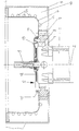
- the drawing figure shows one in longitudinal section and in a partial representation Laboratory centrifuge, especially its drive part.
- 1 is a Electric motor referred to, whose vertically oriented shaft 2 on her, from the the motor protruding free end is provided with a coupling part 3, which for connection to a centrifuge rotor, not shown in the drawing is determined and established.
- the motor housing especially its Upper part 4, including a bearing cover, is located within the bottom-side opening concentric to the shaft 2 5 of a boiler 6, which serves to hold the centrifuge rotor and the top can be closed by a cover, also not shown in the drawing is.
- the opening 5 of the boiler 6 is enclosed by an annular body 7, the said part 4 of the electric motor 1 radially at a distance while leaving of an annular gap 8 surrounds.
- the ring body 7 stands on the one hand with the boiler 6 and on the other hand with the boiler 6 on the outside at a distance, thus below Leaving a casing 10 surrounding the housing wall 9 in connection.
- the distance between the housing wall 9 and the boiler 6 can be mechanically stabilized by various internals.
- the system of lines 11 is not shown in the drawing Wisely integrated into a cycle that includes a heat sink includes the absorbed over the walls of the boiler 6 Dissipate heat.
- a control system which detects, for example, the temperature of the boiler walls and for Influencing the heat conducted through the lines 11 for the purpose of adjustment a defined internal temperature of the boiler 6 is determined and set up.
- part 4 On the end face 12 of part 4, covering this on the boiler room side is one cuff made of a rubber-elastic material, for example 13 attached, which in particular covers the annular gap 8 and the outer Boundary by means of a molded bead 14 in a concentric manner the shaft 2 extending annular groove 15 of the ring body 7 is fixed.
- the substances to be treated using such a laboratory centrifuge are located in not shown in the drawing, in the centrifuge rotor mentioned at the beginning usable vessels. Often this treatment takes place depending on the Properties of these substances under compared to the ambient temperatures reduced temperatures instead and it is for this purpose by means of a the lines 11 cooling medium flowing first a product-specific Temperature set inside the boiler, whereupon the centrifugative Treatment begins.
- the standstill heating of the electric motor 1 according to the invention takes place in accordance with a fixed heating output, which, taking into account the most unfavorable conditions, i.e. a maximum cooling output of the cooling medium flowing via the lines 11, results in a drop below the dew point of the parts of the motor which are thermally influenced by the boiler space avoids.
- the standstill heating can, however, be carried out variably as a function of the actual thermal influence, by means of one or more sensors which detect the temperature at the critical point (s) of the thermally influenced motor parts, the heating power to be used depending on the cooling determined in this way is measured.
- a particular advantage of the invention can be seen in the fact that no additional heating elements are to be provided within the motor in order to provide such anti-condensation heating and rather use is made of already existing structural elements, namely the winding elements of the rotor and / or the stator.
- Every laboratory centrifuge in the sense of the invention can be equipped in a simple manner and at low cost, which has the advantage that condensate-related corrosion damage within the motor is avoided, which is otherwise noticeable in the area of electrical contacts, but also in the case of bearing elements, and entails significant consequential costs would.
Landscapes
- Engineering & Computer Science (AREA)
- Power Engineering (AREA)
- Manufacturing & Machinery (AREA)
- Centrifugal Separators (AREA)
Description
Ein besonderer Vorteil der Erfindung ist darin zu sehen, daß zur Bereitstellung einer solchen Stillstandsheizung keine zusätzlichen Heizelemente innerhalb des Motors vorzusehen sind und vielmehr von bereits vorhandenen Strukturelementen Gebrauch gemacht wird, nämlich den Wicklungselementen des Rotors und/oder des Stators. Es ist jede Laborzentrifuge im erfindungsgemäßen Sinne in einfacher Weise und mit geringen Kosten ausrüstbar, denen der Vorteil gegenübersteht, daß kondensatbedingte Korrosionsschäden innerhalb des Motors vermieden werden, die sich ansonsten im Bereich elektrischer Kontakte, jedoch auch bei Lagerelementen bemerkbar machen und bedeutende Folgekosten nach sich ziehen würden.
Claims (5)
- Laborzentrifuge mit einem, zumindest einen Elektromotor (1) umfassenden Antrieb, der mit einem Zentrifugenrotor in Verbindung steht, der seinerseits mit mehreren auswechselbar angeordneten, zur Aufnahme von durch Zentrifugation zu behandelnden Stoffen bestimmten Gefäßen ausgerüstet ist, wobei der Zentrifugenrotor in einem temperierbaren, unterseitig mit einer, zur Durchführung von Teilen des Antriebes bestimmten Öffnung (5) versehenen Kessel (6) aufgenommen ist,
dadurch gekennzeichnet,daß der Elektromotor (1) mit einer Stillstandheizung versehen ist, deren Heizleistung dahingehend bemessen ist, daß nach Maßgabe einer stoffspezifischen Kühltemperatur innerhalb des Kessels (6) an keiner Stelle innerhalb des Motors eine Taupunktunterschreitung stattfindet unddaß die Stillstandheizung über eine Steuerung automatisch aktivierbar ist, und zwar in Abhängigkeit von der Abkühlung des Innenraumes des Kessels (6). - Laborzentrifuge nach Anspruch 1,
dadurch gekennzeichnet,daß die Stillstandheizung im Falle einer Kühlung des Innenraumes des Kessels (6) nach Maßgabe einer konstanten Heizleistung aktivierbar ist. - Laborzentrifuge nach Anspruch 1,
dadurch gekennzeichnet,daß die Stillstandheizung im Falle einer Kühlung des Innenraumes des Kessels (6) nach Maßgabe einer an die Innentemperatur des Kessels (6) angepaßten Heizleistung aktivierbar ist. - Laborzentrifuge nach Anspruch 1 oder 3,
gekennzeichnet durcheinen Temperaturfühler zur Erfassung eines Temperaturmeßwertes des Kessels (6), der in einen Regelkreis zum Regeln der Heizleistung der Stillstandheizung eingebunden ist. - Laborzentrifuge nach einem der Ansprüche 1 bis 4,
dadurch gekennzeichnet,daß die Stillstandheizung durch das Wicklungssystem des Stators und/oder des Rotors des Elektromotors gebildet ist unddaß die Stillstandheizung mit einer Regelungseinrichtung in Wirkverbindung steht, durch welche sie unter vorgebbaren Bedingungen und nach Maßgabe einer vorgebbaren Heizleistung aktiyierbar ist.
Applications Claiming Priority (3)
| Application Number | Priority Date | Filing Date | Title |
|---|---|---|---|
| DE29721563U DE29721563U1 (de) | 1997-12-05 | 1997-12-05 | Laborzentrifuge |
| DE29721563U | 1997-12-05 | ||
| PCT/EP1998/005831 WO1999029431A1 (de) | 1997-12-05 | 1998-09-14 | Laborzentrifuge mit elektromotor mit stillstandheizung |
Publications (2)
| Publication Number | Publication Date |
|---|---|
| EP1035924A1 EP1035924A1 (de) | 2000-09-20 |
| EP1035924B1 true EP1035924B1 (de) | 2002-05-02 |
Family
ID=8049568
Family Applications (1)
| Application Number | Title | Priority Date | Filing Date |
|---|---|---|---|
| EP98954277A Expired - Lifetime EP1035924B1 (de) | 1997-12-05 | 1998-09-14 | Laborzentrifuge mit elektromotor mit stillstandheizung |
Country Status (4)
| Country | Link |
|---|---|
| US (1) | US6342771B1 (de) |
| EP (1) | EP1035924B1 (de) |
| DE (2) | DE29721563U1 (de) |
| WO (1) | WO1999029431A1 (de) |
Families Citing this family (7)
| Publication number | Priority date | Publication date | Assignee | Title |
|---|---|---|---|---|
| WO2004045771A1 (en) * | 2002-11-19 | 2004-06-03 | Alphahelix Ab | Method and device for rapid homogenisation and mass transport |
| US8134328B2 (en) * | 2008-04-23 | 2012-03-13 | Honeywell International Inc. | Active pilot inceptor with self warm-up |
| DE102011105878A1 (de) * | 2011-06-14 | 2012-12-20 | Eppendorf Ag | Zentrifuge mit Kompressorkühlung |
| US9595854B2 (en) | 2014-08-12 | 2017-03-14 | Regal Beloit America, Inc. | Electric machine, moisture guide and associated method |
| CN106390906A (zh) * | 2016-12-05 | 2017-02-15 | 南京东擎科技有限公司 | 气相逆流的离心反应釜 |
| CN110586347B (zh) * | 2019-09-23 | 2024-03-29 | 南京中船绿洲机器有限公司 | 一种直驱式离心机驱动部件的装配方法 |
| US20220407398A1 (en) * | 2021-06-16 | 2022-12-22 | Lcdrives Corp. | Rotary electric machine with programmable interface |
Family Cites Families (11)
| Publication number | Priority date | Publication date | Assignee | Title |
|---|---|---|---|---|
| US3600900A (en) * | 1969-11-03 | 1971-08-24 | North American Rockwell | Temperature controlled centrifuge |
| DE2450482C1 (de) * | 1974-10-24 | 1985-10-31 | Messerschmitt-Bölkow-Blohm GmbH, 8000 München | Beheizbare Zentrifuge |
| JPS5453772U (de) * | 1977-09-24 | 1979-04-13 | ||
| US4195324A (en) | 1978-07-26 | 1980-03-25 | Allen-Bradley Company | Heating circuit for an electric motor |
| DE3343516C2 (de) * | 1983-12-01 | 1985-10-31 | Berthold Hermle Kg, 7209 Gosheim | Kühlzentrifuge mit auswechselbaren Rotoren |
| DD266745A1 (de) * | 1986-01-29 | 1989-04-12 | Medizin Labortechnik Veb K | Verfahren zur temperierung der rotoren von ultrazentrifugen |
| DE3720085A1 (de) | 1987-06-16 | 1988-12-29 | Berthold Hermle Gmbh & Co Masc | Verfahren und anordnung zur temperaturregelung insbesondere bei kuehlzentrifugen |
| US4913696A (en) | 1987-12-21 | 1990-04-03 | E. I. Du Pont De Nemours And Company | Support arrangement for a temperature sensor |
| DE4105733A1 (de) | 1991-02-23 | 1992-08-27 | Klein Schanzlin & Becker Ag | Motorstillstandsheizung |
| US5631509A (en) | 1994-07-27 | 1997-05-20 | General Electric Company | Motor having thermostatically controlled or limited space heater |
| DE19615702C1 (de) * | 1996-04-22 | 1997-10-02 | Heraeus Instr Gmbh | Labor-Zentrifuge |
-
1997
- 1997-12-05 DE DE29721563U patent/DE29721563U1/de not_active Expired - Lifetime
-
1998
- 1998-09-14 DE DE59804007T patent/DE59804007D1/de not_active Expired - Lifetime
- 1998-09-14 WO PCT/EP1998/005831 patent/WO1999029431A1/de not_active Ceased
- 1998-09-14 EP EP98954277A patent/EP1035924B1/de not_active Expired - Lifetime
- 1998-09-14 US US09/554,987 patent/US6342771B1/en not_active Expired - Lifetime
Also Published As
| Publication number | Publication date |
|---|---|
| DE29721563U1 (de) | 1999-01-14 |
| EP1035924A1 (de) | 2000-09-20 |
| WO1999029431A1 (de) | 1999-06-17 |
| US6342771B1 (en) | 2002-01-29 |
| DE59804007D1 (de) | 2002-06-06 |
Similar Documents
| Publication | Publication Date | Title |
|---|---|---|
| DE19843990C1 (de) | Integriertes Galettenaggregat | |
| DE69914484T2 (de) | Lüfter für Kühlschrank | |
| DE4038663C2 (de) | Wechselstrom-Lichtmaschine für Fahrzeuge | |
| DE3902592C2 (de) | Antrieb für die Werkstückspindel einer Werkzeugmaschine | |
| DE68907818T2 (de) | Belueftete elektromotoreinheit. | |
| DE19635044A1 (de) | Kühlmitteltemperatur-Regelsystem für Fahrzeuge | |
| DE112012003598T5 (de) | System und Verfahren zur Kühlung eines elektrischen Maschinenmoduls | |
| DE3905278A1 (de) | Durch einen elektronisch kommutierten motor angetriebene einrichtung | |
| EP2457308B1 (de) | Lüfter mit einem elektronisch kommutierten antriebsmotor | |
| DE2603557A1 (de) | Kleidungstrockner | |
| DE102013208226A1 (de) | Kühlelement für einen Radnabenantrieb sowie Radnabenantrieb | |
| DE102011081183A1 (de) | Ventil zur Steuerung von Volumenströmen | |
| DE29721563U1 (de) | Laborzentrifuge | |
| DE1498579A1 (de) | Anordnung zur Steuerung der Temperatur eines Zentrifugen-Rotors | |
| DE3324076C2 (de) | ||
| DE3231611T1 (de) | Temperature regulation system for electric vehicules | |
| EP0424867A1 (de) | Kühlvorrichtung für Elektromotoren | |
| DE4113198A1 (de) | Elektromotor, insbesondere spaltrohrmotor fuer eine kreiselpumpe oder einen luefter | |
| EP3610563A1 (de) | Verfahren zum kühlen einer getriebelosen windenergieanlage | |
| DE112014003821T5 (de) | Motorgetriebener Kompressor | |
| EP0582217B1 (de) | Kühlflüssigkeitsgekühltes Stromrichtermodul mit einer durch eine Kühlmittelpumpe erzeugten Kühlflüssigkeitsströmung | |
| DE102015217917A1 (de) | Steuervorrichtung mit integrierter rotierender elektrischer Maschine | |
| DE3305301A1 (de) | Antriebsvorrichtung | |
| EP3794718B1 (de) | Ec-motor mit einer welle, einer kommutierungselektronik und einer vorrichtung zum detektieren eines temperaturanstiegs | |
| DE68927549T2 (de) | Träger für temperaturfühler |
Legal Events
| Date | Code | Title | Description |
|---|---|---|---|
| PUAI | Public reference made under article 153(3) epc to a published international application that has entered the european phase |
Free format text: ORIGINAL CODE: 0009012 |
|
| 17P | Request for examination filed |
Effective date: 19991106 |
|
| AK | Designated contracting states |
Kind code of ref document: A1 Designated state(s): DE FR GB |
|
| GRAG | Despatch of communication of intention to grant |
Free format text: ORIGINAL CODE: EPIDOS AGRA |
|
| 17Q | First examination report despatched |
Effective date: 20010612 |
|
| GRAG | Despatch of communication of intention to grant |
Free format text: ORIGINAL CODE: EPIDOS AGRA |
|
| GRAH | Despatch of communication of intention to grant a patent |
Free format text: ORIGINAL CODE: EPIDOS IGRA |
|
| GRAH | Despatch of communication of intention to grant a patent |
Free format text: ORIGINAL CODE: EPIDOS IGRA |
|
| REG | Reference to a national code |
Ref country code: GB Ref legal event code: IF02 |
|
| GRAA | (expected) grant |
Free format text: ORIGINAL CODE: 0009210 |
|
| AK | Designated contracting states |
Kind code of ref document: B1 Designated state(s): DE FR GB |
|
| REG | Reference to a national code |
Ref country code: GB Ref legal event code: FG4D Free format text: NOT ENGLISH |
|
| GBT | Gb: translation of ep patent filed (gb section 77(6)(a)/1977) |
Effective date: 20020502 |
|
| REF | Corresponds to: |
Ref document number: 59804007 Country of ref document: DE Date of ref document: 20020606 |
|
| ET | Fr: translation filed | ||
| PLBE | No opposition filed within time limit |
Free format text: ORIGINAL CODE: 0009261 |
|
| STAA | Information on the status of an ep patent application or granted ep patent |
Free format text: STATUS: NO OPPOSITION FILED WITHIN TIME LIMIT |
|
| 26N | No opposition filed |
Effective date: 20030204 |
|
| REG | Reference to a national code |
Ref country code: DE Ref legal event code: R082 Representative=s name: REHBERG HUEPPE + PARTNER PATENTANWAELTE PARTG , DE Ref document number: 59804007 Country of ref document: DE |
|
| REG | Reference to a national code |
Ref country code: DE Ref legal event code: R082 Ref document number: 59804007 Country of ref document: DE Representative=s name: REHBERG HUEPPE + PARTNER PATENTANWAELTE PARTG , DE Ref country code: DE Ref legal event code: R082 Ref document number: 59804007 Country of ref document: DE |
|
| REG | Reference to a national code |
Ref country code: FR Ref legal event code: PLFP Year of fee payment: 19 |
|
| REG | Reference to a national code |
Ref country code: FR Ref legal event code: PLFP Year of fee payment: 20 |
|
| PGFP | Annual fee paid to national office [announced via postgrant information from national office to epo] |
Ref country code: FR Payment date: 20170925 Year of fee payment: 20 Ref country code: DE Payment date: 20170704 Year of fee payment: 20 Ref country code: GB Payment date: 20170925 Year of fee payment: 20 |
|
| REG | Reference to a national code |
Ref country code: DE Ref legal event code: R071 Ref document number: 59804007 Country of ref document: DE |
|
| REG | Reference to a national code |
Ref country code: GB Ref legal event code: PE20 Expiry date: 20180913 |
|
| PG25 | Lapsed in a contracting state [announced via postgrant information from national office to epo] |
Ref country code: GB Free format text: LAPSE BECAUSE OF EXPIRATION OF PROTECTION Effective date: 20180913 |