EP1035378A2 - Appareil ménager de cuisson à gaz muni d' un dispositif simplifié d'allumage à étincelles - Google Patents
Appareil ménager de cuisson à gaz muni d' un dispositif simplifié d'allumage à étincelles Download PDFInfo
- Publication number
- EP1035378A2 EP1035378A2 EP00103200A EP00103200A EP1035378A2 EP 1035378 A2 EP1035378 A2 EP 1035378A2 EP 00103200 A EP00103200 A EP 00103200A EP 00103200 A EP00103200 A EP 00103200A EP 1035378 A2 EP1035378 A2 EP 1035378A2
- Authority
- EP
- European Patent Office
- Prior art keywords
- cock
- cocks
- microswitch
- cooking equipment
- striking element
- Prior art date
- Legal status (The legal status is an assumption and is not a legal conclusion. Google has not performed a legal analysis and makes no representation as to the accuracy of the status listed.)
- Granted
Links
Images
Classifications
-
- F—MECHANICAL ENGINEERING; LIGHTING; HEATING; WEAPONS; BLASTING
- F24—HEATING; RANGES; VENTILATING
- F24C—DOMESTIC STOVES OR RANGES ; DETAILS OF DOMESTIC STOVES OR RANGES, OF GENERAL APPLICATION
- F24C3/00—Stoves or ranges for gaseous fuels
- F24C3/10—Arrangement or mounting of ignition devices
- F24C3/103—Arrangement or mounting of ignition devices of electric ignition devices
Definitions
- the invention relates to a device capable of reducing the number of microswitches usually used for the spark ignition of the gas burners of household cooking equipment.
- this circuit there may be a special ignition button which comes into contact with the microswitches in series with the ignition plugs: this is located on the panel of the cooking equipment, independently of the knobs for the cocks, and the ignition is achieved by this being pushed down while the burner cock is opened at the same time.
- cocks equipped with a microswitch are connected in parallel in the single electrical circuit which supplies all the igniter plugs.
- the knob of the cock for the burner needed to be ignited is pressed, the relative solenoid valve to the burner opens while the microswitch, necessarily closes and, as in the case of a single button separate from the cocks, produces a spark from all the igniter plugs.
- the microswitch is a separate element which can be mounted on the cock adapted to receive it.
- the present invention in the case of household cooking equipment fitted with at least two gas burners supplied by means of corresponding cocks mounted next to each other and fitted with a spark ignition activated by means of microswitches attached to the said cocks, aims to allow the removal of one microswitch from each pair of adjacent cocks.
- a further aim of the present invention is to achieve this objective by simply applying an additional mechanical element to the standard cocks manufactured according to the commonly-known technique.
- aims are achieved through a device according to the present invention in which the ignition spark is produced, for at least one cock because the said cock is equipped with a striking element which comes into contact with the microswitch mounted either on a second cock or close to this latter or positioned between the two and, however, in such a way that the said microswitch can be activated by both the first and the second cock, each one independently of the other.
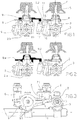
- Figure 1 shows a frontal view, according to an embodiment of the present invention, of two adjacent cocks, both manufactured according to the commonly-known technique with the only difference that, on the first cock there is a spark ignition microswitch manufactured, mounted and activated according to the commonly-known technique, while the second cock does not have a microswitch but an additional mechanical element which can activate the microswitch of the first cock.
- Figure 2 shows a further frontal view, substantially the same elements of the previous figure with only one variation relating to the additional mechanical element according to the present invention.
- Figure 3 shows a top view of the same elements of figure 1 as well as the so-called 'ramp', i.e. the tubing which supplies the gas cocks: the ramp is omitted in the previous figures for the sake of clarity.
- n o 1 denotes the gas ramp
- n o 2 denotes the body of a standard gas cock designed according to the commonly-known technique
- n o 2.b denotes a standard gas cock which can even be identical to the cock 2 except that it is fitted with an additional element according to the invention
- n o 3 denotes the cylindrical flange by means of which either gas cock 2 or 2 .b can be coupled to the ramp 1
- n o 4 denotes any of the knobs for gas cocks 2 or 2.b
- n o 5 denotes the shaft of a knob 4
- n o 6 denotes the body of a solenoid valve
- n o 6.1 denotes the feeler pin of the solenoid valve 6 whose pressure enables the opening of the solenoid valve 6 itself
- n o 7 denotes a microswitch mounted on a cock 2
- n o 7.1 denotes the feel
- the microswitch 7 is non incorporated in the cock 2 but simply mounted on this latter. If the knob 4 is pressed, the shaft 5 moves downwards and the striking element 8, mounted on to the shaft 5, crushes both the feeler pin 6.1 of the solenoid valve, opening it, and also the feeler pin 7.1 of the microswitch 7, if present.
- the said striking element 9 makes it possible not to mount a microswitch 7 on either of the cocks 2.b adjacent to a cock 2.
- the striking element 9 can be manufactured using any commonly-known material and technology and so it is not necessary to describe them.
- a preferred embodiment envisages moulded plastic, of a suitable mechanical and thermal resistance, fitted with hooking teeth 9.1 with which the striking element 8 can be locked in place.
- the said striking element 9 has a seating for coupling with the striking element 8 formed in such a way as to ensure the correct positioning of the first element with the second element, as the non-symmetrical positions of the teeth 9.1 show in the example in Fig. 3.
- a striking element 9.a is envisaged comprising the striking element 8 with the end 9.2 added.
- the material used will be the same as the material currently used to manufacture the striking elements 8. It could be advantageous, for production simplicity, to fit all the cocks 2 and 2.b., whether they are fitted with the microswitch 7 or not, with the same striking element 9 whose end 9.2, at the most, will not be used.
- the present invention has been described applied to gas cocks designed to be installed in cooking equipment fitted with a horizontal panel, but it is clear that, with elements and mechanical means equivalent to those described, this could also be applied to many other household gas cooking equipment in which optional ignition microswitches are mounted on the cocks and they are accessible, for activation, from the outside of the body of the said cocks.
- the said microswitch 7 mounted on a cock 2 cannot be accessed easily, because of its shape or position, by the striking elements 9 or 9.a mounted on a cock 2 .b, then the said microswitch 7 can be positioned between the two cocks 2.b, each one fitted with a striking element 9 or 9.a with the ends 9.2. in the appropriate positions, which can be identical if necessary.
Landscapes
- Engineering & Computer Science (AREA)
- Chemical & Material Sciences (AREA)
- Combustion & Propulsion (AREA)
- Mechanical Engineering (AREA)
- General Engineering & Computer Science (AREA)
- Feeding And Controlling Fuel (AREA)
- Push-Button Switches (AREA)
- Mounting, Exchange, And Manufacturing Of Dies (AREA)
Applications Claiming Priority (2)
| Application Number | Priority Date | Filing Date | Title |
|---|---|---|---|
| IT99AN000011 IT248927Y1 (it) | 1999-03-08 | 1999-03-08 | Apparecchi di cottura domestici a gas con dispositivo di accensionea scintilla semplificato |
| ITAN990011U | 1999-03-08 |
Publications (3)
| Publication Number | Publication Date |
|---|---|
| EP1035378A2 true EP1035378A2 (fr) | 2000-09-13 |
| EP1035378A3 EP1035378A3 (fr) | 2001-04-25 |
| EP1035378B1 EP1035378B1 (fr) | 2006-06-28 |
Family
ID=11334295
Family Applications (1)
| Application Number | Title | Priority Date | Filing Date |
|---|---|---|---|
| EP20000103200 Expired - Lifetime EP1035378B1 (fr) | 1999-03-08 | 2000-02-17 | Appareil ménager de cuisson à gaz muni d' un dispositif simplifié d'allumage à étincelles |
Country Status (4)
| Country | Link |
|---|---|
| EP (1) | EP1035378B1 (fr) |
| DE (1) | DE60029037T2 (fr) |
| ES (1) | ES2267423T3 (fr) |
| IT (1) | IT248927Y1 (fr) |
Cited By (2)
| Publication number | Priority date | Publication date | Assignee | Title |
|---|---|---|---|---|
| EP1500881A2 (fr) * | 2003-07-25 | 2005-01-26 | ITW Industrial Components S.r.l. | Dispositif intégré pour plaque de cuisson comprenant un robinet de gaz et un dispositif d'allumage |
| EP2390575A3 (fr) * | 2010-05-24 | 2013-01-09 | BSH Bosch und Siemens Hausgeräte GmbH | Vanne de gaz dotée d'un élément d'actionnement pour un commutateur électrique |
Family Cites Families (3)
| Publication number | Priority date | Publication date | Assignee | Title |
|---|---|---|---|---|
| DE1429108C3 (de) * | 1963-02-06 | 1978-04-06 | Imperial-Werke Gmbh, 4980 Buende | Hochspannungszündeinrichtung für Gasbrennstellen an Gasherden u.dgl |
| DE1905797A1 (de) * | 1969-02-06 | 1970-10-01 | Junkers & Co | Gasherd mit mehreren Brennern und mit einer piezoelektrischen Zuendvorrichtung |
| FR2708087B1 (fr) * | 1993-07-23 | 1995-09-01 | Cepem | Dispositif d'allumage intégré pour appareil à gaz. |
-
1999
- 1999-03-08 IT IT99AN000011 patent/IT248927Y1/it active
-
2000
- 2000-02-17 ES ES00103200T patent/ES2267423T3/es not_active Expired - Lifetime
- 2000-02-17 EP EP20000103200 patent/EP1035378B1/fr not_active Expired - Lifetime
- 2000-02-17 DE DE2000629037 patent/DE60029037T2/de not_active Expired - Fee Related
Non-Patent Citations (1)
| Title |
|---|
| None |
Cited By (4)
| Publication number | Priority date | Publication date | Assignee | Title |
|---|---|---|---|---|
| EP1500881A2 (fr) * | 2003-07-25 | 2005-01-26 | ITW Industrial Components S.r.l. | Dispositif intégré pour plaque de cuisson comprenant un robinet de gaz et un dispositif d'allumage |
| EP1500881A3 (fr) * | 2003-07-25 | 2005-06-15 | ITW Industrial Components S.r.l. | Dispositif intégré pour plaque de cuisson comprenant un robinet de gaz et un dispositif d'allumage |
| US7243647B2 (en) | 2003-07-25 | 2007-07-17 | Itw Industrial Components S.R.L. | Universal integrated device for controlling gas-burner rings of a cooking surface including a gas tap and a catenary element |
| EP2390575A3 (fr) * | 2010-05-24 | 2013-01-09 | BSH Bosch und Siemens Hausgeräte GmbH | Vanne de gaz dotée d'un élément d'actionnement pour un commutateur électrique |
Also Published As
| Publication number | Publication date |
|---|---|
| EP1035378B1 (fr) | 2006-06-28 |
| IT248927Y1 (it) | 2003-03-06 |
| DE60029037T2 (de) | 2007-01-11 |
| ES2267423T3 (es) | 2007-03-16 |
| ITAN990011U1 (it) | 1999-06-08 |
| EP1035378A3 (fr) | 2001-04-25 |
| DE60029037D1 (de) | 2006-08-10 |
Similar Documents
| Publication | Publication Date | Title |
|---|---|---|
| US9706872B2 (en) | Control device for gas taps | |
| US5525771A (en) | Spark ignition switch and valve assembly for gas burners including external detent assembly | |
| US8381716B2 (en) | Flame ignition device for gas burners | |
| US6375150B1 (en) | Knob for gas apparatus with safety button | |
| US6541721B1 (en) | Electrical switch for gas cocks | |
| EP3175176B1 (fr) | Dispositif de commande d'allumage de flamme pour brûleurs ou similaire | |
| EP1035378A2 (fr) | Appareil ménager de cuisson à gaz muni d' un dispositif simplifié d'allumage à étincelles | |
| EP1207348A1 (fr) | Briquet à interrupteur de verrouillage | |
| CA2354608C (fr) | Briquet electronique de securite | |
| US11353216B2 (en) | Switch assembly | |
| EP1856451A1 (fr) | Appareil a gaz, en particulier plaque de cuisson a gaz | |
| WO2007013014A2 (fr) | Appareil de cuisson | |
| DE4238816C1 (de) | Gasherd mit einer Herdplatte aus Glaskeramik | |
| EP3077730A1 (fr) | Dispositif de cuisson à gaz | |
| GB1488137A (en) | Piezoelectric lighters for domestic appliances burners | |
| JPS6040568B2 (ja) | ガス燃焼安全装置 | |
| KR910000557Y1 (ko) | 가스압력솥의 가스밸브 | |
| KR880000400Y1 (ko) | 가스 곤로 장치 | |
| JPH087238Y2 (ja) | ボンベ内蔵型ガスこんろの緊急遮断弁のリセット装置 | |
| KR200257762Y1 (ko) | 압력 밥솥의 증기 배출 밸브 | |
| KR920005748Y1 (ko) | 가스레인지의 점화장치 | |
| KR900008319Y1 (ko) | 가스 기기의 점화 장치 | |
| JPS5932823Y2 (ja) | ガス燃焼器の安全装置 | |
| KR890002953Y1 (ko) | 가스 점화장치의 마이크로스위치 | |
| KR0143693B1 (ko) | 가스오븐렌지의 도어 잠금장치 |
Legal Events
| Date | Code | Title | Description |
|---|---|---|---|
| PUAI | Public reference made under article 153(3) epc to a published international application that has entered the european phase |
Free format text: ORIGINAL CODE: 0009012 |
|
| AK | Designated contracting states |
Kind code of ref document: A2 Designated state(s): DE ES FR GB |
|
| AX | Request for extension of the european patent |
Free format text: AL;LT;LV;MK;RO;SI |
|
| PUAL | Search report despatched |
Free format text: ORIGINAL CODE: 0009013 |
|
| AK | Designated contracting states |
Kind code of ref document: A3 Designated state(s): AT BE CH CY DE DK ES FI FR GB GR IE IT LI LU MC NL PT SE |
|
| AX | Request for extension of the european patent |
Free format text: AL;LT;LV;MK;RO;SI |
|
| 17P | Request for examination filed |
Effective date: 20010305 |
|
| AKX | Designation fees paid |
Free format text: DE ES FR GB |
|
| 17Q | First examination report despatched |
Effective date: 20040414 |
|
| RAP1 | Party data changed (applicant data changed or rights of an application transferred) |
Owner name: INDESIT COMPANY S.P.A. |
|
| GRAP | Despatch of communication of intention to grant a patent |
Free format text: ORIGINAL CODE: EPIDOSNIGR1 |
|
| GRAS | Grant fee paid |
Free format text: ORIGINAL CODE: EPIDOSNIGR3 |
|
| GRAA | (expected) grant |
Free format text: ORIGINAL CODE: 0009210 |
|
| AK | Designated contracting states |
Kind code of ref document: B1 Designated state(s): DE ES FR GB |
|
| REG | Reference to a national code |
Ref country code: GB Ref legal event code: FG4D |
|
| REF | Corresponds to: |
Ref document number: 60029037 Country of ref document: DE Date of ref document: 20060810 Kind code of ref document: P |
|
| ET | Fr: translation filed | ||
| REG | Reference to a national code |
Ref country code: ES Ref legal event code: FG2A Ref document number: 2267423 Country of ref document: ES Kind code of ref document: T3 |
|
| PLBE | No opposition filed within time limit |
Free format text: ORIGINAL CODE: 0009261 |
|
| STAA | Information on the status of an ep patent application or granted ep patent |
Free format text: STATUS: NO OPPOSITION FILED WITHIN TIME LIMIT |
|
| 26N | No opposition filed |
Effective date: 20070329 |
|
| PGFP | Annual fee paid to national office [announced via postgrant information from national office to epo] |
Ref country code: DE Payment date: 20090331 Year of fee payment: 10 |
|
| PG25 | Lapsed in a contracting state [announced via postgrant information from national office to epo] |
Ref country code: DE Free format text: LAPSE BECAUSE OF NON-PAYMENT OF DUE FEES Effective date: 20100901 |
|
| PGFP | Annual fee paid to national office [announced via postgrant information from national office to epo] |
Ref country code: ES Payment date: 20110223 Year of fee payment: 12 Ref country code: GB Payment date: 20110216 Year of fee payment: 12 |
|
| PGFP | Annual fee paid to national office [announced via postgrant information from national office to epo] |
Ref country code: FR Payment date: 20120316 Year of fee payment: 13 |
|
| GBPC | Gb: european patent ceased through non-payment of renewal fee |
Effective date: 20120217 |
|
| PG25 | Lapsed in a contracting state [announced via postgrant information from national office to epo] |
Ref country code: GB Free format text: LAPSE BECAUSE OF NON-PAYMENT OF DUE FEES Effective date: 20120217 |
|
| REG | Reference to a national code |
Ref country code: ES Ref legal event code: FD2A Effective date: 20130709 |
|
| PG25 | Lapsed in a contracting state [announced via postgrant information from national office to epo] |
Ref country code: ES Free format text: LAPSE BECAUSE OF NON-PAYMENT OF DUE FEES Effective date: 20120218 |
|
| REG | Reference to a national code |
Ref country code: FR Ref legal event code: ST Effective date: 20131031 |
|
| PG25 | Lapsed in a contracting state [announced via postgrant information from national office to epo] |
Ref country code: FR Free format text: LAPSE BECAUSE OF NON-PAYMENT OF DUE FEES Effective date: 20130228 |