EP1035264B1 - Als raumteiler und möbelträger verwendbare wand - Google Patents
Als raumteiler und möbelträger verwendbare wand Download PDFInfo
- Publication number
- EP1035264B1 EP1035264B1 EP98943904A EP98943904A EP1035264B1 EP 1035264 B1 EP1035264 B1 EP 1035264B1 EP 98943904 A EP98943904 A EP 98943904A EP 98943904 A EP98943904 A EP 98943904A EP 1035264 B1 EP1035264 B1 EP 1035264B1
- Authority
- EP
- European Patent Office
- Prior art keywords
- screen
- section
- partition
- furniture support
- grooves
- Prior art date
- Legal status (The legal status is an assumption and is not a legal conclusion. Google has not performed a legal analysis and makes no representation as to the accuracy of the status listed.)
- Expired - Lifetime
Links
- 238000005192 partition Methods 0.000 title claims description 14
- 230000003042 antagnostic effect Effects 0.000 claims 1
- 239000000470 constituent Substances 0.000 claims 1
- 238000004873 anchoring Methods 0.000 description 3
- 238000010276 construction Methods 0.000 description 2
- 238000003780 insertion Methods 0.000 description 2
- 230000037431 insertion Effects 0.000 description 2
- 239000005557 antagonist Substances 0.000 description 1
- 230000000295 complement effect Effects 0.000 description 1
- 230000008878 coupling Effects 0.000 description 1
- 238000010168 coupling process Methods 0.000 description 1
- 238000005859 coupling reaction Methods 0.000 description 1
- 230000005611 electricity Effects 0.000 description 1
- 238000005286 illumination Methods 0.000 description 1
- 238000009434 installation Methods 0.000 description 1
- 239000012528 membrane Substances 0.000 description 1
- 230000002787 reinforcement Effects 0.000 description 1
Images


Classifications
-
- E—FIXED CONSTRUCTIONS
- E04—BUILDING
- E04B—GENERAL BUILDING CONSTRUCTIONS; WALLS, e.g. PARTITIONS; ROOFS; FLOORS; CEILINGS; INSULATION OR OTHER PROTECTION OF BUILDINGS
- E04B2/00—Walls, e.g. partitions, for buildings; Wall construction with regard to insulation; Connections specially adapted to walls
- E04B2/74—Removable non-load-bearing partitions; Partitions with a free upper edge
- E04B2/7407—Removable non-load-bearing partitions; Partitions with a free upper edge assembled using frames with infill panels or coverings only; made-up of panels and a support structure incorporating posts
- E04B2/7416—Removable non-load-bearing partitions; Partitions with a free upper edge assembled using frames with infill panels or coverings only; made-up of panels and a support structure incorporating posts with free upper edge, e.g. for use as office space dividers
- E04B2/7422—Removable non-load-bearing partitions; Partitions with a free upper edge assembled using frames with infill panels or coverings only; made-up of panels and a support structure incorporating posts with free upper edge, e.g. for use as office space dividers with separate framed panels without intermediary support posts
- E04B2/7425—Details of connection of panels
-
- E—FIXED CONSTRUCTIONS
- E04—BUILDING
- E04B—GENERAL BUILDING CONSTRUCTIONS; WALLS, e.g. PARTITIONS; ROOFS; FLOORS; CEILINGS; INSULATION OR OTHER PROTECTION OF BUILDINGS
- E04B1/00—Constructions in general; Structures which are not restricted either to walls, e.g. partitions, or floors or ceilings or roofs
- E04B1/38—Connections for building structures in general
- E04B1/61—Connections for building structures in general of slab-shaped building elements with each other
- E04B1/6108—Connections for building structures in general of slab-shaped building elements with each other the frontal surfaces of the slabs connected together
- E04B1/612—Connections for building structures in general of slab-shaped building elements with each other the frontal surfaces of the slabs connected together by means between frontal surfaces
- E04B1/6145—Connections for building structures in general of slab-shaped building elements with each other the frontal surfaces of the slabs connected together by means between frontal surfaces with recesses in both frontal surfaces co-operating with an additional connecting element
- E04B1/6158—Connections for building structures in general of slab-shaped building elements with each other the frontal surfaces of the slabs connected together by means between frontal surfaces with recesses in both frontal surfaces co-operating with an additional connecting element the connection made by formlocking
-
- E—FIXED CONSTRUCTIONS
- E04—BUILDING
- E04B—GENERAL BUILDING CONSTRUCTIONS; WALLS, e.g. PARTITIONS; ROOFS; FLOORS; CEILINGS; INSULATION OR OTHER PROTECTION OF BUILDINGS
- E04B2/00—Walls, e.g. partitions, for buildings; Wall construction with regard to insulation; Connections specially adapted to walls
- E04B2/74—Removable non-load-bearing partitions; Partitions with a free upper edge
- E04B2002/7461—Details of connection of sheet panels to frame or posts
- E04B2002/7462—Details of connection of sheet panels to frame or posts using resilient connectors, e.g. clips
-
- E—FIXED CONSTRUCTIONS
- E04—BUILDING
- E04B—GENERAL BUILDING CONSTRUCTIONS; WALLS, e.g. PARTITIONS; ROOFS; FLOORS; CEILINGS; INSULATION OR OTHER PROTECTION OF BUILDINGS
- E04B2/00—Walls, e.g. partitions, for buildings; Wall construction with regard to insulation; Connections specially adapted to walls
- E04B2/74—Removable non-load-bearing partitions; Partitions with a free upper edge
- E04B2002/7461—Details of connection of sheet panels to frame or posts
- E04B2002/7466—Details of connection of sheet panels to frame or posts using hooks
-
- E—FIXED CONSTRUCTIONS
- E04—BUILDING
- E04B—GENERAL BUILDING CONSTRUCTIONS; WALLS, e.g. PARTITIONS; ROOFS; FLOORS; CEILINGS; INSULATION OR OTHER PROTECTION OF BUILDINGS
- E04B2/00—Walls, e.g. partitions, for buildings; Wall construction with regard to insulation; Connections specially adapted to walls
- E04B2/74—Removable non-load-bearing partitions; Partitions with a free upper edge
- E04B2002/749—Partitions with screw-type jacks
Definitions
- the invention here disclosed relates to elements which comprise a screen for partitions and furniture support, from among those which are meant to partition a working space in a flexible and reconfigurable manner, characterised by special sections, a transverse universal connection means for the screens, an anchoring system for external elements at any height and an anchoring system for the walls by clips.
- Partitions are widely known and form a part of accessories for offices and more, so that they require no further explanation.
- the applicant is unaware of the existence of systems for connection, attachment and construction such as those described in this description.
- the objective of the present invention is to overcome the above mentioned drawbacks developing a screen for partitions which comprises the additional pieces and configuration to get the above mentioned advantages.
- the invention object of the present description relates to systems for attachment, connection and construction of a partition screen comprising specially designed metallic sections, plate brackets, universal connection elements, rhomboidal parts for supporting external elements and clips for attachment of walls.
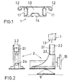
- Figure 1 shows the general section of the screens.
- Figure 2 shows the lower bracket of the screen as well as the section which forms the baseboard of the screen, and also the levelling element which is screwed on to the bracket and end piece (10).
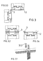
- Figure 3 shows the universal connection system for any angle and height.
- Figure 4 shows the part which when inserted in the side groove of figure 1 will be used to support working plans, shelves, hanging closets, illumination etc.
- Figure 5 shows an elevation and plan view of the top connection bracket between the upright pillars and the top crossbeam.
- Figure 6 shows a partially sectioned view of the screen, showing the walls employed as well as their assembly to the structure by clip type connectors.
- the partition screen and furniture support comprises three segments (two upright pillars and a top crossbeam) of a special section (1) which allows to obtain rectangular screens of width and height adjustable at will by the lengths cut of said pillars and crossbeams.
- a bottom bar (8) (figure 6) with a triple function: bottom structural element; baseboard and wiring conduct allowing installation without threading.
- the section of figure 1 is provided with lateral grooves (1.1) which allow to couple at any point and without breaking continuity screws with Allen mortises and rhomboidal ends (figure 4). It is also provided with a groove (1.4) on its lower face, of identical geometry as (1.1) which allows to couple at any point and without breaking continuity attachment part (7.1) (figure 6) antagonist of clips (7.2) (figure 6) which are screwed to the walls.
- the section of figure 1 is also provided with longitudinal grooves which allow to insert parts (3) (figure 3) known as universal connectors, meant to allow coupling to adjacent panels by pairs or in knots of three or four panels at different angles and heights. It is further provided with a lower groove (1.3) such that it allows to insert a top bracket (figure 5) meant to assemble both pillars and the top crossbar at 90°. The same groove (1.3) allow insertion of a lower bracket (figure 2).
- the lower bracket (figure 2) fulfils several functions required by the screen's function and assembly.
- the first a stiff connection to the bracket which allows a quick and self-centering assembly of the upright pillars (section 1) and which meet plateau (2.3) parallel to the base on said bracket and the lower structural cross beam.
- Stiffness is achieved by the expansion of two pyramidal trunks (2.2) which self-centre on the lower geometry of pillars (1.3) (section 1), by the action of a screw (2.4) which forces a wedge (2.1) to slide downwards, driven by the inner geometry (1.3) of section (1) and the inclined planes of arms (2.2) which expand and cause it to lock in place.
- the second function of the bracket of figure 2 is to hold an end clip (10) of the electricity baseboard when the screen is an end screen.
- the bracket is used to couple a levelling element (9),
- the sturdiness and design of its plate reinforcements allow to reduce the thickness of the element in order to allow the fourth function, which is the free passage of cables on either side of the bracket from each panel to adjacent ones without exceeding the total width of the screen and without reducing the structural strength required to support the classification and working drawings accessories incorporated as well as standard loads.
- Universal connection part (3) (figure 3) consists of a vertical connection membrane between two panels which ends in corresponding vertical cylinders provided with internal elastic hollow spaces, which allow by insertion of male elements (3.1.2) (figure 3) expansion of their walls and locking and attachment of each cylinder to grooves (1.2) of sections (1), corresponding to the pillars of two adjacent panels, whatever the height (figure 3.1) and angle in which they are to be connected, a 180° angle between panels in figure 3.2, a 90° angle between panels in figure 3.3 or a variable angle in figure 3.4. In this manner both panels are rigidly connected in position.
- the top bracket (figure 5) allows connection and self centering of the upright bars to the top pillar by two perpendicular arms in a U shape (5.2) which are tightly fitted in the inside (1.3) of section (1).
- Vertical groove (5.1), continuous with groove (1.2) of section (1) allows to connect adjacent panels without requiring disassembly of the walls by inserting the parts described in figure 1 along the entire length of section (1). Similarly, any screen may be removed from the set by extracting these parts (figure 3) without moving the adjacent screens nor disassembling any walls.
- the means of attaching the walls to the screen is through parts (7.1) coupled to groove (1.4) of the section, allowing a double anchoring of the walls by attachment clips (7.2) (figure 6). This allows a simple assembly, disassembly, replacement and exchange of the walls and access to the inside of the screen.
Landscapes
- Engineering & Computer Science (AREA)
- Architecture (AREA)
- Physics & Mathematics (AREA)
- Electromagnetism (AREA)
- Civil Engineering (AREA)
- Structural Engineering (AREA)
- Furniture Connections (AREA)
- Assembled Shelves (AREA)
- Connection Of Plates (AREA)
- Clamps And Clips (AREA)
Claims (5)
- Unterteilungsschirm und Möbelauflagerung, der über Folgendes verfügt:metallische Abschnitte (1), die eine Struktur bilden, auf der andere Bestandteile des Schirms befestigt werden,untere Träger (2), die auf den unteren Ecken des Schirms angebracht werdenein universelles Befestigungssystem (3), um den Schirm mit ähnlichen Schirmen zu verbindenobere Träger (5), die auf den oberen Ecken des Schirms angebracht werdenKlammern (7.1, 7.2) zur Befestigung an der Wand; dadurch gekennzeichnet, dass der Schirm desweiteren romboide Teile mit Sechskantnuten (6) umfasst, um externe Elemente aufzunehmen, die metallischen Abschnitte über zwei erste Vertiefungen (1.1) verfügen, um die romboiden Teile mit den Sechskantnuten (6) zu befestigen, durch die die externen Elemente gehalten werden können, eine zweite Vertiefung (1.4), um die Klammern (7.1) der antagonistischen Halterung (7.2) einzuführen, die es erlauben, die Wände an den Strukturen zu befestigen und weitere Vertiefungen (1.2), die mit dem universellen Befestigungssystem (3) nebeneinanderliegende ähnliche Schirme verbinden und dadurch, dass die unteren Träger (2) auf ihrer unteren Oberfläche mit den Abschnitten des Grundbretts (8) verbunden sind und dadurch, dass sie einen Ausdehnungskeil (2.1) umfassen, der zwischen Klappen (2.2) gleitet, die selbstzentrierend sind und innerhalb des inneren Hohlraums (1.3) der speziellen metallischen Abschnitte (1) einrasten, womit der Abschnitt (8) des Grundbretts an den speziellen metallischen Abschnitten (1) befestigt wird, die die senkrechten Stützen des Schirms umfassen.
- Unterteilungsschirm und Möbelauflagerung gemäss Anspruch 1, dadurch gekennzeichnet, dass das universelle Verbindungssystem (3) in die weiteren Vertiefungen (1.2) der speziellen metallischen Abschnitte (1) eingeführt wird, womit die Verbindung an verschiedenen Höhen und in verschiedenen Winkeln von zwei, drei oder vier nebeneinanderliegenden Schirmen ermöglicht wird.
- Unterteilungsschirm und Möbelauflagerung gemäss einem der vorangegangenen Ansprüche, dadurch gekennzeichnet, dass die romboiden Teile mit Sechskantnuten (6) in die ersten Vertiefungen (1.1) eingeführt wird, was ermöglicht, dass es Möbel trägt wie Werkszeichnungen oder Regalbretter.
- Unterteilungsschirm und Möbelauflagerung gemäss einem der vorangegangenen Ansprüche, dadurch gekennzeichnet, dass der obere Träger (5) vertikale Stangen mit einer oberen Stange verbindet und das universelle Verbindungssystem (3) auf seiner gesamten Länge zu den weiteren Vertiefungen (1.2) des speziellen metallischen Abschnitts (1) gelangen lässt.
- Unterteilungsschirm und Möbelauflagerung gemäss einem der vorangegangenen Ansprüche, dadurch gekennzeichnet, dass die Klammern zur Befestigung an der Wand (7.1) und (7.2) den einfachen Aufbau, Abbau, Austausch und Ersatz der Wände und den Zugang zum Inneren des Schirms erlauben.
Applications Claiming Priority (1)
| Application Number | Priority Date | Filing Date | Title |
|---|---|---|---|
| PCT/ES1998/000268 WO2000019035A1 (es) | 1998-09-30 | 1998-09-30 | Mampara divisoria y de soporte de mobiliario |
Publications (2)
| Publication Number | Publication Date |
|---|---|
| EP1035264A1 EP1035264A1 (de) | 2000-09-13 |
| EP1035264B1 true EP1035264B1 (de) | 2004-03-24 |
Family
ID=8302710
Family Applications (1)
| Application Number | Title | Priority Date | Filing Date |
|---|---|---|---|
| EP98943904A Expired - Lifetime EP1035264B1 (de) | 1998-09-30 | 1998-09-30 | Als raumteiler und möbelträger verwendbare wand |
Country Status (6)
| Country | Link |
|---|---|
| EP (1) | EP1035264B1 (de) |
| DE (1) | DE69822661D1 (de) |
| EA (1) | EA001691B1 (de) |
| ES (1) | ES2221196T3 (de) |
| PT (1) | PT1035264E (de) |
| WO (1) | WO2000019035A1 (de) |
Families Citing this family (8)
| Publication number | Priority date | Publication date | Assignee | Title |
|---|---|---|---|---|
| CA2516083C (en) | 2004-08-17 | 2013-03-12 | Dirtt Environmental Solutions Ltd. | Integrated reconfigurable wall system |
| JP6048924B2 (ja) * | 2012-09-10 | 2016-12-21 | パナソニックIpマネジメント株式会社 | 間仕切レール取付装置 |
| US11085184B2 (en) | 2014-02-20 | 2021-08-10 | Dirtt Environmental Solutions Ltd. | Interface for mounting interchangable components |
| CA2951047C (en) | 2014-06-06 | 2023-01-03 | Dirtt Environmental Solutions, Ltd. | Straight and curved reconfigurable partition systems |
| US11240922B2 (en) | 2016-06-10 | 2022-02-01 | Dirtt Environmental Solutions Ltd. | Wall system with electronic device mounting assembly |
| US11093087B2 (en) | 2016-06-10 | 2021-08-17 | Dirtt Environmental Solutions Ltd. | Glass substrates with touchscreen technology |
| EP3482255A4 (de) | 2016-07-08 | 2020-03-11 | DIRTT Environmental Solutions, Ltd. | Intelligentes glas mit niedriger spannung |
| IT201700024060A1 (it) * | 2017-03-06 | 2018-09-06 | Protezioni Srl | Paravento mobile a tre elementi dotato di sistema di aggancio automatico |
Family Cites Families (5)
| Publication number | Priority date | Publication date | Assignee | Title |
|---|---|---|---|---|
| GB1290013A (de) * | 1969-03-25 | 1972-09-20 | ||
| DE2501272C2 (de) * | 1975-01-15 | 1985-01-31 | SCHÜCO Heinz Schürmann & Co, 4800 Bielefeld | Wandkonstruktion zur Verbindung mehrerer Trennwandelemente |
| US4193233A (en) * | 1978-05-24 | 1980-03-18 | Steelcase Inc. | Adjustable panel stabilizer |
| US4232724A (en) * | 1978-10-23 | 1980-11-11 | Nightingale Industries Limited | Modular partition |
| DE4035367C2 (de) * | 1990-11-07 | 1998-08-20 | Rudolf Buengener | Rahmensystem |
-
1998
- 1998-09-30 EP EP98943904A patent/EP1035264B1/de not_active Expired - Lifetime
- 1998-09-30 DE DE69822661T patent/DE69822661D1/de not_active Expired - Lifetime
- 1998-09-30 ES ES98943904T patent/ES2221196T3/es not_active Expired - Lifetime
- 1998-09-30 PT PT98943904T patent/PT1035264E/pt unknown
- 1998-09-30 WO PCT/ES1998/000268 patent/WO2000019035A1/es not_active Ceased
- 1998-09-30 EA EA200000580A patent/EA001691B1/ru not_active IP Right Cessation
Also Published As
| Publication number | Publication date |
|---|---|
| EA001691B1 (ru) | 2001-06-25 |
| ES2221196T3 (es) | 2004-12-16 |
| EA200000580A1 (ru) | 2000-12-25 |
| DE69822661D1 (de) | 2004-04-29 |
| EP1035264A1 (de) | 2000-09-13 |
| PT1035264E (pt) | 2004-07-30 |
| WO2000019035A1 (es) | 2000-04-06 |
Similar Documents
| Publication | Publication Date | Title |
|---|---|---|
| US7165360B2 (en) | Modular room system and method | |
| EP0443202B1 (de) | Vorrichtung für Gangwand in Arbeitsraumeinteilungssystem | |
| US3458052A (en) | Structural support arrangement and method of assembling | |
| US7185460B2 (en) | Free-standing panel wall system | |
| AU601274B2 (en) | Building construction | |
| US6276103B1 (en) | Cover panel brace for partition systems | |
| CA2272718C (en) | Knock-down portable partition system | |
| US6425219B1 (en) | Modular partition system | |
| US7454867B2 (en) | Structure for supporting elements to form a wall | |
| US3265416A (en) | Structural framing system | |
| US20050263041A1 (en) | Furniture construction | |
| NZ222442A (en) | Partition panel | |
| US6230459B1 (en) | Wall start for panel systems | |
| EP1035264B1 (de) | Als raumteiler und möbelträger verwendbare wand | |
| US4570402A (en) | Connector apparatus for modular panel structure | |
| US4012880A (en) | Partition system | |
| US4587774A (en) | System adapted to support a cantilevered load at a partition break | |
| CN108867979B (zh) | 一种天花隔断一体系统 | |
| US5251413A (en) | Stabilized space dividing frames and panels | |
| JPH07229220A (ja) | 間仕切り装置 | |
| SK75393A3 (en) | Connecting element for connecting construction units | |
| AU600768B2 (en) | Demountable panel system | |
| KR102609879B1 (ko) | 하중전이방지장치를 이용한 유지보수형 투명방음벽 | |
| SK34597A3 (en) | Connection system, in particular for constructing accommodation units and assembled furniture | |
| EP2915930B1 (de) | Trennwandsystem für raüme |
Legal Events
| Date | Code | Title | Description |
|---|---|---|---|
| PUAI | Public reference made under article 153(3) epc to a published international application that has entered the european phase |
Free format text: ORIGINAL CODE: 0009012 |
|
| AK | Designated contracting states |
Kind code of ref document: A1 Designated state(s): BE CH DE ES FR GB GR IE IT LI NL PT |
|
| 17P | Request for examination filed |
Effective date: 20000922 |
|
| 17Q | First examination report despatched |
Effective date: 20030429 |
|
| GRAP | Despatch of communication of intention to grant a patent |
Free format text: ORIGINAL CODE: EPIDOSNIGR1 |
|
| GRAS | Grant fee paid |
Free format text: ORIGINAL CODE: EPIDOSNIGR3 |
|
| GRAA | (expected) grant |
Free format text: ORIGINAL CODE: 0009210 |
|
| AK | Designated contracting states |
Kind code of ref document: B1 Designated state(s): BE CH DE ES FR GB GR IE IT LI NL PT |
|
| PG25 | Lapsed in a contracting state [announced via postgrant information from national office to epo] |
Ref country code: LI Free format text: LAPSE BECAUSE OF FAILURE TO SUBMIT A TRANSLATION OF THE DESCRIPTION OR TO PAY THE FEE WITHIN THE PRESCRIBED TIME-LIMIT Effective date: 20040324 Ref country code: IT Free format text: LAPSE BECAUSE OF FAILURE TO SUBMIT A TRANSLATION OF THE DESCRIPTION OR TO PAY THE FEE WITHIN THE PRESCRIBED TIME-LIMIT;WARNING: LAPSES OF ITALIAN PATENTS WITH EFFECTIVE DATE BEFORE 2007 MAY HAVE OCCURRED AT ANY TIME BEFORE 2007. THE CORRECT EFFECTIVE DATE MAY BE DIFFERENT FROM THE ONE RECORDED. Effective date: 20040324 Ref country code: CH Free format text: LAPSE BECAUSE OF FAILURE TO SUBMIT A TRANSLATION OF THE DESCRIPTION OR TO PAY THE FEE WITHIN THE PRESCRIBED TIME-LIMIT Effective date: 20040324 Ref country code: BE Free format text: LAPSE BECAUSE OF FAILURE TO SUBMIT A TRANSLATION OF THE DESCRIPTION OR TO PAY THE FEE WITHIN THE PRESCRIBED TIME-LIMIT Effective date: 20040324 |
|
| REG | Reference to a national code |
Ref country code: GB Ref legal event code: FG4D |
|
| REG | Reference to a national code |
Ref country code: CH Ref legal event code: EP |
|
| REG | Reference to a national code |
Ref country code: IE Ref legal event code: FG4D |
|
| REF | Corresponds to: |
Ref document number: 69822661 Country of ref document: DE Date of ref document: 20040429 Kind code of ref document: P |
|
| PG25 | Lapsed in a contracting state [announced via postgrant information from national office to epo] |
Ref country code: GR Free format text: LAPSE BECAUSE OF FAILURE TO SUBMIT A TRANSLATION OF THE DESCRIPTION OR TO PAY THE FEE WITHIN THE PRESCRIBED TIME-LIMIT Effective date: 20040624 |
|
| PG25 | Lapsed in a contracting state [announced via postgrant information from national office to epo] |
Ref country code: DE Free format text: LAPSE BECAUSE OF FAILURE TO SUBMIT A TRANSLATION OF THE DESCRIPTION OR TO PAY THE FEE WITHIN THE PRESCRIBED TIME-LIMIT Effective date: 20040625 |
|
| REG | Reference to a national code |
Ref country code: PT Ref legal event code: SC4A Free format text: AVAILABILITY OF NATIONAL TRANSLATION Effective date: 20040528 |
|
| PGFP | Annual fee paid to national office [announced via postgrant information from national office to epo] |
Ref country code: NL Payment date: 20040929 Year of fee payment: 7 |
|
| REG | Reference to a national code |
Ref country code: CH Ref legal event code: PL |
|
| REG | Reference to a national code |
Ref country code: ES Ref legal event code: FG2A Ref document number: 2221196 Country of ref document: ES Kind code of ref document: T3 |
|
| ET | Fr: translation filed | ||
| PLBE | No opposition filed within time limit |
Free format text: ORIGINAL CODE: 0009261 |
|
| STAA | Information on the status of an ep patent application or granted ep patent |
Free format text: STATUS: NO OPPOSITION FILED WITHIN TIME LIMIT |
|
| 26N | No opposition filed |
Effective date: 20041228 |
|
| PG25 | Lapsed in a contracting state [announced via postgrant information from national office to epo] |
Ref country code: NL Free format text: LAPSE BECAUSE OF NON-PAYMENT OF DUE FEES Effective date: 20060401 |
|
| NLV4 | Nl: lapsed or anulled due to non-payment of the annual fee |
Effective date: 20060401 |
|
| PGFP | Annual fee paid to national office [announced via postgrant information from national office to epo] |
Ref country code: PT Payment date: 20080915 Year of fee payment: 11 |
|
| PGFP | Annual fee paid to national office [announced via postgrant information from national office to epo] |
Ref country code: IE Payment date: 20080723 Year of fee payment: 11 Ref country code: FR Payment date: 20080730 Year of fee payment: 11 |
|
| PGFP | Annual fee paid to national office [announced via postgrant information from national office to epo] |
Ref country code: GB Payment date: 20080918 Year of fee payment: 11 |
|
| REG | Reference to a national code |
Ref country code: PT Ref legal event code: MM4A Free format text: LAPSE DUE TO NON-PAYMENT OF FEES Effective date: 20100331 |
|
| PG25 | Lapsed in a contracting state [announced via postgrant information from national office to epo] |
Ref country code: PT Free format text: LAPSE BECAUSE OF NON-PAYMENT OF DUE FEES Effective date: 20100331 |
|
| GBPC | Gb: european patent ceased through non-payment of renewal fee |
Effective date: 20090930 |
|
| REG | Reference to a national code |
Ref country code: IE Ref legal event code: MM4A |
|
| REG | Reference to a national code |
Ref country code: FR Ref legal event code: ST Effective date: 20100531 |
|
| PG25 | Lapsed in a contracting state [announced via postgrant information from national office to epo] |
Ref country code: IE Free format text: LAPSE BECAUSE OF NON-PAYMENT OF DUE FEES Effective date: 20090930 Ref country code: FR Free format text: LAPSE BECAUSE OF NON-PAYMENT OF DUE FEES Effective date: 20090930 |
|
| PG25 | Lapsed in a contracting state [announced via postgrant information from national office to epo] |
Ref country code: GB Free format text: LAPSE BECAUSE OF NON-PAYMENT OF DUE FEES Effective date: 20090930 |
|
| REG | Reference to a national code |
Ref country code: ES Ref legal event code: PC2A Owner name: STEELCASE INC. Effective date: 20151119 |
|
| PGFP | Annual fee paid to national office [announced via postgrant information from national office to epo] |
Ref country code: ES Payment date: 20171003 Year of fee payment: 20 |
|
| REG | Reference to a national code |
Ref country code: ES Ref legal event code: FD2A Effective date: 20220103 |
|
| PG25 | Lapsed in a contracting state [announced via postgrant information from national office to epo] |
Ref country code: ES Free format text: LAPSE BECAUSE OF EXPIRATION OF PROTECTION Effective date: 20181001 |