EP1034984A2 - Method and system for an in-vehicle computing architecture - Google Patents
Method and system for an in-vehicle computing architecture Download PDFInfo
- Publication number
- EP1034984A2 EP1034984A2 EP99310566A EP99310566A EP1034984A2 EP 1034984 A2 EP1034984 A2 EP 1034984A2 EP 99310566 A EP99310566 A EP 99310566A EP 99310566 A EP99310566 A EP 99310566A EP 1034984 A2 EP1034984 A2 EP 1034984A2
- Authority
- EP
- European Patent Office
- Prior art keywords
- vehicle
- data
- driver
- application
- applications
- Prior art date
- Legal status (The legal status is an assumption and is not a legal conclusion. Google has not performed a legal analysis and makes no representation as to the accuracy of the status listed.)
- Granted
Links
- 238000000034 method Methods 0.000 title claims description 261
- 238000013499 data model Methods 0.000 claims abstract description 69
- 230000003044 adaptive effect Effects 0.000 claims abstract description 51
- 230000007613 environmental effect Effects 0.000 claims abstract description 12
- 230000008569 process Effects 0.000 claims description 245
- 230000006854 communication Effects 0.000 claims description 56
- 238000004891 communication Methods 0.000 claims description 50
- 238000004364 calculation method Methods 0.000 claims description 29
- 230000006870 function Effects 0.000 claims description 22
- 238000001514 detection method Methods 0.000 claims description 19
- 238000001556 precipitation Methods 0.000 claims description 12
- 230000004044 response Effects 0.000 claims description 5
- 230000002452 interceptive effect Effects 0.000 claims description 4
- 230000000694 effects Effects 0.000 claims description 3
- 231100001261 hazardous Toxicity 0.000 claims description 3
- 238000004458 analytical method Methods 0.000 claims description 2
- 238000012423 maintenance Methods 0.000 claims 1
- 230000005055 memory storage Effects 0.000 claims 1
- 238000010586 diagram Methods 0.000 description 33
- 238000012544 monitoring process Methods 0.000 description 19
- 230000009471 action Effects 0.000 description 14
- 238000012545 processing Methods 0.000 description 14
- 230000006399 behavior Effects 0.000 description 10
- 230000005540 biological transmission Effects 0.000 description 9
- 230000008901 benefit Effects 0.000 description 8
- 238000007596 consolidation process Methods 0.000 description 7
- 238000007726 management method Methods 0.000 description 6
- 238000005516 engineering process Methods 0.000 description 5
- 206010041349 Somnolence Diseases 0.000 description 4
- 230000004888 barrier function Effects 0.000 description 4
- 238000012790 confirmation Methods 0.000 description 4
- 238000013500 data storage Methods 0.000 description 4
- 230000010354 integration Effects 0.000 description 4
- 238000012913 prioritisation Methods 0.000 description 4
- 239000000725 suspension Substances 0.000 description 4
- 230000000007 visual effect Effects 0.000 description 4
- 230000001133 acceleration Effects 0.000 description 3
- 238000013459 approach Methods 0.000 description 3
- 230000000903 blocking effect Effects 0.000 description 3
- 238000002955 isolation Methods 0.000 description 3
- 238000010200 validation analysis Methods 0.000 description 3
- 230000002159 abnormal effect Effects 0.000 description 2
- 238000006243 chemical reaction Methods 0.000 description 2
- 230000001276 controlling effect Effects 0.000 description 2
- 230000002596 correlated effect Effects 0.000 description 2
- 230000000875 corresponding effect Effects 0.000 description 2
- 239000000446 fuel Substances 0.000 description 2
- 238000009499 grossing Methods 0.000 description 2
- 230000015654 memory Effects 0.000 description 2
- 230000006855 networking Effects 0.000 description 2
- 230000035484 reaction time Effects 0.000 description 2
- 241000700605 Viruses Species 0.000 description 1
- 230000002547 anomalous effect Effects 0.000 description 1
- 230000009118 appropriate response Effects 0.000 description 1
- 230000001413 cellular effect Effects 0.000 description 1
- 230000008859 change Effects 0.000 description 1
- 230000001010 compromised effect Effects 0.000 description 1
- 230000003247 decreasing effect Effects 0.000 description 1
- VJYFKVYYMZPMAB-UHFFFAOYSA-N ethoprophos Chemical compound CCCSP(=O)(OCC)SCCC VJYFKVYYMZPMAB-UHFFFAOYSA-N 0.000 description 1
- 230000004927 fusion Effects 0.000 description 1
- 238000007499 fusion processing Methods 0.000 description 1
- 238000002347 injection Methods 0.000 description 1
- 239000007924 injection Substances 0.000 description 1
- 230000003993 interaction Effects 0.000 description 1
- 230000035987 intoxication Effects 0.000 description 1
- 231100000566 intoxication Toxicity 0.000 description 1
- 230000005226 mechanical processes and functions Effects 0.000 description 1
- 238000012986 modification Methods 0.000 description 1
- 230000004048 modification Effects 0.000 description 1
- 230000008520 organization Effects 0.000 description 1
- 230000001737 promoting effect Effects 0.000 description 1
- 230000002195 synergetic effect Effects 0.000 description 1
- 230000033772 system development Effects 0.000 description 1
- 238000012360 testing method Methods 0.000 description 1
- 238000013519 translation Methods 0.000 description 1
Images


Classifications
-
- G—PHYSICS
- G08—SIGNALLING
- G08G—TRAFFIC CONTROL SYSTEMS
- G08G1/00—Traffic control systems for road vehicles
- G08G1/09—Arrangements for giving variable traffic instructions
- G08G1/0962—Arrangements for giving variable traffic instructions having an indicator mounted inside the vehicle, e.g. giving voice messages
- G08G1/0968—Systems involving transmission of navigation instructions to the vehicle
- G08G1/096805—Systems involving transmission of navigation instructions to the vehicle where the transmitted instructions are used to compute a route
- G08G1/096827—Systems involving transmission of navigation instructions to the vehicle where the transmitted instructions are used to compute a route where the route is computed onboard
-
- B—PERFORMING OPERATIONS; TRANSPORTING
- B60—VEHICLES IN GENERAL
- B60K—ARRANGEMENT OR MOUNTING OF PROPULSION UNITS OR OF TRANSMISSIONS IN VEHICLES; ARRANGEMENT OR MOUNTING OF PLURAL DIVERSE PRIME-MOVERS IN VEHICLES; AUXILIARY DRIVES FOR VEHICLES; INSTRUMENTATION OR DASHBOARDS FOR VEHICLES; ARRANGEMENTS IN CONNECTION WITH COOLING, AIR INTAKE, GAS EXHAUST OR FUEL SUPPLY OF PROPULSION UNITS IN VEHICLES
- B60K28/00—Safety devices for propulsion-unit control, specially adapted for, or arranged in, vehicles, e.g. preventing fuel supply or ignition in the event of potentially dangerous conditions
- B60K28/02—Safety devices for propulsion-unit control, specially adapted for, or arranged in, vehicles, e.g. preventing fuel supply or ignition in the event of potentially dangerous conditions responsive to conditions relating to the driver
- B60K28/06—Safety devices for propulsion-unit control, specially adapted for, or arranged in, vehicles, e.g. preventing fuel supply or ignition in the event of potentially dangerous conditions responsive to conditions relating to the driver responsive to incapacity of driver
-
- B—PERFORMING OPERATIONS; TRANSPORTING
- B60—VEHICLES IN GENERAL
- B60K—ARRANGEMENT OR MOUNTING OF PROPULSION UNITS OR OF TRANSMISSIONS IN VEHICLES; ARRANGEMENT OR MOUNTING OF PLURAL DIVERSE PRIME-MOVERS IN VEHICLES; AUXILIARY DRIVES FOR VEHICLES; INSTRUMENTATION OR DASHBOARDS FOR VEHICLES; ARRANGEMENTS IN CONNECTION WITH COOLING, AIR INTAKE, GAS EXHAUST OR FUEL SUPPLY OF PROPULSION UNITS IN VEHICLES
- B60K31/00—Vehicle fittings, acting on a single sub-unit only, for automatically controlling vehicle speed, i.e. preventing speed from exceeding an arbitrarily established velocity or maintaining speed at a particular velocity, as selected by the vehicle operator
- B60K31/0008—Vehicle fittings, acting on a single sub-unit only, for automatically controlling vehicle speed, i.e. preventing speed from exceeding an arbitrarily established velocity or maintaining speed at a particular velocity, as selected by the vehicle operator including means for detecting potential obstacles in vehicle path
-
- B—PERFORMING OPERATIONS; TRANSPORTING
- B60—VEHICLES IN GENERAL
- B60K—ARRANGEMENT OR MOUNTING OF PROPULSION UNITS OR OF TRANSMISSIONS IN VEHICLES; ARRANGEMENT OR MOUNTING OF PLURAL DIVERSE PRIME-MOVERS IN VEHICLES; AUXILIARY DRIVES FOR VEHICLES; INSTRUMENTATION OR DASHBOARDS FOR VEHICLES; ARRANGEMENTS IN CONNECTION WITH COOLING, AIR INTAKE, GAS EXHAUST OR FUEL SUPPLY OF PROPULSION UNITS IN VEHICLES
- B60K31/00—Vehicle fittings, acting on a single sub-unit only, for automatically controlling vehicle speed, i.e. preventing speed from exceeding an arbitrarily established velocity or maintaining speed at a particular velocity, as selected by the vehicle operator
- B60K31/0058—Vehicle fittings, acting on a single sub-unit only, for automatically controlling vehicle speed, i.e. preventing speed from exceeding an arbitrarily established velocity or maintaining speed at a particular velocity, as selected by the vehicle operator responsive to externally generated signalling
-
- B—PERFORMING OPERATIONS; TRANSPORTING
- B60—VEHICLES IN GENERAL
- B60R—VEHICLES, VEHICLE FITTINGS, OR VEHICLE PARTS, NOT OTHERWISE PROVIDED FOR
- B60R25/00—Fittings or systems for preventing or indicating unauthorised use or theft of vehicles
-
- B—PERFORMING OPERATIONS; TRANSPORTING
- B60—VEHICLES IN GENERAL
- B60R—VEHICLES, VEHICLE FITTINGS, OR VEHICLE PARTS, NOT OTHERWISE PROVIDED FOR
- B60R25/00—Fittings or systems for preventing or indicating unauthorised use or theft of vehicles
- B60R25/01—Fittings or systems for preventing or indicating unauthorised use or theft of vehicles operating on vehicle systems or fittings, e.g. on doors, seats or windscreens
- B60R25/04—Fittings or systems for preventing or indicating unauthorised use or theft of vehicles operating on vehicle systems or fittings, e.g. on doors, seats or windscreens operating on the propulsion system, e.g. engine or drive motor
-
- B—PERFORMING OPERATIONS; TRANSPORTING
- B60—VEHICLES IN GENERAL
- B60R—VEHICLES, VEHICLE FITTINGS, OR VEHICLE PARTS, NOT OTHERWISE PROVIDED FOR
- B60R25/00—Fittings or systems for preventing or indicating unauthorised use or theft of vehicles
- B60R25/20—Means to switch the anti-theft system on or off
- B60R25/2081—Means to switch the anti-theft system on or off combined with personal settings of other vehicle devices, e.g. mirrors, seats, steering wheels
-
- B—PERFORMING OPERATIONS; TRANSPORTING
- B60—VEHICLES IN GENERAL
- B60R—VEHICLES, VEHICLE FITTINGS, OR VEHICLE PARTS, NOT OTHERWISE PROVIDED FOR
- B60R25/00—Fittings or systems for preventing or indicating unauthorised use or theft of vehicles
- B60R25/30—Detection related to theft or to other events relevant to anti-theft systems
- B60R25/302—Detection related to theft or to other events relevant to anti-theft systems using recording means, e.g. black box
-
- B—PERFORMING OPERATIONS; TRANSPORTING
- B60—VEHICLES IN GENERAL
- B60R—VEHICLES, VEHICLE FITTINGS, OR VEHICLE PARTS, NOT OTHERWISE PROVIDED FOR
- B60R25/00—Fittings or systems for preventing or indicating unauthorised use or theft of vehicles
- B60R25/30—Detection related to theft or to other events relevant to anti-theft systems
- B60R25/305—Detection related to theft or to other events relevant to anti-theft systems using a camera
-
- G—PHYSICS
- G07—CHECKING-DEVICES
- G07C—TIME OR ATTENDANCE REGISTERS; REGISTERING OR INDICATING THE WORKING OF MACHINES; GENERATING RANDOM NUMBERS; VOTING OR LOTTERY APPARATUS; ARRANGEMENTS, SYSTEMS OR APPARATUS FOR CHECKING NOT PROVIDED FOR ELSEWHERE
- G07C5/00—Registering or indicating the working of vehicles
- G07C5/08—Registering or indicating performance data other than driving, working, idle, or waiting time, with or without registering driving, working, idle or waiting time
- G07C5/0841—Registering performance data
- G07C5/085—Registering performance data using electronic data carriers
-
- G—PHYSICS
- G08—SIGNALLING
- G08G—TRAFFIC CONTROL SYSTEMS
- G08G1/00—Traffic control systems for road vehicles
- G08G1/09—Arrangements for giving variable traffic instructions
- G08G1/0962—Arrangements for giving variable traffic instructions having an indicator mounted inside the vehicle, e.g. giving voice messages
- G08G1/0968—Systems involving transmission of navigation instructions to the vehicle
- G08G1/096833—Systems involving transmission of navigation instructions to the vehicle where different aspects are considered when computing the route
- G08G1/096838—Systems involving transmission of navigation instructions to the vehicle where different aspects are considered when computing the route where the user preferences are taken into account or the user selects one route out of a plurality
-
- G—PHYSICS
- G08—SIGNALLING
- G08G—TRAFFIC CONTROL SYSTEMS
- G08G1/00—Traffic control systems for road vehicles
- G08G1/09—Arrangements for giving variable traffic instructions
- G08G1/0962—Arrangements for giving variable traffic instructions having an indicator mounted inside the vehicle, e.g. giving voice messages
- G08G1/0968—Systems involving transmission of navigation instructions to the vehicle
- G08G1/096833—Systems involving transmission of navigation instructions to the vehicle where different aspects are considered when computing the route
- G08G1/096844—Systems involving transmission of navigation instructions to the vehicle where different aspects are considered when computing the route where the complete route is dynamically recomputed based on new data
-
- G—PHYSICS
- G08—SIGNALLING
- G08G—TRAFFIC CONTROL SYSTEMS
- G08G1/00—Traffic control systems for road vehicles
- G08G1/09—Arrangements for giving variable traffic instructions
- G08G1/0962—Arrangements for giving variable traffic instructions having an indicator mounted inside the vehicle, e.g. giving voice messages
- G08G1/0968—Systems involving transmission of navigation instructions to the vehicle
- G08G1/096855—Systems involving transmission of navigation instructions to the vehicle where the output is provided in a suitable form to the driver
- G08G1/096872—Systems involving transmission of navigation instructions to the vehicle where the output is provided in a suitable form to the driver where instructions are given per voice
-
- G—PHYSICS
- G08—SIGNALLING
- G08G—TRAFFIC CONTROL SYSTEMS
- G08G1/00—Traffic control systems for road vehicles
- G08G1/09—Arrangements for giving variable traffic instructions
- G08G1/0962—Arrangements for giving variable traffic instructions having an indicator mounted inside the vehicle, e.g. giving voice messages
- G08G1/0968—Systems involving transmission of navigation instructions to the vehicle
- G08G1/096877—Systems involving transmission of navigation instructions to the vehicle where the input to the navigation device is provided by a suitable I/O arrangement
- G08G1/096888—Systems involving transmission of navigation instructions to the vehicle where the input to the navigation device is provided by a suitable I/O arrangement where input information is obtained using learning systems, e.g. history databases
-
- B—PERFORMING OPERATIONS; TRANSPORTING
- B60—VEHICLES IN GENERAL
- B60G—VEHICLE SUSPENSION ARRANGEMENTS
- B60G2800/00—Indexing codes relating to the type of movement or to the condition of the vehicle and to the end result to be achieved by the control action
- B60G2800/90—System Controller type
- B60G2800/98—Intelligent Transportation System or Bus [IDB]
-
- B—PERFORMING OPERATIONS; TRANSPORTING
- B60—VEHICLES IN GENERAL
- B60R—VEHICLES, VEHICLE FITTINGS, OR VEHICLE PARTS, NOT OTHERWISE PROVIDED FOR
- B60R21/00—Arrangements or fittings on vehicles for protecting or preventing injuries to occupants or pedestrians in case of accidents or other traffic risks
- B60R21/01—Electrical circuits for triggering passive safety arrangements, e.g. airbags, safety belt tighteners, in case of vehicle accidents or impending vehicle accidents
- B60R21/013—Electrical circuits for triggering passive safety arrangements, e.g. airbags, safety belt tighteners, in case of vehicle accidents or impending vehicle accidents including means for detecting collisions, impending collisions or roll-over
- B60R2021/01311—Electrical circuits for triggering passive safety arrangements, e.g. airbags, safety belt tighteners, in case of vehicle accidents or impending vehicle accidents including means for detecting collisions, impending collisions or roll-over monitoring the braking system, e.g. ABS
-
- B—PERFORMING OPERATIONS; TRANSPORTING
- B60—VEHICLES IN GENERAL
- B60T—VEHICLE BRAKE CONTROL SYSTEMS OR PARTS THEREOF; BRAKE CONTROL SYSTEMS OR PARTS THEREOF, IN GENERAL; ARRANGEMENT OF BRAKING ELEMENTS ON VEHICLES IN GENERAL; PORTABLE DEVICES FOR PREVENTING UNWANTED MOVEMENT OF VEHICLES; VEHICLE MODIFICATIONS TO FACILITATE COOLING OF BRAKES
- B60T2220/00—Monitoring, detecting driver behaviour; Signalling thereof; Counteracting thereof
- B60T2220/02—Driver type; Driving style; Driver adaptive features
-
- G—PHYSICS
- G08—SIGNALLING
- G08G—TRAFFIC CONTROL SYSTEMS
- G08G1/00—Traffic control systems for road vehicles
- G08G1/16—Anti-collision systems
- G08G1/166—Anti-collision systems for active traffic, e.g. moving vehicles, pedestrians, bikes
Definitions
- the present invention relates to a computing architecture for vehicles and more particularly, the present invention relates to a novel computing architecture that includes modeling programming from which a data model of the vehicle and the environment around the vehicle is built, which in turn is used by vehicle operations applications to provide various functions consistently and efficiently.
- vehicles Aside from using computer technology to support various mechanical functions in vehicles, processors, controllers, or other programmed computer-based technologies are used in vehicles in other ways.
- Car phones, entertainment equipment (such as CD players), in-vehicle navigation systems, and emergency roadside assistance systems are examples.
- new kinds of equipment that provide entirely new features may become available in vehicles.
- vehicles may include radar systems that detect obstacles on the road ahead and then automatically brake the vehicle to prevent accidents.
- An in-vehicle email system that automatically downloads and reads the driver's email.
- Still another consideration is that as the number of processor-controlled kinds of equipment provided in a vehicle increases, there exists an opportunity for efficiencies resulting from shared resources that enable overall costs to be decreased.
- a still further consideration is that as more processor-controlled equipment is provided in a vehicle, synergistic benefits may arise from sharing resources.
- the present invention comprises a computing architecture for a motorized land-based vehicle.
- the computing architecture includes a data network comprised of a plurality of interconnected processors, a first group of sensors responsive to environmental conditions around the vehicle, a second group of sensors responsive to the vehicle's hardware systems, and a map database containing data that represent geographic features in the geographic area around the vehicle.
- a vehicle-environment modeling program executed on the data network, uses the outputs from the first and second groups of sensors and the map database to provide and continuously update a data model that represents the vehicle, past, present, and future environmental conditions around the vehicle, and geographic features, including structures, objects and obstacles around the vehicle.
- Vehicle operations programming applications executed on the data network, use the data model to determine desired vehicle operation in the context of the vehicle's past, present, and future environment.
- a driver interface receives the vehicle driver's input.
- Vehicle control programming executed on the data network, receives outputs from the vehicle operations programming applications and the driver interface, determines a resolved operation for the vehicle's hardware systems and provides output commands indicative thereof.
- the vehicle operations programming applications may include adaptive cruise control, automated mayday, and obstacle and collision warning systems, among others. Also supported is a drive recorder that maintains records of the statuses of all vehicle systems and of the driver.
- a new computing architecture for a vehicle organizes the applications and systems in the vehicle into two groups.
- the systems and applications in the first group are the driver assistance systems.
- the driver assistance systems include critical mobility-related and safety-related systems, such as the engine, brakes, airbags, and so on, as well as the software that supports these systems.
- the systems in the second group are the mobile services and information systems.
- the mobile services and information systems provide for driver and passenger convenience, entertainment, non-emergency communication, and navigation.
- the first and second groups communicate with each other through an internal firewall system.
- the internal firewall system assures that operations of the driver assistance systems are not compromised by operations of the mobile services and information systems.
- the driver assistance systems and the mobile services and information systems can exchange information with one or more external networks using a wireless communications system of the vehicle.
- a second firewall system prevents unauthorized and/or unwanted external data transmissions from interfering with the driver assistance systems and the mobile services and information systems.
- Figure 1 is a diagram illustrating a geographic area including a plurality of vehicles, some of which include an in-vehicle computer network architecture according to a first embodiment.
- Figure 2 is a logical block diagram illustrating the driver assistance portion of an in-vehicle computer system architecture for one of the vehicles shown in Figure 1.
- Figure 3 is a logical block diagram illustrating the mobile services and information portion of the in-vehicle computer system architecture shown in Figure 2.
- Figure 4 is a logical block diagram illustrating the sensor devices shown in Figure 2.
- Figure 5 is a logical block diagram illustrating some of the specific programs and systems included in the vehicle environment modeling program shown in Figure 5.
- Figure 6 is a logical block diagram illustrating some of the specific applications included among the vehicle operations applications shown in Figure 2.
- Figure 7 is a logical block diagram illustrating the vehicle mechanical systems controlled by the critical vehicle control programming shown in Figure 2.
- Figure 8 is a logical block diagram illustrating some of the specific applications included among the mobile services and information applications shown in Figure 3.
- Figure 9 is a logical data flow diagram illustrating the components that form the adaptive cruise control application shown in Figure 6.
- Figure 10 is a logical data flow diagram illustrating components of the driver interface system shown in Figure 9.
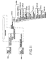
- Figure 11 is a logical data flow diagram illustrating the component processes that form the driver profile recorder shown in Figure 9.
- Figure 12 is a logical data flow diagram illustrating the component processes that form the positioning program shown in Figure 9.
- Figure 13 is a logical data flow diagram illustrating the component processes that form the external condition monitoring program shown in Figure 9.
- Figure 14 is a logical data flow diagram illustrating the component processes that form the route guidance application shown in Figure 9.
- Figure 15 is a logical data flow diagram illustrating the component processes that form the route calculation application shown in Figure 14.
- Figure 16 is a logical data flow diagram illustrating the component processes that form the obstacle detection program shown in Figure 9.
- Figure 17 show a logical data flow diagram illustrating the component processes that form the object identifier program shown in Figure 16.
- Figure 18 is a logical data flow diagram illustrating the component processes that form the image processing program shown in Figure 17.
- Figure 19 is a logical data flow diagram illustrating components of the critical vehicle control programming shown in Figure 9.
- Figure 20 is a logical data flow diagram illustrating components of the warning decision application shown in Figure 9.
- Figure 21 is a logical data flow diagram illustrating the component processes that form the vehicle-user device manager shown in Figure 9.
- Figure 22 is a logical data flow diagram illustrating the components that form the automated mayday system shown in Figure 6.
- Figure 23 is a logical data flow diagram illustrating the component processes that form the manual mayday application shown in Figure 22.
- Figure 24 is a logical data flow diagram illustrating the component processes of the external communication manager system shown in Figure 22.
- Figure 25 is a logical data flow diagram illustrating the component processes that form the external reporter application shown in Figure 24.
- Figure 26 is a logical data flow diagram illustrating the component processes that form the concierge application shown in Figure 24.
- Figure 27 is a logical data flow diagram illustrating the component processes that form the obstacle/collision warning application shown in Figure 6.
- Figure 28 is a logical data flow diagram frustrating the component processes that form the enhanced curve warning application shown in Figure 6.
- Figure 29 is a logical data flow diagram illustrating the component processes that form the drive recorder shown in Figure 2.
- an in-vehicle computing architecture that enables the provision of safety-enhancing and convenience-enhancing features and services in a vehicle.
- the in-vehicle computing architecture is a high-integrity, non-stop system that meets stringent requirements for the reliability of hardware, operating software, and key applications.
- One of the features enabled by the in-vehicle computing architecture is a vehicle-environment modeling program.
- the vehicle-environment modeling program maintains a data model that precisely describes the vehicle, the past, present, and predicted future environment around the vehicle, and where the vehicle is located relative to the environment around the vehicle.
- the description of the vehicle in the data model includes a description of the conditions and status within the vehicle, including the driver and passengers.
- the data model description of the environment around the vehicle includes roadway geometry, road conditions, traffic conditions, obstacles, and other vehicles.
- FIG. 1 there is a diagram illustrating a vehicle 10.
- the vehicle 10 is located in a multiple vehicle environment 12.
- Located in the multiple vehicle environment 12 are a plurality of other vehicles 11A, 11B, 11C ...11n.
- the multiple vehicle environment 12 includes a road network 13.
- the geographic region may correspond to a metropolitan or rural area, a state, a country, or combinations thereof.
- the multiple vehicle environment 12 may include more than one such geographic region.
- the multiple vehicle environment 12 may also include off-road portions of a geographic region.
- the service provider 16 Located in the multiple vehicle environment 12 is at least one service provider 16.
- the service provider 16 provides remote services for the vehicle 10 when the vehicle 10 is located in the multiple vehicle environment 12.
- the service provider 16 may provide other functions as well, as described below.
- the service provider 16 may provide similar or identical remote services for some, but not necessarily all, of the other vehicles 11 located in the multiple vehicle environment 12.
- the services provided by different service providers may be similar or may be different.
- the service provider 16 and the vehicle 10 communicate with each other over a data network 18.
- the other vehicles 11 in the multiple vehicle environment 12 that are serviced by the service provider 16 may also communicate with the service provider 16 over the data network 18.
- the data network 18 is linked to and/or interfaces with other networks 19. These other networks may include the Internet, telecommunications networks, private intranets, and so on.
- the data network 18 may use any suitable protocols for information exchange between parties on the network. These suitable protocols include any that are currently available, such as TCP/IP, as well as protocols that become available in the future. More than one protocol may be used in the data network 18 provided that appropriate conversion is used.
- At least part of the data network 18 is comprised of a wireless portion 20.
- the wireless portion 20 enables two-way communication between the vehicle 10 and the service provider 16 while the vehicle 10 is located anywhere in the multiple vehicle environment 12.
- the wireless portion 20 may be implemented by any suitable form of wireless communications, including cellular, PCS, satellite, FM, radio, or technologies that may be developed in the future.
- the other vehicles 11 in the multiple vehicle environment that are serviced by the service provider 16 may also use the same means of wireless communication 20 to communicate over the data network 18 with the service provider 16.
- other vehicles that are serviced by the service provider 16 may use other means of wireless communication to connect to the data network 18 and/or communicate with the service provider 16.
- the wireless portion 20 may include one or more transmitters 22, such as a transponder tower, an antenna tower, an FM tower, satellites, or other suitable means.
- the transmitters 22 include an appropriate communication link 28 to the service provider 16. This link 28 may be land-based or may be wireless.
- the transmitters 22 include suitable technology that enables two-way communication between the service provider 16 and the plurality of vehicles 11.
- the vehicle 10 is equipped with a computing architecture, as described in more detail below.
- the computing architecture in the vehicle provides for networking of the computer systems internal to the vehicle as well as networking of the systems in the vehicle with computer systems outside the vehicle, such as the data network 18.
- Some or all of the other vehicles in the multiple vehicle environment 12 may be equipped similarly or identically to the vehicle 10.
- the vehicle 10 is representative of a class of vehicles equipped with network-computer-architecture enhancements.
- Figures 2 and 3 show a logical block diagram of the new computing system architecture (labeled generally 100), for a land-based vehicle 10.
- the architecture shown in Figures 2 and 3 provides an organization for the various computing systems in the vehicle that support the vehicle hardware and other systems and equipment in the vehicle 10.
- the computing systems in the vehicle 10 include both hardware and software components.
- the in-vehicle computing architecture 100 facilitates operation of the various hardware and software equipment and systems in the vehicle, thereby enabling them to work together in a coordinated manner. Further, the in-vehicle system 100 enables the provision of enhanced features and services in the vehicle.
- a plurality of software programs and applications provide various features and functions.
- the plurality of software programs and applications run on a plurality of processors 212 included in the vehicle 10.
- the processors 212 are interconnected in a data network so that the plurality of programs and applications can be executed on one or more of the plurality of processors 212.
- the in-vehicle computing architecture 100 provides a framework that enables different programs and applications in the vehicle 10 to share information while avoiding conflicts.
- the computing architecture 100 accomplishes this, in part, by establishing priorities and providing a consistent architecture.
- Figures 2 and 3 show that the in-vehicle computing architecture 100 organizes the programs and applications running in the vehicle 10 into two groupings.
- a first grouping 200 shown in Figure 2, relates to driver assistance applications and systems.
- a second grouping 300 shown in Figure 3, relates to mobile information and services.
- the programs and applications in these two groupings can share data. However, the programs and applications in these two groupings are logically separated from each other by a first or internal firewall system 214.
- the internal firewall system 214 preserves the driver assistance applications and systems 200 from interference from or resource contention with the mobile information and services applications and systems 300.
- the in-vehicle computing architecture 100 also provides a second or external firewall system 219.
- the external firewall system 219 provides protection for the entire in-vehicle computing system architecture 100, including both the driver assistance systems 200 and the mobile services and information systems 300, from external interference from the outside world.
- the in-vehicle computing architecture 100 also provides for redundancies and backups of certain functions and equipment in the vehicle.
- the in-vehicle computing architecture 100 enables certain functions and equipment to be afforded priority in a networked system environment.
- the in-vehicle computing architecture 100 enables the provision of safety-enhancing and convenience-enhancing equipment and services in the vehicle 10.
- the vehicle 10 includes a first group of sensors 202 and a second group of sensors 204.
- the first group of sensors 202 monitors the environment and conditions around the vehicle 10.
- the second group of sensors 204 monitors the mechanical systems 208 of the vehicle.
- Vehicle-environment modeling programming 210 is implemented on one or more of the plurality of networked programmable processors 212.
- the vehicle-environment modeling programming 210 receives the outputs of the first group of sensors 202 and the second group of sensors 204 via a sensor (or first) programming interface 216.
- the vehicle-environment modeling programming 210 also uses data from a geographic database 220.
- the geographic database 220 includes data that represent geographic features in the geographic area around the vehicle.
- the vehicle-environment modeling programming 210 uses the data from the geographic database 220 in combination with the outputs from the first and second groups of sensors 202 and 204 to generate and continuously update a data model (shown at 213 in Figure 5, below) of the vehicle 10 in its environment.
- the data model 213 represents a fusion of the sensor data and the data from the map database.
- the data model generated by the vehicle-environment modeling programming 210 is used by vehicle operations applications 224.
- the vehicle operations applications 224 are implemented on one or more of the plurality of networked programmable processors 212.
- the vehicle operations applications 224 analyze the data model and determine desired vehicle operation.
- the vehicle operations applications 224 provide outputs to a critical vehicle control program 230.
- the end-user-driver provides input to a driver interface 250 to indicate desired vehicle operation.
- the end-user-driver inputs received by the driver interface 250 are provided to the vehicle operations applications 224, the data modeling program 210, and the critical vehicle control program 230.
- the critical vehicle control program 230 uses the outputs from the vehicle operations programming 224 and the driver interface 250, resolves any ambiguities or conflicts, determines a single desired vehicle operation, and translates the desired operation to commands for one or more of the vehicle mechanical systems 208 to effect the single desired vehicle operation. These commands are transmitted from the critical vehicle control program 230 to operate the vehicle mechanical systems 208 via a control (or second) programming interface 258.
- the critical vehicle control program 230 also includes an interface to a communications manager 260. Based upon commands from the critical vehicle control program 230, data may be transmitted to the service facility 16 (in Figure 1) or other necessary destinations such as directly to other vehicles or to roadside equipment. The transmission of data to the service facility is subject to the priorities established between the driver assistance systems and the mobile services and information systems.
- the critical vehicle control program 230 also includes an interface to a vehicle-to-user device manager 270. Based upon commands from the critical vehicle control program 230, data, such as warning or other advice, may be forwarded to the driver. This data may be forwarded to the driver from the vehicle-to-user device manager 270 via the driver interface 250. The priorities of these warnings are based upon the relative priorities established between the driver assistance systems and the mobile services and information systems.
- the in-vehicle architecture also supports another group of applications 324 that relate to mobile services and information.
- the mobile services and information applications 324 provide convenience, entertainment, business, comfort, and other features.
- the mobile services and information applications 324 are not as critical as the driver assistance applications 224.
- the mobile services and information applications 324 may be provided in general with lower priorities for the computing and communications resources of the vehicle than the driver assistance applications 224. Nonetheless, during normal operation of the vehicle, there are usually sufficient computing resources to support some or all of the mobile services and information applications 324.
- the mobile services and information applications 324 receive user input from a user interface 350.
- the user interface 350 may include some of the same equipment and hardware as the driver interface 250.
- the user interface 350 may include additional interface equipment.
- the user interface 350 includes means by which passengers, as well as the driver, can provide input to the mobile services and information applications.
- the mobile services and information applications 324 may use some of the data from the same sensors 202 and 204 used to support the driver assistance applications 224. In addition, the mobile services and information applications 324 may be supported by additional sensors 304.
- the mobile services and information applications 324 receive input directly from the user interface 350 and the sensors 304, or alternately, the mobile services and information applications receive some of their input via one or more processing subsystem programs 310 executed on one or more of the plurality of networked processors 212.
- the mobile services and information applications 324 may also get information from the driver assistance systems 200.
- the mobile services and information applications 324 provide outputs to a vehicle interface 330.
- the vehicle interface 330 resolves any conflicts among commands from the mobile services and information applications 324 and provides appropriate commands to the equipment 308 under the control of the mobile services and information applications 324.
- the vehicle interface 330 also includes an interface to the communications manager 260 and the drive recorder 225 and vehicle-user device manager 270.
- the first type of sensor devices 202 includes one or more different kinds of hardware or apparatuses that sense the position of the vehicle in its environment and features and conditions in the environment around the vehicle 10. Included among the sensor devices 202 are apparatuses that detect stationary or moving objects physically in the vicinity around the vehicle 10. For example, the sensor devices 202 sense and detect other vehicles, pedestrians, buildings, lampposts, bridge abutments, lane barriers, fences, traffic signals, traffic signs, and so on. The sensor devices 202 not only detect the presence of objects around the vehicle 10, but also, the sensor devices 202 detect the positions and sizes of these objects relative to the vehicle 10.
- sensor devices may be used and the present embodiment is not restricted to any particular type of sensor or combination of sensors.
- sensor devices that may be used to perform the desired functions include a radar system 202(7), a video camera CCD 202(6), a laser device 202(5), an infrared sensor 202(15), as well as other devices.
- the physical position of the vehicle includes its geographic position (e.g., latitude and longitude).
- the physical position of the vehicle also includes its orientation, altitude, inclination, and so on.
- the devices that perform this detection may include a global positioning system 202(1), a gyroscope 202(2), a yaw sensor 202(3), a variometer 202(8), and a 3-axis accelerometer 202(4), as well as other devices.
- the sensor devices 202 also include apparatuses that sense road conditions, such as moisture and traction.
- the sensor devices 202 also include apparatuses that sense and detect weather and meteorological conditions, such as temperature, precipitation, barometric pressure, humidity, wind speed, ambient light, visibility, and so on.
- weather and meteorological conditions such as temperature, precipitation, barometric pressure, humidity, wind speed, ambient light, visibility, and so on.
- Various kinds of devices may be used and the present embodiment is not restricted to any particular type of device. Examples of such devices include a barometer 202(9), an external light sensor 202(10), a hydrometer 202(11), a precipitation sensor 202(12), a temperature sensor 202(13), a friction sensor 202(14), as well as other devices 202(n).
- the second type of sensor device 204 in Figure 2 includes one or more different kinds of hardware or apparatuses that sense various vehicle conditions.
- Various kinds of sensor devices may be used and the present embodiment is not restricted to any particular type of sensor.
- suitable devices include a vehicle odometer 204(1), a vehicle speedometer 203(2), a vehicle fuel gauge 204(3), a tire pressure sensor 204(4), an oil pressure sensor 204(5), an airbag status sensor 204(6), a fire extinguisher sensor 204(8), a traction control sensor 204(9), an engine control sensor 204(12), a stability control sensor 204(14), a seatbelt tensor sensor 204(15), a drowsiness monitor 204(10), and passenger seat sensors 204(11) that determine the presence and position of each passenger.
- the sensor devices 204 also include a vehicle diagnostic sensor 204(7). Other sensors in addition to these may be included and used.
- Figure 5 shows some of the component programs that form the vehicle-environment modeling programming 210 shown in Figure 3. These programs are implemented by software running on one or more of the plurality of processors 212 in Figure 3. These component applications use the outputs from the various sensor devices 202 and 204 as well as data from the geographic database 220. In one embodiment, the outputs from various sensor devices 202 and 204 and the geographic database 220 are provided to the vehicle-environment modeling programming 210 via the common programming interface 216.
- the vehicle-environment modeling programming 210 provides an output in the form of the data model 213.
- the data model 213 is a representation (or picture) of the vehicle and the environment surrounding the vehicle.
- One of the properties of the data model 213 constructed by the vehicle-environment modeling programming 210 is that it is interpreted. For example, the objects in the environment surrounding the vehicle are not only detected, but an interpretation is made by the vehicle-environment modeling programming 210 as to what the detected objects are.
- the vehicle-environment modeling programming 210 uses data from the geographic database 220 as well as data from the sensors 202 and 204 to construct the data model 213.
- the data model 213 includes representations of the objects in the environment surrounding the vehicle, including the sizes of the objects, the distances of each of the objects relative to the vehicle, the speeds and accelerations of each of the objects relative to the vehicle, and so on.
- the data model 213 is dynamic.
- the data model is continuously being updated over time as the sensors acquire new data.
- the data model 213 is also continuously being updated spatially as the vehicle moves in the geographic area.
- the data model 213 is also continuously being updated as the environment around the vehicle changes, for example as other vehicles and pedestrians move in the vicinity of the vehicle.
- the vehicle-environment modeling programming 210 includes a vehicle positioning program 210(1).
- the vehicle positioning program 210(1) uses data from the sensors 202 and 204 and the geographic database 220 to determine the position, speed, and heading of the vehicle 10.
- the obstacle detection program 210(2) determines various properties of all the obstacles detected around by the vehicle by the sensors 202. Some of the properties of the obstacles determined by the obstacle detection program 210(2) include the position, size, speed, acceleration, etc., of each detected obstacle.
- the vehicle-environment modeling programming 210 also includes core programming 210(3).
- the core programming 210(3) uses the data from the map database 220.
- the map database 220 provides a highly accurate, three-dimensional representation of the roadway geometry, including features along the roadway. (In one embodiment, the map database 220 has sub-meter accuracy, although in other environments, the map database has an accuracy level that is other than sub-meter.)
- the vehicle-environment modeling programming 210 also includes programming 210(4) that monitors the status of the vehicle.
- the vehicle status programming 210(4) monitors engine speed, which gear the transmission is in, whether the headlights are on, and various other vehicle conditions.
- the vehicle-environment modeling programming 210 also includes a vehicle diagnostics application 210(5).
- the vehicle diagnostics application 210(5) monitors the operating behavior of the vehicle hardware. Based upon this monitoring, the vehicle diagnostics application 210(5) determines whether the vehicle's operation is within normal operating parameters.
- the vehicle diagnostics application 210(5) may include rules and parameter data for these purposes
- the vehicle-environment modeling programming 210 also includes a driver status program 210(6).
- This program 210(6) monitors the driver's reaction times and other characteristics of the driver to determine whether the driver's behavior indicates drowsiness, intoxication, medical problems, and so on.
- the vehicle-environment modeling programming 210 also includes driver history programming 210(7).
- This programming 210(7) logs the driver's behavior patterns over time.
- the driver history programming 210(7) is used in conjunction with the driver status programming 210(6) to determine when the driver's behavior while driving the vehicle deviates from normal patterns.
- the vehicle-environment modeling programming 210 also includes driver interface programming 210(8).
- the driver interface programming 210(8) monitors and interprets control requests by the driver that are input into the driver interface 250.
- the vehicle-environment modeling programming also includes programming 210(9) that monitors and determines passenger status.
- This programming 210(9) uses the input from the sensors 204 to determine which, if any, passenger seats are occupied, the number of passengers in the vehicle, the height and weight of each passenger, whether the passenger is occupying a baby or child seat, and other characteristics of the passengers.
- the vehicle-environment modeling programming also includes entry security programming 210(10).
- the entry security programming 210(10) acts as an entry management system. For example, the entry security programming 210(10) may disable the engine if the wrong key is used or if the wrong electronic code key is entered.
- the vehicle-environment modeling programming 210 also includes programming 210(11) that monitors the conditions external to the vehicle. This programming 210(11) monitors such conditions as temperature, humidity, wind speed, ambient light, altitude, and so on.
- the vehicle-environment modeling programming 210 also includes programming 210(12)(D) that maintains a profile of the driver.
- This programming 210(12)(D) may maintain a listing of driver preferences, information, etc., which may be used for tailoring operation of certain of the applications, as described below.
- the programming 210(12)(D) stores data about the driver preferences in a driver profile data file 215(D).
- This data file 215(D) is stored so that it is accessible to other applications and programs in the vehicle.
- the driver profile data file 215(D) also may include other information about the driver, such as age, physical handicaps, if any, medical history, and so on.
- the vehicle-environment modeling programming 210 may also include programming 210(12)(P) that maintains profiles of each of the passengers.
- This programming 210(12)(P) may include age, physical handicaps if any, medical history, and passenger preference settings, such as seat, temperature, user interface, etc.
- the programming 210(12)(P) stores data about the passengers in a passenger profile data file 215(P). This data file 215(P) is stored so that it is accessible to other applications and programs in the vehicle.
- the vehicle-environment modeling programming 210 also includes image processing programming 210(13).
- the image processing programming 210(13) uses the data from the sensor devices that obtain visual images of the environment around the vehicle, such as the CCD (camera) 202(6), the radar system 202(7), the laser 202(5), and the infrared sensor 202(15).
- the image processing programming 210(13) analyzes the visual images received from these devices in order to identify objects in the images.
- the image processing programming 210(13) may use known techniques to identify objects in images. Based upon this analysis, the image processing programming 210(13) provides a list of found objects as an output that can be used by other programs and applications in the vehicle.
- the vehicle-environment modeling programming 210 also includes object identifier programming 210(14).
- the object identifier programming 210(14) receives the list of found objects output from the image processing programming 210(13) and attempts to identify objects by type, size and speed.
- the object identifier programming 210(14) provides a data output to other programs and applications in the vehicle.
- the vehicle-environment modeling programming 210 may also include other programs 210(n).
- FIG 6 shows some of the driver assistance applications 224 shown in Figure 3. These applications use the data model output 213 from the vehicle-environment modeling programming 210 and the driver interface 250.
- the driver assistance applications 224 also use information from the driver profile data file 215(D). As mentioned above, the profile data file 215(D) stores driver preferences and desired operating characteristics.
- the driver assistance applications 224 provide outputs to the critical vehicle control program 230.
- driver assistance applications 224 described below are not intended to be an exhaustive listing of all the kinds of applications that can be enabled by the disclosed in-vehicle architecture. Other applications can also be provided. Similarly, not all of the driver assistance applications described below are necessarily provided in each vehicle. Various combinations of applications and various combinations of features and functions may be provided.
- driver assistance applications 224 that may be provided is an adaptive cruise control system and application 224(1).
- the adaptive cruise control system and application automatically maintains a desired following distance by managing vehicle speed as well as braking. This application is described in more detail in connection with Figures 9-21, below.
- ABS anti-lock brake system
- This application uses the information from the data model 213 relating to wheel speed, road conditions, precipitation, and desired braking to provide an output for the braking to be applied to each vehicle wheel.
- the driver assistance applications 224 also include an engine control application 224(3). This application uses the information relating to vehicle status to provide an output for controlling overall engine operation, including engine speed.
- the driver assistance applications 224 also include a smart throttle/transmission application 224(5). This application uses the information from the data model 213 relating to road grade, engine load, desired acceleration, and so on, to determine the appropriate transmission gear and shift points.
- the driver assistance applications 224 also include a smart headlights application 224(6).
- This application uses information from the data model 213 relating to the vehicle environment, including other vehicles, vehicle orientation, the intended route, the road configuration along the intended route, and so on. This application provides an output that controls the headlights to better illuminate around and ahead of the vehicle.
- the output of the smart headlights application 224(6) is used to automatically aim the headlights around curves ahead of the vehicle.
- the output of the smart headlights application 224(6) may also be used to automatically aim the headlights upward as hills are approached.
- the smart headlights application 224(6) may also be used to automatically adjust the high beams, automatically turn on and off the headlights, automatically turn on the driving lights and fog lights, automatically turn on directional signals, and so on.
- the driver assistance applications 224 also include a traction control application 224(4). This application uses the information from the data model 213 relating to vehicle speed, engine speed, road conditions, and desired operation to provide outputs for the torque to be applied to each wheel.
- the driver assistance applications 224 also includes warning system applications 224(7).
- the warning system applications 224(7) may include an obstacle warning application 224(7)(1), a curve warning application 224(7)(2), an intersection collision warning application 224(7)(3), a fire warning application 224(3)(4), a lane departure warning application 224(7)(5), a collision warning application 224(7)(6), and a mayday warning application 224(7)(7).
- the obstacle warning application 224(7)(1) uses the information from the data model 213 relating to the speed and direction of the vehicle and the speeds and directions of the obstacles around the vehicle. This application provides an output to warn the driver of these obstacles.
- the curve warning application 224(7)(2) uses the information from the data model 213 about curves in the road ahead of the vehicle, the road conditions, the weather conditions, the ambient light, and the vehicle's position and speed relative to curves in the road ahead.
- the curve warning application 224(7)(2) provides an output to give the driver with a warning, if appropriate.
- the intersection collision warning application 224(7)(3) uses the information from the data model 213 about the speed and direction of the vehicle and the speeds and directions of the other vehicles around the intersection to provide a warning of possible collisions with other vehicles.
- the fire warning application 224(7)(4) uses the information from the data model 213 relating to vehicle status and diagnostics to provide an output to warn about a detected fire in the vehicle.
- the lane departure warning application 224(7)(5) uses the information from the data model relating to the vehicle's coordinates and the lane coordinates to provide an output warning of possible departure by the vehicle from the lane.
- the collision warning application 224(7)(6) uses the information from the data model relating to the vehicle's coordinates and coordinates of other objects around the vehicle to provide an output warning of possible collision with other objects.
- the mayday warning application 224(7)(7) provides a warning informing the driver when the automatic mayday application 224(5) has been activated to send a warning.
- the driver assistance applications 224 also include a ride-smoothing application 224(8). This application uses the information from the data model 213 relating to road conditions and vehicle speed to provide outputs to adjust the vehicle suspension characteristics.
- the driver assistance applications 224 also include a stability application 224(9).
- This application uses information from the data model 213 relating to vehicle status and vehicle environment. This application provides an output to adjust vehicle operation to prevent overturning.
- the driver assistance applications 224 also include an automatic door unlock application 224(10).
- This application uses the information from the data model relating to vehicle status, driver status, and passenger status to automatically lock the vehicle doors when a collision is imminent and then automatically unlock the vehicle doors when the vehicle has safely come to a stop after a collision.
- This application may also lock all the vehicle doors when the driver and passengers are all inside the vehicle and the vehicle is ready to move.
- the driver assistance applications 224 also include a braking assistance application 224(11). This application uses information from the data model 213 relating to vehicle status and vehicle environment. This application provides an output to assist the function of the vehicle brakes.
- the driver assistance applications 224 also include an intersection collision avoidance application 224(12). As the vehicle approaches an intersection, this application 224(12) uses information about the road configuration to automatically command the vehicle to avoid a collision at an intersection that the vehicle is approaching. This application uses information from the data model 213 relating to the vehicle position and direction, as well as data relating to the road configuration. The road configuration information can be used to provide this function even at intersections that may not be visible to the driver. The road condition information is also used by this application to determine a safe collision avoidance maneuver (i.e., so that a maneuver that avoids one object does not hit another object.) This application may also use information about the positions and planned routes of the other vehicles that are approaching an intersection ahead of the vehicle. Using this information, the application also determines maneuvers that avoid collisions with other vehicles that are also approaching the intersection. The information relating to the planned routes of the other vehicles may be obtained from the service provider 16 or directly from the other vehicles.
- the driver assistance applications 224 also include a collision avoidance application 224(13). This application uses information about the road configuration, road furniture, and about obstacles detected around the vehicle and provides an output that can be used to automatically command the vehicle to avoid obstacles.
- the driver assistance applications 224 also include a security application 224(14). This application uses the information from the data model 213 relating to the vehicle status, driver status, and passenger status. This application uses this information to prevent unauthorized use of the vehicle, to provide outputs to request assistance in the event of unauthorized use of the vehicle, and so on.
- the driver assistance applications 224 also include an automated mayday application 224(15). This application uses the information from the data model 213 relating to vehicle and driver condition to provide an output to the communications manager 260 to request emergency assistance. This application is described in more detail in connection with Figures 22-25, below.
- the driver assistance applications 224 also include a fire extinguisher application 224(16). This application uses information from the data model 213 relating to vehicle status and environmental conditions. This application provides an output to operate a fire extinguisher system under appropriate conditions.
- the driver assistance applications 224 also include a pollution control application 224(17).
- This application uses information from the data model 213 relating to vehicle status and vehicle environment. This application provides output commands to the vehicle hardware systems to minimize pollution under various driving conditions. For example, using information about the altitude, barometric pressure, wind speed, ambient light conditions, and temperature, the pollution control application 224(17) modifies engine operation to minimize pollution.
- the driver assistance applications 224 also include an external reporting application 224(18).
- This application uses information from the data model 213 relating to the vehicle status and vehicle environment. This application provides an output to report on certain vehicle and/or environment conditions. For example, if the sensors detect ice or snow on the road, the external reporting application 224(18) reports information about the amounts and locations of the ice or snow to the service provider 16, which in turn may send messages to other vehicles travelling along the road so that the other vehicles can adjust their operation to account for the ice or snow.
- the driver assistance applications 224 also include a vision enhancement application 224(19).
- This application uses information from the data model 213 relating to vehicle status and vehicle environment. This application provides an output to provide additional information to the driver about conditions around the vehicle.
- the vision enhancement application 224(19) uses information from the sensors, such as the radar 202(7), to display objects around the vehicle to the driver when the visibility around the vehicle is poor.
- the driver assistance applications 224 also include a drowsiness warning application 224(20). This application uses information from the data model 213 relating to driver status, vehicle status, and driver history. This application provides an output to warn the driver in the event driver behavior indicates that the driver is drowsy.
- the driver assistance applications 224 also include a warning decision application 224(22). This application uses information from the warning applications 224(7), the vehicle status, and the driver status to determine whether to provide the driver with a warning message, to coordinate provision of multiple warning messages, and to forward information about warnings to the communication manager 260 for relay to the service provider 16, when appropriate. This application is described in more detail in connection with Figure 20, below.
- the driver assistance applications 224 may include additional programs 224(n). Also, additional programs may be added as upgrades, updates, or entirely new applications. Because the applications 224 operate from the data model 213 and not directly from the sensors 202 and 204, new applications may be added by means of a software upgrade.
- FIG. 2 shows that the vehicle 10 includes various hardware systems 208.
- These hardware systems 208 include the various mechanical, hydraulic, and electrical systems that move and stop the vehicle and provide for driver and passenger safety. These mechanical, hydraulic, and electrical systems 208 operate under the control of actuators or other controller devices.
- the actuators and controller devices receive commands from the critical vehicle control program 230 through the command programming interface 258.
- Vehicle embodiments may include hardware systems in addition to those shown in Figure 7 and likewise there may be vehicle embodiments that do not include all the hardware systems shown in Figure 7.
- these hardware systems 208 are operated by commands from the critical vehicle control program 230. Included among these systems are an engine control system 208(1), a transmission actuator 208(2), steering actuators 208(3), brake actuators 20(4), airbag actuators 208(5), seatbelt adjustment actuators 208(6), an accelerator actuator 208(7), a mirror dimmer controller 208(8), suspension actuators 208(9), a headlight controller 208(10), and warning light actuators 208(11).
- Other mechanical, hydraulic, and electrical systems 208(n) may be operated via commands from the critical vehicle control program 230.
- Figure 8 shows some of the specific mobile services and information applications 324 that are indicated in Figure 3. These applications 324 may be provided entirely on-board the vehicle, entirely off-board the vehicle, or may be hybrid applications that are provided in part on-board and in part off-board the vehicle.
- the mobile services and information applications 324 are shown to receive data from the vehicle sensors 304 and the mobile services and information geographic database 320.
- the geographic database 320 used by the mobile services and information programming may be the same as the geographic database (i.e., 220 in Figure 2) used by the driver assistance programs 210 and 224. Alternatively, the mobile services and information programming and the driver assistance programming may use different databases.
- the geographic database 320 used by the mobile services and information programming includes information that can be used to calculate routes, provide route guidance, find desired destinations, find desired points of interest, and provide other services.
- the geographic database 220 used by the driver assistance programming is used to build a detailed three-dimensional model of the environment around the vehicle.
- the mobile services and information applications 324 also receive input from the user interface 350.
- the mobile services and information applications 324 also receive data from the driver assistance systems 200 across the firewall 214.
- Figure 8 shows the mobile services and information applications and systems in one exemplary vehicle embodiment. Other embodiments may include applications and systems in addition to those shown in Figure 8. Also, some embodiments may not include all the applications and systems shown in Figure 8 or may include different combinations of applications and systems.
- the mobile services and information applications 324 may include route guidance 324(1), route calculation 324(2), content services 324(3), entertainment 324(4), a remote interface 324(5), theft protection services 324(6), office-in-the-car services 324(11), car environment controls 324(7), car care reminders 324(8), Win CETM applications 324(10) (or other visiting operating systems applications), real-time traffic services 324(9), concierge services 324(12), electronic fee payment 324(14), cellphone management 324(13), and a manual mayday application 324(15), as well as other services 324(n). These services and applications provide outputs to the vehicle interface 358 (shown in Figure 3).
- Examples of services or systems that provide some of the features of the mobile services applications or similar features include AutoPCTM, MONETTM, Tegaron InfoTM, SmarTravelerTM, and OnStarTM.
- One of the applications that can be implemented using the disclosed vehicle computing architecture is an adaptive cruise control system.
- the hardware and connectivity needs of the adaptive cruise control system are supported by the physical portion of the in-vehicle computing architecture platform.
- the adaptive cruise control feature automatically adjusts the speed and direction of the vehicle to provide for proper intervals between the vehicle and other vehicles and obstacles.
- This feature is provided by a combination of components, including software and hardware components in the mobile information and services portion of the in-vehicle computing architecture as well as software and hardware components in the driver assistance portion.
- the adaptive cruise control feature is described in connection with Figures 9-21.
- FIG. 9 there is shown a logical block diagram showing the major components that implement the adaptive cruise control feature.
- the adaptive cruise control application 224(1) receives data from and outputs data to other systems, programs and applications included in the in-vehicle computing architecture. These other systems, programs and applications are described in the sections that follow.
- the driver interface system 250 includes a monitoring process 250(A).
- the monitoring process 250(A) monitors inputs from various driver interface hardware components.
- the inputs that the process 250(A) monitors may include input from the brake pedal 251(1), input from the steering wheel 251(2), input from the clutch pedal 251(3), input from the accelerator 251(4), input from the headlights switch 251(5), input from the turn signal handle 251(6), input from the windshield wiper switch 251(7), input from the horn 251(8), input from the cruise control switch 251(9), and well as from other driver interface hardware components.
- the monitoring process 250(A) collects the data from these various inputs and provides an output to the driver history program 210(7) and the drive recorder 225.
- the driver history program 210(7) and the drive recorder 255 use the data from the monitoring process 250(A) to store respective records in memories in the vehicle.
- the monitoring process 250(A) also provides an output to the driver status program 210(6).
- the monitoring process 250(A) also outputs the data collected from the various driver interface components to a decision process 250(B). These outputs provided to the decision process 250(B) represent physical manipulations by the driver of the driver interface components.
- the decision process 250(B) receives each of these outputs from the monitoring process 250(A) and provides a translation into data indicating a desired vehicle operation. For example, a signal from a sensor associated with the brakes indicates the force applied by the driver to the brake pedal (or other brake component). This signal is collected by the monitoring process 250(A) and provided to the decision process 250(B) that provides an output indicative of a desired force to be applied by the brakes.
- the decision process 250(B) provides an output to a send command process 250(C).
- the send command process 250(C) provides data outputs to the adaptive cruise control application 224(1).
- the driver interface system 250 provides data to the adaptive cruise control application 224(1) indicating whether the driver has turned on or off the adaptive cruise control feature. Additionally, the driver interface 250 may also provide data to the adaptive cruise control application 224(1) indicating distance settings desired by the driver which will be used instead of default settings.
- the driver interface system 250 also provides data to other components and systems in the in-vehicle computing architecture, including the critical vehicle control program 230 and the external condition monitor program 210(11), among others.
- the driver interface 250 may also include a display controller 251(10), a heads-up controller 251(11), a voice generator 251(12), and a warning light actuator 251(13). These components are described below in connection with the vehicle-user device manager 270.)
- driver profile recorder program 210(12)(D) another of the programs from which the adaptive cruise control application 224(1) receives data is the driver profile recorder program 210(12)(D).
- Figure 11 shows the component that forms the driver profile recorder program 210(12)(D).
- the driver profile data file 215(D) receives driver preferences, information, etc., from the driver interface 250.
- the information in the Jriver profile data file 215(D) is made available to the other applications, components, and systems.
- the adaptive cruise control application 224(1) obtains data from the driver profile data file 215(D) indicating the identity of the driver as well as the driver's preferences, such as speed, driving intervals, preferred types and timing of warnings, etc.
- the positioning program 210(1) is part of a vehicle positioning system that includes software and hardware components.
- Figure 12 shows the component processes included in the positioning program 210(1).
- the positioning program 210(1) includes a process 210(1)(A) that fuses data from sensors.
- the process 210(1)(A) receives data from sensors, such as the GPS 202(1), the gyroscope 202(2), the yaw sensor 202(3), the speedometer 204(2), the odometer 204(1), the variometer 202(8), and the 3-axis accelerometer 202(4).
- the process 210(1)(A) then fuses the data and provides a fused collection of the data to a position calculation process 210(1)(B).
- the position calculating process 210(1)(B) receives the fused collection of data from the fusing process 210(1)(A).
- the position calculating process 210(1)(B) also receives data from the map database 220.
- the position calculating process 210(1)(B) may also receive from the object identifier application 210(14) data indicating objects identified around the vehicle.
- the position calculating process 210(1)(B) may also receive from the route calculation application 324(2) data indicating the calculated route that the vehicle is following.
- the position calculating process 210(1)(B) calculates the position, speed, and heading of the vehicle 10 using data from the fusing process 210(1)(A), the map database 220, the object identifier application 210(14), and the route calculation application 324(2).
- the position calculating process 210(1)(B) provides data to the adaptive cruise control application 224(1) indicating the position, speed, and heading of the vehicle 10.
- the position calculating process 210(1)(B) also feeds back the current calculated position to the fusing process 210(1)(A) which uses the current calculated position in connection with a subsequent iteration of the fusion process.
- the position calculating process 210(1)(B) also provides data indicating the position, speed, and/or heading of the vehicle 10 to other applications, such as the obstacle detection application 210(2), the automated mayday application 224(15), the concierge services application 324(12), the manual mayday application 324(15), the route guidance application 324(1), and the drive recorder 225.
- other applications such as the obstacle detection application 210(2), the automated mayday application 224(15), the concierge services application 324(12), the manual mayday application 324(15), the route guidance application 324(1), and the drive recorder 225.
- FIG. 13 shows the component processes that form the external condition monitor program 210(11).
- the external condition monitor program 210(11) includes a monitoring process 210(11)(A).
- the monitoring process 210(11)(A) receives barometric data from the barometer 202(9), data indicating the status of the windshield wipers and headlights from the driver interface 250, data indicating the external light level from the external light sensor 202(10), data indicating the external temperature from the external temperature gauge 202(13), data indicating the humidity from the hydrometer 202(11), data indicating the current visibility ranges from the image processing program 210(13), data indicating the precipitation type and level from the precipitation monitor 202(12), data indicating the vehicle status from the vehicle status program 210(4), and data, such as road condition warnings, from the content services 324(3).
- the sensor data received by the monitoring process 210(11)(A) may also be used by other applications in the vehicle that need such data. It is also noted that uncorrelated sensor information can be made available to any and all applications as they need it. There may be cases when an application only needs a certain piece of sensor data and does not required the correlated version. Both the correlated and uncorrelated data are used when forming the data model.
- the monitoring process 210(11)(A) may provide some or all of the data it receives to other in-vehicle applications, including the adaptive cruise control application 224(1), the braking assistance application 224(11), the collision avoidance application 224(13), the collision warning application 224(7)(6), the critical vehicle control program 230, the intersection collision avoidance application 224(7)(3), the obstacle warning application 224(7)(1), and the warning decision application 224(22).
- This monitoring process 210(11)(A) also monitors the operational status of each of the sensor components 202, 204, and 304 that provides data to it.
- the monitoring process 210(11)(A) provides the data relating to visibility, such as precipitation and light levels, to a visibility calculation process 210(11)(B).
- the process 210(11)(B) calculates the visibility and provides output data indicating the visibility to the adaptive cruise control application 224(1), the braking assistance application 224(11), the collision avoidance application 224(13), the collision warning application 224(7)(6), the critical vehicle control program 230, the intersection collision avoidance application 224(7)(3), the obstacle warning application 224(7)(1), and the warning decision application 224(22).
- the visibility calculating process 210(11)(B) also provides the data indicating the visibility to the drive recorder 225.
- the visibility calculating process 210(11)(B) also provides the data indicating the visibility to the external reporting application 224(18) so that it can be transmitted to the service facility 16 and relayed to other vehicles.
- the monitoring process 210(11)(A) also provides the data relating to road surface conditions, such as external temperature, precipitation type and level, and barometric pressure to a process 210(11)(C) that calculates a road surface conditions parameter.
- This road surface condition calculating process 210(11)(C) provides output data indicating the road surface condition parameter to the adaptive cruise control application 224(1), the braking assistance application 224(11), the collision avoidance application 224(13), the collision warning application 224(7)(6), the critical vehicle control program 230, the intersection collision avoidance application 224(7)(3), the obstacle warning application 224(7)(1), and the warning decision application 224(22).
- the process 210(11)(C) also provides the data indicating the road surface conditions to the drive recorder 225.
- the road surface condition calculating process 210(11)(C) also provides the data indicating the road surface conditions to the external reporting application 224(18) so that it can be transmitted to the service facility 16 and relayed to other vehicles.
- route guidance application 324(1) another of the applications from which the adaptive cruise control application 224(1) receives data is the route guidance application 324(1).
- the route guidance application 324(1) operates in conjunction with the route calculation application 324(2).
- Figure 14 shows the component processes that form the route guidance application 324(1) and
- Figure 15 shows the component processes that form the route calculation application 324(2).
- the user selects a desired destination location using the user interface 350.
- the user may also select an origin location using the user interface 350, or alternatively, the current position of the vehicle may be specified as the origin location by default.
- Data indicating the desired destination location and the origin location are provided to a geocoding process 210(15).
- the geocoding program 210(15) determines the positions of the origin location and destination location relative to the data in the geographic database 320.
- the geocoding program 210(5) provides a data output indicating the positions of the origin location and destination location relative to the geographic database 320 to a route calculation process 324(A) which is part of the route calculation application 324(2).
- the geocoding process 210(15) may also be part of the route calculation application 324(2) or may be a standalone process.
- the route calculation process 324(2)(A) uses data from the geographic database 320, calculates one or more possible routes.
- the route calculation process 324(2)(A) provides a data output that defines the one or more possible calculated routes.
- the data output from the route calculation process 324(2)(A) is provided to a data storage 324(2)(B).
- a route selection process 324(2)(B) receives the data that defines the one or more calculated routes.
- the selection process 324(2)(B) may also receive data that indicates current traffic conditions from the real-time traffic application 324(9).
- the selection process 324(2)(B) also receives data that indicates the driver's preferences from the driver profile program 210(12)(D). Using all these inputs, the route selection process 324(2)(B) selects one of the calculated routes.
- the route selection process 324(2)(B) provides a data output that defines the selected calculated route to the drive recorder 225.
- the data that defines the selected calculated route is also provided by the route selection process 324(2)(B) to the adaptive cruise control application 224(1), the positioning system 210(1), the car care reminder application 324(8), the concierge services application 324(12), and the route guidance application 324(1).
- the route selection process 324(2)(B) also provides data to the vehicle-user device manager 270 that enables the selected calculated route to be displayed to the driver via the user interface 350.
- FIG 14 shows the processes related to the route guidance application 324(1).
- the route guidance application 324(1) includes a process 324(1)(A) that receives the data defining the selected route from the route calculation application 324(2) (in Figure 15).
- the route guidance process 324(1)(A) also receives from the positioning program 210(1) (in Figure 12) data that indicates the current position of the vehicle.
- the route guidance process 324(1)(A) also receives from the driver profile program 210(12)(D) (in Figure 11) data that indicates the driver's preferences related to route guidance. These preferences may include, for example, the language in which the guidance should be provided, the medium (i.e., audio, visual display, both) via which the guidance should be provided, etc.
- the route guidance process 324(1)(A) determines what kinds of route guidance should be provided to the driver and when such guidance should be provided. More specifically, as the vehicle approaches certain locations along the selected calculated route, route guidance about required maneuvers is provided to the driver. At appropriate locations, the route guidance process 324(1)(A) provides a data output to the vehicle-user device manager 270 indicating the kind of guidance to be provided.
- the route guidance application 324(1) also provides an output to the driver recorder 225 indicating the guidance provided.
- FIG. 10 shows another of the programs from which the adaptive cruise control application 224(1) receives data
- the obstacle detection program 210(2) operates in conjunction with the image processing program 210(13) and the object identifier program 210(14).
- Figure 16 shows the component processes that form the obstacle detection program 210(2)
- Figure 17 shows the component processes that form the object identifier program 210(14)
- Figure 18 shows the component processes that form the image processing program 210(13).
- the image processing program 210(13) includes a process 210(13)(A) that validates sensor data.
- This validation process 210(13)(A) receives data indicating visibility, precipitation, temperature, and humidity from the external conditions monitoring program 210(11).
- This process 210(13)(A) also receives raw image data from the camera 202(6).
- This process 210(13)(A) also receives data indicating object distance, speed, image, and coordinates from the radar 202(7), laser 202(5), and infrared sensors 202(15).
- the process 210(13)(A) After validating the data, the process 210(13)(A) provides image data to a consolidation process 210(13)(B). The validation process 210(13)(A) also provides data indicating the current range back to the external conditions monitoring program 210(11).
- the consolidation process 210(13)(B) provides scannable images to a process 210(13)(C) that scans for objects.
- the process 210(13)(C) that scans for objects provides a list of found objects to a process 210(13)(D) that determines the characteristics of the objects.
- This characteristics determining process 210(13)(D) also receives from the consolidation process 210(13)(B) data indicating the current range, confidence factors, speed, and distance for the found objects.
- the characteristics determining process 210(13)(D) outputs a list of found objects including their speed, distance, and confidence factors to the object identifier program 210(14).
- the object identifier program 210(14) includes a correlation process 210(14)(A) that receives the list of found objects including their speed, distance, and confidence factors from the image processing identifier program 210(13).
- the correlation process 210(14)(A) also uses data from the map database 220.
- the map database 220 includes data about objects located in the environment in which the vehicle is traveling, including the positions and sizes of the objects.
- the correlation process 210(14)(A) uses the positions of known objects from the map database 220 to attempt to identify the found objects in the list received from the image processing program 210(13).
- the correlation process 210(14)(A) provides data indicating the identified objects, along with their location and speed, to a consolidation process 210(14)(B).
- the correlation process 210(14)(A) provides a list of objects that are not in the database 220 to a classification process 210(14)(C).
- the classification process 210(14)(C) classifies the objects that were not found in the database 220 by the correlation process 210(14)(A).
- the classification process 210(14)(C) provides an output to the consolidation process 210(14)(B) that includes an identification of the objects that are not in the database 220 along with a classification of these objects.
- the consolidation process 210(14)(B) provides data indicating the objects identified in the database 220 and the objects not identified in the database 220, along with their corresponding classifications, to the drive recorder 225.
- the consolidation process 210(14)(B) also provides data indicating the objects identified in the database 220 and the objects not identified in the database 220, along with their corresponding classifications, to the obstacle warning application 224(7)(1) and the positioning program 210(1).
- the obstacle detection program 210(2) includes a process 210(2)(A) that determines whether a detected object is an obstacle.
- This process 210(2)(A) receives data from the object identifier program 210(14) that identifies detected objects including their location and speed.
- the process 210(2)(A) also receives data from the positioning program 210(1) that indicates the position and heading of the vehicle.
- the process 210(2)(A) provides an output that identifies the obstacle by type and speed.
- the process 210(2)(A) provides this data to the adaptive cruise control application 224(1), the collision avoidance application 224(13), the collision warning application 224(7)(6), the critical vehicle control program 230, the intersection collision avoidance application 224(12), the obstacle warning application 224(7)(1), and the warning decision application 224(22).
- the process 210(2)(A) also provides the data identifying the obstacle by type and speed to the drive recorder 225. If the obstacle detected by the process 210(2)(A) could affect other vehicles, data about the obstacle is also forwarded by the process 210(2)(A) to the external reporter application 224(18) so that a report can be sent to the service facility 16 and relayed to other vehicles.
- the adaptive cruise control application 224(1) includes a process 224(1)(A) that receives the previously identified data from the driver interface 250, the driver profile recorder 210(12)(D), the positioning system 210(1), route guidance program 324(1), the external condition monitor program 210(11), and the obstacle detection program 210(2).
- This process 224(1)(A) relates the data relating to obstacles around the vehicle to data relating to the vehicle.
- the process 224(1)(A) relates the relative speeds and directions of vehicles identified around the vehicle to the speed and direction of the vehicle, taking into account road surface conditions, light conditions, precipitation, tire wear, etc.
- the relating process 224(1)(A) outputs this information to a speed calculation process 224(1)(B).
- the speed calculation process 224(1)(B) calculates a desired vehicle speed.
- the speed calculation process 224(1)(B) outputs data indicating the calculated speed along with a request to adjust the vehicle speed to the critical vehicle control program 230.
- the speed calculation process 224(1)(B) continuously updates its calculation to take into account changes in the vehicle environment which might require speeding up, slowing down, or stopping the vehicle.
- the speed calculation process 224(1)(B) also outputs data indicating the calculated speed and an indication of the request to adjust the vehicle speed to the drive recorder 225. If the speed calculation process 224(1)(B) determines that the adaptive cruise control feature should be disengaged, it also outputs data indicating a request for disengagement to the warning/decision program 224(22).
- the critical vehicle control program 230 is described below in connection with Figure 19, the warning/decision program 224(22) is described below in connection with Figure 20, and the drive recorder 225 is described below in connection with Figure 29.
- FIG 19 shows the components of the critical vehicle control program 230.
- the critical vehicle control program 230 includes an integrator process 230(A).
- the integrator process 230(A) receives inputs from various programs, applications and systems in the vehicle. Specifically, the integrator process 230(A) receives data from the adaptive cruise control application 224(1) indicating a request to set the vehicle speed to a desired speed.
- Other programs, applications and systems that send requests to the integrator process 230(A) include the braking assistance application 224(11), the collision avoidance application 224(13), the collision warning application 224(7)(6), the door unlock application 224(10), the driver interface 250, the engine control application 224(3), the intersection collision avoidance application 224(12), the obstacle warning application 224(7)(1), the pollution control application 224(17), the ride smoothing application 224(18), the smart throttle and transmission application 224(5), the stability application 224(9), the traction control application 224(4), and the theft protection application 324(6).
- the integrator process 230(A) also receives diagnostic data from the vehicle diagnostics program 210(5).
- the integrator process 230(A) integrates these requests and provides a validated request list to a decision process 230(B).
- the decision process 230(B) also receives driver history data from the driver history program 210(7), data indicating the driver's preferences from the driver profile program 210(12)(D), and data indicating the driver status from the driver status program 210(6).
- the driver status data may indicate the driver's reaction times.
- the decision process 230(B) uses these inputs to provide an output in the form of an action list.
- the action list developed by the decision process 230(B) is provided to a send command process 230(C).
- the action list output by the decision process 230(B) may also be provided to a warning request process 230(D).
- the warning request process 230(D) Upon receiving an action list that requires that a warning be provided to the driver, the warning request process 230(D) provides an output to the warning decision system 224(22) to request that a warning be provided to the driver.
- the warning request process 230(D) may include appropriate rules for this purpose.
- the send command process 230(C) Upon receiving the action list from the decision process 230(B), the send command process 230(C) provides action orders (or commands) to the various actuators associated with the respective vehicle systems and hardware 208. Specifically, the send command process 230(C) provides action orders to the accelerator actuator 208(5), the airbag actuator 208(5), the brake actuator 208(4), the engine controllers 208(1), the headlight controllers 208(10), the seatbelt adjustment actuator 208(6), the steering actuator 208(3), the suspension actuator 208(9), and the transmission actuator 208(2). The send command process 230(C) also provides a copy of the action orders to the drive recorder 225.
- FIG 20 shows the components of the warning decision application 224(22) shown in Figure 9.
- the warning decision application 224(22) includes an integrator process 224(22)(A).
- the integrator process 224(22)(A) receives requests from various programs, applications and systems in the vehicle.
- the programs, applications and systems that send requests to the warning decision process 224(22) include the adaptive cruise control application 224(1), the collision warning application 224(7)(6), the obstacle warning application 224(7)(1), the theft protection application 324(6), the critical vehicle control program 230, the drowsiness warning application 224(20), the mayday warning application 224(7)(7), the vehicle diagnostics program 210(5) and the fire warning program 224(7)(4).
- the integrator process 224(22)(A) integrates warning requests from these various systems and outputs a request list to a process 224(22)(B) that decides the warning level and type.
- This decision process 224(22)(B) also receives data indicating the current behavior of the driver from the driver status program 210(6), data indicating the commands requested by the driver from the driver interface 250, data indicating the historical behavior of the driver from the driver history log 210(7), driver preferences from the profile data file 215(D), and data indicating external conditions, such as hazardous driving conditions, sensed around the vehicle by the external condition monitor application 210(11).
- the warning decision process 224(22)(B) Based upon these inputs, the warning decision process 224(22)(B) outputs data indicating a warning level and type associated with the warning request received from the integrator process 224(22)(A). This data is provided to a process 224(22)(C) that requests a device control order.
- the process 224(22)(C) provides an action order to the vehicle-user device manager 270.
- the action order commands the vehicle-user device manager 270 to provide a warning to the driver via the driver interface 250.
- the type of warning is determined by the warning level and type determined by the process 224(22)(B). For example, a relatively low level warning may result in a warning light being displayed whereas a relatively high level warning may result in audio and visual warnings.
- the process 224(22)(C) also provides data indicating the warning decision to the drive recorder 225. (The process 224(22)(C) may also provide data indicating the warning type and level to the external reporter application 224(18).)
- the adaptive cruise control application 224(1) determines that the adaptive cruise control feature should be disengaged, it sends a request to the warning decision program 224(22).
- the integration process 224(22)(A) integrates this request along with requests, if any, received from other programs, applications, and systems.
- the integrator process 224(22)(A) includes the request from the adaptive cruise control application 224(1) in a request list to the decision process 224(22)(B).
- the decision process 224(22)(B) uses the data inputs from the driver status program 210(6), the driver interface 250, the driver history log 210(7), and the driver profile data file 215(D) to determine a warning level and type which is output to the process 224(22)(B) that sends an action order to the vehicle-user device manager 270.
- Figure 21 shows the component processes that form the vehicle-user device manager 270 shown in Figure 9.
- the vehicle-user device manager 270 includes a first process 270(A) that accepts requests from various other components of the in-vehicle computing architecture system over the networked data processors 212 (in Figures 2 and 3).
- the vehicle-user device manager process 270(A) receives requests include the automatic fee payment application 324(14), the car care reminder application 324(8), the cellphone function application 324(13), the concierge services application 324(12), the content services application 324(3), the entertainment control application 324(4), the environment control application 324(7), the office-in-the-car application 324(11), the real-time traffic application 324(9), and the route guidance application 324(1).
- Each of these components sends device control requests to the vehicle-user device manager 270.
- the request receiving process 270(1) also receives vehicle control requests from the critical vehicle control program 230 and the warning decision program 224(22).
- the request receiving process 270(A) also receives notifications of open voice channels and answer confirmations from the with external communications manager 260. If a Win CETM application 324(10) is present, the request receiving process 270(A) also receives requests from the Win CETM application 324(10).
- the request receiving process 270(A) outputs a request list to a prioritization process 270(B).
- the prioritization process 270(B) uses a stored listing of vehicle-user priorities 270(C) to form a prioritized request list which is provided to a vehicle-user manager queue 270(D).
- the vehicle-user device manager 270 also includes a command sending process 270(E).
- the command sending process 270(E) obtains requests from the queue 270(D) and sends action orders to the display controller 251(10), the heads-up controller 251(11), the voice generator 251(12), and the warning light actuator 251(13), all of which are part of the driver interface 250 shown in Figure 10.
- the command sending process 270(E) also sends data to the drive recorder 225 indicating the action orders that had been sent to the display controller 251(10), the heads-up controller 251(11), the voice generator 251(12), and the warning light actuator 251(13).
- the in-vehicle computing architecture provides manual and automatic mayday features.
- the manual mayday feature allows a driver or passenger to transmit a request for emergency assistance.
- the automated mayday feature automatically transmits a request for appropriate assistance under certain conditions, such as a vehicle accident, medical emergencies, and so on.
- the manual mayday feature is described in connection with Figure 23.
- the automated mayday feature is described in connection with Figures 22-24.
- FIG. 22 there is shown a block diagram showing the major components that provide the automated mayday feature.
- This automated mayday feature is provided by a combination of components, including software and hardware components in the mobile information and services portion of the in-vehicle computing architecture as well as software and hardware components in the driver assistance portion.
- the automated mayday feature is organized around the automated mayday application 224(15).
- the automated mayday application 224(15) receives data from and outputs data to other systems, programs and applications included in the in-vehicle architecture. These other systems, programs and applications are described in the sections that follow.
- the vehicle status program 210(4) receives status data from various sensors associated with vehicle hardware components and systems, including the airbag status sensors 204(6), the seatbelt status sensors 204(13), the driver and passenger position sensors 204(10), the traction sensor 204(9), the stability status sensors 204(14), and the fire extinguisher status sensor 204(8), among others.
- the vehicle status program 210(4) integrates the status data received from these sensors.
- the vehicle status program 210(4) includes a reporting process 210(4)(A) that provides a data output reporting the status data to the automated mayday application 224(15).
- the positioning system 210(1) is described above in connection with Figure 12.
- the positioning system 210(1) receives data output from the geographic database 220 and the sensors 202 and 204.
- the positioning system 210(1) provides data to the automated mayday application 224(15) indicating the position, speed, and heading of the vehicle.
- the automated mayday application 224(15) includes a process 224(15)(A) that monitors the data received from the vehicle status application 210(4) and the positioning system 210(1).
- the monitoring process 224(15)(A) scans this data for triggering events.
- the monitoring process 224(15)(A) provides a request to a process 224(15)(B) that compiles an emergency request.
- This process 224(15)(B) uses the appropriate data from the vehicle status program 210(4) and the positioning system 210(1) in formulating the data to include in the request.
- the mayday request compiling process 224(15)(B) also obtains data from the driver profile 210(12)(D).
- the mayday request compiling process 224(15)(B) may obtain the driver's medical history data from the driver profile 210(12)(D). The mayday request compiling process 224(15)(B) may also obtain the passenger medical history data from the passenger profile 210(12)(P). If appropriate, the mayday request compiling process 224(15)(B) also obtains data from the drive recorder 225 indicating pertinent historical data relating to the vehicle.
- the mayday compiling process 224(15)(B) provides a data output that includes the vehicle position, the type of help requested, accident data, if available, and so on.
- the mayday compiling process 224(15)(B) provides this data output in a request for a mayday communication to a mayday decision application 224(15)(C).
- the mayday decision application 224(15)(C) also receives input from the manual mayday application 324(15).
- the manual mayday application 324(15) provides a means by which the driver or passengers can voluntarily request emergency assistance.
- the operation of the manual mayday application 324(15) is coordinated with the automatic mayday application 224(15) to reduce the possibility of conflicts between manual and automated mayday requests.
- Figure 23 shows the components that form the manual mayday application 324(15).
- the manual mayday application 324(15) includes a manual mayday request compiling process 324(15)(A).
- the manual mayday request compiling process 324(15)(A) receives data requests for mayday assistance from the user interface 350.
- the manual mayday request compiling process 324(15)(A) also receives data from the vehicle status application 210(4).
- the data received from the vehicle status application 2210(4) indicates the status of various hardware sensors, including the airbag sensor 204(6), the seatbelt sensor 204(13), the driver and passenger position sensors 204(10), the traction sensor 204(9), the stability status sensors 204(14), the fire extinguisher status sensor 204(8), among others.
- the manual mayday request compiling process 324(15)(A) also receives data from the positioning system 210(1) indicating the position, speed, and heading of the vehicle.
- the manual mayday request compiling process 324(15)(B) also obtains data from the drive recorder 225 indicating pertinent historical data relating to the vehicle. Also if appropriate, the manual mayday request compiling process 324(15)(A) receives data from the driver profile data file 215(D) indicating the medical history of the driver and data from the passenger profile data file 215(P) indicating the medical histories of the passengers.
- the manual mayday request compiling process 324(15)(A) compiles the input data and provides an output to the mayday decision application 224(15)(C).
- the manual mayday request compiling process 324(15)(B) may also output data to the driver recorder 225 indicating that a manual mayday request was made.
- the mayday decision application 224(15)(C) receives the mayday requests from the automated mayday application 224(15) and the manual mayday application 324(15).
- the mayday decision application 224(15)(C) includes a process 224(15)(D) that integrates the mayday requests.
- the integration process 224(15)(D) merges these requests into a single mayday request.
- the integration process 224(15)(D) outputs this merged request to a process 224(15)(E) that outputs a command to the communication manager 260 to send a mayday request to the service provider 16 or other appropriate entity.
- Figure 24 shows the component processes that form the external communications manager 260.
- the external communications manager 260 includes a process 260(A) that accepts requests.
- This request accepting process 260(A) accepts requests from the process 224(15)(E) in the mayday decision application 224(15)(C).
- This request accepting process 260(A) also accepts requests from the external reporter application 224(18) and the concierge services application 324(12).
- the request accepting process 260(1) outputs a request list to a process 260(B) that prioritizes the requests.
- This prioritization process 260(B) uses a listing of communications priorities stored in a non-volatile memory 260(C) of the vehicle.
- the prioritization process 260(B) provides a prioritized output list to an external message queue 260(D). From the queue 260(D), a communication process 260(E) commands the appropriate communication hardware 262 (in Figure 2) to send requests to the service provider 16 or other appropriate entity.
- the communication process 260(E) also receives data from the service provider 16 or other entities.
- the data received from the service provider 16 may be either an answer to the request or a confirmation of receipt of the request.
- the communication process 260(E) sends the answer or the confirmation received from the service provider 16 to the vehicle-user device manager 270 for display to the driver or passenger. (The vehicle-user device manager is described in more detail in Figure 21, above.)
- the communication process 260(E) also sends data to the drive recorder 225 indicating the action of sending the request to the service provider 16, including the time, the type of message, and so on.
- the communication process 260(E) also sends data to the drive recorder 225 indicating whether an answer or confirmation was received from the service provider 16 in response to the request, including the time of receipt, and so on.
- the communication process 260(E) provides data to the vehicle-user device manager 270 notifying the end user of an open line.
- the communications manager 260 includes a process 260(A) that accepts requests from the external reporter application 224(18).
- Figure 25 shows the component processes that form the external reporter application 224(18).
- the external reporter application 224(18) includes a process 224(18)(A) that compiles external report requests from the external condition monitor 210(11) and the obstacle detection program 210(2).
- the process 224(18)(A) may also compile requests from the automated mayday application 224(15) and the manual mayday application 324(15).
- the external condition monitor 210(11) may request that detected information about external conditions, such as precipitation or hazardous road conditions, be transmitted to the service provider 16 in order to be relayed to other vehicles.
- the obstacle detection program 210(2) may request that information about newly detected obstacles, such as stalled vehicles, be transmitted to the service provider 16 in order to be relayed to other vehicles.
- the compiling process 224(18)(A) in the external condition reporter application 224(18) provides a data output to the request accepting process 260(A) in the communications manager 260, as mentioned above.
- the communications manager 260 includes a process 260(A) that accepts requests from the concierge services application 324(12).
- Figure 26 shows the component processes that form the concierge services application 324(12).
- the concierge services application 324(12) includes a process 324(12)(A) that compiles concierge requests. Concierge requests may be received from the driver and/or passengers) through the user interface 350.
- the concierge request compiling process 324(12)(A) also receives data related to the selected route along which the vehicle is traveling from the route calculation application 324(2).
- the concierge request compiling process 324(12)(A) receives data related to the driver from the driver profile 210(12)(D) and data related to the passenger(s) from the passenger profile 210(12)(P).
- the concierge request compiling process 324(12)(A) also receives data indicating the current vehicle position from the positioning system 210(1). Using all these data inputs, as appropriate, the concierge request compiling process 324(12)(A) automatically constructs an appropriate request for concierge services.
- the request is provided to the external communications manager 260 (in Figure 24).
- the in-vehicle computing architecture provides for an obstacle/collision warning system. This feature automatically provides a warning to the driver in the event that a collision with an obstacle or another vehicle is possible.
- the obstacle/collision warning feature is described in connection with Figure 27.
- the obstacle/collision warning system is organized around the obstacle warning application 224(7)(1).
- the obstacle warning application 224(7)(1) receives data relating to the planned route from the route guidance application 324(1).
- the route guidance application 324(1) is described above in connection with Figure 14.
- the obstacle warning application 224(7)(1) also receives data identifying the current vehicle position, speed and heading from the positioning system 210(1).
- the positioning system 210(1) is described above in connection with Figure 12.
- the obstacle warning application 224(7)(1) receives data relating to the external conditions, such as precipitation, road conditions, etc., from the external condition monitor 210(11).
- the external condition monitor program is described above in connection with Figure 13.
- the obstacle warning application 224(7)(1) also receives data about detected obstacles from the obstacle detection system 210(2). (Portions of the obstacle detection system 210(2) are described above in connection with Figures 16, 17 and 18.)
- the obstacle detection system 210(2) includes processes that identify objects around the vehicle, determine what type of obstacle a detected object is, and determine the speed and location of detected, identified obstacles. As shown in Figure 27, the obstacle detection system 210(2) receives data from the communications manager 260. (Portions of the communications manager 260 are described above in connection with Figure 24.) In Figure 27, the communications manager 260 includes a process 260(F) that receives data sent from sources outside the vehicle. These sources outside the vehicle may include the service provider 16, traffic broadcast services, other vehicles, and so on. The data provided by these source outside the vehicle may relate to obstacles and/or road conditions that are detected by others.
- the process 260(F) in the communications manager 260 sorts the relevant data received from sources outside the vehicle and provides an output identifying these known obstacles and road conditions to the obstacle detection system 210(2).
- the obstacle detection system 210(2) accepts the data provided from the communications manager 260 related to obstacles detected by others.
- the obstacle detection system 210(2) provides data about both obstacles detected by the vehicle as well as obstacles detected by others to the obstacle warning application 224(7)(1).
- the data provided to the obstacle warning application 224(7)(1) identifies the detected obstacles by type, location and speed.
- the obstacle warning application 210(7)(1) includes a process 210(7)(1)(A) that accepts the data about detected obstacles from the obstacle detection system 210(2). This process 210(7)(1)(A) relates this information to the information that identifies the current position (including heading and speed) of the vehicle received from the positioning system 210(1) and the route guidance application 324(1).
- the obstacle warning application 210(7)(1) includes a process 210(7)(1)(B) that makes a determination based upon the data related by the process 210(7)(1)(A) whether a warning is required. If the process 210(7)(1)(B) determines that a warning is required, a request to provide a warning is provided to the warning decision application 224(22).
- the warning decision application 224(22) accepts data relating to the driver's preferences from the drive profile recorder 210(12)(D).
- the warning decision application 224(22) accepts data relating to the driver's behavior patterns from the driver history log 210(7).
- the warning decision application 224(22) accepts data relating to the driver's status from the driver status monitor 210(6).
- the warning decision application 224(22) accepts data relating to the driver's current reactions from the driver interface 250.
- the warning decision application 224(22) accepts data from other driver assistance systems, including the stability system 204(14), the smart throttle 224(5), and the collision avoidance system 224(13).
- the warning decision application 224(22) includes a process 224(22)(A) that integrates all these inputs. This process 224(22)(A) provides an output to a sending process 224(22)(B). The sending process 224(22)(B) sends a request to the vehicle-user device manager 270 to provide warnings to the driver. (Components of the vehicle-user device manager 260 are described above in connection with Figure 21.) The vehicle-user device manager 260 provides command orders to the various appropriate components of the driver interface 250 to provide appropriate warnings to the driver. The sending process 224(22)(B) in the warning decision application 224(22) also sends a request to the communications manager 260 to inform the service provider 16 or other drivers about the warning.
- the in-vehicle computing architecture provides for an enhanced curve warning system.
- the enhanced curve warning system is implemented using the curve warning application 224(7)(2).
- the enhanced curve warning system includes a process 224(7)((2)(A) that receives data from the image processing application 210(13) and the route calculation application 324(2).
- the process 224(7)(2)(A) receives data indicating the planned route from the route calculation application 324(2) and data indicating the external images from the image processing application 210(13).
- the process 224(7)(2)(A) monitors these data for upcoming curves along the route the vehicle is travelling.
- the monitoring process 224(7)(2)(A) checks to confirm that the vehicle is within a coverage area of a curve valid road list 224(7)(2)(B).
- a process 224(7)(2)(C) uses the valid curve list 224(7)(2)(B) and data from the process 224(7)((2)(A) to determine whether the vehicle position is within the coverage area of the curve valid road list 224((7)(2)(B). If the vehicle is outside the coverage area of the curve valid road list 224((7)(2)(B), the process 224(7)(2)(C) provides an output to a process 224(7)(2)(D) that requests that a warning be provided to the driver to inform him/her that the curve warning feature is disengaged.
- the process 224(7)(2)(D) provides this output to the warning decision application 224(22) which in turn provides an appropriate warning to the driver consistent with the priorities and preferences associated with the warning decision application 224(22), described above. If the process 224(7)(2)(C) determines that the vehicle is within the coverage area of the curve valid road list 224(7)(2)(B), the process 224(7)(2)(C) provides an output back to the process 224(7)(2)(A) so indicating.
- the process 224(7)(2)(E) receives inputs from the map database 220 and the external condition monitor 210(11). Specifically, the process 224(7)(2)(E) receives roadway data from the map database 220 and data indicating the weather and visibility conditions from the external condition monitor 210(11). The process 224(7)(2)(E) also receives roadway data from a data storage file 224(7)(2)(F) that indicates recommended curve driving responses. The data in this file 224(7)(2)(F) is based scientifically designed and developed responses for various curve and highway conditions.
- the process 224(7)(2)(E) provides an output to a process 224(7)(2)(G) that determines a type of curve/adjustment warning to provide.
- the process 224(7)(2)(G) also receives data indicating the vehicle position from the positioning system 210(1), data indicating the vehicle speed and the status of the vehicle brakes, tires, etc., from the vehicle status application 210(4), data indicating the driver's current behavior from the driver status application 210(6), and data indicating the driver's preferences from the driver profile data file 215(D). Based upon these inputs, the process 224(7)(2)(G) provides an output to the adaptive cruise control application 224(1) and/or the critical vehicle control system 230.
- the output to the adaptive cruise control application 224(1) may indicate a change in speed in order to safely maneuver through the upcoming curve in the road.
- the output to the critical vehicle control application 230 may indicate other modifications and/or adjustments for the vehicle operation.
- the process 224(7)(2)(G) also provides an output to the driver recorder 225 indicating that the upcoming curve was detected and the adjustment determined in response thereto, if any.
- Figure 29 shows the component processes that form the drive recorder 225 shown in Figure 2.
- the drive recorder 225 obtains and logs information relating to all aspects of the vehicle and vehicle environment, including the driver and passengers.
- the drive recorder 225 includes a logging process 225(A) that receives current information streams from all the vehicle sensors 202, 204, and 304, all subsystem software 210 and 310, all the vehicle hardware 208 and 308, the communications manager 262, the vehicle-user device manager 270, as well as other managers, and the driver and user interface devices 250 and 350.
- the logging process 225(A) also receives event logs from all the applications 224 and 324.
- the driver recorder 225 continuously stores a history of the vehicle and vehicle environment in a non-volatile secure data storage device.
- the drive recorder 225 includes a process 225(B) that provides all the logged data into a format and stores the formatted data onto a physical drive recorder medium 225(C).
- This data storage device may be in the vehicle or may be located remotely.
- the in-vehicle architecture 100 includes two firewall systems.
- the first firewall system 214 is an internal firewall.
- the first firewall system 214 prevents interference with driver assistance systems 200 from other systems that are a part of the in-vehicle computing architecture 100.
- the first system firewall 214 provides selective isolation of the driver assistance systems 200 from the mobile services and information systems 300 and the user interface 350.
- the first firewall 214 provides this function by preventing inappropriate information from crossing from the mobile services and information systems 300 (or other in-vehicle systems) to the driver assistance systems 200. This is intended to isolate the driver assistance processing, electronics, and associated programming, so that they are not affected by anomalous mobile services and information systems behavior, whether physical, electronic, or software-based.
- the first firewall system 214 includes both physical and logical barriers. These physical and logical barriers are provided by a combination of hardware and software components that isolate the driver assistance systems 200 from the rest of the systems that are part of the in-vehicle computing architecture 100.
- the first firewall system 214 provides for selective isolation of the driver assistance systems 200 from the rest of the in-vehicle systems, limited interactions between the driver assistance systems 200 and the other in-vehicle systems are desirable in order to provide many of the advantages afforded by the in-vehicle architecture 100.
- data captured by the sensors 202 and 204 that are part of the driver assistance systems 200 are made available to the mobile services and information systems 300.
- route selections calculated on the mobile services and information systems 300 are used by some of the driver assistance system functions that use data about the intended path of the vehicle.
- the first firewall 214 provides for limited data flow to the driver assistance systems 200 from the other in-vehicle systems.
- the first firewall 214 performs this function by carefully controlling the types and volumes of information flows that are delivered to the driver assistance systems 200.
- the data permitted to flow across the first firewall 214 from the mobile services and information systems to the driver assistance systems may be limited to specified formats known to be safe. Also, these data may be provided with identifiers that allow the driver assistance systems 200 to assign priorities to the data being received across the first firewall 214.
- the second firewall system 219 is an external firewall.
- the external firewall system 219 provides protection of the entire in-vehicle computing system architecture 100 from interference from the outside world.
- the second firewall 219 is analogous to the kinds of firewalls that exist in Internet-connected office computer networks. Included among the functions provided by the external firewall system 219 are the blocking of viruses, the blocking of spurious messages, and the blocking of both deliberate and inadvertent external interference from reaching and/or affecting the in-vehicle computing system 100.
- the second firewall 219 provides selective isolation.
- the second firewall 219 allows certain kinds of data to pass from outside to the in-vehicle computing system 100, but limits and/or filters other kinds of data.
- the second or external firewall system 219 includes both physical and logical barriers provided by a combination of hardware and software components.
- the hardware and software components protect the entire in-vehicle system 100 from the outside environment.
- the second firewall 219 has a connection to the communications system 262.
- the second firewall 219 also has connections to the driver assistance systems 200 and the mobile services and information systems 300. These connections enable data from the service provider 16 to be sent directly to these systems via the second firewall system 219. These kinds of data may include updates on conditions for the traffic and weather advisories system, for example.
- the embodiments disclosed above demonstrate the advantages associated with building a data model once and then using the data model for applications that provide various features to the driver and passengers.
- benefits are derived with respect to software efficiency, reliability, and consistency.
- the supporting sub-processes create a basic suite of constantly updated information for use by the different applications that access the information.
- the architecture also provides for hardware efficiency, reliability, and consistency.
- the architecture also uses the computational resources effectively.
- the components are implemented using simple, sharable chips that provide for mutual backup.
- the architecture also provides for essential priority management.
- the sensor data is provided consistently to multiple functions.
- the architecture coordinates device management. Requests for resources are accepted from various functions and applications, such as the driver interface 250, the adaptive cruise control 224(1), the stability control 224(9), the obstacle avoidance application 224(12) and the collision avoidance application 224(13), etc.
- the architecture provides for the appropriate response based on all inputs and issues device control commands from a single point.
- the architecture has the advantage of managing complexity, assuring reliability, promoting compatibility, achieving speed, and containing cost. Furthermore, the architecture provides the opportunity to enable complex, software-intensive applications while simplifying system development and integration. Another advantage is the simplification of system testing and validation without compromising reliability or integrity. Still another advantage is the facilitation of software upgrades and telematics services.
- the disclosed computing architecture provides these advantages through the use of multiple cooperating processors, priority management, a fail-safe environment with hot backups, integrated sensor processing, integrated decision and control, and communications management. Also assisting in providing these functions is the user device interface, vehicle device interface, the data buses, and the internal and external firewalls.
Landscapes
- Engineering & Computer Science (AREA)
- Physics & Mathematics (AREA)
- Mechanical Engineering (AREA)
- Radar, Positioning & Navigation (AREA)
- Remote Sensing (AREA)
- General Physics & Mathematics (AREA)
- Transportation (AREA)
- Combustion & Propulsion (AREA)
- Chemical & Material Sciences (AREA)
- Mathematical Physics (AREA)
- Databases & Information Systems (AREA)
- Traffic Control Systems (AREA)
- Manipulator (AREA)
- Navigation (AREA)
- Information Retrieval, Db Structures And Fs Structures Therefor (AREA)
- Mobile Radio Communication Systems (AREA)
- Medical Treatment And Welfare Office Work (AREA)
Abstract
Description
- The present invention relates to a computing architecture for vehicles and more particularly, the present invention relates to a novel computing architecture that includes modeling programming from which a data model of the vehicle and the environment around the vehicle is built, which in turn is used by vehicle operations applications to provide various functions consistently and efficiently.
- Over the years, manufacturers of on-road vehicles, such as automobiles, vans, trucks, buses, and so on, have utilized computer technology to enhance the operations of existing features and functions in the vehicles as well as to provide new features and functions. For example, programmed controllers, custom-designed processors, embedded systems, and/or computer modules have been developed that support or even control various kinds of mechanical equipment in vehicles. For example, programmed controllers or computer modules have been developed that control or support various engine functions, such as fuel injection, timing, and so on. Programmed controllers or computer modules have been developed to enhance or support operation of transmission systems, suspension systems, braking systems, and so on. The sophistication of these enhancements has advanced as the processing power available for these purposes has increased. It is expected that in the future more aspects of the mechanical equipment in vehicles will be controlled or supported by processors or controllers in order to enhance performance, reliability, and safety, to reduce emissions, and so on.
- Aside from using computer technology to support various mechanical functions in vehicles, processors, controllers, or other programmed computer-based technologies are used in vehicles in other ways. Car phones, entertainment equipment (such as CD players), in-vehicle navigation systems, and emergency roadside assistance systems are examples. In addition, new kinds of equipment that provide entirely new features may become available in vehicles. For example, vehicles may include radar systems that detect obstacles on the road ahead and then automatically brake the vehicle to prevent accidents. Another example is an in-vehicle email system that automatically downloads and reads the driver's email. These new kinds of equipment are likely to include one or more processors and appropriate programming.
- These new kinds of equipment hold the promise of making the operation of a vehicle safer, more reliable, less polluting, and more enjoyable. However, there are several considerations related to providing these kinds of features that constrain implementation. One consideration relates to enabling the various processor-controlled equipment to work together. Although many of these processor-controlled kinds of equipment can be (and have been) implemented piecemeal, there exists the possibility that operation of some equipment may conflict with operation of other equipment. This possibility may increase in the future as more kinds of processor-controlled equipment are provided in vehicles. Another consideration relates to the need to provide fail-safe and back-up features as users increase their reliance on these features. Still another consideration is that as the number of processor-controlled kinds of equipment provided in a vehicle increases, there exists an opportunity for efficiencies resulting from shared resources that enable overall costs to be decreased. A still further consideration is that as more processor-controlled equipment is provided in a vehicle, synergistic benefits may arise from sharing resources.
- To address the above concerns, the present invention comprises a computing architecture for a motorized land-based vehicle. The computing architecture includes a data network comprised of a plurality of interconnected processors, a first group of sensors responsive to environmental conditions around the vehicle, a second group of sensors responsive to the vehicle's hardware systems, and a map database containing data that represent geographic features in the geographic area around the vehicle. A vehicle-environment modeling program, executed on the data network, uses the outputs from the first and second groups of sensors and the map database to provide and continuously update a data model that represents the vehicle, past, present, and future environmental conditions around the vehicle, and geographic features, including structures, objects and obstacles around the vehicle. Vehicle operations programming applications, executed on the data network, use the data model to determine desired vehicle operation in the context of the vehicle's past, present, and future environment. A driver interface receives the vehicle driver's input. Vehicle control programming, executed on the data network, receives outputs from the vehicle operations programming applications and the driver interface, determines a resolved operation for the vehicle's hardware systems and provides output commands indicative thereof. The vehicle operations programming applications may include adaptive cruise control, automated mayday, and obstacle and collision warning systems, among others. Also supported is a drive recorder that maintains records of the statuses of all vehicle systems and of the driver.
- According to another aspect, a new computing architecture for a vehicle is disclosed. The computing architecture organizes the applications and systems in the vehicle into two groups. The systems and applications in the first group are the driver assistance systems. The driver assistance systems include critical mobility-related and safety-related systems, such as the engine, brakes, airbags, and so on, as well as the software that supports these systems. The systems in the second group are the mobile services and information systems. The mobile services and information systems provide for driver and passenger convenience, entertainment, non-emergency communication, and navigation. The first and second groups communicate with each other through an internal firewall system. The internal firewall system assures that operations of the driver assistance systems are not compromised by operations of the mobile services and information systems. The driver assistance systems and the mobile services and information systems can exchange information with one or more external networks using a wireless communications system of the vehicle. A second firewall system prevents unauthorized and/or unwanted external data transmissions from interfering with the driver assistance systems and the mobile services and information systems.
- Figure 1 is a diagram illustrating a geographic area including a plurality of vehicles, some of which include an in-vehicle computer network architecture according to a first embodiment.
- Figure 2 is a logical block diagram illustrating the driver assistance portion of an in-vehicle computer system architecture for one of the vehicles shown in Figure 1.
- Figure 3 is a logical block diagram illustrating the mobile services and information portion of the in-vehicle computer system architecture shown in Figure 2.
- Figure 4 is a logical block diagram illustrating the sensor devices shown in Figure 2.
- Figure 5 is a logical block diagram illustrating some of the specific programs and systems included in the vehicle environment modeling program shown in Figure 5.
- Figure 6 is a logical block diagram illustrating some of the specific applications included among the vehicle operations applications shown in Figure 2.
- Figure 7 is a logical block diagram illustrating the vehicle mechanical systems controlled by the critical vehicle control programming shown in Figure 2.
- Figure 8 is a logical block diagram illustrating some of the specific applications included among the mobile services and information applications shown in Figure 3.
- Figure 9 is a logical data flow diagram illustrating the components that form the adaptive cruise control application shown in Figure 6.
- Figure 10 is a logical data flow diagram illustrating components of the driver interface system shown in Figure 9.
- Figure 11 is a logical data flow diagram illustrating the component processes that form the driver profile recorder shown in Figure 9.
- Figure 12 is a logical data flow diagram illustrating the component processes that form the positioning program shown in Figure 9.
- Figure 13 is a logical data flow diagram illustrating the component processes that form the external condition monitoring program shown in Figure 9.
- Figure 14 is a logical data flow diagram illustrating the component processes that form the route guidance application shown in Figure 9.
- Figure 15 is a logical data flow diagram illustrating the component processes that form the route calculation application shown in Figure 14.
- Figure 16 is a logical data flow diagram illustrating the component processes that form the obstacle detection program shown in Figure 9.
- Figure 17 show a logical data flow diagram illustrating the component processes that form the object identifier program shown in Figure 16.
- Figure 18 is a logical data flow diagram illustrating the component processes that form the image processing program shown in Figure 17.
- Figure 19 is a logical data flow diagram illustrating components of the critical vehicle control programming shown in Figure 9.
- Figure 20 is a logical data flow diagram illustrating components of the warning decision application shown in Figure 9.
- Figure 21 is a logical data flow diagram illustrating the component processes that form the vehicle-user device manager shown in Figure 9.
- Figure 22 is a logical data flow diagram illustrating the components that form the automated mayday system shown in Figure 6.
- Figure 23 is a logical data flow diagram illustrating the component processes that form the manual mayday application shown in Figure 22.
- Figure 24 is a logical data flow diagram illustrating the component processes of the external communication manager system shown in Figure 22.
- Figure 25 is a logical data flow diagram illustrating the component processes that form the external reporter application shown in Figure 24.
- Figure 26 is a logical data flow diagram illustrating the component processes that form the concierge application shown in Figure 24.
- Figure 27 is a logical data flow diagram illustrating the component processes that form the obstacle/collision warning application shown in Figure 6.
- Figure 28 is a logical data flow diagram frustrating the component processes that form the enhanced curve warning application shown in Figure 6.
- Figure 29 is a logical data flow diagram illustrating the component processes that form the drive recorder shown in Figure 2.
- In a first embodiment, an in-vehicle computing architecture is disclosed that enables the provision of safety-enhancing and convenience-enhancing features and services in a vehicle. The in-vehicle computing architecture is a high-integrity, non-stop system that meets stringent requirements for the reliability of hardware, operating software, and key applications. One of the features enabled by the in-vehicle computing architecture is a vehicle-environment modeling program. The vehicle-environment modeling program maintains a data model that precisely describes the vehicle, the past, present, and predicted future environment around the vehicle, and where the vehicle is located relative to the environment around the vehicle. The description of the vehicle in the data model includes a description of the conditions and status within the vehicle, including the driver and passengers. The data model description of the environment around the vehicle includes roadway geometry, road conditions, traffic conditions, obstacles, and other vehicles.
- Referring to Figure 1, there is a diagram illustrating a
vehicle 10. Thevehicle 10 is located in amultiple vehicle environment 12. Located in themultiple vehicle environment 12 are a plurality of other vehicles 11A, 11B, 11C ...11n. Themultiple vehicle environment 12 includes aroad network 13. The geographic region may correspond to a metropolitan or rural area, a state, a country, or combinations thereof. Themultiple vehicle environment 12 may include more than one such geographic region. Themultiple vehicle environment 12 may also include off-road portions of a geographic region. - Located in the
multiple vehicle environment 12 is at least oneservice provider 16. Theservice provider 16 provides remote services for thevehicle 10 when thevehicle 10 is located in themultiple vehicle environment 12. Theservice provider 16 may provide other functions as well, as described below. Theservice provider 16 may provide similar or identical remote services for some, but not necessarily all, of theother vehicles 11 located in themultiple vehicle environment 12. In alternative embodiments, there may be two or more service providers in the multiple vehicle environment, each of which may provide services for the vehicles. The services provided by different service providers may be similar or may be different. - The
service provider 16 and thevehicle 10 communicate with each other over adata network 18. Theother vehicles 11 in themultiple vehicle environment 12 that are serviced by theservice provider 16 may also communicate with theservice provider 16 over thedata network 18. In addition to theservice provider 16, thevehicle 10, and theother vehicles 11, there may be other stations ornodes 17 on thedata network 18. These other stations ornodes 17 may be fixed stations or mobile stations. Thedata network 18 is linked to and/or interfaces withother networks 19. These other networks may include the Internet, telecommunications networks, private intranets, and so on. - The
data network 18 may use any suitable protocols for information exchange between parties on the network. These suitable protocols include any that are currently available, such as TCP/IP, as well as protocols that become available in the future. More than one protocol may be used in thedata network 18 provided that appropriate conversion is used. - At least part of the
data network 18 is comprised of awireless portion 20. Thewireless portion 20 enables two-way communication between thevehicle 10 and theservice provider 16 while thevehicle 10 is located anywhere in themultiple vehicle environment 12. Thewireless portion 20 may be implemented by any suitable form of wireless communications, including cellular, PCS, satellite, FM, radio, or technologies that may be developed in the future. - The
other vehicles 11 in the multiple vehicle environment that are serviced by theservice provider 16 may also use the same means ofwireless communication 20 to communicate over thedata network 18 with theservice provider 16. Alternatively, other vehicles that are serviced by theservice provider 16 may use other means of wireless communication to connect to thedata network 18 and/or communicate with theservice provider 16. - The
wireless portion 20 may include one ormore transmitters 22, such as a transponder tower, an antenna tower, an FM tower, satellites, or other suitable means. Thetransmitters 22 include anappropriate communication link 28 to theservice provider 16. Thislink 28 may be land-based or may be wireless. Thetransmitters 22 include suitable technology that enables two-way communication between theservice provider 16 and the plurality ofvehicles 11. - The
vehicle 10 is equipped with a computing architecture, as described in more detail below. The computing architecture in the vehicle provides for networking of the computer systems internal to the vehicle as well as networking of the systems in the vehicle with computer systems outside the vehicle, such as thedata network 18. Some or all of the other vehicles in themultiple vehicle environment 12 may be equipped similarly or identically to thevehicle 10. Thus, thevehicle 10 is representative of a class of vehicles equipped with network-computer-architecture enhancements. - Figures 2 and 3 show a logical block diagram of the new computing system architecture (labeled generally 100), for a land-based
vehicle 10. The architecture shown in Figures 2 and 3 provides an organization for the various computing systems in the vehicle that support the vehicle hardware and other systems and equipment in thevehicle 10. The computing systems in thevehicle 10 include both hardware and software components. The in-vehicle computing architecture 100 facilitates operation of the various hardware and software equipment and systems in the vehicle, thereby enabling them to work together in a coordinated manner. Further, the in-vehicle system 100 enables the provision of enhanced features and services in the vehicle. - As shown in Figures 2 and 3, a plurality of software programs and applications provide various features and functions. The plurality of software programs and applications run on a plurality of
processors 212 included in thevehicle 10. Theprocessors 212 are interconnected in a data network so that the plurality of programs and applications can be executed on one or more of the plurality ofprocessors 212. - In a present embodiment, the in-
vehicle computing architecture 100 provides a framework that enables different programs and applications in thevehicle 10 to share information while avoiding conflicts. Thecomputing architecture 100 accomplishes this, in part, by establishing priorities and providing a consistent architecture. Figures 2 and 3 show that the in-vehicle computing architecture 100 organizes the programs and applications running in thevehicle 10 into two groupings. Afirst grouping 200, shown in Figure 2, relates to driver assistance applications and systems. Asecond grouping 300, shown in Figure 3, relates to mobile information and services. The programs and applications in these two groupings can share data. However, the programs and applications in these two groupings are logically separated from each other by a first orinternal firewall system 214. Theinternal firewall system 214 preserves the driver assistance applications andsystems 200 from interference from or resource contention with the mobile information and services applications andsystems 300. The in-vehicle computing architecture 100 also provides a second orexternal firewall system 219. Theexternal firewall system 219 provides protection for the entire in-vehiclecomputing system architecture 100, including both thedriver assistance systems 200 and the mobile services andinformation systems 300, from external interference from the outside world. - The in-
vehicle computing architecture 100 also provides for redundancies and backups of certain functions and equipment in the vehicle. The in-vehicle computing architecture 100 enables certain functions and equipment to be afforded priority in a networked system environment. The in-vehicle computing architecture 100 enables the provision of safety-enhancing and convenience-enhancing equipment and services in thevehicle 10. - Referring first to the driver assistance applications and
systems 200 in Figure 2, thevehicle 10 includes a first group ofsensors 202 and a second group ofsensors 204. The first group ofsensors 202 monitors the environment and conditions around thevehicle 10. The second group ofsensors 204 monitors themechanical systems 208 of the vehicle. Vehicle-environment modeling programming 210 is implemented on one or more of the plurality of networkedprogrammable processors 212. The vehicle-environment modeling programming 210 receives the outputs of the first group ofsensors 202 and the second group ofsensors 204 via a sensor (or first)programming interface 216. The vehicle-environment modeling programming 210 also uses data from ageographic database 220. Thegeographic database 220 includes data that represent geographic features in the geographic area around the vehicle. The vehicle-environment modeling programming 210 uses the data from thegeographic database 220 in combination with the outputs from the first and second groups ofsensors vehicle 10 in its environment. The data model 213 represents a fusion of the sensor data and the data from the map database. The data model generated by the vehicle-environment modeling programming 210 is used byvehicle operations applications 224. Thevehicle operations applications 224 are implemented on one or more of the plurality of networkedprogrammable processors 212. Thevehicle operations applications 224 analyze the data model and determine desired vehicle operation. Thevehicle operations applications 224 provide outputs to a criticalvehicle control program 230. - Meanwhile, the end-user-driver provides input to a
driver interface 250 to indicate desired vehicle operation. The end-user-driver inputs received by thedriver interface 250 are provided to thevehicle operations applications 224, thedata modeling program 210, and the criticalvehicle control program 230. - The critical
vehicle control program 230 uses the outputs from the vehicle operations programming 224 and thedriver interface 250, resolves any ambiguities or conflicts, determines a single desired vehicle operation, and translates the desired operation to commands for one or more of the vehiclemechanical systems 208 to effect the single desired vehicle operation. These commands are transmitted from the criticalvehicle control program 230 to operate the vehiclemechanical systems 208 via a control (or second)programming interface 258. - The critical
vehicle control program 230 also includes an interface to acommunications manager 260. Based upon commands from the criticalvehicle control program 230, data may be transmitted to the service facility 16 (in Figure 1) or other necessary destinations such as directly to other vehicles or to roadside equipment. The transmission of data to the service facility is subject to the priorities established between the driver assistance systems and the mobile services and information systems. - The critical
vehicle control program 230 also includes an interface to a vehicle-to-user device manager 270. Based upon commands from the criticalvehicle control program 230, data, such as warning or other advice, may be forwarded to the driver. This data may be forwarded to the driver from the vehicle-to-user device manager 270 via thedriver interface 250. The priorities of these warnings are based upon the relative priorities established between the driver assistance systems and the mobile services and information systems. - In addition to the
vehicle operations applications 224 that directly relate to the vehicle operations and safety, the in-vehicle architecture also supports another group ofapplications 324 that relate to mobile services and information. The mobile services andinformation applications 324 provide convenience, entertainment, business, comfort, and other features. In general the mobile services andinformation applications 324 are not as critical as thedriver assistance applications 224. Thus, the mobile services andinformation applications 324 may be provided in general with lower priorities for the computing and communications resources of the vehicle than thedriver assistance applications 224. Nonetheless, during normal operation of the vehicle, there are usually sufficient computing resources to support some or all of the mobile services andinformation applications 324. - The mobile services and
information applications 324 receive user input from auser interface 350. Theuser interface 350 may include some of the same equipment and hardware as thedriver interface 250. Theuser interface 350 may include additional interface equipment. Theuser interface 350 includes means by which passengers, as well as the driver, can provide input to the mobile services and information applications. - The mobile services and
information applications 324 may use some of the data from thesame sensors driver assistance applications 224. In addition, the mobile services andinformation applications 324 may be supported byadditional sensors 304. - In a preferred embodiment, the mobile services and
information applications 324 receive input directly from theuser interface 350 and thesensors 304, or alternately, the mobile services and information applications receive some of their input via one or moreprocessing subsystem programs 310 executed on one or more of the plurality ofnetworked processors 212. The mobile services andinformation applications 324 may also get information from thedriver assistance systems 200. - The mobile services and
information applications 324 provide outputs to avehicle interface 330. Thevehicle interface 330 resolves any conflicts among commands from the mobile services andinformation applications 324 and provides appropriate commands to theequipment 308 under the control of the mobile services andinformation applications 324. Thevehicle interface 330 also includes an interface to thecommunications manager 260 and thedrive recorder 225 and vehicle-user device manager 270. - Figure 4 shows some of the specific types of sensors included among the
sensors sensor devices 202 includes one or more different kinds of hardware or apparatuses that sense the position of the vehicle in its environment and features and conditions in the environment around thevehicle 10. Included among thesensor devices 202 are apparatuses that detect stationary or moving objects physically in the vicinity around thevehicle 10. For example, thesensor devices 202 sense and detect other vehicles, pedestrians, buildings, lampposts, bridge abutments, lane barriers, fences, traffic signals, traffic signs, and so on. Thesensor devices 202 not only detect the presence of objects around thevehicle 10, but also, thesensor devices 202 detect the positions and sizes of these objects relative to thevehicle 10. Various kinds of sensor devices may be used and the present embodiment is not restricted to any particular type of sensor or combination of sensors. Examples of sensor devices that may be used to perform the desired functions include a radar system 202(7), a video camera CCD 202(6), a laser device 202(5), an infrared sensor 202(15), as well as other devices. - Also included among the
sensor devices 202 are apparatuses that determine the physical position of the vehicle. The physical position of the vehicle includes its geographic position (e.g., latitude and longitude). The physical position of the vehicle also includes its orientation, altitude, inclination, and so on. The devices that perform this detection may include a global positioning system 202(1), a gyroscope 202(2), a yaw sensor 202(3), a variometer 202(8), and a 3-axis accelerometer 202(4), as well as other devices. - The
sensor devices 202 also include apparatuses that sense road conditions, such as moisture and traction. Thesensor devices 202 also include apparatuses that sense and detect weather and meteorological conditions, such as temperature, precipitation, barometric pressure, humidity, wind speed, ambient light, visibility, and so on. Various kinds of devices may be used and the present embodiment is not restricted to any particular type of device. Examples of such devices include a barometer 202(9), an external light sensor 202(10), a hydrometer 202(11), a precipitation sensor 202(12), a temperature sensor 202(13), a friction sensor 202(14), as well as other devices 202(n). - The second type of
sensor device 204 in Figure 2 includes one or more different kinds of hardware or apparatuses that sense various vehicle conditions. Various kinds of sensor devices may be used and the present embodiment is not restricted to any particular type of sensor. Examples of suitable devices include a vehicle odometer 204(1), a vehicle speedometer 203(2), a vehicle fuel gauge 204(3), a tire pressure sensor 204(4), an oil pressure sensor 204(5), an airbag status sensor 204(6), a fire extinguisher sensor 204(8), a traction control sensor 204(9), an engine control sensor 204(12), a stability control sensor 204(14), a seatbelt tensor sensor 204(15), a drowsiness monitor 204(10), and passenger seat sensors 204(11) that determine the presence and position of each passenger. Thesensor devices 204 also include a vehicle diagnostic sensor 204(7). Other sensors in addition to these may be included and used. - Figure 5 shows some of the component programs that form the vehicle-
environment modeling programming 210 shown in Figure 3. These programs are implemented by software running on one or more of the plurality ofprocessors 212 in Figure 3. These component applications use the outputs from thevarious sensor devices geographic database 220. In one embodiment, the outputs fromvarious sensor devices geographic database 220 are provided to the vehicle-environment modeling programming 210 via thecommon programming interface 216. - As mentioned above, the vehicle-
environment modeling programming 210 provides an output in the form of the data model 213. The data model 213 is a representation (or picture) of the vehicle and the environment surrounding the vehicle. One of the properties of the data model 213 constructed by the vehicle-environment modeling programming 210 is that it is interpreted. For example, the objects in the environment surrounding the vehicle are not only detected, but an interpretation is made by the vehicle-environment modeling programming 210 as to what the detected objects are. To provide this feature, the vehicle-environment modeling programming 210 uses data from thegeographic database 220 as well as data from thesensors - Another of the properties of the data model 213 is that it is a three dimensional spatial representation. The data model 213 includes representations of the objects in the environment surrounding the vehicle, including the sizes of the objects, the distances of each of the objects relative to the vehicle, the speeds and accelerations of each of the objects relative to the vehicle, and so on.
- Another of the properties of the data model 213 is that it is dynamic. The data model is continuously being updated over time as the sensors acquire new data. The data model 213 is also continuously being updated spatially as the vehicle moves in the geographic area. The data model 213 is also continuously being updated as the environment around the vehicle changes, for example as other vehicles and pedestrians move in the vicinity of the vehicle.
- Referring to Figure 5, the vehicle-
environment modeling programming 210 includes a vehicle positioning program 210(1). The vehicle positioning program 210(1) uses data from thesensors geographic database 220 to determine the position, speed, and heading of thevehicle 10. - Another of the programs included in the vehicle-
environment modeling programming 210 is an obstacle detection program 210(2). The obstacle detection program 210(2) determines various properties of all the obstacles detected around by the vehicle by thesensors 202. Some of the properties of the obstacles determined by the obstacle detection program 210(2) include the position, size, speed, acceleration, etc., of each detected obstacle. - The vehicle-
environment modeling programming 210 also includes core programming 210(3). The core programming 210(3) uses the data from themap database 220. Themap database 220 provides a highly accurate, three-dimensional representation of the roadway geometry, including features along the roadway. (In one embodiment, themap database 220 has sub-meter accuracy, although in other environments, the map database has an accuracy level that is other than sub-meter.) - The vehicle-
environment modeling programming 210 also includes programming 210(4) that monitors the status of the vehicle. For example, the vehicle status programming 210(4) monitors engine speed, which gear the transmission is in, whether the headlights are on, and various other vehicle conditions. - The vehicle-
environment modeling programming 210 also includes a vehicle diagnostics application 210(5). The vehicle diagnostics application 210(5) monitors the operating behavior of the vehicle hardware. Based upon this monitoring, the vehicle diagnostics application 210(5) determines whether the vehicle's operation is within normal operating parameters. The vehicle diagnostics application 210(5) may include rules and parameter data for these purposes - The vehicle-
environment modeling programming 210 also includes a driver status program 210(6). This program 210(6) monitors the driver's reaction times and other characteristics of the driver to determine whether the driver's behavior indicates drowsiness, intoxication, medical problems, and so on. - The vehicle-
environment modeling programming 210 also includes driver history programming 210(7). This programming 210(7) logs the driver's behavior patterns over time. The driver history programming 210(7) is used in conjunction with the driver status programming 210(6) to determine when the driver's behavior while driving the vehicle deviates from normal patterns. - The vehicle-
environment modeling programming 210 also includes driver interface programming 210(8). The driver interface programming 210(8) monitors and interprets control requests by the driver that are input into thedriver interface 250. - The vehicle-environment modeling programming also includes programming 210(9) that monitors and determines passenger status. This programming 210(9) uses the input from the
sensors 204 to determine which, if any, passenger seats are occupied, the number of passengers in the vehicle, the height and weight of each passenger, whether the passenger is occupying a baby or child seat, and other characteristics of the passengers. - The vehicle-environment modeling programming also includes entry security programming 210(10). The entry security programming 210(10) acts as an entry management system. For example, the entry security programming 210(10) may disable the engine if the wrong key is used or if the wrong electronic code key is entered.
- The vehicle-
environment modeling programming 210 also includes programming 210(11) that monitors the conditions external to the vehicle. This programming 210(11) monitors such conditions as temperature, humidity, wind speed, ambient light, altitude, and so on. - The vehicle-
environment modeling programming 210 also includes programming 210(12)(D) that maintains a profile of the driver. This programming 210(12)(D) may maintain a listing of driver preferences, information, etc., which may be used for tailoring operation of certain of the applications, as described below. The programming 210(12)(D) stores data about the driver preferences in a driver profile data file 215(D). This data file 215(D) is stored so that it is accessible to other applications and programs in the vehicle. The driver profile data file 215(D) also may include other information about the driver, such as age, physical handicaps, if any, medical history, and so on. - The vehicle-
environment modeling programming 210 may also include programming 210(12)(P) that maintains profiles of each of the passengers. This programming 210(12)(P) may include age, physical handicaps if any, medical history, and passenger preference settings, such as seat, temperature, user interface, etc. The programming 210(12)(P) stores data about the passengers in a passenger profile data file 215(P). This data file 215(P) is stored so that it is accessible to other applications and programs in the vehicle. - The vehicle-
environment modeling programming 210 also includes image processing programming 210(13). The image processing programming 210(13) uses the data from the sensor devices that obtain visual images of the environment around the vehicle, such as the CCD (camera) 202(6), the radar system 202(7), the laser 202(5), and the infrared sensor 202(15). The image processing programming 210(13) analyzes the visual images received from these devices in order to identify objects in the images. The image processing programming 210(13) may use known techniques to identify objects in images. Based upon this analysis, the image processing programming 210(13) provides a list of found objects as an output that can be used by other programs and applications in the vehicle. - The vehicle-
environment modeling programming 210 also includes object identifier programming 210(14). The object identifier programming 210(14) receives the list of found objects output from the image processing programming 210(13) and attempts to identify objects by type, size and speed. The object identifier programming 210(14) provides a data output to other programs and applications in the vehicle. - The vehicle-
environment modeling programming 210 may also include other programs 210(n). - Figure 6 shows some of the
driver assistance applications 224 shown in Figure 3. These applications use the data model output 213 from the vehicle-environment modeling programming 210 and thedriver interface 250. Thedriver assistance applications 224 also use information from the driver profile data file 215(D). As mentioned above, the profile data file 215(D) stores driver preferences and desired operating characteristics. Thedriver assistance applications 224 provide outputs to the criticalvehicle control program 230. - The
driver assistance applications 224 described below are not intended to be an exhaustive listing of all the kinds of applications that can be enabled by the disclosed in-vehicle architecture. Other applications can also be provided. Similarly, not all of the driver assistance applications described below are necessarily provided in each vehicle. Various combinations of applications and various combinations of features and functions may be provided. - One of the
driver assistance applications 224 that may be provided is an adaptive cruise control system and application 224(1). The adaptive cruise control system and application automatically maintains a desired following distance by managing vehicle speed as well as braking. This application is described in more detail in connection with Figures 9-21, below. - Another of the
driver assistance applications 224 is an anti-lock brake system ("ABS") application 224(2). This application uses the information from the data model 213 relating to wheel speed, road conditions, precipitation, and desired braking to provide an output for the braking to be applied to each vehicle wheel. - The
driver assistance applications 224 also include an engine control application 224(3). This application uses the information relating to vehicle status to provide an output for controlling overall engine operation, including engine speed. - The
driver assistance applications 224 also include a smart throttle/transmission application 224(5). This application uses the information from the data model 213 relating to road grade, engine load, desired acceleration, and so on, to determine the appropriate transmission gear and shift points. - The
driver assistance applications 224 also include a smart headlights application 224(6). This application uses information from the data model 213 relating to the vehicle environment, including other vehicles, vehicle orientation, the intended route, the road configuration along the intended route, and so on. This application provides an output that controls the headlights to better illuminate around and ahead of the vehicle. The output of the smart headlights application 224(6) is used to automatically aim the headlights around curves ahead of the vehicle. The output of the smart headlights application 224(6) may also be used to automatically aim the headlights upward as hills are approached. The smart headlights application 224(6) may also be used to automatically adjust the high beams, automatically turn on and off the headlights, automatically turn on the driving lights and fog lights, automatically turn on directional signals, and so on. - The
driver assistance applications 224 also include a traction control application 224(4). This application uses the information from the data model 213 relating to vehicle speed, engine speed, road conditions, and desired operation to provide outputs for the torque to be applied to each wheel. - The
driver assistance applications 224 also includes warning system applications 224(7). The warning system applications 224(7) may include an obstacle warning application 224(7)(1), a curve warning application 224(7)(2), an intersection collision warning application 224(7)(3), a fire warning application 224(3)(4), a lane departure warning application 224(7)(5), a collision warning application 224(7)(6), and a mayday warning application 224(7)(7). The obstacle warning application 224(7)(1) uses the information from the data model 213 relating to the speed and direction of the vehicle and the speeds and directions of the obstacles around the vehicle. This application provides an output to warn the driver of these obstacles. The curve warning application 224(7)(2) uses the information from the data model 213 about curves in the road ahead of the vehicle, the road conditions, the weather conditions, the ambient light, and the vehicle's position and speed relative to curves in the road ahead. The curve warning application 224(7)(2) provides an output to give the driver with a warning, if appropriate. As the vehicle approaches an intersection, the intersection collision warning application 224(7)(3) uses the information from the data model 213 about the speed and direction of the vehicle and the speeds and directions of the other vehicles around the intersection to provide a warning of possible collisions with other vehicles. The fire warning application 224(7)(4) uses the information from the data model 213 relating to vehicle status and diagnostics to provide an output to warn about a detected fire in the vehicle. The lane departure warning application 224(7)(5) uses the information from the data model relating to the vehicle's coordinates and the lane coordinates to provide an output warning of possible departure by the vehicle from the lane. The collision warning application 224(7)(6) uses the information from the data model relating to the vehicle's coordinates and coordinates of other objects around the vehicle to provide an output warning of possible collision with other objects. The mayday warning application 224(7)(7) provides a warning informing the driver when the automatic mayday application 224(5) has been activated to send a warning. - The
driver assistance applications 224 also include a ride-smoothing application 224(8). This application uses the information from the data model 213 relating to road conditions and vehicle speed to provide outputs to adjust the vehicle suspension characteristics. - The
driver assistance applications 224 also include a stability application 224(9). This application uses information from the data model 213 relating to vehicle status and vehicle environment. This application provides an output to adjust vehicle operation to prevent overturning. - The
driver assistance applications 224 also include an automatic door unlock application 224(10). This application uses the information from the data model relating to vehicle status, driver status, and passenger status to automatically lock the vehicle doors when a collision is imminent and then automatically unlock the vehicle doors when the vehicle has safely come to a stop after a collision. This application may also lock all the vehicle doors when the driver and passengers are all inside the vehicle and the vehicle is ready to move. - The
driver assistance applications 224 also include a braking assistance application 224(11). This application uses information from the data model 213 relating to vehicle status and vehicle environment. This application provides an output to assist the function of the vehicle brakes. - The
driver assistance applications 224 also include an intersection collision avoidance application 224(12). As the vehicle approaches an intersection, this application 224(12) uses information about the road configuration to automatically command the vehicle to avoid a collision at an intersection that the vehicle is approaching. This application uses information from the data model 213 relating to the vehicle position and direction, as well as data relating to the road configuration. The road configuration information can be used to provide this function even at intersections that may not be visible to the driver. The road condition information is also used by this application to determine a safe collision avoidance maneuver (i.e., so that a maneuver that avoids one object does not hit another object.) This application may also use information about the positions and planned routes of the other vehicles that are approaching an intersection ahead of the vehicle. Using this information, the application also determines maneuvers that avoid collisions with other vehicles that are also approaching the intersection. The information relating to the planned routes of the other vehicles may be obtained from theservice provider 16 or directly from the other vehicles. - The
driver assistance applications 224 also include a collision avoidance application 224(13). This application uses information about the road configuration, road furniture, and about obstacles detected around the vehicle and provides an output that can be used to automatically command the vehicle to avoid obstacles. - The
driver assistance applications 224 also include a security application 224(14). This application uses the information from the data model 213 relating to the vehicle status, driver status, and passenger status. This application uses this information to prevent unauthorized use of the vehicle, to provide outputs to request assistance in the event of unauthorized use of the vehicle, and so on. - The
driver assistance applications 224 also include an automated mayday application 224(15). This application uses the information from the data model 213 relating to vehicle and driver condition to provide an output to thecommunications manager 260 to request emergency assistance. This application is described in more detail in connection with Figures 22-25, below. - The
driver assistance applications 224 also include a fire extinguisher application 224(16). This application uses information from the data model 213 relating to vehicle status and environmental conditions. This application provides an output to operate a fire extinguisher system under appropriate conditions. - The
driver assistance applications 224 also include a pollution control application 224(17). This application uses information from the data model 213 relating to vehicle status and vehicle environment. This application provides output commands to the vehicle hardware systems to minimize pollution under various driving conditions. For example, using information about the altitude, barometric pressure, wind speed, ambient light conditions, and temperature, the pollution control application 224(17) modifies engine operation to minimize pollution. - The
driver assistance applications 224 also include an external reporting application 224(18). This application uses information from the data model 213 relating to the vehicle status and vehicle environment. This application provides an output to report on certain vehicle and/or environment conditions. For example, if the sensors detect ice or snow on the road, the external reporting application 224(18) reports information about the amounts and locations of the ice or snow to theservice provider 16, which in turn may send messages to other vehicles travelling along the road so that the other vehicles can adjust their operation to account for the ice or snow. - The
driver assistance applications 224 also include a vision enhancement application 224(19). This application uses information from the data model 213 relating to vehicle status and vehicle environment. This application provides an output to provide additional information to the driver about conditions around the vehicle. For example, the vision enhancement application 224(19) uses information from the sensors, such as the radar 202(7), to display objects around the vehicle to the driver when the visibility around the vehicle is poor. - The
driver assistance applications 224 also include a drowsiness warning application 224(20). This application uses information from the data model 213 relating to driver status, vehicle status, and driver history. This application provides an output to warn the driver in the event driver behavior indicates that the driver is drowsy. - The
driver assistance applications 224 also include a warning decision application 224(22). This application uses information from the warning applications 224(7), the vehicle status, and the driver status to determine whether to provide the driver with a warning message, to coordinate provision of multiple warning messages, and to forward information about warnings to thecommunication manager 260 for relay to theservice provider 16, when appropriate. This application is described in more detail in connection with Figure 20, below. - The
driver assistance applications 224 may include additional programs 224(n). Also, additional programs may be added as upgrades, updates, or entirely new applications. Because theapplications 224 operate from the data model 213 and not directly from thesensors - Figure 2 shows that the
vehicle 10 includesvarious hardware systems 208. Thesehardware systems 208 include the various mechanical, hydraulic, and electrical systems that move and stop the vehicle and provide for driver and passenger safety. These mechanical, hydraulic, andelectrical systems 208 operate under the control of actuators or other controller devices. The actuators and controller devices receive commands from the criticalvehicle control program 230 through thecommand programming interface 258. - Some of the
vehicle hardware systems 208 according to one embodiment are shown in Figure 7. Vehicle embodiments may include hardware systems in addition to those shown in Figure 7 and likewise there may be vehicle embodiments that do not include all the hardware systems shown in Figure 7. As shown in Figure 7, thesehardware systems 208 are operated by commands from the criticalvehicle control program 230. Included among these systems are an engine control system 208(1), a transmission actuator 208(2), steering actuators 208(3), brake actuators 20(4), airbag actuators 208(5), seatbelt adjustment actuators 208(6), an accelerator actuator 208(7), a mirror dimmer controller 208(8), suspension actuators 208(9), a headlight controller 208(10), and warning light actuators 208(11). Other mechanical, hydraulic, and electrical systems 208(n) may be operated via commands from the criticalvehicle control program 230. - Figure 8 shows some of the specific mobile services and
information applications 324 that are indicated in Figure 3. Theseapplications 324 may be provided entirely on-board the vehicle, entirely off-board the vehicle, or may be hybrid applications that are provided in part on-board and in part off-board the vehicle. - In Figure 8, the mobile services and
information applications 324 are shown to receive data from thevehicle sensors 304 and the mobile services and informationgeographic database 320. Thegeographic database 320 used by the mobile services and information programming may be the same as the geographic database (i.e., 220 in Figure 2) used by thedriver assistance programs geographic database 320 used by the mobile services and information programming includes information that can be used to calculate routes, provide route guidance, find desired destinations, find desired points of interest, and provide other services. Thegeographic database 220 used by the driver assistance programming is used to build a detailed three-dimensional model of the environment around the vehicle. Although separate databases may be used, information about the planned route of the vehicle is used when forming a three-dimensional model in order to determine what part of the environment around the vehicle is ahead. The mobile services andinformation applications 324 also receive input from theuser interface 350. The mobile services andinformation applications 324 also receive data from thedriver assistance systems 200 across thefirewall 214. - Figure 8 shows the mobile services and information applications and systems in one exemplary vehicle embodiment. Other embodiments may include applications and systems in addition to those shown in Figure 8. Also, some embodiments may not include all the applications and systems shown in Figure 8 or may include different combinations of applications and systems.
- The mobile services and
information applications 324 may include route guidance 324(1), route calculation 324(2), content services 324(3), entertainment 324(4), a remote interface 324(5), theft protection services 324(6), office-in-the-car services 324(11), car environment controls 324(7), car care reminders 324(8), Win CE™ applications 324(10) (or other visiting operating systems applications), real-time traffic services 324(9), concierge services 324(12), electronic fee payment 324(14), cellphone management 324(13), and a manual mayday application 324(15), as well as other services 324(n). These services and applications provide outputs to the vehicle interface 358 (shown in Figure 3). - Examples of services or systems that provide some of the features of the mobile services applications or similar features include AutoPC™, MONET™, Tegaron Info™, SmarTraveler™, and OnStar™.
- One of the applications that can be implemented using the disclosed vehicle computing architecture is an adaptive cruise control system. The hardware and connectivity needs of the adaptive cruise control system are supported by the physical portion of the in-vehicle computing architecture platform.
- The adaptive cruise control feature automatically adjusts the speed and direction of the vehicle to provide for proper intervals between the vehicle and other vehicles and obstacles. This feature is provided by a combination of components, including software and hardware components in the mobile information and services portion of the in-vehicle computing architecture as well as software and hardware components in the driver assistance portion. The adaptive cruise control feature is described in connection with Figures 9-21.
- Referring first to Figure 9, there is shown a logical block diagram showing the major components that implement the adaptive cruise control feature. In Figure 9, the adaptive cruise control application 224(1) receives data from and outputs data to other systems, programs and applications included in the in-vehicle computing architecture. These other systems, programs and applications are described in the sections that follow.
- Included among the components from which the adaptive cruise control application 224(1) receives data is the
driver interface system 250. Thedriver interface system 250 is shown in more detail in Figure 10. Thedriver interface system 250 includes a monitoring process 250(A). The monitoring process 250(A) monitors inputs from various driver interface hardware components. The inputs that the process 250(A) monitors may include input from the brake pedal 251(1), input from the steering wheel 251(2), input from the clutch pedal 251(3), input from the accelerator 251(4), input from the headlights switch 251(5), input from the turn signal handle 251(6), input from the windshield wiper switch 251(7), input from the horn 251(8), input from the cruise control switch 251(9), and well as from other driver interface hardware components. - The monitoring process 250(A) collects the data from these various inputs and provides an output to the driver history program 210(7) and the
drive recorder 225. The driver history program 210(7) and thedrive recorder 255 use the data from the monitoring process 250(A) to store respective records in memories in the vehicle. The monitoring process 250(A) also provides an output to the driver status program 210(6). - The monitoring process 250(A) also outputs the data collected from the various driver interface components to a decision process 250(B). These outputs provided to the decision process 250(B) represent physical manipulations by the driver of the driver interface components. The decision process 250(B) receives each of these outputs from the monitoring process 250(A) and provides a translation into data indicating a desired vehicle operation. For example, a signal from a sensor associated with the brakes indicates the force applied by the driver to the brake pedal (or other brake component). This signal is collected by the monitoring process 250(A) and provided to the decision process 250(B) that provides an output indicative of a desired force to be applied by the brakes.
- The decision process 250(B) provides an output to a send command process 250(C). In turn, the send command process 250(C) provides data outputs to the adaptive cruise control application 224(1). Specifically, the
driver interface system 250 provides data to the adaptive cruise control application 224(1) indicating whether the driver has turned on or off the adaptive cruise control feature. Additionally, thedriver interface 250 may also provide data to the adaptive cruise control application 224(1) indicating distance settings desired by the driver which will be used instead of default settings. Thedriver interface system 250 also provides data to other components and systems in the in-vehicle computing architecture, including the criticalvehicle control program 230 and the external condition monitor program 210(11), among others. - (The
driver interface 250 may also include a display controller 251(10), a heads-up controller 251(11), a voice generator 251(12), and a warning light actuator 251(13). These components are described below in connection with the vehicle-user device manager 270.) - Referring again to Figure 9, another of the programs from which the adaptive cruise control application 224(1) receives data is the driver profile recorder program 210(12)(D). Figure 11 shows the component that forms the driver profile recorder program 210(12)(D). The driver profile data file 215(D) receives driver preferences, information, etc., from the
driver interface 250. The information in the Jriver profile data file 215(D) is made available to the other applications, components, and systems. These other applications, components, and systems include the adaptive cruise control application 224(1), the criticalvehicle control system 230, the warning decision application 224(22), the automatic mayday application 224(15), the car care reminders application 324(8), the concierge services application 324(12), the environment control application 324(7), the manual mayday application 324(15), the route calculation application 324(1), and the route guidance application 324(2). Specifically, the adaptive cruise control application 224(1) obtains data from the driver profile data file 215(D) indicating the identity of the driver as well as the driver's preferences, such as speed, driving intervals, preferred types and timing of warnings, etc. - Referring again to Figure 9, another of the components from which the adaptive cruise control application 224(1) receives data is the positioning program 210(1). The positioning program 210(1) is part of a vehicle positioning system that includes software and hardware components. Figure 12 shows the component processes included in the positioning program 210(1). In Figure 12, the positioning program 210(1) includes a process 210(1)(A) that fuses data from sensors. The process 210(1)(A) receives data from sensors, such as the GPS 202(1), the gyroscope 202(2), the yaw sensor 202(3), the speedometer 204(2), the odometer 204(1), the variometer 202(8), and the 3-axis accelerometer 202(4). The process 210(1)(A) then fuses the data and provides a fused collection of the data to a position calculation process 210(1)(B). The position calculating process 210(1)(B) receives the fused collection of data from the fusing process 210(1)(A). The position calculating process 210(1)(B) also receives data from the
map database 220. The position calculating process 210(1)(B) may also receive from the object identifier application 210(14) data indicating objects identified around the vehicle. The position calculating process 210(1)(B) may also receive from the route calculation application 324(2) data indicating the calculated route that the vehicle is following. - The position calculating process 210(1)(B) calculates the position, speed, and heading of the
vehicle 10 using data from the fusing process 210(1)(A), themap database 220, the object identifier application 210(14), and the route calculation application 324(2). The position calculating process 210(1)(B) provides data to the adaptive cruise control application 224(1) indicating the position, speed, and heading of thevehicle 10. The position calculating process 210(1)(B) also feeds back the current calculated position to the fusing process 210(1)(A) which uses the current calculated position in connection with a subsequent iteration of the fusion process. The position calculating process 210(1)(B) also provides data indicating the position, speed, and/or heading of thevehicle 10 to other applications, such as the obstacle detection application 210(2), the automated mayday application 224(15), the concierge services application 324(12), the manual mayday application 324(15), the route guidance application 324(1), and thedrive recorder 225. - Referring again to Figure 9, another of the programs from which the adaptive cruise control application 224(1) receives data is the external condition monitor program 210(11). Figure 13 shows the component processes that form the external condition monitor program 210(11). In Figure 13, the external condition monitor program 210(11) includes a monitoring process 210(11)(A). The monitoring process 210(11)(A) receives barometric data from the barometer 202(9), data indicating the status of the windshield wipers and headlights from the
driver interface 250, data indicating the external light level from the external light sensor 202(10), data indicating the external temperature from the external temperature gauge 202(13), data indicating the humidity from the hydrometer 202(11), data indicating the current visibility ranges from the image processing program 210(13), data indicating the precipitation type and level from the precipitation monitor 202(12), data indicating the vehicle status from the vehicle status program 210(4), and data, such as road condition warnings, from the content services 324(3). It is noted that in one embodiment, the sensor data received by the monitoring process 210(11)(A) may also be used by other applications in the vehicle that need such data. It is also noted that uncorrelated sensor information can be made available to any and all applications as they need it. There may be cases when an application only needs a certain piece of sensor data and does not required the correlated version. Both the correlated and uncorrelated data are used when forming the data model. - The monitoring process 210(11)(A) may provide some or all of the data it receives to other in-vehicle applications, including the adaptive cruise control application 224(1), the braking assistance application 224(11), the collision avoidance application 224(13), the collision warning application 224(7)(6), the critical
vehicle control program 230, the intersection collision avoidance application 224(7)(3), the obstacle warning application 224(7)(1), and the warning decision application 224(22). - (This monitoring process 210(11)(A) also monitors the operational status of each of the
sensor components - The monitoring process 210(11)(A) provides the data relating to visibility, such as precipitation and light levels, to a visibility calculation process 210(11)(B). The process 210(11)(B) calculates the visibility and provides output data indicating the visibility to the adaptive cruise control application 224(1), the braking assistance application 224(11), the collision avoidance application 224(13), the collision warning application 224(7)(6), the critical
vehicle control program 230, the intersection collision avoidance application 224(7)(3), the obstacle warning application 224(7)(1), and the warning decision application 224(22). The visibility calculating process 210(11)(B) also provides the data indicating the visibility to thedrive recorder 225. If the visibility data represents an exception (i.e., from normal visibility conditions and/or from a previously reported abnormal visibility conditions), the visibility calculating process 210(11)(B) also provides the data indicating the visibility to the external reporting application 224(18) so that it can be transmitted to theservice facility 16 and relayed to other vehicles. - The monitoring process 210(11)(A) also provides the data relating to road surface conditions, such as external temperature, precipitation type and level, and barometric pressure to a process 210(11)(C) that calculates a road surface conditions parameter. This road surface condition calculating process 210(11)(C) provides output data indicating the road surface condition parameter to the adaptive cruise control application 224(1), the braking assistance application 224(11), the collision avoidance application 224(13), the collision warning application 224(7)(6), the critical
vehicle control program 230, the intersection collision avoidance application 224(7)(3), the obstacle warning application 224(7)(1), and the warning decision application 224(22). The process 210(11)(C) also provides the data indicating the road surface conditions to thedrive recorder 225. If the road surface condition data represents an exception (i.e., from normal road surface conditions and/or from previously reported abnormal road surface conditions), the road surface condition calculating process 210(11)(C) also provides the data indicating the road surface conditions to the external reporting application 224(18) so that it can be transmitted to theservice facility 16 and relayed to other vehicles. - Referring again to Figure 9, another of the applications from which the adaptive cruise control application 224(1) receives data is the route guidance application 324(1). The route guidance application 324(1) operates in conjunction with the route calculation application 324(2). Figure 14 shows the component processes that form the route guidance application 324(1) and Figure 15 shows the component processes that form the route calculation application 324(2).
- Referring first to Figure 15, the user (who may be the driver) selects a desired destination location using the
user interface 350. Optionally, the user may also select an origin location using theuser interface 350, or alternatively, the current position of the vehicle may be specified as the origin location by default. Data indicating the desired destination location and the origin location are provided to a geocoding process 210(15). (If the current position of the vehicle is taken to be the origin, data indicating the current position of the vehicle is provided to the geocoding program 210(15) from the positioning program 210(1).) The geocoding program 210(15) determines the positions of the origin location and destination location relative to the data in thegeographic database 320. The geocoding program 210(5) provides a data output indicating the positions of the origin location and destination location relative to thegeographic database 320 to a route calculation process 324(A) which is part of the route calculation application 324(2). (The geocoding process 210(15) may also be part of the route calculation application 324(2) or may be a standalone process.) Using data from thegeographic database 320, the route calculation process 324(2)(A) calculates one or more possible routes. The route calculation process 324(2)(A) provides a data output that defines the one or more possible calculated routes. The data output from the route calculation process 324(2)(A) is provided to a data storage 324(2)(B). - A route selection process 324(2)(B) receives the data that defines the one or more calculated routes. The selection process 324(2)(B) may also receive data that indicates current traffic conditions from the real-time traffic application 324(9). The selection process 324(2)(B) also receives data that indicates the driver's preferences from the driver profile program 210(12)(D). Using all these inputs, the route selection process 324(2)(B) selects one of the calculated routes. The route selection process 324(2)(B) provides a data output that defines the selected calculated route to the
drive recorder 225. The data that defines the selected calculated route is also provided by the route selection process 324(2)(B) to the adaptive cruise control application 224(1), the positioning system 210(1), the car care reminder application 324(8), the concierge services application 324(12), and the route guidance application 324(1). The route selection process 324(2)(B) also provides data to the vehicle-user device manager 270 that enables the selected calculated route to be displayed to the driver via theuser interface 350. - Figure 14 shows the processes related to the route guidance application 324(1). The route guidance application 324(1) includes a process 324(1)(A) that receives the data defining the selected route from the route calculation application 324(2) (in Figure 15). The route guidance process 324(1)(A) also receives from the positioning program 210(1) (in Figure 12) data that indicates the current position of the vehicle. The route guidance process 324(1)(A) also receives from the driver profile program 210(12)(D) (in Figure 11) data that indicates the driver's preferences related to route guidance. These preferences may include, for example, the language in which the guidance should be provided, the medium (i.e., audio, visual display, both) via which the guidance should be provided, etc. Using these inputs, the route guidance process 324(1)(A) determines what kinds of route guidance should be provided to the driver and when such guidance should be provided. More specifically, as the vehicle approaches certain locations along the selected calculated route, route guidance about required maneuvers is provided to the driver. At appropriate locations, the route guidance process 324(1)(A) provides a data output to the vehicle-
user device manager 270 indicating the kind of guidance to be provided. - (The route guidance application 324(1) also provides an output to the
driver recorder 225 indicating the guidance provided.) - Referring again to Figure 9, another of the programs from which the adaptive cruise control application 224(1) receives data is the obstacle detection program 210(2). The obstacle detection program 210(2) operates in conjunction with the image processing program 210(13) and the object identifier program 210(14). Figure 16 shows the component processes that form the obstacle detection program 210(2), Figure 17 shows the component processes that form the object identifier program 210(14), and Figure 18 shows the component processes that form the image processing program 210(13).
- Referring first to Figure 18, the component processes that form the image processing program 210(13) are shown. In Figure 18, the image processing program 210(13) includes a process 210(13)(A) that validates sensor data. This validation process 210(13)(A) receives data indicating visibility, precipitation, temperature, and humidity from the external conditions monitoring program 210(11). This process 210(13)(A) also receives raw image data from the camera 202(6). This process 210(13)(A) also receives data indicating object distance, speed, image, and coordinates from the radar 202(7), laser 202(5), and infrared sensors 202(15). After validating the data, the process 210(13)(A) provides image data to a consolidation process 210(13)(B). The validation process 210(13)(A) also provides data indicating the current range back to the external conditions monitoring program 210(11). The consolidation process 210(13)(B) provides scannable images to a process 210(13)(C) that scans for objects. The process 210(13)(C) that scans for objects provides a list of found objects to a process 210(13)(D) that determines the characteristics of the objects. This characteristics determining process 210(13)(D) also receives from the consolidation process 210(13)(B) data indicating the current range, confidence factors, speed, and distance for the found objects. The characteristics determining process 210(13)(D) outputs a list of found objects including their speed, distance, and confidence factors to the object identifier program 210(14).
- Referring to Figure 17, the component processes that form the object identifier program 210(14) are shown. In Figure 17, the object identifier program 210(14) includes a correlation process 210(14)(A) that receives the list of found objects including their speed, distance, and confidence factors from the image processing identifier program 210(13). The correlation process 210(14)(A) also uses data from the
map database 220. Themap database 220 includes data about objects located in the environment in which the vehicle is traveling, including the positions and sizes of the objects. The correlation process 210(14)(A) uses the positions of known objects from themap database 220 to attempt to identify the found objects in the list received from the image processing program 210(13). The correlation process 210(14)(A) provides data indicating the identified objects, along with their location and speed, to a consolidation process 210(14)(B). The correlation process 210(14)(A) provides a list of objects that are not in thedatabase 220 to a classification process 210(14)(C). The classification process 210(14)(C) classifies the objects that were not found in thedatabase 220 by the correlation process 210(14)(A). The classification process 210(14)(C) provides an output to the consolidation process 210(14)(B) that includes an identification of the objects that are not in thedatabase 220 along with a classification of these objects. - The consolidation process 210(14)(B) provides data indicating the objects identified in the
database 220 and the objects not identified in thedatabase 220, along with their corresponding classifications, to thedrive recorder 225. The consolidation process 210(14)(B) also provides data indicating the objects identified in thedatabase 220 and the objects not identified in thedatabase 220, along with their corresponding classifications, to the obstacle warning application 224(7)(1) and the positioning program 210(1). - Referring to Figure 16, the component processes that form the obstacle detection program 210(2) are shown. The obstacle detection program 210(2) includes a process 210(2)(A) that determines whether a detected object is an obstacle. This process 210(2)(A) receives data from the object identifier program 210(14) that identifies detected objects including their location and speed. The process 210(2)(A) also receives data from the positioning program 210(1) that indicates the position and heading of the vehicle. The process 210(2)(A) provides an output that identifies the obstacle by type and speed. The process 210(2)(A) provides this data to the adaptive cruise control application 224(1), the collision avoidance application 224(13), the collision warning application 224(7)(6), the critical
vehicle control program 230, the intersection collision avoidance application 224(12), the obstacle warning application 224(7)(1), and the warning decision application 224(22). The process 210(2)(A) also provides the data identifying the obstacle by type and speed to thedrive recorder 225. If the obstacle detected by the process 210(2)(A) could affect other vehicles, data about the obstacle is also forwarded by the process 210(2)(A) to the external reporter application 224(18) so that a report can be sent to theservice facility 16 and relayed to other vehicles. - Referring again to Figure 9, the adaptive cruise control application 224(1) includes a process 224(1)(A) that receives the previously identified data from the
driver interface 250, the driver profile recorder 210(12)(D), the positioning system 210(1), route guidance program 324(1), the external condition monitor program 210(11), and the obstacle detection program 210(2). This process 224(1)(A) relates the data relating to obstacles around the vehicle to data relating to the vehicle. For example, the process 224(1)(A) relates the relative speeds and directions of vehicles identified around the vehicle to the speed and direction of the vehicle, taking into account road surface conditions, light conditions, precipitation, tire wear, etc. The relating process 224(1)(A) outputs this information to a speed calculation process 224(1)(B). - The speed calculation process 224(1)(B) calculates a desired vehicle speed. The speed calculation process 224(1)(B) outputs data indicating the calculated speed along with a request to adjust the vehicle speed to the critical
vehicle control program 230. The speed calculation process 224(1)(B) continuously updates its calculation to take into account changes in the vehicle environment which might require speeding up, slowing down, or stopping the vehicle. The speed calculation process 224(1)(B) also outputs data indicating the calculated speed and an indication of the request to adjust the vehicle speed to thedrive recorder 225. If the speed calculation process 224(1)(B) determines that the adaptive cruise control feature should be disengaged, it also outputs data indicating a request for disengagement to the warning/decision program 224(22). The criticalvehicle control program 230 is described below in connection with Figure 19, the warning/decision program 224(22) is described below in connection with Figure 20, and thedrive recorder 225 is described below in connection with Figure 29. - Figure 19 shows the components of the critical
vehicle control program 230. The criticalvehicle control program 230 includes an integrator process 230(A). The integrator process 230(A) receives inputs from various programs, applications and systems in the vehicle. Specifically, the integrator process 230(A) receives data from the adaptive cruise control application 224(1) indicating a request to set the vehicle speed to a desired speed. Other programs, applications and systems that send requests to the integrator process 230(A) include the braking assistance application 224(11), the collision avoidance application 224(13), the collision warning application 224(7)(6), the door unlock application 224(10), thedriver interface 250, the engine control application 224(3), the intersection collision avoidance application 224(12), the obstacle warning application 224(7)(1), the pollution control application 224(17), the ride smoothing application 224(18), the smart throttle and transmission application 224(5), the stability application 224(9), the traction control application 224(4), and the theft protection application 324(6). The integrator process 230(A) also receives diagnostic data from the vehicle diagnostics program 210(5). - The integrator process 230(A) integrates these requests and provides a validated request list to a decision process 230(B). The decision process 230(B) also receives driver history data from the driver history program 210(7), data indicating the driver's preferences from the driver profile program 210(12)(D), and data indicating the driver status from the driver status program 210(6). For example, the driver status data may indicate the driver's reaction times.
- The decision process 230(B) uses these inputs to provide an output in the form of an action list. The action list developed by the decision process 230(B) is provided to a send command process 230(C).
- The action list output by the decision process 230(B) may also be provided to a warning request process 230(D). Upon receiving an action list that requires that a warning be provided to the driver, the warning request process 230(D) provides an output to the warning decision system 224(22) to request that a warning be provided to the driver. The warning request process 230(D) may include appropriate rules for this purpose.
- Upon receiving the action list from the decision process 230(B), the send command process 230(C) provides action orders (or commands) to the various actuators associated with the respective vehicle systems and
hardware 208. Specifically, the send command process 230(C) provides action orders to the accelerator actuator 208(5), the airbag actuator 208(5), the brake actuator 208(4), the engine controllers 208(1), the headlight controllers 208(10), the seatbelt adjustment actuator 208(6), the steering actuator 208(3), the suspension actuator 208(9), and the transmission actuator 208(2). The send command process 230(C) also provides a copy of the action orders to thedrive recorder 225. - Figure 20 shows the components of the warning decision application 224(22) shown in Figure 9. The warning decision application 224(22) includes an integrator process 224(22)(A). The integrator process 224(22)(A) receives requests from various programs, applications and systems in the vehicle. The programs, applications and systems that send requests to the warning decision process 224(22) include the adaptive cruise control application 224(1), the collision warning application 224(7)(6), the obstacle warning application 224(7)(1), the theft protection application 324(6), the critical
vehicle control program 230, the drowsiness warning application 224(20), the mayday warning application 224(7)(7), the vehicle diagnostics program 210(5) and the fire warning program 224(7)(4). The integrator process 224(22)(A) integrates warning requests from these various systems and outputs a request list to a process 224(22)(B) that decides the warning level and type. This decision process 224(22)(B) also receives data indicating the current behavior of the driver from the driver status program 210(6), data indicating the commands requested by the driver from thedriver interface 250, data indicating the historical behavior of the driver from the driver history log 210(7), driver preferences from the profile data file 215(D), and data indicating external conditions, such as hazardous driving conditions, sensed around the vehicle by the external condition monitor application 210(11). Based upon these inputs, the warning decision process 224(22)(B) outputs data indicating a warning level and type associated with the warning request received from the integrator process 224(22)(A). This data is provided to a process 224(22)(C) that requests a device control order. - The process 224(22)(C) provides an action order to the vehicle-
user device manager 270. The action order commands the vehicle-user device manager 270 to provide a warning to the driver via thedriver interface 250. The type of warning is determined by the warning level and type determined by the process 224(22)(B). For example, a relatively low level warning may result in a warning light being displayed whereas a relatively high level warning may result in audio and visual warnings. The process 224(22)(C) also provides data indicating the warning decision to thedrive recorder 225. (The process 224(22)(C) may also provide data indicating the warning type and level to the external reporter application 224(18).) - As mentioned above, when the adaptive cruise control application 224(1) determines that the adaptive cruise control feature should be disengaged, it sends a request to the warning decision program 224(22). The integration process 224(22)(A) integrates this request along with requests, if any, received from other programs, applications, and systems. The integrator process 224(22)(A) includes the request from the adaptive cruise control application 224(1) in a request list to the decision process 224(22)(B). The decision process 224(22)(B) uses the data inputs from the driver status program 210(6), the
driver interface 250, the driver history log 210(7), and the driver profile data file 215(D) to determine a warning level and type which is output to the process 224(22)(B) that sends an action order to the vehicle-user device manager 270. - Figure 21 shows the component processes that form the vehicle-
user device manager 270 shown in Figure 9. In Figure 21, the vehicle-user device manager 270 includes a first process 270(A) that accepts requests from various other components of the in-vehicle computing architecture system over the networked data processors 212 (in Figures 2 and 3). Included among the components from which the vehicle-user device manager process 270(A) receives requests are the automatic fee payment application 324(14), the car care reminder application 324(8), the cellphone function application 324(13), the concierge services application 324(12), the content services application 324(3), the entertainment control application 324(4), the environment control application 324(7), the office-in-the-car application 324(11), the real-time traffic application 324(9), and the route guidance application 324(1). Each of these components sends device control requests to the vehicle-user device manager 270. The request receiving process 270(1) also receives vehicle control requests from the criticalvehicle control program 230 and the warning decision program 224(22). The request receiving process 270(A) also receives notifications of open voice channels and answer confirmations from the withexternal communications manager 260. If a Win CE™ application 324(10) is present, the request receiving process 270(A) also receives requests from the Win CE™ application 324(10). - The request receiving process 270(A) outputs a request list to a prioritization process 270(B). The prioritization process 270(B) uses a stored listing of vehicle-user priorities 270(C) to form a prioritized request list which is provided to a vehicle-user manager queue 270(D). The vehicle-
user device manager 270 also includes a command sending process 270(E). The command sending process 270(E) obtains requests from the queue 270(D) and sends action orders to the display controller 251(10), the heads-up controller 251(11), the voice generator 251(12), and the warning light actuator 251(13), all of which are part of thedriver interface 250 shown in Figure 10. The command sending process 270(E) also sends data to thedrive recorder 225 indicating the action orders that had been sent to the display controller 251(10), the heads-up controller 251(11), the voice generator 251(12), and the warning light actuator 251(13). - The in-vehicle computing architecture provides manual and automatic mayday features. The manual mayday feature allows a driver or passenger to transmit a request for emergency assistance. The automated mayday feature automatically transmits a request for appropriate assistance under certain conditions, such as a vehicle accident, medical emergencies, and so on. The manual mayday feature is described in connection with Figure 23. The automated mayday feature is described in connection with Figures 22-24.
- Referring first to Figure 22, there is shown a block diagram showing the major components that provide the automated mayday feature. This automated mayday feature is provided by a combination of components, including software and hardware components in the mobile information and services portion of the in-vehicle computing architecture as well as software and hardware components in the driver assistance portion. The automated mayday feature is organized around the automated mayday application 224(15). The automated mayday application 224(15) receives data from and outputs data to other systems, programs and applications included in the in-vehicle architecture. These other systems, programs and applications are described in the sections that follow.
- Referring to Figure 22, one of the components from which the automated mayday application 224(15) receives data is the vehicle status program 210(4). The vehicle status program 210(4) receives status data from various sensors associated with vehicle hardware components and systems, including the airbag status sensors 204(6), the seatbelt status sensors 204(13), the driver and passenger position sensors 204(10), the traction sensor 204(9), the stability status sensors 204(14), and the fire extinguisher status sensor 204(8), among others. The vehicle status program 210(4) integrates the status data received from these sensors. The vehicle status program 210(4) includes a reporting process 210(4)(A) that provides a data output reporting the status data to the automated mayday application 224(15).
- Another of the components from which the automated mayday application 224(15) receives data is the positioning system 210(1). The positioning system 210(1) is described above in connection with Figure 12. The positioning system 210(1) receives data output from the
geographic database 220 and thesensors - In Figure 22, the automated mayday application 224(15) includes a process 224(15)(A) that monitors the data received from the vehicle status application 210(4) and the positioning system 210(1). The monitoring process 224(15)(A) scans this data for triggering events. Upon detection of a triggering event, the monitoring process 224(15)(A) provides a request to a process 224(15)(B) that compiles an emergency request. This process 224(15)(B) uses the appropriate data from the vehicle status program 210(4) and the positioning system 210(1) in formulating the data to include in the request. If appropriate, the mayday request compiling process 224(15)(B) also obtains data from the driver profile 210(12)(D). For example, the mayday request compiling process 224(15)(B) may obtain the driver's medical history data from the driver profile 210(12)(D). The mayday request compiling process 224(15)(B) may also obtain the passenger medical history data from the passenger profile 210(12)(P). If appropriate, the mayday request compiling process 224(15)(B) also obtains data from the
drive recorder 225 indicating pertinent historical data relating to the vehicle. - The mayday compiling process 224(15)(B) provides a data output that includes the vehicle position, the type of help requested, accident data, if available, and so on. The mayday compiling process 224(15)(B) provides this data output in a request for a mayday communication to a mayday decision application 224(15)(C).
- The mayday decision application 224(15)(C) also receives input from the manual mayday application 324(15). The manual mayday application 324(15) provides a means by which the driver or passengers can voluntarily request emergency assistance. The operation of the manual mayday application 324(15) is coordinated with the automatic mayday application 224(15) to reduce the possibility of conflicts between manual and automated mayday requests.
- Figure 23 shows the components that form the manual mayday application 324(15). In Figure 23, the manual mayday application 324(15) includes a manual mayday request compiling process 324(15)(A). The manual mayday request compiling process 324(15)(A) receives data requests for mayday assistance from the
user interface 350. The manual mayday request compiling process 324(15)(A) also receives data from the vehicle status application 210(4). The data received from the vehicle status application 2210(4) indicates the status of various hardware sensors, including the airbag sensor 204(6), the seatbelt sensor 204(13), the driver and passenger position sensors 204(10), the traction sensor 204(9), the stability status sensors 204(14), the fire extinguisher status sensor 204(8), among others. The manual mayday request compiling process 324(15)(A) also receives data from the positioning system 210(1) indicating the position, speed, and heading of the vehicle. - If appropriate, the manual mayday request compiling process 324(15)(B) also obtains data from the
drive recorder 225 indicating pertinent historical data relating to the vehicle. Also if appropriate, the manual mayday request compiling process 324(15)(A) receives data from the driver profile data file 215(D) indicating the medical history of the driver and data from the passenger profile data file 215(P) indicating the medical histories of the passengers. - The manual mayday request compiling process 324(15)(A) compiles the input data and provides an output to the mayday decision application 224(15)(C). The manual mayday request compiling process 324(15)(B) may also output data to the
driver recorder 225 indicating that a manual mayday request was made. - Referring again to Figure 22, the mayday decision application 224(15)(C) receives the mayday requests from the automated mayday application 224(15) and the manual mayday application 324(15). The mayday decision application 224(15)(C) includes a process 224(15)(D) that integrates the mayday requests. For example, if the automated mayday application 224(15) requests a mayday communication related to a vehicle accident and meanwhile the driver operates the manual mayday application 324(15) to request a mayday communication for the same vehicle accident , the integration process 224(15)(D) merges these requests into a single mayday request. The integration process 224(15)(D) outputs this merged request to a process 224(15)(E) that outputs a command to the
communication manager 260 to send a mayday request to theservice provider 16 or other appropriate entity. - Figure 24 shows the component processes that form the
external communications manager 260. In Figure 24, theexternal communications manager 260 includes a process 260(A) that accepts requests. This request accepting process 260(A) accepts requests from the process 224(15)(E) in the mayday decision application 224(15)(C). This request accepting process 260(A) also accepts requests from the external reporter application 224(18) and the concierge services application 324(12). The request accepting process 260(1) outputs a request list to a process 260(B) that prioritizes the requests. This prioritization process 260(B) uses a listing of communications priorities stored in a non-volatile memory 260(C) of the vehicle. The prioritization process 260(B) provides a prioritized output list to an external message queue 260(D). From the queue 260(D), a communication process 260(E) commands the appropriate communication hardware 262 (in Figure 2) to send requests to theservice provider 16 or other appropriate entity. - The communication process 260(E) also receives data from the
service provider 16 or other entities. The data received from theservice provider 16 may be either an answer to the request or a confirmation of receipt of the request. The communication process 260(E) sends the answer or the confirmation received from theservice provider 16 to the vehicle-user device manager 270 for display to the driver or passenger. (The vehicle-user device manager is described in more detail in Figure 21, above.) - The communication process 260(E) also sends data to the
drive recorder 225 indicating the action of sending the request to theservice provider 16, including the time, the type of message, and so on. The communication process 260(E) also sends data to thedrive recorder 225 indicating whether an answer or confirmation was received from theservice provider 16 in response to the request, including the time of receipt, and so on. - If the driver or end user are using the external communication manager to initiate a voice telephone call, the communication process 260(E) provides data to the vehicle-
user device manager 270 notifying the end user of an open line. - In connection with the description of Figure 24, it was stated that the
communications manager 260 includes a process 260(A) that accepts requests from the external reporter application 224(18). Figure 25 shows the component processes that form the external reporter application 224(18). The external reporter application 224(18) includes a process 224(18)(A) that compiles external report requests from the external condition monitor 210(11) and the obstacle detection program 210(2). The process 224(18)(A) may also compile requests from the automated mayday application 224(15) and the manual mayday application 324(15). The external condition monitor 210(11) may request that detected information about external conditions, such as precipitation or hazardous road conditions, be transmitted to theservice provider 16 in order to be relayed to other vehicles. Similarly, the obstacle detection program 210(2) may request that information about newly detected obstacles, such as stalled vehicles, be transmitted to theservice provider 16 in order to be relayed to other vehicles. The compiling process 224(18)(A) in the external condition reporter application 224(18) provides a data output to the request accepting process 260(A) in thecommunications manager 260, as mentioned above. - In connection with the description of Figure 24, it was stated that the
communications manager 260 includes a process 260(A) that accepts requests from the concierge services application 324(12). Figure 26 shows the component processes that form the concierge services application 324(12). The concierge services application 324(12) includes a process 324(12)(A) that compiles concierge requests. Concierge requests may be received from the driver and/or passengers) through theuser interface 350. The concierge request compiling process 324(12)(A) also receives data related to the selected route along which the vehicle is traveling from the route calculation application 324(2). The concierge request compiling process 324(12)(A) receives data related to the driver from the driver profile 210(12)(D) and data related to the passenger(s) from the passenger profile 210(12)(P). The concierge request compiling process 324(12)(A) also receives data indicating the current vehicle position from the positioning system 210(1). Using all these data inputs, as appropriate, the concierge request compiling process 324(12)(A) automatically constructs an appropriate request for concierge services. The request is provided to the external communications manager 260 (in Figure 24). - The in-vehicle computing architecture provides for an obstacle/collision warning system. This feature automatically provides a warning to the driver in the event that a collision with an obstacle or another vehicle is possible. The obstacle/collision warning feature is described in connection with Figure 27.
- Referring to Figure 27, the obstacle/collision warning system is organized around the obstacle warning application 224(7)(1). The obstacle warning application 224(7)(1) receives data relating to the planned route from the route guidance application 324(1). (The route guidance application 324(1) is described above in connection with Figure 14.) The obstacle warning application 224(7)(1) also receives data identifying the current vehicle position, speed and heading from the positioning system 210(1). (The positioning system 210(1) is described above in connection with Figure 12.) The obstacle warning application 224(7)(1) receives data relating to the external conditions, such as precipitation, road conditions, etc., from the external condition monitor 210(11). (The external condition monitor program is described above in connection with Figure 13.) The obstacle warning application 224(7)(1) also receives data about detected obstacles from the obstacle detection system 210(2). (Portions of the obstacle detection system 210(2) are described above in connection with Figures 16, 17 and 18.)
- As mentioned above in connection with Figures 16, 17 and 18, the obstacle detection system 210(2) includes processes that identify objects around the vehicle, determine what type of obstacle a detected object is, and determine the speed and location of detected, identified obstacles. As shown in Figure 27, the obstacle detection system 210(2) receives data from the
communications manager 260. (Portions of thecommunications manager 260 are described above in connection with Figure 24.) In Figure 27, thecommunications manager 260 includes a process 260(F) that receives data sent from sources outside the vehicle. These sources outside the vehicle may include theservice provider 16, traffic broadcast services, other vehicles, and so on. The data provided by these source outside the vehicle may relate to obstacles and/or road conditions that are detected by others. The process 260(F) in thecommunications manager 260 sorts the relevant data received from sources outside the vehicle and provides an output identifying these known obstacles and road conditions to the obstacle detection system 210(2). The obstacle detection system 210(2) accepts the data provided from thecommunications manager 260 related to obstacles detected by others. The obstacle detection system 210(2) provides data about both obstacles detected by the vehicle as well as obstacles detected by others to the obstacle warning application 224(7)(1). The data provided to the obstacle warning application 224(7)(1) identifies the detected obstacles by type, location and speed. - The obstacle warning application 210(7)(1) includes a process 210(7)(1)(A) that accepts the data about detected obstacles from the obstacle detection system 210(2). This process 210(7)(1)(A) relates this information to the information that identifies the current position (including heading and speed) of the vehicle received from the positioning system 210(1) and the route guidance application 324(1). The obstacle warning application 210(7)(1) includes a process 210(7)(1)(B) that makes a determination based upon the data related by the process 210(7)(1)(A) whether a warning is required. If the process 210(7)(1)(B) determines that a warning is required, a request to provide a warning is provided to the warning decision application 224(22).
- The warning decision application 224(22) accepts data relating to the driver's preferences from the drive profile recorder 210(12)(D). The warning decision application 224(22) accepts data relating to the driver's behavior patterns from the driver history log 210(7). Also, the warning decision application 224(22) accepts data relating to the driver's status from the driver status monitor 210(6). In addition, the warning decision application 224(22) accepts data relating to the driver's current reactions from the
driver interface 250. In addition to these inputs, the warning decision application 224(22) accepts data from other driver assistance systems, including the stability system 204(14), the smart throttle 224(5), and the collision avoidance system 224(13). The warning decision application 224(22) includes a process 224(22)(A) that integrates all these inputs. This process 224(22)(A) provides an output to a sending process 224(22)(B). The sending process 224(22)(B) sends a request to the vehicle-user device manager 270 to provide warnings to the driver. (Components of the vehicle-user device manager 260 are described above in connection with Figure 21.) The vehicle-user device manager 260 provides command orders to the various appropriate components of thedriver interface 250 to provide appropriate warnings to the driver. The sending process 224(22)(B) in the warning decision application 224(22) also sends a request to thecommunications manager 260 to inform theservice provider 16 or other drivers about the warning. - The in-vehicle computing architecture provides for an enhanced curve warning system. The enhanced curve warning system is implemented using the curve warning application 224(7)(2). Referring to Figure 28, the enhanced curve warning system includes a process 224(7)((2)(A) that receives data from the image processing application 210(13) and the route calculation application 324(2). Specifically, the process 224(7)(2)(A) receives data indicating the planned route from the route calculation application 324(2) and data indicating the external images from the image processing application 210(13). The process 224(7)(2)(A) monitors these data for upcoming curves along the route the vehicle is travelling. On a continuing basis while no curve is detected, the monitoring process 224(7)(2)(A) checks to confirm that the vehicle is within a coverage area of a curve valid road list 224(7)(2)(B). A process 224(7)(2)(C) uses the valid curve list 224(7)(2)(B) and data from the process 224(7)((2)(A) to determine whether the vehicle position is within the coverage area of the curve valid road list 224((7)(2)(B). If the vehicle is outside the coverage area of the curve valid road list 224((7)(2)(B), the process 224(7)(2)(C) provides an output to a process 224(7)(2)(D) that requests that a warning be provided to the driver to inform him/her that the curve warning feature is disengaged. The process 224(7)(2)(D) provides this output to the warning decision application 224(22) which in turn provides an appropriate warning to the driver consistent with the priorities and preferences associated with the warning decision application 224(22), described above. If the process 224(7)(2)(C) determines that the vehicle is within the coverage area of the curve valid road list 224(7)(2)(B), the process 224(7)(2)(C) provides an output back to the process 224(7)(2)(A) so indicating.
- If the process 224(7)(2)(A) detects a curve ahead, an output is provided to a process 224(7)(2)(E) that determines a safe driving requirement. The process 224(7)(2)(E) receives inputs from the
map database 220 and the external condition monitor 210(11). Specifically, the process 224(7)(2)(E) receives roadway data from themap database 220 and data indicating the weather and visibility conditions from the external condition monitor 210(11). The process 224(7)(2)(E) also receives roadway data from a data storage file 224(7)(2)(F) that indicates recommended curve driving responses. The data in this file 224(7)(2)(F) is based scientifically designed and developed responses for various curve and highway conditions. The process 224(7)(2)(E) provides an output to a process 224(7)(2)(G) that determines a type of curve/adjustment warning to provide. The process 224(7)(2)(G) also receives data indicating the vehicle position from the positioning system 210(1), data indicating the vehicle speed and the status of the vehicle brakes, tires, etc., from the vehicle status application 210(4), data indicating the driver's current behavior from the driver status application 210(6), and data indicating the driver's preferences from the driver profile data file 215(D). Based upon these inputs, the process 224(7)(2)(G) provides an output to the adaptive cruise control application 224(1) and/or the criticalvehicle control system 230. The output to the adaptive cruise control application 224(1) may indicate a change in speed in order to safely maneuver through the upcoming curve in the road. The output to the criticalvehicle control application 230 may indicate other modifications and/or adjustments for the vehicle operation. The process 224(7)(2)(G) also provides an output to thedriver recorder 225 indicating that the upcoming curve was detected and the adjustment determined in response thereto, if any. - Figure 29 shows the component processes that form the
drive recorder 225 shown in Figure 2. Thedrive recorder 225 obtains and logs information relating to all aspects of the vehicle and vehicle environment, including the driver and passengers. In Figure 29, thedrive recorder 225 includes a logging process 225(A) that receives current information streams from all thevehicle sensors subsystem software vehicle hardware communications manager 262, the vehicle-user device manager 270, as well as other managers, and the driver anduser interface devices applications - The
driver recorder 225 continuously stores a history of the vehicle and vehicle environment in a non-volatile secure data storage device. Thedrive recorder 225 includes a process 225(B) that provides all the logged data into a format and stores the formatted data onto a physical drive recorder medium 225(C). This data storage device may be in the vehicle or may be located remotely. - Referring again to Figures 2 and 3, the in-
vehicle architecture 100 includes two firewall systems. Thefirst firewall system 214 is an internal firewall. Thefirst firewall system 214 prevents interference withdriver assistance systems 200 from other systems that are a part of the in-vehicle computing architecture 100. In particular, thefirst system firewall 214 provides selective isolation of thedriver assistance systems 200 from the mobile services andinformation systems 300 and theuser interface 350. - The
first firewall 214 provides this function by preventing inappropriate information from crossing from the mobile services and information systems 300 (or other in-vehicle systems) to thedriver assistance systems 200. This is intended to isolate the driver assistance processing, electronics, and associated programming, so that they are not affected by anomalous mobile services and information systems behavior, whether physical, electronic, or software-based. Thefirst firewall system 214 includes both physical and logical barriers. These physical and logical barriers are provided by a combination of hardware and software components that isolate thedriver assistance systems 200 from the rest of the systems that are part of the in-vehicle computing architecture 100. - Although the
first firewall system 214 provides for selective isolation of thedriver assistance systems 200 from the rest of the in-vehicle systems, limited interactions between thedriver assistance systems 200 and the other in-vehicle systems are desirable in order to provide many of the advantages afforded by the in-vehicle architecture 100. For example, data captured by thesensors driver assistance systems 200 are made available to the mobile services andinformation systems 300. Similarly, route selections calculated on the mobile services andinformation systems 300 are used by some of the driver assistance system functions that use data about the intended path of the vehicle. However, it is important to assure that computational demands, system crashes, device anomalies, and software faults in the application-oriented mobile services andinformation systems 300 are not allowed to interfere with processing on the control/warning/safety-orienteddriver assistance systems 200. Accordingly, thefirst firewall 214 provides for limited data flow to thedriver assistance systems 200 from the other in-vehicle systems. Thefirst firewall 214 performs this function by carefully controlling the types and volumes of information flows that are delivered to thedriver assistance systems 200. For example, the data permitted to flow across thefirst firewall 214 from the mobile services and information systems to the driver assistance systems may be limited to specified formats known to be safe. Also, these data may be provided with identifiers that allow thedriver assistance systems 200 to assign priorities to the data being received across thefirst firewall 214. - With reference to Figures 2 and 3, the
second firewall system 219 is an external firewall. Theexternal firewall system 219 provides protection of the entire in-vehiclecomputing system architecture 100 from interference from the outside world. Thesecond firewall 219 is analogous to the kinds of firewalls that exist in Internet-connected office computer networks. Included among the functions provided by theexternal firewall system 219 are the blocking of viruses, the blocking of spurious messages, and the blocking of both deliberate and inadvertent external interference from reaching and/or affecting the in-vehicle computing system 100. Like thefirst firewall 214, thesecond firewall 219 provides selective isolation. Thesecond firewall 219 allows certain kinds of data to pass from outside to the in-vehicle computing system 100, but limits and/or filters other kinds of data. - Like the
internal firewall 214, the second orexternal firewall system 219 includes both physical and logical barriers provided by a combination of hardware and software components. In the case of theexternal firewall 219, the hardware and software components protect the entire in-vehicle system 100 from the outside environment. - The
second firewall 219 has a connection to thecommunications system 262. Thesecond firewall 219 also has connections to thedriver assistance systems 200 and the mobile services andinformation systems 300. These connections enable data from theservice provider 16 to be sent directly to these systems via thesecond firewall system 219. These kinds of data may include updates on conditions for the traffic and weather advisories system, for example. - The embodiments disclosed above demonstrate the advantages associated with building a data model once and then using the data model for applications that provide various features to the driver and passengers. By building the data model once, benefits are derived with respect to software efficiency, reliability, and consistency. The supporting sub-processes create a basic suite of constantly updated information for use by the different applications that access the information. The architecture also provides for hardware efficiency, reliability, and consistency. The architecture also uses the computational resources effectively.
- In one embodiment, the components are implemented using simple, sharable chips that provide for mutual backup. The architecture also provides for essential priority management. The sensor data is provided consistently to multiple functions.
- The architecture coordinates device management. Requests for resources are accepted from various functions and applications, such as the
driver interface 250, the adaptive cruise control 224(1), the stability control 224(9), the obstacle avoidance application 224(12) and the collision avoidance application 224(13), etc. The architecture provides for the appropriate response based on all inputs and issues device control commands from a single point. - The architecture has the advantage of managing complexity, assuring reliability, promoting compatibility, achieving speed, and containing cost. Furthermore, the architecture provides the opportunity to enable complex, software-intensive applications while simplifying system development and integration. Another advantage is the simplification of system testing and validation without compromising reliability or integrity. Still another advantage is the facilitation of software upgrades and telematics services.
- The disclosed computing architecture provides these advantages through the use of multiple cooperating processors, priority management, a fail-safe environment with hot backups, integrated sensor processing, integrated decision and control, and communications management. Also assisting in providing these functions is the user device interface, vehicle device interface, the data buses, and the internal and external firewalls.
- It is intended that the foregoing detailed description be regarded as illustrative rather than limiting and that it is understood that the following claims including all equivalents are intended to define the scope of the invention.
Claims (27)
- A method for operating software applications in a land-based vehicle using a data network comprised of a plurality of interconnected processors, comprising the steps of:developing a data model of the vehicle and an environment of the vehicle, wherein the data model is formed using information froma first group of sensors that obtain information about vehicle internal operations and vehicle movement and position in relation to the environment around the vehicle;a second group of sensors that obtain information about the environment of the vehicle; anda geographic database installed in the vehicle, wherein the geographic database contains data about geographic features in an area in which the vehicle is located;obtaining driver input from a driver interface;executing a plurality of operations applications, each of which determines a respective desired vehicle operation using the data model;determining a resolved vehicle operation using the driver input and the respective desired vehicle operations from the plurality of operations applications; andoutputting commands to actuators associated with vehicle hardware components, wherein said commands effect said resolved vehicle operation.
- The method of Claim 1 wherein the data model includes information about objects around the vehicle, including other vehicles that are located ahead of the vehicle,
and wherein the plurality of operations applications includes an adaptive cruise control application that performs the step of:
calculating and updating a required speed of the vehicle to maintain an appropriate distance between the vehicle and the other vehicles located ahead of the vehicle; and wherein the step of determining a resolved vehicle operation comprises the step of:
using the appropriate distance calculated by the adaptive cruise control application. - The method of Claim 2 wherein said vehicle includes route calculation and guidance applications that perform the steps of:receiving input from a driver indicating a desired destination;determining a calculated route to the desired destination along roads in the area in which the vehicle is located; andproviding the driver with guidance to follow the calculated route; andwherein said adaptive cruise control application performs the step of:
using the calculated route to determine what portion of the environment around the vehicle is located ahead of the vehicle along the calculated route. - The method of Claim 1 wherein the data model includes status data, and wherein the plurality of operations applications includes an automated mayday application that performs the steps of:and wherein the step of determining a resolved vehicle operation comprises the step of sending the automated mayday message from a wireless communication system installed in the vehicle.scanning the status data in said data model for triggering events; andupon detection of a triggering event in said status data in said data model, constructing an automated mayday message that indicates said triggering event;
- The method of Claim 4 wherein said automated mayday application further performs the step of:
including data about a medical history of the driver in said automated mayday message. - The method of Claim 4 wherein said automated mayday application further performs the step of:
including data about medical histories of passengers in said automated mayday message. - The method of Claim 4 wherein said automated mayday application further performs the step of:
including data identifying a geographic position of the vehicle in said automated mayday message. - The method of Claim 4 wherein the status data includes data about a driver of the vehicle.
- The method of Claim 4 wherein the status data includes data about vehicle hardware systems.
- The method of Claim 4 further comprising:
storing data in a drive recorder included in the vehicle, wherein the data stored indicates that the automated mayday message was sent in response to the triggering event. - The method of Claim 1 wherein the data model includes status data,wherein the vehicle includes a manual mayday application wherein a driver can request that a wireless mayday message for help be sent,wherein the plurality of operations applications includes an automated mayday application that performs the steps of:scanning the status data in said data model for triggering events; andupon detection of a triggering event in said status data, constructing an automated mayday message that indicates said triggering event;receiving said request from said manual mayday application; andintegrating the request from said manual mayday application with the automated mayday message to form an integrated mayday message;and wherein the step of determining a resolved vehicle operation includes sending said integrated mayday message from a wireless communication system installed in the vehicle.
- The method of Claim 1 wherein the data model includes information about obstacles detected around the vehicle, wherein said obstacles are detected by a process that identifies objects around the vehicle by location and speed relative to the vehicle,and wherein the a plurality of operations applications includes an obstacle warning application that includes the steps of:relating the speed of the vehicle to the obstacles detected around the vehicle;determining whether to provide a warning to the driver based upon said relating step; andif a warning to the driver is determined to be warranted, requesting that a command be provided to the driver,and wherein the step of determining a resolved vehicle operation includes commanding operation of user interface hardware included in the vehicle hardware to display a warning to the driver.
- The method of Claim 1 wherein the plurality of operations applications includes an external reporter application that performs the steps of:compiling data from the second group of sensors about external conditions, including precipitation and hazardous road conditions, into an external report; andrequesting that the external report be transmitted by communications hardware included in said vehicle hardware components to a service provider to be relayed to other vehicles.
- An in-vehicle computing architecture for a motorized land-based vehicle that has a plurality of hardware systems, the in-vehicle computing architecture comprising:a first group of sensor devices responsive to environmental conditions around the vehicle, wherein said first group of sensor devices provides outputs indicative of sensed environmental conditions around the vehicle;a second group of sensor devices responsive to said plurality of hardware systems, wherein said second group of sensor devices provides outputs indicative of operating states of said plurality of hardware systems;a map database containing data that represent geographic features in a geographic area around the vehicle;a plurality of processors interconnected to form a data network across which programs can share data;vehicle-environment modeling programming executed on said data network and coupled to said receive said outputs of said first and second groups of sensor devices, wherein said vehicle-environment modeling programming uses data from said map database and said output signals from said first and second groups of sensor devices to provide and continuously update a data model that represents said vehicle, environmental conditions around said vehicle, and geographic features around said vehicle;vehicle operations programming applications executed on said data network, wherein said vehicle operations programming applications determine desired vehicle operations based upon analysis of said data model and provide outputs indicative thereof;a driver interface that receives inputs from a driver of said vehicle and provides outputs indicative thereof; andvehicle critical control programming executed on said data network, wherein said vehicle critical control programming receives said outputs from said vehicle operations programming applications and said driver interface, determines resolved operations for said hardware systems, and provides output commands indicative of said resolved operations to said plurality of hardware systems.
- The in-vehicle computing architecture of Claim 14 further comprising:
a first programming interface to which said first and second groups of sensor devices provide their outputs and from which said vehicle-environment modeling programming receives said outputs from said first and second groups of sensor devices. - The in-vehicle computing architecture of Claim 14 further comprising:
a second programming interface to which said vehicle critical control programming provides said output commands and from which said plurality of hardware systems receive the output commands. - The in-vehicle computing architecture of Claim 14 further comprising:
a drive recorder application that stores data from said first group of sensor devices, said second group of sensor devices, said vehicle-environment modeling programming, said vehicle operations programming applications, and said driver interface in a non-volatile drive recorder memory storage installed in the vehicle. - The in-vehicle computing architecture of Claim 14 wherein said vehicle operations programming applications comprise:an adaptive cruise control application that analyzes the data in said data model, provides an output indicating a vehicle speed to maintain an appropriate distance between the vehicle and obstacles ahead of the vehicle, and then updates said output;an automated mayday application that analyzes status data in said data model and provides an output to send a wireless communication requesting roadside assistance upon detection of a triggering event in said status data; andan obstacle warning application that analyzes data in said data model to detect obstacles located around the vehicle and provides an output to furnish a warning to a driver of the vehicle upon detection of an obstacle with which the vehicle might collide.
- An adaptive cruise control system implemented in a vehicle, the adaptive cruise control system comprising:a first group of sensor devices installed in the vehicle that sense features around the vehicle;a second group of sensor devices installed in the vehicle that sense vehicle hardware systems;a map database installed in the vehicle, wherein said map database includes data representing features in a geographic area around the vehicle;data modeling programming that uses outputs from the first group of sensors, the second group of sensors, and the map database to construct a data model of the vehicle and the area around the vehicle;a driver interface into which a driver of the vehicle provides input to indicate desired vehicle operation;an adaptive cruise control application that uses the data model to determine an appropriate vehicle operation, including maintenance of an appropriate distance between the vehicle and obstacles ahead of the vehicle; andcritical vehicle programming that receives outputs from the adaptive cruise control application and the driver interface, determines a resolved vehicle operation, and outputs commands to vehicle hardware systems to effect said resolved vehicle operation.
- The invention of Claim 19 wherein said data modeling programming, said adaptive cruise control application, and said critical vehicle programming are implemented on a data network in said vehicle formed of a plurality of interconnected processors.
- The invention of Claim 19 further comprising:a route calculation application responsive to input from the driver indicating a desired destination and adapted to determine a route along a road network located in said geographic area to said desired destination; anda route guidance application that uses said determined route to explicate maneuvering instructions to the driver to follow said determined route;and further wherein said adaptive cruise control application uses said determined route to identify what portion of the geographic area is ahead of the vehicle along the determined route.
- An obstacle detection system implemented in a vehicle, comprising:wherein said data modeling programming comprises:a first group of sensor devices installed in the vehicle an area around the vehicle;a second group of sensor devices installed in the vehicle that sense vehicle hardware systems;a map database installed in the vehicle, wherein said map database includes data representing features in the area around the vehicle; anddata modeling programming that uses outputs from the first group of sensors, the second group of sensors, and the map database to construct a data model of the vehicle and the area around the vehicle;an image processing program that uses data from the first group of sensors to obtain images of the area around the vehicle and scan for objects in said images;an object identifier program that uses data from the image processing program that relates the objects found in said scanned images and data from the map database to identify said found objects; andan obstacle detection program that receives data from the object identifier program identifying said objects and determines whether said identified objects are obstacles to be avoided;and wherein said data model includes an identification of said obstacles to be avoided.
- The obstacle detection system of Claim 22 further comprising:a communications manager that receives data from outside the vehicle relating to obstacles detected by other vehicles in the area around the vehicle;and wherein said obstacle detection program receives said data from the communications manager and uses said data from the communication manager when identifying detected objects as obstacles.
- The obstacle detection system of Claim 22 further comprising:
a communications manager that receives said data from said obstacle detection program that identify objects around the vehicle as obstacles and transmits said data to a service provider in order that said data be relayed to other vehicles in said area. - An in-vehicle computing architecture for a motorized land-based vehicle that has a plurality of hardware systems, the in-vehicle computing architecture comprising:sensor devices responsive to said plurality of hardware systems and to environmental conditions around the vehicle, wherein said sensor devices provide outputs indicative of sensed hardware systems and environmental conditions;a plurality of processors interconnected to form a data network across which programs can share data;driver assistance applications executed on said data network, wherein said driver assistance applications receive the outputs of said sensor devices and provide essential vehicle control and safety features;mobile services and information programming applications executed on said data network, wherein said mobile services and information programming applications provide driver and passenger entertainment, non-emergency communications, convenience, and navigation functions; andan internal firewall system that restricts exchange of data between the driver assistance applications and the mobile services and information applications in order to prevent information from the mobile services and information applications from interfering with the driver assistance applications.
- An in-vehicle computing architecture for a motorized land-based vehicle that has a plurality of hardware systems, the in-vehicle computing architecture comprising:sensor devices responsive to said plurality of hardware systems and to environmental conditions around the vehicle, wherein said sensor devices provide outputs indicative of sensed hardware systems and environmental conditions;a plurality of processors interconnected to form a data network across which programs can share data;in-vehicle applications executed on said data network and responsive to said outputs of said sensor devices;a communications system that provides for exchange of data between the in-vehicle applications and a remote service over a wireless communications medium; andan external firewall system that restricts provision of data to the in-vehicle applications in order to prevent information from external of the vehicle from interfering with the in-vehicle applications.
- The invention of Claim 26 wherein said in-vehicle applications include driver assistance applications executed on said data network, wherein said driver assistance applications receive the outputs of said sensor devices and provide essential vehicle control and safety features; andmobile services and information programming applications executed on said data network, wherein said mobile services and information programming applications provide driver and passenger entertainment, non-emergency communications, convenience, and navigation functions;and further wherein said in-vehicle architecture further comprises:an internal firewall system that restricts exchange of data between the driver assistance applications and the mobile services and information applications in order to prevent information from the mobile services and information applications from interfering with the driver assistance applications.
Applications Claiming Priority (2)
| Application Number | Priority Date | Filing Date | Title |
|---|---|---|---|
| US09/268,162 US6161071A (en) | 1999-03-12 | 1999-03-12 | Method and system for an in-vehicle computing architecture |
| US268162 | 1999-03-12 |
Publications (3)
| Publication Number | Publication Date |
|---|---|
| EP1034984A2 true EP1034984A2 (en) | 2000-09-13 |
| EP1034984A3 EP1034984A3 (en) | 2005-03-16 |
| EP1034984B1 EP1034984B1 (en) | 2009-10-21 |
Family
ID=23021752
Family Applications (1)
| Application Number | Title | Priority Date | Filing Date |
|---|---|---|---|
| EP99310566A Expired - Lifetime EP1034984B1 (en) | 1999-03-12 | 1999-12-24 | Method and system for an in-vehicle computing architecture |
Country Status (6)
| Country | Link |
|---|---|
| US (4) | US6161071A (en) |
| EP (1) | EP1034984B1 (en) |
| JP (1) | JP2000322698A (en) |
| AT (1) | ATE446221T1 (en) |
| DE (1) | DE69941564D1 (en) |
| ES (1) | ES2333631T3 (en) |
Cited By (36)
| Publication number | Priority date | Publication date | Assignee | Title |
|---|---|---|---|---|
| WO2003002366A1 (en) * | 2001-06-28 | 2003-01-09 | Robert Bosch Gmbh | Method and device for influencing at least one parameter on a vehicle |
| EP1298417A1 (en) * | 2001-08-13 | 2003-04-02 | Pioneer Corporation | Navigation system and navigation method for moveable body, and computer program |
| DE10204677A1 (en) * | 2002-02-06 | 2003-08-14 | Daimler Chrysler Ag | Driver support system for capture of support data such as position and speed, traffic and travel, weather and environmental information as well as tourist information, whereby information supply is tailored to driver needs |
| EP1298622A3 (en) * | 2001-07-31 | 2004-01-28 | Pioneer Corporation | Satellite navigation system for more personalized navigation |
| WO2004081840A1 (en) * | 2003-03-10 | 2004-09-23 | Eneo Laboratories, S.A. | Interactive method and system for controlling a vehicle |
| FR2857301A1 (en) * | 2003-07-11 | 2005-01-14 | Volkswagen Ag | SUSPENSION AND DAMPING SYSTEM FOR A VEHICLE, IN PARTICULAR FOR A MOTOR VEHICLE, AND VEHICLE COMPRISING SAME |
| FR2857300A1 (en) * | 2003-07-11 | 2005-01-14 | Volkswagen Ag | SUSPENSION AND DAMPING SYSTEM FOR VEHICLE, AND VEHICLE COMPRISING SAME |
| EP1522824A1 (en) * | 2003-10-09 | 2005-04-13 | Robert Bosch Gmbh | Data processing unit for driver assistance device and method for providing current fusioned situation data |
| EP1634776A1 (en) * | 2004-09-13 | 2006-03-15 | Delphi Technologies, Inc. | Method for determining driving task demand based on speed variability |
| EP1253415A3 (en) * | 2001-04-25 | 2007-05-09 | Fuji Jukogyo Kabushiki Kaisha | Vehicle control system |
| US20070219682A1 (en) * | 2006-03-20 | 2007-09-20 | Ajith Kumar | Method, system and computer software code for trip optimization with train/track database augmentation |
| EP1721800A3 (en) * | 2005-05-12 | 2008-03-12 | Denso Corporation | Driver condition detecting device, in-vehicle alarm system and drive assistance system |
| EP2163450A1 (en) | 2008-06-25 | 2010-03-17 | Ford Global Technologies, LLC | Method for allowing of suppressing a request for presenting information to a user |
| EP1648736A4 (en) * | 2003-06-04 | 2010-06-02 | Daimler Ag | Curve rollover warning system for trucks |
| WO2011108945A2 (en) | 2010-03-02 | 2011-09-09 | INRO Technologies Limited | Method and apparatus for simulating a physical environment to facilitate vehicle operation and task completion |
| CN102541046A (en) * | 2011-10-27 | 2012-07-04 | 许兴军 | Automobile safety information service system |
| EP2174838A4 (en) * | 2007-07-24 | 2014-01-08 | Nissan Motor | DRIVING ASSISTANCE APPARATUS FOR VEHICLE AND VEHICLE EQUIPPED WITH THE APPARATUS |
| WO2014169112A1 (en) * | 2013-04-11 | 2014-10-16 | The Uninversity Of Tulsa | Wheeled vehicle event data recorder forensic recovery and preservation system |
| US8924074B2 (en) | 2007-07-24 | 2014-12-30 | Nissan Motor Co., Ltd. | Driving assistance system for vehicle and vehicle equipped with driving assistance system for vehicle |
| EP1111336B1 (en) | 1999-12-20 | 2015-05-13 | HERE Global B.V. | Method and system for providing an electronic horizon in an advanced driver assistance system architecture |
| US9188982B2 (en) | 2011-04-11 | 2015-11-17 | Crown Equipment Limited | Method and apparatus for efficient scheduling for multiple automated non-holonomic vehicles using a coordinated path planner |
| EP2169507B1 (en) | 2008-09-11 | 2015-11-25 | Deere & Company | Distributed knowledge base method for vehicular localization and work-site management |
| US9206023B2 (en) | 2011-08-26 | 2015-12-08 | Crown Equipment Limited | Method and apparatus for using unique landmarks to locate industrial vehicles at start-up |
| GB2528084A (en) * | 2014-07-08 | 2016-01-13 | Jaguar Land Rover Ltd | Notification system and method |
| CN105313900A (en) * | 2014-07-02 | 2016-02-10 | 深圳市赛格导航科技股份有限公司 | Driving control system and method |
| CN105785892A (en) * | 2016-03-07 | 2016-07-20 | 太仓云联信息科技有限公司 | Automotive service management system |
| US9669851B2 (en) | 2012-11-21 | 2017-06-06 | General Electric Company | Route examination system and method |
| US9733625B2 (en) | 2006-03-20 | 2017-08-15 | General Electric Company | Trip optimization system and method for a train |
| US9828010B2 (en) | 2006-03-20 | 2017-11-28 | General Electric Company | System, method and computer software code for determining a mission plan for a powered system using signal aspect information |
| US9834237B2 (en) | 2012-11-21 | 2017-12-05 | General Electric Company | Route examining system and method |
| US9950722B2 (en) | 2003-01-06 | 2018-04-24 | General Electric Company | System and method for vehicle control |
| US10308265B2 (en) | 2006-03-20 | 2019-06-04 | Ge Global Sourcing Llc | Vehicle control system and method |
| CN109976726A (en) * | 2019-03-20 | 2019-07-05 | 深圳市赛梅斯凯科技有限公司 | Vehicle-mounted Edge intelligence computing architecture, method, system and storage medium |
| CN110448312A (en) * | 2018-05-07 | 2019-11-15 | 欧姆龙株式会社 | Data processing device, monitoring system, wake-up system, data processing method |
| US10569792B2 (en) | 2006-03-20 | 2020-02-25 | General Electric Company | Vehicle control system and method |
| US11007995B2 (en) | 2017-02-20 | 2021-05-18 | Ford Global Technologies, Llc | Methods and systems for thermal management of a vehicle |
Families Citing this family (556)
| Publication number | Priority date | Publication date | Assignee | Title |
|---|---|---|---|---|
| US10361802B1 (en) | 1999-02-01 | 2019-07-23 | Blanding Hovenweep, Llc | Adaptive pattern recognition based control system and method |
| US8352400B2 (en) | 1991-12-23 | 2013-01-08 | Hoffberg Steven M | Adaptive pattern recognition based controller apparatus and method and human-factored interface therefore |
| US9102220B2 (en) * | 1992-05-05 | 2015-08-11 | American Vehicular Sciences Llc | Vehicular crash notification system |
| US7082359B2 (en) * | 1995-06-07 | 2006-07-25 | Automotive Technologies International, Inc. | Vehicular information and monitoring system and methods |
| US8799461B2 (en) | 1994-11-29 | 2014-08-05 | Apple Inc. | System for collecting, analyzing, and transmitting information relevant to transportation networks |
| US9832610B2 (en) | 1994-11-29 | 2017-11-28 | Apple Inc. | System for collecting, analyzing, and transmitting information relevant to transportation networks |
| US20030093522A1 (en) * | 1995-06-05 | 2003-05-15 | Tetsuro Motoyama | Method and system for diagnosis or control of machines |
| US7426437B2 (en) * | 1997-10-22 | 2008-09-16 | Intelligent Technologies International, Inc. | Accident avoidance systems and methods |
| US7629899B2 (en) * | 1997-10-22 | 2009-12-08 | Intelligent Technologies International, Inc. | Vehicular communication arrangement and method |
| US8140358B1 (en) | 1996-01-29 | 2012-03-20 | Progressive Casualty Insurance Company | Vehicle monitoring system |
| US8090598B2 (en) | 1996-01-29 | 2012-01-03 | Progressive Casualty Insurance Company | Monitoring system for determining and communicating a cost of insurance |
| US6148261A (en) | 1997-06-20 | 2000-11-14 | American Calcar, Inc. | Personal communication system to send and receive voice data positioning information |
| US6275231B1 (en) * | 1997-08-01 | 2001-08-14 | American Calcar Inc. | Centralized control and management system for automobiles |
| US8965677B2 (en) | 1998-10-22 | 2015-02-24 | Intelligent Technologies International, Inc. | Intra-vehicle information conveyance system and method |
| US7840342B1 (en) * | 1997-10-22 | 2010-11-23 | Intelligent Technologies International, Inc. | Road physical condition monitoring techniques |
| US8255144B2 (en) * | 1997-10-22 | 2012-08-28 | Intelligent Technologies International, Inc. | Intra-vehicle information conveyance system and method |
| US6693517B2 (en) | 2000-04-21 | 2004-02-17 | Donnelly Corporation | Vehicle mirror assembly communicating wirelessly with vehicle accessories and occupants |
| US6477464B2 (en) | 2000-03-09 | 2002-11-05 | Donnelly Corporation | Complete mirror-based global-positioning system (GPS) navigation solution |
| JPH11311538A (en) * | 1998-04-28 | 1999-11-09 | Honda Motor Co Ltd | Vehicle sharing system |
| US10240935B2 (en) * | 1998-10-22 | 2019-03-26 | American Vehicular Sciences Llc | Vehicle software upgrade techniques |
| CA2651874A1 (en) * | 1998-11-05 | 2000-05-11 | International Truck And Engine Corporation | Land vehicle communications system and process for providing information and coordinating vehicle activities |
| US7966078B2 (en) | 1999-02-01 | 2011-06-21 | Steven Hoffberg | Network media appliance system and method |
| US6161071A (en) * | 1999-03-12 | 2000-12-12 | Navigation Technologies Corporation | Method and system for an in-vehicle computing architecture |
| US6453259B1 (en) * | 1999-06-18 | 2002-09-17 | Rockwell Collins, Inc. | Vehicle entertainment system having built-in test environment server |
| AU6894100A (en) | 1999-08-06 | 2001-03-05 | Roadrisk Technologies, Llc | Methods and apparatus for stationary object detection |
| US6263265B1 (en) | 1999-10-01 | 2001-07-17 | General Electric Company | Web information vault |
| US7783507B2 (en) * | 1999-08-23 | 2010-08-24 | General Electric Company | System and method for managing a fleet of remote assets |
| US20080051964A1 (en) * | 1999-08-24 | 2008-02-28 | Hiroyuki Maeda | Operating unit of a vehicle having an automatic braking device |
| JP2001076012A (en) | 1999-08-31 | 2001-03-23 | Hitachi Ltd | Vehicle information collection method and device |
| US6615367B1 (en) | 1999-10-28 | 2003-09-02 | General Electric Company | Method and apparatus for diagnosing difficult to diagnose faults in a complex system |
| US6795935B1 (en) | 1999-10-28 | 2004-09-21 | General Electric Company | Diagnosis of faults in a complex system |
| US6338152B1 (en) | 1999-10-28 | 2002-01-08 | General Electric Company | Method and system for remotely managing communication of data used for predicting malfunctions in a plurality of machines |
| US6625589B1 (en) | 1999-10-28 | 2003-09-23 | General Electric Company | Method for adaptive threshold computation for time and frequency based anomalous feature identification in fault log data |
| US6651034B1 (en) * | 1999-10-28 | 2003-11-18 | General Electric Company | Apparatus and method for performance and fault data analysis |
| US6959235B1 (en) * | 1999-10-28 | 2005-10-25 | General Electric Company | Diagnosis and repair system and method |
| US6415226B1 (en) * | 1999-12-20 | 2002-07-02 | Navigation Technologies Corp. | Method and system for providing safe routes using a navigation system |
| US6721738B2 (en) * | 2000-02-01 | 2004-04-13 | Gaveo Technology, Llc. | Motion password control system |
| US6883032B1 (en) * | 2000-02-02 | 2005-04-19 | Lucent Technologies Inc. | Method and system for collecting data on the internet |
| DE10004968A1 (en) * | 2000-02-04 | 2001-08-09 | Bosch Gmbh Robert | Recording and pre-processing of vehicle, environment and driver data together with either time or position data, that allows the data volume to be substantially compressed for longer term storage or transmission |
| US7167796B2 (en) | 2000-03-09 | 2007-01-23 | Donnelly Corporation | Vehicle navigation system for use with a telematics system |
| JP2001256598A (en) * | 2000-03-08 | 2001-09-21 | Honda Motor Co Ltd | Danger spot notification system |
| US7187947B1 (en) | 2000-03-28 | 2007-03-06 | Affinity Labs, Llc | System and method for communicating selected information to an electronic device |
| EP1338944A3 (en) * | 2000-03-30 | 2006-09-27 | Siemens Aktiengesellschaft | Method for activating a file by means of a vectorial code |
| DE10016674A1 (en) * | 2000-04-04 | 2001-10-18 | Bosch Gmbh Robert | Method for outputting data in a vehicle and driver information device |
| US7151996B2 (en) * | 2000-04-14 | 2006-12-19 | Mobileye Technologies Limited | System and method for generating a model of the path of a roadway from an image recorded by a camera |
| US6349246B1 (en) * | 2000-04-24 | 2002-02-19 | International Business Machines Corporation | Preemptive control of a vehicle computer system based on local and environmental sensing |
| US6798343B2 (en) | 2000-05-19 | 2004-09-28 | Carba Fire Technologies Inc | Mobile emergency response platform |
| DE10025929B4 (en) * | 2000-05-26 | 2006-02-16 | Harman Becker Automotive Systems (Becker Division) Gmbh | Method for transmitting data |
| JP2001343247A (en) * | 2000-06-01 | 2001-12-14 | Sony Corp | Navigation device |
| EP1290467A4 (en) | 2000-06-08 | 2006-02-15 | Automotive Systems Lab | Track map generator |
| US20010051973A1 (en) * | 2000-06-08 | 2001-12-13 | Poi Systems, Inc. | System, method and computer program product for a locator service |
| EP1297445A4 (en) * | 2000-06-09 | 2005-11-23 | Automotive Systems Lab | Situation awareness processor |
| US6763292B1 (en) * | 2000-06-21 | 2004-07-13 | International Business Machines Corporation | Prediction and compensation for land vehicle dynamics based on feedforward road conditions |
| DE10034499B4 (en) * | 2000-07-15 | 2012-03-29 | Robert Bosch Gmbh | Information and control system for vehicles |
| US7375728B2 (en) * | 2001-10-01 | 2008-05-20 | University Of Minnesota | Virtual mirror |
| US20050149251A1 (en) * | 2000-07-18 | 2005-07-07 | University Of Minnesota | Real time high accuracy geospatial database for onboard intelligent vehicle applications |
| US6977630B1 (en) * | 2000-07-18 | 2005-12-20 | University Of Minnesota | Mobility assist device |
| US6278939B1 (en) * | 2000-07-24 | 2001-08-21 | Navigation Technologies Corp. | Method and system for providing data from a remotely located geographic database for use in navigation system units |
| US7228211B1 (en) | 2000-07-25 | 2007-06-05 | Hti Ip, Llc | Telematics device for vehicles with an interface for multiple peripheral devices |
| US20020173885A1 (en) | 2001-03-13 | 2002-11-21 | Lowrey Larkin Hill | Internet-based system for monitoring vehicles |
| US6957133B1 (en) | 2003-05-08 | 2005-10-18 | Reynolds & Reynolds Holdings, Inc. | Small-scale, integrated vehicle telematics device |
| US7904219B1 (en) | 2000-07-25 | 2011-03-08 | Htiip, Llc | Peripheral access devices and sensors for use with vehicle telematics devices and systems |
| US6587781B2 (en) | 2000-08-28 | 2003-07-01 | Estimotion, Inc. | Method and system for modeling and processing vehicular traffic data and information and applying thereof |
| JP3872638B2 (en) * | 2000-08-29 | 2007-01-24 | 株式会社日立製作所 | Cruise control system and vehicle equipped with it |
| DE10043797A1 (en) * | 2000-09-06 | 2002-03-28 | Daimler Chrysler Ag | Integrated traffic monitoring system |
| US9014953B2 (en) | 2000-09-08 | 2015-04-21 | Intelligent Technologies International, Inc. | Wireless sensing and communication system for traffic lanes |
| US6758089B2 (en) * | 2001-07-09 | 2004-07-06 | Intelligent Technologies International Inc. | Wireless sensing and communication system of roadways |
| US9558663B2 (en) | 2000-10-04 | 2017-01-31 | Intelligent Technologies International, Inc. | Animal detecting and notification method and system |
| US8989920B2 (en) | 2000-09-08 | 2015-03-24 | Intelligent Technologies International, Inc. | Travel information sensing and communication system |
| WO2002025291A2 (en) | 2000-09-21 | 2002-03-28 | American Calcar Inc. | Technique for operating a vehicle effectively and safely |
| US8990367B2 (en) * | 2006-09-29 | 2015-03-24 | Dell Products L.P. | Consistent binding of shared storage across clustered servers |
| US7129825B2 (en) * | 2000-09-26 | 2006-10-31 | Caterpillar Inc. | Action recommendation system for a mobile vehicle |
| US8468035B2 (en) * | 2000-10-02 | 2013-06-18 | Computer Sciences Corporation | Computerized method and system for accumulating liability estimates |
| JP2002123894A (en) * | 2000-10-16 | 2002-04-26 | Hitachi Ltd | Probe car control method and apparatus, and traffic control system using probe car |
| US6564127B1 (en) * | 2000-10-25 | 2003-05-13 | General Motors Corporation | Data collection via a wireless communication system |
| JP2002140798A (en) * | 2000-11-06 | 2002-05-17 | Masato Abe | Driving support control system |
| US6556903B2 (en) * | 2000-11-20 | 2003-04-29 | Andrew M. Chinigo | Safety system for school buses |
| US6622087B2 (en) * | 2000-12-26 | 2003-09-16 | Intel Corporation | Method and apparatus for deriving travel profiles |
| US20020117340A1 (en) * | 2001-01-31 | 2002-08-29 | Roger Stettner | Laser radar based collision avoidance system for stationary or moving vehicles, automobiles, boats and aircraft |
| US7523159B1 (en) | 2001-03-14 | 2009-04-21 | Hti, Ip, Llc | Systems, methods and devices for a telematics web services interface feature |
| US6611740B2 (en) | 2001-03-14 | 2003-08-26 | Networkcar | Internet-based vehicle-diagnostic system |
| US6885735B2 (en) | 2001-03-29 | 2005-04-26 | Intellisist, Llc | System and method for transmitting voice input from a remote location over a wireless data channel |
| US7236777B2 (en) | 2002-05-16 | 2007-06-26 | Intellisist, Inc. | System and method for dynamically configuring wireless network geographic coverage or service levels |
| US6591168B2 (en) * | 2001-08-31 | 2003-07-08 | Intellisist, Inc. | System and method for adaptable mobile user interface |
| US20020143611A1 (en) * | 2001-03-29 | 2002-10-03 | Gilad Odinak | Vehicle parking validation system and method |
| USRE46109E1 (en) | 2001-03-29 | 2016-08-16 | Lg Electronics Inc. | Vehicle navigation system and method |
| US6487494B2 (en) * | 2001-03-29 | 2002-11-26 | Wingcast, Llc | System and method for reducing the amount of repetitive data sent by a server to a client for vehicle navigation |
| US20050065779A1 (en) * | 2001-03-29 | 2005-03-24 | Gilad Odinak | Comprehensive multiple feature telematics system |
| US8175886B2 (en) | 2001-03-29 | 2012-05-08 | Intellisist, Inc. | Determination of signal-processing approach based on signal destination characteristics |
| US7269482B1 (en) * | 2001-04-20 | 2007-09-11 | Vetronix Corporation | In-vehicle information system and software framework |
| US7146260B2 (en) | 2001-04-24 | 2006-12-05 | Medius, Inc. | Method and apparatus for dynamic configuration of multiprocessor system |
| US10298735B2 (en) | 2001-04-24 | 2019-05-21 | Northwater Intellectual Property Fund L.P. 2 | Method and apparatus for dynamic configuration of a multiprocessor health data system |
| US6629033B2 (en) * | 2001-04-24 | 2003-09-30 | Medius, Inc. | Open communication system for real-time multiprocessor applications |
| US6879894B1 (en) | 2001-04-30 | 2005-04-12 | Reynolds & Reynolds Holdings, Inc. | Internet-based emissions test for vehicles |
| JP3635244B2 (en) * | 2001-05-16 | 2005-04-06 | 富士通テン株式会社 | Curve R correction method and apparatus |
| US7149625B2 (en) * | 2001-05-31 | 2006-12-12 | Mathews Michael B | Method and system for distributed navigation and automated guidance |
| CA2809894C (en) | 2001-06-27 | 2017-12-12 | Skky Incorporated | Improved media delivery platform |
| JP2003141017A (en) * | 2001-07-16 | 2003-05-16 | Matsushita Electric Ind Co Ltd | Method and terminal device for providing content distribution service |
| US7552008B2 (en) * | 2001-07-18 | 2009-06-23 | Regents Of The University Of Minnesota | Populating geospatial database for onboard intelligent vehicle applications |
| US6594579B1 (en) | 2001-08-06 | 2003-07-15 | Networkcar | Internet-based method for determining a vehicle's fuel efficiency |
| DE60226817D1 (en) | 2001-08-23 | 2008-07-10 | Nissan Motor | Driving Assistance System |
| US7210142B2 (en) * | 2001-08-31 | 2007-04-24 | Sony Corporation | Client-server bidirectional synchronization via browser plug in for an XM radio system |
| DE10143735C1 (en) * | 2001-09-06 | 2003-09-11 | Siemens Ag | Method for relieving the driver of a motor vehicle and device for regulating the speed of a motor vehicle |
| JP4678110B2 (en) * | 2001-09-12 | 2011-04-27 | 株式会社豊田中央研究所 | Environmental risk calculator |
| US6711480B2 (en) * | 2001-09-21 | 2004-03-23 | Sanei Co., Ltd. | System, method and program for supporting driving of cars |
| US6646568B2 (en) | 2001-09-27 | 2003-11-11 | International Business Machines Corporation | System and method for automated parking |
| US6574547B2 (en) | 2001-09-27 | 2003-06-03 | International Business Machines Corporation | Use of vehicle permissions to control individual operator parameters in a hierarchical traffic control system |
| US6580997B2 (en) | 2001-09-27 | 2003-06-17 | International Business Machines Corporation | Hierarchical traffic control system which includes vehicle roles and permissions |
| US6609061B2 (en) | 2001-09-27 | 2003-08-19 | International Business Machines Corporation | Method and system for allowing vehicles to negotiate roles and permission sets in a hierarchical traffic control system |
| US6611750B2 (en) | 2001-09-27 | 2003-08-26 | International Business Machines Corporation | Hierarchical traffic control system |
| EP1302747A1 (en) | 2001-10-15 | 2003-04-16 | Ford Global Technologies, Inc. | System and method for controlling an object detection system of a vehicle |
| EP1302356B1 (en) * | 2001-10-15 | 2006-08-02 | Ford Global Technologies, LLC. | Method and system for controlling a vehicle |
| EP1302919A1 (en) * | 2001-10-15 | 2003-04-16 | Ford Global Technologies, Inc. | Parking information system of a vehicle |
| US7283904B2 (en) * | 2001-10-17 | 2007-10-16 | Airbiquity, Inc. | Multi-sensor fusion |
| US8301108B2 (en) * | 2002-11-04 | 2012-10-30 | Naboulsi Mouhamad A | Safety control system for vehicles |
| US7487252B2 (en) * | 2001-11-16 | 2009-02-03 | Gateway Inc. | Vehicle based intelligent network interactivity |
| US7265663B2 (en) | 2001-11-28 | 2007-09-04 | Trivinci Systems, Llc | Multimedia racing experience system |
| US20030105558A1 (en) * | 2001-11-28 | 2003-06-05 | Steele Robert C. | Multimedia racing experience system and corresponding experience based displays |
| JP3766909B2 (en) * | 2001-11-30 | 2006-04-19 | 株式会社日立製作所 | Driving environment recognition method and apparatus |
| US7174243B1 (en) | 2001-12-06 | 2007-02-06 | Hti Ip, Llc | Wireless, internet-based system for transmitting and analyzing GPS data |
| WO2003055638A1 (en) | 2001-12-24 | 2003-07-10 | Digimarc Id Systems, Llc | Laser etched security features for identification documents and methods of making same |
| US7815124B2 (en) | 2002-04-09 | 2010-10-19 | L-1 Secure Credentialing, Inc. | Image processing techniques for printing identification cards and documents |
| ATE552120T1 (en) | 2001-12-24 | 2012-04-15 | L 1 Secure Credentialing Inc | HIDDEN VARIABLE INFORMATION ON ID DOCUMENTS AND METHODS FOR PRODUCING THEM |
| US7694887B2 (en) | 2001-12-24 | 2010-04-13 | L-1 Secure Credentialing, Inc. | Optically variable personalized indicia for identification documents |
| GB2383983B (en) * | 2002-01-11 | 2005-08-17 | Roger Aylward | Route navigation, guidance & control - automated vehicle steering & safety braking |
| JP2003208508A (en) * | 2002-01-17 | 2003-07-25 | Fujitsu Ltd | Movable range calculation method and marketing support method |
| US6609057B2 (en) | 2002-01-23 | 2003-08-19 | Ford Global Technologies, Llc | Method and apparatus for activating a crash countermeasure using a transponder having various modes of operation |
| US6882837B2 (en) | 2002-01-23 | 2005-04-19 | Dennis Sunga Fernandez | Local emergency alert for cell-phone users |
| US20030139881A1 (en) * | 2002-01-24 | 2003-07-24 | Ford Global Technologies, Inc. | Method and apparatus for activating a crash countermeasure |
| US6873911B2 (en) * | 2002-02-01 | 2005-03-29 | Nissan Motor Co., Ltd. | Method and system for vehicle operator assistance improvement |
| US6721632B2 (en) | 2002-02-05 | 2004-04-13 | International Business Machines Corporation | Wireless exchange between vehicle-borne communications systems |
| US6745624B2 (en) | 2002-02-05 | 2004-06-08 | Ford Global Technologies, Llc | Method and system for calibrating a tire pressure sensing system for an automotive vehicle |
| GB0203230D0 (en) * | 2002-02-12 | 2002-03-27 | Lucas Industries Ltd | Tyre pressure monitor system |
| US6502034B1 (en) | 2002-02-21 | 2002-12-31 | Ford Global Technologies, Inc. | Method and apparatus for activating a crash countermeasure using a transponder and adaptive cruise control |
| JP4383891B2 (en) * | 2002-02-22 | 2009-12-16 | ローベルト ボツシユ ゲゼルシヤフト ミツト ベシユレンクテル ハフツング | Measurement data transmission device |
| US7209051B2 (en) * | 2002-03-05 | 2007-04-24 | University Of Minnesota | Intersection assistance system and method |
| JP2003263104A (en) * | 2002-03-11 | 2003-09-19 | Mitsubishi Electric Corp | Imaging information recognition system |
| US7146307B2 (en) * | 2002-03-22 | 2006-12-05 | Sun Microsystems, Inc. | System and method for testing telematics software |
| US9428186B2 (en) * | 2002-04-09 | 2016-08-30 | Intelligent Technologies International, Inc. | Exterior monitoring for vehicles |
| US7178049B2 (en) * | 2002-04-24 | 2007-02-13 | Medius, Inc. | Method for multi-tasking multiple Java virtual machines in a secure environment |
| US6816764B2 (en) | 2002-05-02 | 2004-11-09 | Ford Global Technologies, Llc | Suspension coordinator subsystem and method |
| US7824029B2 (en) | 2002-05-10 | 2010-11-02 | L-1 Secure Credentialing, Inc. | Identification card printer-assembler for over the counter card issuing |
| JP3898085B2 (en) * | 2002-05-16 | 2007-03-28 | 富士通株式会社 | In-vehicle sensor information provision program and in-vehicle sensor information utilization program |
| US6856877B2 (en) * | 2002-05-29 | 2005-02-15 | Ford Global Technologies, Llc | Integration of active assist and vehicle dynamics control and method |
| US7120529B2 (en) * | 2002-05-29 | 2006-10-10 | Ford Global Technologies, Llc | Drive train and brakes coordinator subsystem and method |
| US6622074B1 (en) | 2002-05-29 | 2003-09-16 | Ford Global Technologies, Llc | Vehicle motion control subsystem and method |
| US7212896B2 (en) * | 2002-05-29 | 2007-05-01 | Ford Global Technologies, Llc | Vehicle control |
| EP1550573B8 (en) * | 2002-06-24 | 2015-02-25 | Denso Corporation | Vehicle control information conveyance structure, vehicle control device using the conveyance structure, and vehicle control simulator using the conveyance structure |
| AU2003253765A1 (en) | 2002-06-27 | 2004-01-19 | Small World Productions, Inc. | System and method for locating and notifying a user of a person, place or thing having attributes matching the user's stated prefernces |
| US8427303B1 (en) | 2002-06-27 | 2013-04-23 | Geomass Limited Liability Company | System and method for providing media content having attributes matching a user's stated preference |
| US8102253B1 (en) | 2002-06-27 | 2012-01-24 | Earthcomber, Llc | System and method for notifying a user of people, places or things having attributes matching a user's stated preference |
| CN100365430C (en) * | 2002-07-15 | 2008-01-30 | 汽车系统实验室公司 | Road Curvature Estimation and Vehicle Object State Estimation System |
| US7522091B2 (en) | 2002-07-15 | 2009-04-21 | Automotive Systems Laboratory, Inc. | Road curvature estimation system |
| US6785611B2 (en) | 2002-08-01 | 2004-08-31 | Visteon Global Technologies, Inc. | Driver alert for vehicle with adaptive cruise control system |
| US6985076B1 (en) | 2002-08-07 | 2006-01-10 | Ford Global Technologies, Llc | Method and system for detecting the presence of a spare replacement in a tire pressure monitoring system for an automotive vehicle |
| US6750762B1 (en) | 2002-08-07 | 2004-06-15 | Ford Global Technologies, Llc | Method and system for resetting tire pressure monitoring system for an automotive vehicle |
| US6784794B1 (en) | 2002-08-07 | 2004-08-31 | Ford Global Technologies, Llc | Method and apparatus for reminding the vehicle operator to refill the spare tire in a tire pressure monitoring system |
| US6982636B1 (en) | 2002-08-07 | 2006-01-03 | Ford Global Technologies, Llc | Method and system for mitigating false alarms in a tire pressure monitoring system for an automotive vehicle |
| US6850155B1 (en) | 2002-08-07 | 2005-02-01 | Ford Global Technologies, Llc | Method and system of notifying of overuse of a mini-spare tire in a tire pressure monitoring system for an automotive vehicle |
| US6952160B1 (en) * | 2002-08-07 | 2005-10-04 | Ford Global Technologies, Llc | Method and apparatus, for identifying the location of pressure sensors in a tire pressure monitoring system |
| US7026922B1 (en) | 2002-08-07 | 2006-04-11 | Ford Global Technologies, Llc | Method and apparatus for automatically identifying the location of pressure sensors in a tire pressure monitoring system |
| US6900725B1 (en) | 2002-08-07 | 2005-05-31 | Ford Global Technologies, Llc | Method and system for automatically extending a tire pressure monitoring system for an automotive vehicle to include auxiliary tires |
| US6771169B1 (en) | 2002-08-07 | 2004-08-03 | Ford Global Technologies, Llc | Tire pressure monitoring system with a signal initiator |
| US20040052239A1 (en) * | 2002-08-29 | 2004-03-18 | Nesbitt David W. | Automated route determination |
| US7133771B1 (en) | 2002-08-29 | 2006-11-07 | America Online, Inc. | Automated route determination to avoid a particular maneuver |
| US7672860B2 (en) | 2002-09-09 | 2010-03-02 | Computer Sciences Corporation | Computerized method and system for determining the contribution of defenses to premises liability for an accident |
| US7702528B2 (en) | 2002-09-09 | 2010-04-20 | Computer Sciences Corporation | Computerized method and system for determining breach of duty in premises liability for an accident |
| JP2004117071A (en) * | 2002-09-24 | 2004-04-15 | Fuji Heavy Ind Ltd | Outside-vehicle monitoring device and travel control device provided with the outside-vehicle monitoring device |
| DE10246059B4 (en) * | 2002-10-02 | 2015-03-26 | Robert Bosch Gmbh | Method and device for controlling the speed of a vehicle |
| US7130730B2 (en) * | 2002-10-25 | 2006-10-31 | Ford Global Technologies Llc | Sensing strategy for damage mitigation in compatability situations |
| US6876300B2 (en) * | 2002-11-25 | 2005-04-05 | Richard L. Ponziani | Electronic intelligent turn signal control system |
| US7804982B2 (en) | 2002-11-26 | 2010-09-28 | L-1 Secure Credentialing, Inc. | Systems and methods for managing and detecting fraud in image databases used with identification documents |
| US6873884B2 (en) * | 2002-11-26 | 2005-03-29 | Ge Medical Systems Information Technology | Computer-equipped mobility device and method of connecting to a network |
| US7702529B2 (en) | 2002-11-27 | 2010-04-20 | Computer Sciences Corporation | Computerized method and system for estimating an effect on liability using claim data accessed from claim reporting software |
| US7660725B2 (en) * | 2002-11-27 | 2010-02-09 | Computer Sciences Corporation | Computerized method and system for estimating an effect on liability based on the stopping distance of vehicles |
| US7725334B2 (en) | 2002-11-27 | 2010-05-25 | Computer Sciences Corporation | Computerized method and system for estimating liability for an accident using dynamic generation of questions |
| US7792690B2 (en) * | 2002-11-27 | 2010-09-07 | Computer Sciences Corporation | Computerized method and system for estimating an effect on liability of the speed of vehicles in an accident and time and distance traveled by the vehicles |
| US7895063B2 (en) * | 2002-11-27 | 2011-02-22 | Computer Sciences Corporation | Computerized method and system for creating pre-configured claim reports including liability in an accident estimated using a computer system |
| US7809586B2 (en) * | 2002-11-27 | 2010-10-05 | Computer Sciences Corporation | Computerized method and system for estimating an effect on liability using a comparison of the actual speed of a vehicle in an accident and time and distance traveled by the vehicles in a merging vehicle accident |
| US7805321B2 (en) * | 2002-11-27 | 2010-09-28 | Computer Sciences Corporation | Computerized method and system for estimating liability for an accident from an investigation of the accident |
| US7818187B2 (en) | 2002-11-27 | 2010-10-19 | Computer Sciences Corporation | Computerized method and system for estimating liability |
| US20040107042A1 (en) * | 2002-12-03 | 2004-06-03 | Seick Ryan E. | Road hazard data collection system and method |
| JP3912278B2 (en) * | 2002-12-20 | 2007-05-09 | 株式会社日立製作所 | Embedded controller and embedded controller development tool |
| JP2006510990A (en) * | 2002-12-20 | 2006-03-30 | ルノー・エス・アー・エス | Functional fault diagnosis method for functional architecture |
| US7474960B1 (en) | 2002-12-30 | 2009-01-06 | Mapquest, Inc. | Presenting a travel route |
| US7321824B1 (en) * | 2002-12-30 | 2008-01-22 | Aol Llc | Presenting a travel route using more than one presentation style |
| US7818116B1 (en) | 2002-12-30 | 2010-10-19 | Mapquest, Inc. | Presenting a travel route in a ground-based vehicle |
| CN1723481A (en) * | 2003-01-14 | 2006-01-18 | 松下电器产业株式会社 | Navigation device and approach information display method |
| US9282187B1 (en) | 2003-01-21 | 2016-03-08 | Ip911 Resource | Internet protocol based 911 system |
| US11595521B2 (en) | 2003-01-21 | 2023-02-28 | K.Mizra Llc | System for communicating event and location information |
| US7366892B2 (en) | 2003-01-28 | 2008-04-29 | Cellport Systems, Inc. | Secure telematics |
| DE10304114A1 (en) * | 2003-01-31 | 2004-08-05 | Robert Bosch Gmbh | Computer system in a vehicle |
| DE602004006733T2 (en) * | 2003-02-26 | 2008-01-31 | Tomtom International B.V. | NAVIGATION UNIT AND METHOD FOR DISPLAYING ALTERNATIVE ROUTES |
| US6775626B1 (en) | 2003-02-28 | 2004-08-10 | Cummins, Inc. | System for automatically selecting an oil pressure sensor processing algorithm based on oil pressure sensor type |
| DE10312386A1 (en) * | 2003-03-20 | 2004-09-30 | Robert Bosch Gmbh | Method and device for limiting the speed of a vehicle |
| DE10313409A1 (en) * | 2003-03-25 | 2004-11-18 | Continental Teves Ag & Co. Ohg | Method for avoiding incorrect actuator access in a multifunctional electronic overall control system |
| WO2004088270A2 (en) * | 2003-03-28 | 2004-10-14 | Mts Systems Corporation | Vehicle crash simulator with dynamic motion simulation |
| DE602004030434D1 (en) | 2003-04-16 | 2011-01-20 | L 1 Secure Credentialing Inc | THREE-DIMENSIONAL DATA STORAGE |
| US7188026B2 (en) * | 2003-05-12 | 2007-03-06 | Dash Navigation, Inc. | Hierarchical floating car data network |
| DE10325762A1 (en) * | 2003-06-05 | 2004-12-23 | Daimlerchrysler Ag | Image processing system for a vehicle |
| JP4086298B2 (en) * | 2003-06-17 | 2008-05-14 | アルパイン株式会社 | Object detection method and apparatus |
| US9341485B1 (en) * | 2003-06-19 | 2016-05-17 | Here Global B.V. | Method and apparatus for representing road intersections |
| US8892356B1 (en) * | 2003-06-19 | 2014-11-18 | Here Global B.V. | Method and system for representing traffic signals in a road network database |
| US7206697B2 (en) * | 2003-10-14 | 2007-04-17 | Delphi Technologies, Inc. | Driver adaptive collision warning system |
| US9520005B2 (en) | 2003-07-24 | 2016-12-13 | Verizon Telematics Inc. | Wireless vehicle-monitoring system |
| US7113127B1 (en) * | 2003-07-24 | 2006-09-26 | Reynolds And Reynolds Holdings, Inc. | Wireless vehicle-monitoring system operating on both terrestrial and satellite networks |
| DE10339647A1 (en) * | 2003-08-28 | 2005-03-24 | Robert Bosch Gmbh | Device for driver warning |
| DE10341754A1 (en) * | 2003-09-10 | 2005-05-19 | Robert Bosch Gmbh | Driver assistance system |
| US7035733B1 (en) * | 2003-09-22 | 2006-04-25 | Navteq North America, Llc | Method and system for obtaining road grade data |
| US7689337B2 (en) | 2003-09-30 | 2010-03-30 | Honda Motor Co., Ltd. | Cooperative vehicle control system |
| US7065448B1 (en) | 2003-10-01 | 2006-06-20 | America Online, Inc. | Presenting driving directions |
| DE10352966A1 (en) * | 2003-11-13 | 2005-06-23 | Audi Ag | Driver assistance system for assisting the tracking of a motor vehicle and apparatus for operating a driver assistance system |
| US20050107946A1 (en) * | 2003-11-13 | 2005-05-19 | Takanori Shimizu | Vehicle navigation apparatus |
| US7069130B2 (en) | 2003-12-09 | 2006-06-27 | Ford Global Technologies, Llc | Pre-crash sensing system and method for detecting and classifying objects |
| JP2005178628A (en) * | 2003-12-19 | 2005-07-07 | Toyota Motor Corp | Integrated control system for vehicles |
| US7174153B2 (en) * | 2003-12-23 | 2007-02-06 | Gregory A Ehlers | System and method for providing information to an operator of an emergency response vehicle |
| JP4539095B2 (en) * | 2004-01-09 | 2010-09-08 | 日産自動車株式会社 | Vehicle communication device |
| ATE511669T1 (en) * | 2004-01-13 | 2011-06-15 | Renault Sas | DESIGN OF SAFETY CRITICAL SYSTEMS |
| US7197364B2 (en) | 2004-02-03 | 2007-03-27 | General Motors Corporation | Portable electronic controller |
| US7334041B2 (en) * | 2004-02-26 | 2008-02-19 | Teradyne, Inc. | Vehicle communications interface |
| EP1571584A1 (en) * | 2004-03-03 | 2005-09-07 | Honda Research Institute Europe GmbH | Integrating visual and object information in a pervasive computing environment |
| JP3956948B2 (en) * | 2004-03-11 | 2007-08-08 | 日産自動車株式会社 | VEHICLE DRIVE OPERATION ASSISTANCE DEVICE AND VEHICLE HAVING VEHICLE DRIVE OPERATION ASSISTANCE DEVICE |
| JP2005263106A (en) * | 2004-03-19 | 2005-09-29 | Aisin Aw Co Ltd | Vehicle control device |
| US7245951B2 (en) * | 2004-03-23 | 2007-07-17 | General Motors Corporation | Method and system for telematic data transfer |
| EP1591980A1 (en) * | 2004-03-29 | 2005-11-02 | C.R.F. Società Consortile per Azioni | Traffic monitoring system |
| US7225065B1 (en) | 2004-04-26 | 2007-05-29 | Hti Ip, Llc | In-vehicle wiring harness with multiple adaptors for an on-board diagnostic connector |
| US7346370B2 (en) * | 2004-04-29 | 2008-03-18 | Cellport Systems, Inc. | Enabling interoperability between distributed devices using different communication link technologies |
| DE102004021367A1 (en) * | 2004-04-30 | 2005-11-17 | Robert Bosch Gmbh | Method and device for limiting the speed of a vehicle |
| US7751973B2 (en) * | 2004-05-04 | 2010-07-06 | Visteon Global Technologies, Inc. | Curve warning system |
| JP4549738B2 (en) * | 2004-05-27 | 2010-09-22 | 株式会社日立製作所 | Vehicle control system, control system, and control method |
| EP1615141B1 (en) * | 2004-07-01 | 2018-03-07 | Harman Becker Automotive Systems GmbH | A computing architecture for a mobile multimedia system used in a vehicle |
| DE102004032983A1 (en) * | 2004-07-08 | 2006-01-26 | Robert Bosch Gmbh | Method and device for operating a vehicle |
| US7620402B2 (en) | 2004-07-09 | 2009-11-17 | Itis Uk Limited | System and method for geographically locating a mobile device |
| RU2007104707A (en) | 2004-07-09 | 2008-08-20 | Аол Ллк (Us) | TROUBLESHOOTING OF UNCERTAINTY OF DIGITAL SYMBOLS |
| US7092804B2 (en) * | 2004-07-16 | 2006-08-15 | Ford Global Technologies, Llc | Method and apparatus for providing refill or bleed alerts in a tire pressure monitoring system |
| US20060010961A1 (en) * | 2004-07-19 | 2006-01-19 | Alex Gibson | Method and apparatus for detecting leakage rate in a tire pressure monitoring system |
| US20060026027A1 (en) * | 2004-08-02 | 2006-02-02 | Cooley Donald R Jr | Product lease system |
| US20060026021A1 (en) * | 2004-08-02 | 2006-02-02 | Cooley Donald R Jr | Method of allowing an owner to permit use of a product by a requestor regardless of creditworthiness |
| US20060026068A1 (en) * | 2004-08-02 | 2006-02-02 | Cooley Donald R Jr | Automobile marketing system |
| US20060026024A1 (en) * | 2004-08-02 | 2006-02-02 | Cooley Donald R Jr | Automobile lease system |
| US20060026066A1 (en) * | 2004-08-02 | 2006-02-02 | Cooley Donald R Jr | Product marketing system |
| US20060026022A1 (en) * | 2004-08-02 | 2006-02-02 | Cooley Donald R Jr | Method of performing a product transaction where an owner permits a user to use a product without regard for the creditworthiness of the user |
| US20060022792A1 (en) * | 2004-08-02 | 2006-02-02 | Cooley Donald R Jr | Method of performing an automobile transaction where an owner permits a user to use an automobile without regard for the creditworthiness of the user |
| US20060026025A1 (en) * | 2004-08-02 | 2006-02-02 | Cooley Donald R Jr | Method of leasing a product |
| US20060026026A1 (en) * | 2004-08-02 | 2006-02-02 | Cooley Donald R Jr | Method of allowing an owner to permit use of an automobile by a requestor regardless of creditworthiness |
| US20060026023A1 (en) * | 2004-08-02 | 2006-02-02 | Cooley Donald R Jr | Method of leasing an automobile |
| AU2004203830A1 (en) * | 2004-08-12 | 2006-03-02 | Stephen Petrik | GPS based vehicle monitoring and management with biometric enabled smart card, intelligent speed adaptation |
| US7606687B2 (en) | 2004-09-14 | 2009-10-20 | Friendster, Inc. | Proximity search methods using tiles to represent geographical zones |
| US7835856B2 (en) * | 2004-10-25 | 2010-11-16 | General Motors Llc | Method and system for telematics location sensing |
| US7831384B2 (en) * | 2004-10-29 | 2010-11-09 | Aol Inc. | Determining a route to destination based on partially completed route |
| US7835859B2 (en) * | 2004-10-29 | 2010-11-16 | Aol Inc. | Determining a route to a destination based on partially completed route |
| JP4975291B2 (en) * | 2004-11-09 | 2012-07-11 | 株式会社ダイヘン | Impedance matching device |
| US7337650B1 (en) | 2004-11-09 | 2008-03-04 | Medius Inc. | System and method for aligning sensors on a vehicle |
| EP1659367B1 (en) * | 2004-11-19 | 2008-09-03 | Harman Becker Automotive Systems GmbH | Vehicle navigation with integrated curve warning using clothoid models |
| US7327245B2 (en) * | 2004-11-22 | 2008-02-05 | Microsoft Corporation | Sensing and analysis of ambient contextual signals for discriminating between indoor and outdoor locations |
| US7224269B2 (en) | 2004-12-15 | 2007-05-29 | Ford Global Technologies, Llc | Method and system for resetting tire pressure monitoring system for an automotive vehicle |
| US7480555B2 (en) * | 2004-12-16 | 2009-01-20 | Eaton Corporation | Method for controlling centrifugal clutch engagement using engine torque requests |
| JP2006175998A (en) * | 2004-12-22 | 2006-07-06 | Mitsubishi Electric Corp | Vehicle collision judgment device |
| US7395153B1 (en) | 2004-12-23 | 2008-07-01 | Aol Llc | Reducing driving directions |
| US7689349B1 (en) | 2004-12-23 | 2010-03-30 | Aol Llc | Automatic determination of a surrogate origin for personalized routing |
| US7596439B2 (en) * | 2005-01-20 | 2009-09-29 | General Motors Corporation | Method for controlling a remote monitoring device |
| US7474961B2 (en) * | 2005-02-04 | 2009-01-06 | Visteon Global Technologies, Inc. | System to determine the path of a vehicle |
| US20060179540A1 (en) * | 2005-02-11 | 2006-08-17 | Expand-A-Band Breast Binders, Llc | Breast binder gown |
| JP4539361B2 (en) * | 2005-02-16 | 2010-09-08 | アイシン精機株式会社 | Mobile communication device |
| DE102005009146A1 (en) * | 2005-03-01 | 2006-09-21 | Robert Bosch Gmbh | Driver assistance system with several assistance functions |
| US7634342B2 (en) * | 2005-03-18 | 2009-12-15 | Honda Motor Co., Ltd. | Method for deploying a torque reduction and torque limitation command through per wheel torque control of a controllable 4-wheel-drive system |
| DE102005014307B4 (en) | 2005-03-30 | 2022-08-25 | Robert Bosch Gmbh | Method for operating a driver assistance system |
| JP4735310B2 (en) * | 2005-04-15 | 2011-07-27 | 株式会社デンソー | Driving support device |
| US7369043B2 (en) | 2005-05-11 | 2008-05-06 | Ford Global Technologies, Llc | Method and apparatus for automatically identifying the location of pressure sensors in a tire pressure monitoring system |
| US7653472B2 (en) * | 2005-05-31 | 2010-01-26 | Nissan Technical Center North America, Inc. | Devices, systems and methods for prohibition of acceleration for cooperative speed control system |
| JP4541973B2 (en) * | 2005-06-09 | 2010-09-08 | 富士通テン株式会社 | Driving support device and driving support method |
| US7647171B2 (en) * | 2005-06-29 | 2010-01-12 | Microsoft Corporation | Learning, storing, analyzing, and reasoning about the loss of location-identifying signals |
| US7925995B2 (en) * | 2005-06-30 | 2011-04-12 | Microsoft Corporation | Integration of location logs, GPS signals, and spatial resources for identifying user activities, goals, and context |
| KR100716890B1 (en) * | 2005-07-05 | 2007-05-09 | 주식회사 현대오토넷 | Telematics system with multiple service provision server selection and various content service provision methods |
| US7734386B2 (en) * | 2005-07-25 | 2010-06-08 | Lockheed Martin Corporation | System for intelligently controlling a team of vehicles |
| US7415331B2 (en) * | 2005-07-25 | 2008-08-19 | Lockheed Martin Corporation | System for controlling unmanned vehicles |
| JP4613741B2 (en) * | 2005-08-05 | 2011-01-19 | トヨタ自動車株式会社 | Vehicle data recording device |
| KR100949558B1 (en) | 2005-08-18 | 2010-03-25 | 혼다 리서치 인스티튜트 유럽 게엠베하 | Driver assistance system |
| DE602005017144D1 (en) * | 2005-08-18 | 2009-11-26 | Honda Res Inst Europe Gmbh | Driver assistance system |
| KR100652876B1 (en) * | 2005-09-26 | 2006-12-01 | 볼보 컨스트럭션 이키프먼트 홀딩 스웨덴 에이비 | Wireless electric field system of construction machine and construction machine maintenance system using the same |
| US7561032B2 (en) * | 2005-09-26 | 2009-07-14 | Gm Global Technology Operations, Inc. | Selectable lane-departure warning system and method |
| US7847708B1 (en) | 2005-09-29 | 2010-12-07 | Baron Services, Inc. | System for providing site-specific, real-time environmental condition information to vehicles and related methods |
| US7571029B2 (en) * | 2005-10-04 | 2009-08-04 | Gm Global Technology Operations, Inc. | Method and apparatus for reporting road conditions |
| JP4265592B2 (en) * | 2005-10-05 | 2009-05-20 | トヨタ自動車株式会社 | Vehicle deceleration control device |
| US7427929B2 (en) * | 2005-10-12 | 2008-09-23 | Toyota Motor Engineering & Manufacturing North America, Inc. | Method and apparatus for previewing conditions on a highway |
| US7570157B2 (en) | 2005-10-24 | 2009-08-04 | Ford Global Technologies, Llc | Method and apparatus for adjusting the pressure sensor measurement range in a tire pressure monitoring system |
| CN101535087B (en) | 2005-11-01 | 2013-05-15 | 唐纳利公司 | Interior rearview mirror with display |
| US11351863B2 (en) | 2005-11-17 | 2022-06-07 | Invently Automotive Inc. | Vehicle power management system |
| US11180025B2 (en) | 2005-11-17 | 2021-11-23 | Invently Automotive Inc. | Electric vehicle power management system |
| US11186175B2 (en) | 2005-11-17 | 2021-11-30 | Invently Automotive Inc. | Vehicle power management system |
| US11345236B2 (en) | 2005-11-17 | 2022-05-31 | Invently Automotive Inc. | Electric vehicle power management system |
| US11214144B2 (en) | 2005-11-17 | 2022-01-04 | Invently Automotive Inc. | Electric vehicle power management system |
| US11207980B2 (en) | 2005-11-17 | 2021-12-28 | Invently Automotive Inc. | Vehicle power management system responsive to traffic conditions |
| DE102005055744A1 (en) * | 2005-11-23 | 2007-05-24 | Robert Bosch Gmbh | Driver assisting system for motor vehicle, has comparison module generating information for guiding vehicle based on dynamic characteristics measured by dynamic module, where information is displayed by display device |
| US7705717B2 (en) * | 2005-11-30 | 2010-04-27 | Ford Global Technologies | Method and apparatus for receiving signals from a sensor into a tire pressure monitoring system |
| DE102005057267A1 (en) * | 2005-12-01 | 2007-06-06 | Robert Bosch Gmbh | Inattentive driver condition recognizing method for vehicle`s driver assisting system, involves generating signal representing condition during existence of typical temporal flow of signals, which characteristically influence condition |
| US7400963B2 (en) * | 2005-12-09 | 2008-07-15 | Gm Global Technology Operations, Inc. | Speed control method for vehicle approaching and traveling on a curve |
| US20070179800A1 (en) * | 2005-12-31 | 2007-08-02 | General Motors Corporation | Email-based command interface for a telematics-equipped vehicle |
| CA2637115C (en) * | 2006-02-28 | 2013-07-09 | Bayerische Motoren Werke Aktiengesellschaft | Method for wireless error correction on a motor vehicle |
| JP4807107B2 (en) * | 2006-03-02 | 2011-11-02 | 日産自動車株式会社 | Vehicle travel control device |
| JP2007232690A (en) * | 2006-03-03 | 2007-09-13 | Denso Corp | Present location detection device, map display device, and present location detection method |
| KR100753983B1 (en) * | 2006-03-07 | 2007-08-31 | 김학선 | Automobile safety distance control system and its method |
| US7167799B1 (en) * | 2006-03-23 | 2007-01-23 | Toyota Technical Center Usa, Inc. | System and method of collision avoidance using intelligent navigation |
| US8315905B1 (en) | 2006-03-30 | 2012-11-20 | Navadi, Inc. | Location based advertising systems |
| US7967692B2 (en) * | 2006-04-24 | 2011-06-28 | Werner Michael F | Water slide audio visual entertainment system |
| JP4475251B2 (en) * | 2006-04-25 | 2010-06-09 | トヨタ自動車株式会社 | Vehicle environmental service system |
| US7424868B2 (en) * | 2006-05-15 | 2008-09-16 | Daimler Trucks North America Llc | Predictive auxiliary load management (PALM) control apparatus and method |
| US7347168B2 (en) * | 2006-05-15 | 2008-03-25 | Freightliner Llc | Predictive auxiliary load management (PALM) control apparatus and method |
| US7786898B2 (en) | 2006-05-31 | 2010-08-31 | Mobileye Technologies Ltd. | Fusion of far infrared and visible images in enhanced obstacle detection in automotive applications |
| US7725547B2 (en) * | 2006-09-06 | 2010-05-25 | International Business Machines Corporation | Informing a user of gestures made by others out of the user's line of sight |
| JP4254844B2 (en) * | 2006-11-01 | 2009-04-15 | トヨタ自動車株式会社 | Travel control plan evaluation device |
| CN101187985B (en) * | 2006-11-17 | 2012-02-01 | 东软集团股份有限公司 | Method and device for classification boundary of identifying object classifier |
| JP5187194B2 (en) * | 2006-11-21 | 2013-04-24 | 富士通株式会社 | Multiprocessor system |
| US8170960B1 (en) | 2006-11-22 | 2012-05-01 | Aol Inc. | User behavior-based remotely-triggered automated actions |
| JP4663620B2 (en) * | 2006-12-07 | 2011-04-06 | 日立オートモティブシステムズ株式会社 | In-vehicle information terminal, map server, and in-vehicle system |
| JP4360403B2 (en) * | 2006-12-27 | 2009-11-11 | トヨタ自動車株式会社 | In-vehicle obstacle detection device |
| US8588464B2 (en) * | 2007-01-12 | 2013-11-19 | International Business Machines Corporation | Assisting a vision-impaired user with navigation based on a 3D captured image stream |
| US8269834B2 (en) | 2007-01-12 | 2012-09-18 | International Business Machines Corporation | Warning a user about adverse behaviors of others within an environment based on a 3D captured image stream |
| US7801332B2 (en) * | 2007-01-12 | 2010-09-21 | International Business Machines Corporation | Controlling a system based on user behavioral signals detected from a 3D captured image stream |
| US7971156B2 (en) * | 2007-01-12 | 2011-06-28 | International Business Machines Corporation | Controlling resource access based on user gesturing in a 3D captured image stream of the user |
| US8295542B2 (en) * | 2007-01-12 | 2012-10-23 | International Business Machines Corporation | Adjusting a consumer experience based on a 3D captured image stream of a consumer response |
| US7792328B2 (en) * | 2007-01-12 | 2010-09-07 | International Business Machines Corporation | Warning a vehicle operator of unsafe operation behavior based on a 3D captured image stream |
| US7840031B2 (en) * | 2007-01-12 | 2010-11-23 | International Business Machines Corporation | Tracking a range of body movement based on 3D captured image streams of a user |
| US7877706B2 (en) * | 2007-01-12 | 2011-01-25 | International Business Machines Corporation | Controlling a document based on user behavioral signals detected from a 3D captured image stream |
| DE102007003014A1 (en) * | 2007-01-20 | 2008-07-24 | Volkswagen Ag | Vehicle position determining device, has evaluating unit including digital card, at which position of uneveness is stored, where evaluating unit is formed for determining limited spatial area depending on spatial area and sensor signal |
| US8195364B2 (en) | 2007-02-12 | 2012-06-05 | Deere & Company | Perception model for trajectory following autonomous and human augmented steering control |
| US7895135B2 (en) * | 2007-02-12 | 2011-02-22 | Deere & Company | Human perception model for speed control performance |
| US8498796B2 (en) * | 2007-02-12 | 2013-07-30 | Deere & Company | Perception model for trajectory following autonomous and human augmented speed control |
| US7769512B2 (en) * | 2007-02-12 | 2010-08-03 | Deere & Company | Vehicle steering control method and performance |
| DE102007012304A1 (en) * | 2007-03-14 | 2008-09-18 | Robert Bosch Gmbh | Interface in a vehicle and method for data exchange |
| US7611266B2 (en) * | 2007-03-27 | 2009-11-03 | Visteon Global Technologies, Inc. | Single path road geometry predictive adaptive front lighting algorithm using vehicle positioning and map data |
| US7568822B2 (en) * | 2007-03-28 | 2009-08-04 | Visteon Global Technologies, Inc. | Predictive adaptive front lighting algorithm for branching road geometry |
| WO2008127243A1 (en) * | 2007-04-16 | 2008-10-23 | Robert Bosch Gmbh | Multiple source networked diagnostic data logging |
| DE102007018517A1 (en) * | 2007-04-19 | 2008-10-23 | Bayerische Motoren Werke Aktiengesellschaft | Driving condition e.g. view movement, complexity signaling method for car, involves deriving complexity measure as quantitative measure for complexity of driving conditions, and quantitatively delivering complexity measure |
| US7854681B2 (en) * | 2007-04-30 | 2010-12-21 | Caterpillar Inc | System for controlling a machine with a continuously variable transmission |
| US20090018723A1 (en) * | 2007-07-12 | 2009-01-15 | Dan Chevion | Driver/Vehicle Interface Combining Dynamic Function Modification of Vehicle Controls with Haptic Feedback |
| US8027293B2 (en) * | 2007-07-16 | 2011-09-27 | Cellport Systems, Inc. | Communication channel selection and use |
| DE102008012661A1 (en) * | 2007-08-25 | 2009-02-26 | Continental Teves Ag & Co. Ohg | Update unit and method for updating a digital map |
| US10083607B2 (en) | 2007-09-07 | 2018-09-25 | Green Driver, Inc. | Driver safety enhancement using intelligent traffic signals and GPS |
| US9043138B2 (en) * | 2007-09-07 | 2015-05-26 | Green Driver, Inc. | System and method for automated updating of map information |
| US20110037618A1 (en) * | 2009-08-11 | 2011-02-17 | Ginsberg Matthew L | Driver Safety System Using Machine Learning |
| US20110037619A1 (en) * | 2009-08-11 | 2011-02-17 | On Time Systems, Inc. | Traffic Routing Using Intelligent Traffic Signals, GPS and Mobile Data Devices |
| US9852624B2 (en) | 2007-09-07 | 2017-12-26 | Connected Signals, Inc. | Network security system with application for driver safety system |
| US7917261B2 (en) * | 2007-09-23 | 2011-03-29 | Emanuel Melman | System and methods for controlling vehicular functions |
| EP2048476B1 (en) | 2007-10-08 | 2013-12-11 | Delphi Technologies, Inc. | Driver assistance method |
| US8352138B2 (en) * | 2007-11-30 | 2013-01-08 | Caterpillar Inc. | Dynamic control system for continuously variable transmission |
| US20090164063A1 (en) * | 2007-12-20 | 2009-06-25 | International Business Machines Corporation | Vehicle-mounted tool for monitoring road surface defects |
| US8451140B2 (en) * | 2007-12-20 | 2013-05-28 | International Business Machines Corporation | Monitoring road surface conditions |
| US8022831B1 (en) * | 2008-01-03 | 2011-09-20 | Pamela Wood-Eyre | Interactive fatigue management system and method |
| US8244558B2 (en) | 2008-01-18 | 2012-08-14 | Computer Sciences Corporation | Determining recommended settlement amounts by adjusting values derived from matching similar claims |
| US9997068B2 (en) | 2008-01-28 | 2018-06-12 | Intelligent Technologies International, Inc. | Method for conveying driving conditions for vehicular control |
| US9109918B2 (en) * | 2008-02-25 | 2015-08-18 | At&T Intellectual Property Ii, L.P. | Method and system for managing delivery of content in a navigational environment |
| CN101520883A (en) * | 2008-02-29 | 2009-09-02 | 鸿富锦精密工业(深圳)有限公司 | Vehicle maintenance system and method |
| US7487017B1 (en) * | 2008-03-31 | 2009-02-03 | International Business Machines Corporation | Systems and methods for generating pattern keys for use in navigation systems to predict user destinations |
| JP4561863B2 (en) * | 2008-04-07 | 2010-10-13 | トヨタ自動車株式会社 | Mobile body path estimation device |
| US7921114B2 (en) * | 2008-04-10 | 2011-04-05 | Microsoft Corporation | Capturing and combining media data and geodata in a composite file |
| DE102009015513A1 (en) * | 2008-04-14 | 2009-10-15 | Continental Teves Ag & Co. Ohg | Location signal for emergency services |
| US8180518B2 (en) * | 2008-04-15 | 2012-05-15 | Robert Bosch Gmbh | System and method for determining microenvironment conditions external to a vehicle |
| US8301330B2 (en) * | 2008-05-02 | 2012-10-30 | General Electric Company | Method and system for providing supplemental services to telematics systems |
| DE102008024979B4 (en) * | 2008-05-23 | 2022-03-10 | Bayerische Motoren Werke Aktiengesellschaft | Electrical system of a motor vehicle and a method for operating the electrical system |
| US8775073B2 (en) | 2008-05-30 | 2014-07-08 | Navteq B.V. | Data mining in a digital map database to identify insufficient merge lanes along roads and enabling precautionary actions in a vehicle |
| US9134133B2 (en) | 2008-05-30 | 2015-09-15 | Here Global B.V. | Data mining to identify locations of potentially hazardous conditions for vehicle operation and use thereof |
| US9121716B2 (en) | 2008-05-30 | 2015-09-01 | Here Global B.V. | Data mining in a digital map database to identify insufficient superelevation along roads and enabling precautionary actions in a vehicle |
| US20090299616A1 (en) * | 2008-05-30 | 2009-12-03 | Navteq North America, Llc | Data mining in a digital map database to identify intersections located over hills and enabling precautionary actions in a vehicle |
| US8466810B2 (en) | 2008-05-30 | 2013-06-18 | Navteq B.V. | Data mining in a digital map database to identify intersections located at hill bottoms and enabling precautionary actions in a vehicle |
| US8698649B2 (en) | 2008-05-30 | 2014-04-15 | Navteq B.V. | Data mining in a digital map database to identify decreasing radius of curvature along roads and enabling precautionary actions in a vehicle |
| US10648817B2 (en) * | 2008-05-30 | 2020-05-12 | Here Global B.V. | Data mining in a digital map database to identify speed changes on upcoming curves along roads and enabling precautionary actions in a vehicle |
| US8688369B2 (en) | 2008-05-30 | 2014-04-01 | Navteq B.V. | Data mining in a digital map database to identify blind intersections along roads and enabling precautionary actions in a vehicle |
| US9182241B2 (en) | 2008-05-30 | 2015-11-10 | Here Global B.V. | Data mining in a digital map database to identify unusually narrow lanes or roads and enabling precautionary actions in a vehicle |
| US8260515B2 (en) * | 2008-07-24 | 2012-09-04 | GM Global Technology Operations LLC | Adaptive vehicle control system with driving style recognition |
| US20100023265A1 (en) * | 2008-07-24 | 2010-01-28 | Gm Global Technology Operations, Inc. | Adaptive vehicle control system with integrated driving style recognition |
| US8280601B2 (en) * | 2008-07-24 | 2012-10-02 | GM Global Technology Operations LLC | Adaptive vehicle control system with integrated maneuver-based driving style recognition |
| US20100019964A1 (en) * | 2008-07-24 | 2010-01-28 | Gm Global Technology Operations, Inc. | Adaptive vehicle control system with driving style recognition and road condition recognition |
| EP2307252B1 (en) * | 2008-08-06 | 2016-08-10 | ADC Automotive Distance Control Systems GmbH | Driver assistance system having reduced data from a digital road map |
| US8700256B2 (en) * | 2008-08-22 | 2014-04-15 | Daimler Trucks North America Llc | Vehicle disturbance estimator and method |
| US20100082564A1 (en) * | 2008-10-01 | 2010-04-01 | Navteq North America, Llc | Spatial Index for Locating Geographic Data Parcels Stored on Physical Storage Media |
| US8725474B2 (en) * | 2008-10-01 | 2014-05-13 | Navteq B.V. | Bezier curves for advanced driver assistance system applications |
| US8762046B2 (en) | 2008-10-01 | 2014-06-24 | Navteq B.V. | Creating geometry for advanced driver assistance systems |
| US20100087981A1 (en) * | 2008-10-02 | 2010-04-08 | Daniel Guadalupe Orozco-Perez | Versatile vehicular care assistant system and method |
| US8140239B2 (en) | 2008-12-17 | 2012-03-20 | Caterpillar Inc. | Slippage condition response system |
| US9305288B2 (en) * | 2008-12-30 | 2016-04-05 | Ford Global Technologies, Llc | System and method for provisioning electronic mail in a vehicle |
| US8935055B2 (en) * | 2009-01-23 | 2015-01-13 | Robert Bosch Gmbh | Method and apparatus for vehicle with adaptive lighting system |
| US20100190439A1 (en) * | 2009-01-29 | 2010-07-29 | Ford Global Technologies, Llc | Message transmission protocol for service delivery network |
| ATE556381T1 (en) * | 2009-01-30 | 2012-05-15 | Autoliv Dev | SAFETY SYSTEM FOR A MOTOR VEHICLE |
| GB0901588D0 (en) | 2009-02-02 | 2009-03-11 | Itis Holdings Plc | Apparatus and methods for providing journey information |
| US20100268051A1 (en) * | 2009-04-16 | 2010-10-21 | Ford Global Technologies, Llc | System and method for wellness monitoring in a vehicle |
| US20100280711A1 (en) * | 2009-04-29 | 2010-11-04 | Gm Global Technology Operations, Inc. | System and method of using a portable device to recognize a frequent driver |
| US9358924B1 (en) | 2009-05-08 | 2016-06-07 | Eagle Harbor Holdings, Llc | System and method for modeling advanced automotive safety systems |
| US8417490B1 (en) | 2009-05-11 | 2013-04-09 | Eagle Harbor Holdings, Llc | System and method for the configuration of an automotive vehicle with modeled sensors |
| US20100292917A1 (en) * | 2009-05-13 | 2010-11-18 | International Business Machines Corporation | System and method for guiding a user through a surrounding environment |
| US20100295707A1 (en) * | 2009-05-19 | 2010-11-25 | Brian Bennie | System and method for lane departure warning |
| CN102449672B (en) * | 2009-06-02 | 2013-05-01 | 丰田自动车株式会社 | Vehicular peripheral surveillance device |
| SE534036C2 (en) * | 2009-06-10 | 2011-04-12 | Scania Cv Ab | Method and module for determining speed setpoints for a vehicle control system. |
| US9916625B2 (en) | 2012-02-02 | 2018-03-13 | Progressive Casualty Insurance Company | Mobile insurance platform system |
| US8565977B2 (en) * | 2009-06-17 | 2013-10-22 | GM Global Technology Operations LLC | Vehicle configuration for improving low speed maneuverability |
| US10198942B2 (en) | 2009-08-11 | 2019-02-05 | Connected Signals, Inc. | Traffic routing display system with multiple signal lookahead |
| US8577550B2 (en) * | 2009-10-05 | 2013-11-05 | Ford Global Technologies, Llc | System for vehicle control to mitigate intersection collisions and method of using the same |
| KR101203714B1 (en) * | 2009-10-07 | 2012-11-21 | 한국전자통신연구원 | System and Method for Providing Driving Safety |
| JP5482167B2 (en) * | 2009-12-10 | 2014-04-23 | アイシン・エィ・ダブリュ株式会社 | Vehicle travel guidance device, vehicle travel guidance method, and computer program |
| JP5471626B2 (en) | 2010-03-09 | 2014-04-16 | ソニー株式会社 | Information processing apparatus, map update method, program, and information processing system |
| US20110225228A1 (en) * | 2010-03-11 | 2011-09-15 | Ford Global Technologies, Llc | Method and systems for queuing messages for vehicle-related services |
| US8670933B2 (en) * | 2010-03-23 | 2014-03-11 | United Parcel Service Of America, Inc. | Geofence-based triggers for automated data collection |
| US8630779B2 (en) | 2010-04-09 | 2014-01-14 | Navteq B.V. | Method and system for vehicle ESC system using map data |
| FR2960651B1 (en) * | 2010-05-28 | 2013-08-23 | Thales Sa | METHOD FOR CORRECTING REFLECTIVITY MEASUREMENTS AND RADAR USING THE SAME |
| ITTO20100454T1 (en) * | 2010-05-28 | 2011-11-29 | Univ Padova | A method of assisting a rider to negotiate a roadway and related curve support system, motorcycle and computer program product |
| US8630784B2 (en) * | 2010-07-19 | 2014-01-14 | Honda Motor Co., Ltd. | Method and system for detecting and compensating weather condition effects on wireless signals |
| DE102010033544A1 (en) * | 2010-08-05 | 2012-02-09 | Valeo Schalter Und Sensoren Gmbh | Method for operating motor car, involves detecting movement of object in vicinity of vehicle, obtaining variables during detection of movement of object, and performing reaction of component to obtained specific variables |
| US8718632B2 (en) | 2010-08-26 | 2014-05-06 | Ford Global Technologies, Llc | Service delivery network |
| US8287055B2 (en) * | 2010-09-28 | 2012-10-16 | Robert Bosch Gmbh | Brake control of a vehicle based on driver behavior |
| US20130145401A1 (en) * | 2011-11-16 | 2013-06-06 | Flextronics Ap, Llc | Music streaming |
| DE102010048326A1 (en) * | 2010-10-13 | 2012-04-19 | Man Truck & Bus Ag | Method and device for operating a vehicle, in particular a motor vehicle or utility vehicle |
| US8976744B2 (en) * | 2010-11-03 | 2015-03-10 | Broadcom Corporation | Vehicle communication network including wireless communications |
| US8704669B2 (en) | 2010-11-08 | 2014-04-22 | Ford Global Technologies, Llc | Vehicle system reaction to medical conditions |
| US9122775B2 (en) * | 2011-01-03 | 2015-09-01 | Ford Global Technologies, Llc | Medical data acquisition and provision |
| US9964416B2 (en) | 2011-02-04 | 2018-05-08 | Ford Global Technologies, Llc | Methods and systems for locating health facilities based on cost of healthcare |
| US8766817B2 (en) | 2011-03-07 | 2014-07-01 | International Business Machines Corporation | Road hazard detection and warning system and method |
| US8732586B2 (en) * | 2011-04-06 | 2014-05-20 | The Boeing Company | Complex system function status diagnosis and presentation |
| DE102011100277A1 (en) * | 2011-05-03 | 2012-11-08 | Conti Temic Microelectronic Gmbh | Method for parameterization of assistance system, particularly driver assistance system of motor vehicle, involves adapting pre-set parameters for controlling assistance function of assistance system in automatic manner |
| US9449514B2 (en) | 2011-05-18 | 2016-09-20 | Ford Global Technologies, Llc | Methods and apparatus for adaptive vehicle response to air quality states |
| US9562778B2 (en) | 2011-06-03 | 2017-02-07 | Robert Bosch Gmbh | Combined radar and GPS localization system |
| US8310361B1 (en) * | 2011-06-13 | 2012-11-13 | Google Inc. | Creating and monitoring alerts for a geographical area |
| GB2492369B (en) | 2011-06-29 | 2014-04-02 | Itis Holdings Plc | Method and system for collecting traffic data |
| WO2013042260A1 (en) * | 2011-09-22 | 2013-03-28 | トヨタ自動車株式会社 | Driving assistance device |
| DE102011086244A1 (en) * | 2011-11-14 | 2013-05-16 | Robert Bosch Gmbh | Method for operating a sensor |
| US9088572B2 (en) | 2011-11-16 | 2015-07-21 | Flextronics Ap, Llc | On board vehicle media controller |
| US9173100B2 (en) | 2011-11-16 | 2015-10-27 | Autoconnect Holdings Llc | On board vehicle network security |
| US9081653B2 (en) | 2011-11-16 | 2015-07-14 | Flextronics Ap, Llc | Duplicated processing in vehicles |
| US8949823B2 (en) * | 2011-11-16 | 2015-02-03 | Flextronics Ap, Llc | On board vehicle installation supervisor |
| US9116786B2 (en) | 2011-11-16 | 2015-08-25 | Flextronics Ap, Llc | On board vehicle networking module |
| US9055022B2 (en) | 2011-11-16 | 2015-06-09 | Flextronics Ap, Llc | On board vehicle networking module |
| US8886392B1 (en) | 2011-12-21 | 2014-11-11 | Intellectual Ventures Fund 79 Llc | Methods, devices, and mediums associated with managing vehicle maintenance activities |
| KR20130093706A (en) * | 2011-12-23 | 2013-08-23 | 한국전자통신연구원 | Apparatus for transmitting vehicle information |
| KR101361360B1 (en) * | 2011-12-26 | 2014-02-11 | 현대자동차주식회사 | Smart cruise control system of vehicle and method thereof |
| JP5776546B2 (en) * | 2011-12-28 | 2015-09-09 | 富士通株式会社 | Road surface inspection program and road surface inspection device |
| US9187118B2 (en) * | 2011-12-30 | 2015-11-17 | C & P Technologies, Inc. | Method and apparatus for automobile accident reduction using localized dynamic swarming |
| US8924124B2 (en) | 2012-01-17 | 2014-12-30 | Ford Global Technologies, Llc | Method and system for engine torque control |
| US9349234B2 (en) | 2012-03-14 | 2016-05-24 | Autoconnect Holdings Llc | Vehicle to vehicle social and business communications |
| WO2014172327A1 (en) | 2013-04-15 | 2014-10-23 | Flextronics Ap, Llc | Synchronization between vehicle and user device calendar |
| US9412273B2 (en) | 2012-03-14 | 2016-08-09 | Autoconnect Holdings Llc | Radar sensing and emergency response vehicle detection |
| US9082239B2 (en) * | 2012-03-14 | 2015-07-14 | Flextronics Ap, Llc | Intelligent vehicle for assisting vehicle occupants |
| US9378601B2 (en) | 2012-03-14 | 2016-06-28 | Autoconnect Holdings Llc | Providing home automation information via communication with a vehicle |
| US9384609B2 (en) | 2012-03-14 | 2016-07-05 | Autoconnect Holdings Llc | Vehicle to vehicle safety and traffic communications |
| EP2827320B1 (en) * | 2012-03-16 | 2020-01-08 | Nissan Motor Co., Ltd | Device for determining sensitivity to prediction of unexpected situations |
| US8676442B2 (en) * | 2012-05-18 | 2014-03-18 | International Business Machines Corporation | In-vehicle drive pattern optimization for reduced road wear |
| US9189959B2 (en) * | 2012-06-27 | 2015-11-17 | International Business Machines Corporation | Navigation system providing a super detail mode of operation to assist user's driving |
| WO2014017454A1 (en) * | 2012-07-21 | 2014-01-30 | 株式会社ゼットエムピー | On-board information communication apparatus, and on-board information utilizing network system |
| US9292136B2 (en) * | 2012-10-02 | 2016-03-22 | At&T Intellectual Property I, L.P. | Notification system for providing awareness of an interactive surface |
| DE102012219637A1 (en) * | 2012-10-26 | 2014-04-30 | Continental Teves Ag & Co. Ohg | METHOD AND SYSTEM FOR FUSING UMFELDSENSORDATEN WITH COMMUNICATION DATA AND USE OF THE SYSTEM |
| US9460354B2 (en) * | 2012-11-09 | 2016-10-04 | Analog Devices Global | Object detection |
| US11176845B2 (en) | 2012-12-11 | 2021-11-16 | Abalta Technologies, Inc. | Adaptive analysis of driver behavior |
| US9569984B2 (en) | 2012-12-11 | 2017-02-14 | Abalta Technologies, Inc. | Recording, monitoring, and analyzing driver behavior |
| US8880237B2 (en) * | 2013-01-04 | 2014-11-04 | International Business Machines Corporation | Intelligent road signs |
| US9355396B1 (en) * | 2013-01-07 | 2016-05-31 | American Airlines, Inc. | System and method for providing goods and services during vehicular travel by correlating first and second identifications of a seat on a vehicle using a computer server positioned on the vehicle and a near field communication (NFC) tag positioned on the vehicle and associated with the seat |
| US9050982B2 (en) | 2013-01-11 | 2015-06-09 | Ford Global Technologies, Llc | Driver feedback for vehicle operation |
| US9050980B2 (en) | 2013-02-25 | 2015-06-09 | Honda Motor Co., Ltd. | Real time risk assessment for advanced driver assist system |
| US9342986B2 (en) | 2013-02-25 | 2016-05-17 | Honda Motor Co., Ltd. | Vehicle state prediction in real time risk assessments |
| JP5838983B2 (en) * | 2013-02-25 | 2016-01-06 | トヨタ自動車株式会社 | Information processing apparatus and information processing method |
| EP2817591A4 (en) | 2013-04-15 | 2015-10-07 | Flextronics Ap Llc | Altered map routes based on user profile information |
| EP2987153A4 (en) | 2013-04-15 | 2016-09-21 | Autoconnect Holdings Llc | Central network for automated control of vehicular traffic |
| JP6120960B2 (en) * | 2013-05-27 | 2017-04-26 | 三菱電機株式会社 | Information terminal device and map data creation method |
| US9097520B2 (en) | 2013-06-12 | 2015-08-04 | Caterpillar Inc. | System and method for mapping a raised contour |
| US9092914B2 (en) * | 2013-06-24 | 2015-07-28 | Zf Friedrichshafen Ag | Vehicle efficiency and defect recognition based on GPS location |
| KR101500091B1 (en) * | 2013-06-25 | 2015-03-18 | 현대자동차주식회사 | Apparatus for controlling vehicle and system thereof |
| US9043095B2 (en) * | 2013-06-26 | 2015-05-26 | GM Global Technology Operations LLC | User programmable motor vehicle driving parameter control system |
| US9602624B2 (en) * | 2013-09-30 | 2017-03-21 | AT&T Intellectual Property I, L.L.P. | Facilitating content management based on profiles of members in an environment |
| TWI453692B (en) * | 2013-11-01 | 2014-09-21 | Chih Cheng Lin | Database management system used in?? electric vehicle |
| US9656673B2 (en) | 2013-12-04 | 2017-05-23 | Mobileye Vision Technologies Ltd. | Systems and methods for navigating a vehicle to a default lane |
| US20150161913A1 (en) * | 2013-12-10 | 2015-06-11 | At&T Mobility Ii Llc | Method, computer-readable storage device and apparatus for providing a recommendation in a vehicle |
| KR101539302B1 (en) * | 2013-12-11 | 2015-07-30 | 현대자동차주식회사 | Vehicle and control method for the same |
| US9352650B2 (en) | 2013-12-12 | 2016-05-31 | Ford Global Technologies, Llc | Rule-based cruise control system and method |
| US9616898B2 (en) * | 2013-12-12 | 2017-04-11 | Ford Global Technologies, Llc | System and method for determining effective road grade characteristic |
| GB2521665A (en) * | 2013-12-30 | 2015-07-01 | Nokia Technologies Oy | Method, apparatus, computer program and system for controlling a vehicle's alert output |
| JP6507169B2 (en) * | 2014-01-06 | 2019-04-24 | ジョンソン コントロールズ テクノロジー カンパニーJohnson Controls Technology Company | Vehicle with multiple user interface operating domains |
| US9666069B2 (en) * | 2014-02-14 | 2017-05-30 | Ford Global Technologies, Llc | Autonomous vehicle handling and performance adjustment |
| GB2525839B (en) * | 2014-02-18 | 2017-09-27 | Jaguar Land Rover Ltd | Method of and system for collecting data relating to road irregularities |
| US9202316B1 (en) * | 2014-09-18 | 2015-12-01 | Continental Automotive Systems, Inc. | Emergency vehicle climate apparatus and method |
| US9625582B2 (en) * | 2015-03-25 | 2017-04-18 | Google Inc. | Vehicle with multiple light detection and ranging devices (LIDARs) |
| JP6598019B2 (en) * | 2015-04-21 | 2019-10-30 | パナソニックIpマネジメント株式会社 | Driving support method, driving support device, driving control device, vehicle, and driving support program using the same |
| US20170021830A1 (en) * | 2015-07-22 | 2017-01-26 | GM Global Technology Operations LLC | Adaptive cruise control profiles |
| GB2540817A (en) * | 2015-07-30 | 2017-02-01 | Ford Global Tech Llc | Improvements in or relating to distributed vehicular data management systems |
| EP3130945B1 (en) | 2015-08-11 | 2018-05-02 | Continental Automotive GmbH | System and method for precision vehicle positioning |
| EP3130891B1 (en) | 2015-08-11 | 2018-01-03 | Continental Automotive GmbH | Method for updating a server database containing precision road information |
| EP3131020B1 (en) | 2015-08-11 | 2017-12-13 | Continental Automotive GmbH | System and method of a two-step object data processing by a vehicle and a server database for generating, updating and delivering a precision road property database |
| US10235817B2 (en) * | 2015-09-01 | 2019-03-19 | Ford Global Technologies, Llc | Motion compensation for on-board vehicle sensors |
| US10194484B2 (en) * | 2015-09-17 | 2019-01-29 | Ford Global Technologies, Llc | Apparatus and method for initiating an emergency call using a personal communication device |
| US10692126B2 (en) | 2015-11-17 | 2020-06-23 | Nio Usa, Inc. | Network-based system for selling and servicing cars |
| US11017476B1 (en) * | 2015-11-17 | 2021-05-25 | Uipco, Llc | Telematics system and method for accident detection and notification |
| KR101966626B1 (en) * | 2016-02-11 | 2019-04-09 | 현대자동차주식회사 | Method and apparatus for updating software of electronic devices in a vehicle |
| US9651390B1 (en) * | 2016-02-25 | 2017-05-16 | Here Global B.V. | Mapping road illumination |
| CN109071015B (en) | 2016-04-29 | 2021-11-30 | 美国联合包裹服务公司 | Unmanned aerial vehicle picks up and delivers system |
| US10730626B2 (en) | 2016-04-29 | 2020-08-04 | United Parcel Service Of America, Inc. | Methods of photo matching and photo confirmation for parcel pickup and delivery |
| JP6083056B1 (en) * | 2016-06-28 | 2017-02-22 | ザーズ株式会社 | Safe driving support system |
| US20180012197A1 (en) | 2016-07-07 | 2018-01-11 | NextEv USA, Inc. | Battery exchange licensing program based on state of charge of battery pack |
| US20180164119A1 (en) * | 2016-07-29 | 2018-06-14 | Faraday&Future Inc. | System and method for generating an environmental condition database using automotive sensors |
| US9928734B2 (en) | 2016-08-02 | 2018-03-27 | Nio Usa, Inc. | Vehicle-to-pedestrian communication systems |
| JP6443409B2 (en) * | 2016-08-08 | 2018-12-26 | トヨタ自動車株式会社 | Transmission necessity judgment device and route planning system |
| US10061315B2 (en) | 2016-09-07 | 2018-08-28 | Ford Global Technologies, Llc | Advanced autonomous vehicle tutorial |
| US10650621B1 (en) | 2016-09-13 | 2020-05-12 | Iocurrents, Inc. | Interfacing with a vehicular controller area network |
| CN109689463B (en) | 2016-09-13 | 2022-03-15 | 松下知识产权经营株式会社 | Road surface state prediction system, driving support system, road surface state prediction method, and data distribution method |
| US10031523B2 (en) | 2016-11-07 | 2018-07-24 | Nio Usa, Inc. | Method and system for behavioral sharing in autonomous vehicles |
| US10410064B2 (en) | 2016-11-11 | 2019-09-10 | Nio Usa, Inc. | System for tracking and identifying vehicles and pedestrians |
| US10708547B2 (en) | 2016-11-11 | 2020-07-07 | Nio Usa, Inc. | Using vehicle sensor data to monitor environmental and geologic conditions |
| US10694357B2 (en) | 2016-11-11 | 2020-06-23 | Nio Usa, Inc. | Using vehicle sensor data to monitor pedestrian health |
| DE102016222740A1 (en) * | 2016-11-18 | 2018-05-24 | Continental Automotive Gmbh | Method for a communication network and electronic control unit |
| WO2018092495A1 (en) * | 2016-11-18 | 2018-05-24 | 株式会社Jvcケンウッド | Recording device, recording method, reproduction method and program |
| US10699305B2 (en) | 2016-11-21 | 2020-06-30 | Nio Usa, Inc. | Smart refill assistant for electric vehicles |
| US10249104B2 (en) | 2016-12-06 | 2019-04-02 | Nio Usa, Inc. | Lease observation and event recording |
| US10074223B2 (en) | 2017-01-13 | 2018-09-11 | Nio Usa, Inc. | Secured vehicle for user use only |
| US9984572B1 (en) | 2017-01-16 | 2018-05-29 | Nio Usa, Inc. | Method and system for sharing parking space availability among autonomous vehicles |
| US10031521B1 (en) | 2017-01-16 | 2018-07-24 | Nio Usa, Inc. | Method and system for using weather information in operation of autonomous vehicles |
| US10471829B2 (en) | 2017-01-16 | 2019-11-12 | Nio Usa, Inc. | Self-destruct zone and autonomous vehicle navigation |
| US10464530B2 (en) | 2017-01-17 | 2019-11-05 | Nio Usa, Inc. | Voice biometric pre-purchase enrollment for autonomous vehicles |
| US10286915B2 (en) | 2017-01-17 | 2019-05-14 | Nio Usa, Inc. | Machine learning for personalized driving |
| US11391579B2 (en) * | 2017-01-27 | 2022-07-19 | Cpac Systems Ab | Method for forming a local navigation path for an autonomous vehicle |
| US10897469B2 (en) * | 2017-02-02 | 2021-01-19 | Nio Usa, Inc. | System and method for firewalls between vehicle networks |
| JP7471045B2 (en) | 2017-03-10 | 2024-04-19 | ソニーグループ株式会社 | Information processing device and information processing method |
| WO2018218146A1 (en) | 2017-05-26 | 2018-11-29 | Google Llc | Data layers for a vehicle map service |
| US10775792B2 (en) | 2017-06-13 | 2020-09-15 | United Parcel Service Of America, Inc. | Autonomously delivering items to corresponding delivery locations proximate a delivery route |
| US10234302B2 (en) | 2017-06-27 | 2019-03-19 | Nio Usa, Inc. | Adaptive route and motion planning based on learned external and internal vehicle environment |
| US10710633B2 (en) | 2017-07-14 | 2020-07-14 | Nio Usa, Inc. | Control of complex parking maneuvers and autonomous fuel replenishment of driverless vehicles |
| US10369974B2 (en) | 2017-07-14 | 2019-08-06 | Nio Usa, Inc. | Control and coordination of driverless fuel replenishment for autonomous vehicles |
| US10837790B2 (en) | 2017-08-01 | 2020-11-17 | Nio Usa, Inc. | Productive and accident-free driving modes for a vehicle |
| US10960895B1 (en) | 2017-09-27 | 2021-03-30 | State Farm Mutual Automobile Insurance Company | Automatically tracking driving activity |
| US10796423B2 (en) | 2017-09-29 | 2020-10-06 | United Parcel Service Of America, Inc. | Predictive parcel damage identification, analysis, and mitigation |
| US10635109B2 (en) | 2017-10-17 | 2020-04-28 | Nio Usa, Inc. | Vehicle path-planner monitor and controller |
| US10935978B2 (en) | 2017-10-30 | 2021-03-02 | Nio Usa, Inc. | Vehicle self-localization using particle filters and visual odometry |
| US10606274B2 (en) | 2017-10-30 | 2020-03-31 | Nio Usa, Inc. | Visual place recognition based self-localization for autonomous vehicles |
| US10717412B2 (en) | 2017-11-13 | 2020-07-21 | Nio Usa, Inc. | System and method for controlling a vehicle using secondary access methods |
| US11001273B2 (en) * | 2018-05-22 | 2021-05-11 | International Business Machines Corporation | Providing a notification based on a deviation from a determined driving behavior |
| US10369966B1 (en) | 2018-05-23 | 2019-08-06 | Nio Usa, Inc. | Controlling access to a vehicle using wireless access devices |
| US10723362B2 (en) * | 2018-06-05 | 2020-07-28 | Denso International America, Inc. | Driver assistance system operating based on autonomous statuses of host and local vehicles while in a multi-level autonomous environment |
| US10977874B2 (en) * | 2018-06-11 | 2021-04-13 | International Business Machines Corporation | Cognitive learning for vehicle sensor monitoring and problem detection |
| JP7180686B2 (en) * | 2018-10-11 | 2022-11-30 | 日本電信電話株式会社 | Information processing device, anomaly analysis method and program |
| US11480117B2 (en) * | 2018-12-17 | 2022-10-25 | Ford Global Technologies, Llc | Method and system for vehicle stop/start control |
| US11338816B2 (en) * | 2019-02-02 | 2022-05-24 | Ford Global Technologies, Llc | Over-the-air flashing and reproduction of calibration data using data regression techniques |
| DE102019202591A1 (en) * | 2019-02-26 | 2020-08-27 | Volkswagen Aktiengesellschaft | Method for operating a driver information system in an ego vehicle and driver information system |
| DE102019202586A1 (en) | 2019-02-26 | 2020-08-27 | Volkswagen Aktiengesellschaft | Method for operating a driver information system in an ego vehicle and driver information system |
| DE102019202576A1 (en) | 2019-02-26 | 2020-08-27 | Volkswagen Aktiengesellschaft | Method for operating a driver information system in an ego vehicle and driver information system |
| DE102019202580A1 (en) | 2019-02-26 | 2020-08-27 | Volkswagen Aktiengesellschaft | Method for operating a driver information system in an ego vehicle and driver information system |
| DE102019202585A1 (en) | 2019-02-26 | 2020-08-27 | Volkswagen Aktiengesellschaft | Method for operating a driver information system in an ego vehicle and driver information system |
| US11287267B2 (en) | 2019-03-13 | 2022-03-29 | Here Global B.V. | Maplets for maintaining and updating a self-healing high definition map |
| US11402220B2 (en) | 2019-03-13 | 2022-08-02 | Here Global B.V. | Maplets for maintaining and updating a self-healing high definition map |
| US11255680B2 (en) | 2019-03-13 | 2022-02-22 | Here Global B.V. | Maplets for maintaining and updating a self-healing high definition map |
| US11280622B2 (en) | 2019-03-13 | 2022-03-22 | Here Global B.V. | Maplets for maintaining and updating a self-healing high definition map |
| US11096026B2 (en) | 2019-03-13 | 2021-08-17 | Here Global B.V. | Road network change detection and local propagation of detected change |
| US11287266B2 (en) | 2019-03-13 | 2022-03-29 | Here Global B.V. | Maplets for maintaining and updating a self-healing high definition map |
| WO2021005073A1 (en) | 2019-07-08 | 2021-01-14 | Continental Automotive Gmbh | Method for aligning crowd-sourced data to provide an environmental data model of a scene |
| KR20220046731A (en) * | 2020-10-07 | 2022-04-15 | 현대자동차주식회사 | Automatic driving device and a generation method for detailed map |
| US12568191B2 (en) * | 2020-11-03 | 2026-03-03 | Thinkware Corporation | Electronic device and method for processing data received from in-vehicle electronic device |
| CN113183918B (en) * | 2021-05-28 | 2022-08-30 | 东风汽车集团股份有限公司 | PEPS control system and method based on Lora communication |
| DE102021121690A1 (en) | 2021-08-20 | 2023-02-23 | Knorr-Bremse Systeme für Nutzfahrzeuge GmbH | Intelligent lighting control of a vehicle using digital cards |
| JP7668204B2 (en) * | 2021-10-26 | 2025-04-24 | 本田技研工業株式会社 | In-vehicle control system |
| CN114866586B (en) * | 2022-04-28 | 2023-09-19 | 岚图汽车科技有限公司 | Intelligent driving system, method, equipment and storage medium based on SOA architecture |
| US12354470B2 (en) | 2022-10-07 | 2025-07-08 | T-Mobile Usa, Inc. | Generation of C-V2X event messages for machine learning |
| US12443504B2 (en) | 2023-11-17 | 2025-10-14 | Shanghai Tosun Technology Ltd. | Filtering measurement data from an electronic control unit (ECU) of a vehicle |
| FR3161644A1 (en) * | 2024-04-30 | 2025-10-31 | Stellantis Auto Sas | Ensuring the safe operation of an overcrowded motor vehicle |
Citations (1)
| Publication number | Priority date | Publication date | Assignee | Title |
|---|---|---|---|---|
| US5146219A (en) | 1987-01-10 | 1992-09-08 | Robert Bosch Gmbh | Device for the output of safety-related road information in locating and navigating systems of land vehicles |
Family Cites Families (33)
| Publication number | Priority date | Publication date | Assignee | Title |
|---|---|---|---|---|
| US4754402A (en) * | 1985-08-30 | 1988-06-28 | Texas Instruments Incorporated | Mobile vehicle controller utilization of delayed absolute position data for guidance and navigation |
| US4829434A (en) * | 1987-04-29 | 1989-05-09 | General Motors Corporation | Adaptive vehicle |
| US5220497A (en) * | 1987-11-20 | 1993-06-15 | North American Philips Corp. | Method and apparatus for controlling high speed vehicles |
| JP2844240B2 (en) * | 1990-03-15 | 1999-01-06 | 本田技研工業株式会社 | Automatic traveling device |
| US5390118A (en) * | 1990-10-03 | 1995-02-14 | Aisin Seiki Kabushiki Kaisha | Automatic lateral guidance control system |
| DE4201146C2 (en) * | 1991-01-18 | 2003-01-30 | Hitachi Ltd | Device for controlling motor vehicle behavior |
| JP3133770B2 (en) * | 1991-01-18 | 2001-02-13 | マツダ株式会社 | Car driving system |
| US5247440A (en) * | 1991-05-03 | 1993-09-21 | Motorola, Inc. | Location influenced vehicle control system |
| DE4205979A1 (en) * | 1992-02-27 | 1993-09-02 | Bosch Gmbh Robert | NAVIGATION DEVICE FOR AGRICULTURAL VEHICLES |
| JPH05265547A (en) * | 1992-03-23 | 1993-10-15 | Fuji Heavy Ind Ltd | On-vehicle outside monitoring device |
| JPH06119578A (en) * | 1992-10-07 | 1994-04-28 | Fujitsu Ltd | Car accident reporting system |
| DE4408745C2 (en) * | 1993-03-26 | 1997-02-27 | Honda Motor Co Ltd | Driving control device for vehicles |
| JPH06300581A (en) * | 1993-04-15 | 1994-10-28 | Fuji Heavy Ind Ltd | Vehicle trajectory tracking control device |
| US5504482A (en) * | 1993-06-11 | 1996-04-02 | Rockwell International Corporation | Automobile navigation guidance, control and safety system |
| US5420794A (en) * | 1993-06-30 | 1995-05-30 | James; Robert D. | Automated highway system for controlling the operating parameters of a vehicle |
| US5983161A (en) * | 1993-08-11 | 1999-11-09 | Lemelson; Jerome H. | GPS vehicle collision avoidance warning and control system and method |
| JP3223220B2 (en) * | 1993-10-28 | 2001-10-29 | 本田技研工業株式会社 | Vehicle intercommunication device |
| JP3125550B2 (en) * | 1993-12-24 | 2001-01-22 | 日産自動車株式会社 | Vehicle forward recognition device and vehicle travel control device |
| US5570087A (en) * | 1994-02-18 | 1996-10-29 | Lemelson; Jerome H. | Motor vehicle performance monitor and method |
| US5572449A (en) * | 1994-05-19 | 1996-11-05 | Vi&T Group, Inc. | Automatic vehicle following system |
| JP3267053B2 (en) * | 1994-06-09 | 2002-03-18 | 三菱電機株式会社 | Road information processing system |
| US5485161A (en) * | 1994-11-21 | 1996-01-16 | Trimble Navigation Limited | Vehicle speed control based on GPS/MAP matching of posted speeds |
| JPH08326894A (en) * | 1995-05-30 | 1996-12-10 | Aisin Aw Co Ltd | Automatic transmission control device |
| JPH09166452A (en) * | 1995-12-14 | 1997-06-24 | Pioneer Electron Corp | Driving support device |
| JPH09198592A (en) * | 1996-01-17 | 1997-07-31 | Nec Corp | Emergency reporting system |
| JP3277837B2 (en) * | 1996-03-15 | 2002-04-22 | トヨタ自動車株式会社 | Transmission control device |
| JP3750240B2 (en) * | 1996-12-06 | 2006-03-01 | トヨタ自動車株式会社 | Vehicle control device |
| US6182171B1 (en) | 1997-06-06 | 2001-01-30 | Nissan Motor Co., Ltd. | Information communication system and method applicable to in-vehicle networking architecture |
| JPH113499A (en) * | 1997-06-10 | 1999-01-06 | Hitachi Ltd | Mobile object management system, mobile object mounting device, base station equipment, and mobile object management method |
| JPH1196493A (en) * | 1997-09-18 | 1999-04-09 | Sumitomo Electric Ind Ltd | Road surface condition detection system device |
| JPH11264868A (en) * | 1998-03-17 | 1999-09-28 | Hitachi Ltd | Display device for vehicles |
| US6141710A (en) | 1998-12-15 | 2000-10-31 | Daimlerchrysler Corporation | Interfacing vehicle data bus to intelligent transportation system (ITS) data bus via a gateway module |
| US6161071A (en) * | 1999-03-12 | 2000-12-12 | Navigation Technologies Corporation | Method and system for an in-vehicle computing architecture |
-
1999
- 1999-03-12 US US09/268,162 patent/US6161071A/en not_active Expired - Lifetime
- 1999-12-24 EP EP99310566A patent/EP1034984B1/en not_active Expired - Lifetime
- 1999-12-24 ES ES99310566T patent/ES2333631T3/en not_active Expired - Lifetime
- 1999-12-24 AT AT99310566T patent/ATE446221T1/en not_active IP Right Cessation
- 1999-12-24 DE DE69941564T patent/DE69941564D1/en not_active Expired - Lifetime
-
2000
- 2000-03-13 JP JP2000068206A patent/JP2000322698A/en active Pending
- 2000-11-06 US US09/706,943 patent/US6353785B1/en not_active Expired - Lifetime
-
2002
- 2002-08-01 US US10/210,292 patent/US6577937B1/en not_active Expired - Lifetime
- 2002-08-06 US US10/214,416 patent/US6675081B2/en not_active Expired - Lifetime
Patent Citations (1)
| Publication number | Priority date | Publication date | Assignee | Title |
|---|---|---|---|---|
| US5146219A (en) | 1987-01-10 | 1992-09-08 | Robert Bosch Gmbh | Device for the output of safety-related road information in locating and navigating systems of land vehicles |
Cited By (53)
| Publication number | Priority date | Publication date | Assignee | Title |
|---|---|---|---|---|
| EP1111336B1 (en) | 1999-12-20 | 2015-05-13 | HERE Global B.V. | Method and system for providing an electronic horizon in an advanced driver assistance system architecture |
| EP1253415A3 (en) * | 2001-04-25 | 2007-05-09 | Fuji Jukogyo Kabushiki Kaisha | Vehicle control system |
| US7765065B2 (en) | 2001-06-28 | 2010-07-27 | Robert Bosch Gmbh | Method and device for influencing at least one parameter on a vehicle |
| WO2003002366A1 (en) * | 2001-06-28 | 2003-01-09 | Robert Bosch Gmbh | Method and device for influencing at least one parameter on a vehicle |
| EP1298622A3 (en) * | 2001-07-31 | 2004-01-28 | Pioneer Corporation | Satellite navigation system for more personalized navigation |
| US7146272B2 (en) | 2001-08-13 | 2006-12-05 | Pioneer Corporation | Navigation system and navigation method for movable body, program storage device and computer data signal embodied in carrier wave |
| EP1298417A1 (en) * | 2001-08-13 | 2003-04-02 | Pioneer Corporation | Navigation system and navigation method for moveable body, and computer program |
| DE10204677A1 (en) * | 2002-02-06 | 2003-08-14 | Daimler Chrysler Ag | Driver support system for capture of support data such as position and speed, traffic and travel, weather and environmental information as well as tourist information, whereby information supply is tailored to driver needs |
| DE10204677B4 (en) * | 2002-02-06 | 2008-01-10 | Daimlerchrysler Ag | Driver assistance system |
| US9950722B2 (en) | 2003-01-06 | 2018-04-24 | General Electric Company | System and method for vehicle control |
| WO2004081840A1 (en) * | 2003-03-10 | 2004-09-23 | Eneo Laboratories, S.A. | Interactive method and system for controlling a vehicle |
| EP1648736A4 (en) * | 2003-06-04 | 2010-06-02 | Daimler Ag | Curve rollover warning system for trucks |
| FR2857301A1 (en) * | 2003-07-11 | 2005-01-14 | Volkswagen Ag | SUSPENSION AND DAMPING SYSTEM FOR A VEHICLE, IN PARTICULAR FOR A MOTOR VEHICLE, AND VEHICLE COMPRISING SAME |
| FR2857300A1 (en) * | 2003-07-11 | 2005-01-14 | Volkswagen Ag | SUSPENSION AND DAMPING SYSTEM FOR VEHICLE, AND VEHICLE COMPRISING SAME |
| DE10346846B4 (en) * | 2003-10-09 | 2013-01-03 | Robert Bosch Gmbh | Data processing unit for assistance facilities in a motor vehicle and method for providing current fused situation data |
| EP1522824A1 (en) * | 2003-10-09 | 2005-04-13 | Robert Bosch Gmbh | Data processing unit for driver assistance device and method for providing current fusioned situation data |
| US7146276B2 (en) | 2004-09-13 | 2006-12-05 | Delphi Technologies, Inc. | Method for determining driving task demand based on speed variability |
| EP1634776A1 (en) * | 2004-09-13 | 2006-03-15 | Delphi Technologies, Inc. | Method for determining driving task demand based on speed variability |
| EP1721800A3 (en) * | 2005-05-12 | 2008-03-12 | Denso Corporation | Driver condition detecting device, in-vehicle alarm system and drive assistance system |
| US7769498B2 (en) | 2005-05-12 | 2010-08-03 | Denso Corporation | Driver condition detecting device, in-vehicle alarm system and drive assistance system |
| US9828010B2 (en) | 2006-03-20 | 2017-11-28 | General Electric Company | System, method and computer software code for determining a mission plan for a powered system using signal aspect information |
| US10569792B2 (en) | 2006-03-20 | 2020-02-25 | General Electric Company | Vehicle control system and method |
| US9733625B2 (en) | 2006-03-20 | 2017-08-15 | General Electric Company | Trip optimization system and method for a train |
| US10308265B2 (en) | 2006-03-20 | 2019-06-04 | Ge Global Sourcing Llc | Vehicle control system and method |
| US20070219682A1 (en) * | 2006-03-20 | 2007-09-20 | Ajith Kumar | Method, system and computer software code for trip optimization with train/track database augmentation |
| US8768543B2 (en) * | 2006-03-20 | 2014-07-01 | General Electric Company | Method, system and computer software code for trip optimization with train/track database augmentation |
| US8688312B2 (en) | 2007-07-24 | 2014-04-01 | Nissan Motor Co., Ltd. | Driving assistance system for vehicle and vehicle equipped with driving assistance system for vehicle |
| US8924074B2 (en) | 2007-07-24 | 2014-12-30 | Nissan Motor Co., Ltd. | Driving assistance system for vehicle and vehicle equipped with driving assistance system for vehicle |
| EP2174838A4 (en) * | 2007-07-24 | 2014-01-08 | Nissan Motor | DRIVING ASSISTANCE APPARATUS FOR VEHICLE AND VEHICLE EQUIPPED WITH THE APPARATUS |
| EP2163450A1 (en) | 2008-06-25 | 2010-03-17 | Ford Global Technologies, LLC | Method for allowing of suppressing a request for presenting information to a user |
| EP2169507B1 (en) | 2008-09-11 | 2015-11-25 | Deere & Company | Distributed knowledge base method for vehicular localization and work-site management |
| WO2011108945A2 (en) | 2010-03-02 | 2011-09-09 | INRO Technologies Limited | Method and apparatus for simulating a physical environment to facilitate vehicle operation and task completion |
| EP2542994A4 (en) * | 2010-03-02 | 2014-10-08 | Crown Equipment Ltd | METHOD AND APPARATUS FOR SIMULATING A PHYSICAL ENVIRONMENT TO FACILITATE THE OPERATION OF A VEHICLE AND THE EXECUTION OF A TASK |
| US9958873B2 (en) | 2011-04-11 | 2018-05-01 | Crown Equipment Corporation | System for efficient scheduling for multiple automated non-holonomic vehicles using a coordinated path planner |
| US9188982B2 (en) | 2011-04-11 | 2015-11-17 | Crown Equipment Limited | Method and apparatus for efficient scheduling for multiple automated non-holonomic vehicles using a coordinated path planner |
| US9206023B2 (en) | 2011-08-26 | 2015-12-08 | Crown Equipment Limited | Method and apparatus for using unique landmarks to locate industrial vehicles at start-up |
| US9580285B2 (en) | 2011-08-26 | 2017-02-28 | Crown Equipment Corporation | Method and apparatus for using unique landmarks to locate industrial vehicles at start-up |
| US10611613B2 (en) | 2011-08-26 | 2020-04-07 | Crown Equipment Corporation | Systems and methods for pose development using retrieved position of a pallet or product load to be picked up |
| CN102541046A (en) * | 2011-10-27 | 2012-07-04 | 许兴军 | Automobile safety information service system |
| CN102541046B (en) * | 2011-10-27 | 2013-10-02 | 许兴军 | Automobile safety information service system |
| US9669851B2 (en) | 2012-11-21 | 2017-06-06 | General Electric Company | Route examination system and method |
| US9834237B2 (en) | 2012-11-21 | 2017-12-05 | General Electric Company | Route examining system and method |
| US9865102B2 (en) | 2013-04-11 | 2018-01-09 | The University Of Tulsa | Wheeled vehicle event data recorder forensic recovery and preservation system |
| US10403058B2 (en) | 2013-04-11 | 2019-09-03 | The University Of Tulsa | Wheeled vehicle event data recorder forensic recovery and preservation system |
| WO2014169112A1 (en) * | 2013-04-11 | 2014-10-16 | The Uninversity Of Tulsa | Wheeled vehicle event data recorder forensic recovery and preservation system |
| CN105313900B (en) * | 2014-07-02 | 2018-10-16 | 深圳市赛格导航科技股份有限公司 | Ride Control System and control method |
| CN105313900A (en) * | 2014-07-02 | 2016-02-10 | 深圳市赛格导航科技股份有限公司 | Driving control system and method |
| GB2528084B (en) * | 2014-07-08 | 2018-05-09 | Jaguar Land Rover Ltd | Notification system and method |
| GB2528084A (en) * | 2014-07-08 | 2016-01-13 | Jaguar Land Rover Ltd | Notification system and method |
| CN105785892A (en) * | 2016-03-07 | 2016-07-20 | 太仓云联信息科技有限公司 | Automotive service management system |
| US11007995B2 (en) | 2017-02-20 | 2021-05-18 | Ford Global Technologies, Llc | Methods and systems for thermal management of a vehicle |
| CN110448312A (en) * | 2018-05-07 | 2019-11-15 | 欧姆龙株式会社 | Data processing device, monitoring system, wake-up system, data processing method |
| CN109976726A (en) * | 2019-03-20 | 2019-07-05 | 深圳市赛梅斯凯科技有限公司 | Vehicle-mounted Edge intelligence computing architecture, method, system and storage medium |
Also Published As
| Publication number | Publication date |
|---|---|
| ATE446221T1 (en) | 2009-11-15 |
| DE69941564D1 (en) | 2009-12-03 |
| JP2000322698A (en) | 2000-11-24 |
| US6577937B1 (en) | 2003-06-10 |
| US20030065432A1 (en) | 2003-04-03 |
| ES2333631T3 (en) | 2010-02-24 |
| US6161071A (en) | 2000-12-12 |
| EP1034984A3 (en) | 2005-03-16 |
| EP1034984B1 (en) | 2009-10-21 |
| US6675081B2 (en) | 2004-01-06 |
| US6353785B1 (en) | 2002-03-05 |
Similar Documents
| Publication | Publication Date | Title |
|---|---|---|
| US6161071A (en) | Method and system for an in-vehicle computing architecture | |
| US20250159443A1 (en) | Vehicle safety system for autonomous driving | |
| EP3926435B1 (en) | Driving control method and apparatus, device, medium, and system | |
| CN111179617B (en) | Vehicle-mounted unit of intelligent internet vehicle | |
| US20220289198A1 (en) | Automated emergency braking system | |
| JP7616331B2 (en) | Processing device, processing method, processing program, processing system | |
| US20230418586A1 (en) | Information processing device, information processing method, and information processing system | |
| JP7744583B2 (en) | Vehicle driving control system | |
| US20230012196A1 (en) | Operating embedded traffic light system for autonomous vehicles | |
| CN110958585B (en) | Mobile body monitoring device, vehicle control system using same, and traffic system | |
| JP7750336B2 (en) | Processing device and processing program | |
| CN117419735A (en) | System, method and computing device for allocating resources for vehicles | |
| WO2023042424A1 (en) | Movement control system, movement control method, movement control device, and information processing device | |
| Park et al. | Glossary of connected and automated vehicle terms | |
| US20260125050A1 (en) | Processing device, processing method, processing system, storage medium | |
| JP7586294B2 (en) | Processing method, processing system, and processing program | |
| WO2025234250A1 (en) | Driving system and vehicle control method | |
| WO2025182384A1 (en) | Software management device, software management method, and program | |
| WO2025187325A1 (en) | Driving system, method, and program | |
| WO2025192109A1 (en) | Driving system, risk confirmation device, method, and program | |
| WO2025205334A1 (en) | Operation system and method |
Legal Events
| Date | Code | Title | Description |
|---|---|---|---|
| PUAI | Public reference made under article 153(3) epc to a published international application that has entered the european phase |
Free format text: ORIGINAL CODE: 0009012 |
|
| AK | Designated contracting states |
Kind code of ref document: A2 Designated state(s): AT BE CH CY DE DK ES FI FR GB GR IE IT LI LU MC NL PT SE |
|
| AX | Request for extension of the european patent |
Free format text: AL;LT;LV;MK;RO;SI |
|
| RAP1 | Party data changed (applicant data changed or rights of an application transferred) |
Owner name: NAVIGATION TECHNOLOGIES CORPORATION |
|
| PUAL | Search report despatched |
Free format text: ORIGINAL CODE: 0009013 |
|
| RAP1 | Party data changed (applicant data changed or rights of an application transferred) |
Owner name: NAVTEQ NORTH AMERICA, LLC |
|
| AK | Designated contracting states |
Kind code of ref document: A3 Designated state(s): AT BE CH CY DE DK ES FI FR GB GR IE IT LI LU MC NL PT SE |
|
| AX | Request for extension of the european patent |
Extension state: AL LT LV MK RO SI |
|
| RIC1 | Information provided on ipc code assigned before grant |
Ipc: 7G 07C 5/08 B Ipc: 7G 08G 1/0968 B Ipc: 7B 60K 31/00 B Ipc: 7B 60R 21/01 B Ipc: 7B 60R 16/02 A |
|
| 17P | Request for examination filed |
Effective date: 20050512 |
|
| AKX | Designation fees paid |
Designated state(s): AT BE CH CY DE DK ES FI FR GB GR IE IT LI LU MC NL PT SE |
|
| RAP1 | Party data changed (applicant data changed or rights of an application transferred) |
Owner name: NAVTEQ NORTH AMERICA, LLC |
|
| GRAP | Despatch of communication of intention to grant a patent |
Free format text: ORIGINAL CODE: EPIDOSNIGR1 |
|
| GRAS | Grant fee paid |
Free format text: ORIGINAL CODE: EPIDOSNIGR3 |
|
| GRAA | (expected) grant |
Free format text: ORIGINAL CODE: 0009210 |
|
| AK | Designated contracting states |
Kind code of ref document: B1 Designated state(s): AT BE CH CY DE DK ES FI FR GB GR IE IT LI LU MC NL PT SE |
|
| REG | Reference to a national code |
Ref country code: GB Ref legal event code: FG4D |
|
| REG | Reference to a national code |
Ref country code: CH Ref legal event code: EP |
|
| REG | Reference to a national code |
Ref country code: IE Ref legal event code: FG4D |
|
| REF | Corresponds to: |
Ref document number: 69941564 Country of ref document: DE Date of ref document: 20091203 Kind code of ref document: P |
|
| REG | Reference to a national code |
Ref country code: SE Ref legal event code: TRGR |
|
| REG | Reference to a national code |
Ref country code: ES Ref legal event code: FG2A Ref document number: 2333631 Country of ref document: ES Kind code of ref document: T3 |
|
| PG25 | Lapsed in a contracting state [announced via postgrant information from national office to epo] |
Ref country code: PT Free format text: LAPSE BECAUSE OF FAILURE TO SUBMIT A TRANSLATION OF THE DESCRIPTION OR TO PAY THE FEE WITHIN THE PRESCRIBED TIME-LIMIT Effective date: 20100222 Ref country code: FI Free format text: LAPSE BECAUSE OF FAILURE TO SUBMIT A TRANSLATION OF THE DESCRIPTION OR TO PAY THE FEE WITHIN THE PRESCRIBED TIME-LIMIT Effective date: 20091021 |
|
| PG25 | Lapsed in a contracting state [announced via postgrant information from national office to epo] |
Ref country code: BE Free format text: LAPSE BECAUSE OF FAILURE TO SUBMIT A TRANSLATION OF THE DESCRIPTION OR TO PAY THE FEE WITHIN THE PRESCRIBED TIME-LIMIT Effective date: 20091021 Ref country code: AT Free format text: LAPSE BECAUSE OF FAILURE TO SUBMIT A TRANSLATION OF THE DESCRIPTION OR TO PAY THE FEE WITHIN THE PRESCRIBED TIME-LIMIT Effective date: 20091021 |
|
| PG25 | Lapsed in a contracting state [announced via postgrant information from national office to epo] |
Ref country code: MC Free format text: LAPSE BECAUSE OF NON-PAYMENT OF DUE FEES Effective date: 20100701 Ref country code: DK Free format text: LAPSE BECAUSE OF FAILURE TO SUBMIT A TRANSLATION OF THE DESCRIPTION OR TO PAY THE FEE WITHIN THE PRESCRIBED TIME-LIMIT Effective date: 20091021 |
|
| REG | Reference to a national code |
Ref country code: CH Ref legal event code: PL |
|
| PLBE | No opposition filed within time limit |
Free format text: ORIGINAL CODE: 0009261 |
|
| STAA | Information on the status of an ep patent application or granted ep patent |
Free format text: STATUS: NO OPPOSITION FILED WITHIN TIME LIMIT |
|
| 26N | No opposition filed |
Effective date: 20100722 |
|
| PG25 | Lapsed in a contracting state [announced via postgrant information from national office to epo] |
Ref country code: LI Free format text: LAPSE BECAUSE OF NON-PAYMENT OF DUE FEES Effective date: 20091231 Ref country code: IE Free format text: LAPSE BECAUSE OF NON-PAYMENT OF DUE FEES Effective date: 20091224 Ref country code: GR Free format text: LAPSE BECAUSE OF FAILURE TO SUBMIT A TRANSLATION OF THE DESCRIPTION OR TO PAY THE FEE WITHIN THE PRESCRIBED TIME-LIMIT Effective date: 20100122 Ref country code: CH Free format text: LAPSE BECAUSE OF NON-PAYMENT OF DUE FEES Effective date: 20091231 |
|
| PG25 | Lapsed in a contracting state [announced via postgrant information from national office to epo] |
Ref country code: LU Free format text: LAPSE BECAUSE OF NON-PAYMENT OF DUE FEES Effective date: 20091224 |
|
| PG25 | Lapsed in a contracting state [announced via postgrant information from national office to epo] |
Ref country code: CY Free format text: LAPSE BECAUSE OF FAILURE TO SUBMIT A TRANSLATION OF THE DESCRIPTION OR TO PAY THE FEE WITHIN THE PRESCRIBED TIME-LIMIT Effective date: 20091021 |
|
| REG | Reference to a national code |
Ref country code: DE Ref legal event code: R081 Ref document number: 69941564 Country of ref document: DE Owner name: HERE GLOBAL B.V., NL Free format text: FORMER OWNER: NAVTEQ NORTH AMERICA, LLC, CHICAGO, ILL., US |
|
| REG | Reference to a national code |
Ref country code: GB Ref legal event code: 732E Free format text: REGISTERED BETWEEN 20150827 AND 20150902 |
|
| REG | Reference to a national code |
Ref country code: FR Ref legal event code: PLFP Year of fee payment: 17 |
|
| REG | Reference to a national code |
Ref country code: FR Ref legal event code: TP Owner name: HERE GLOBAL B.V., NL Effective date: 20151211 Ref country code: FR Ref legal event code: CD Owner name: HERE GLOBAL B.V., NL Effective date: 20151211 |
|
| REG | Reference to a national code |
Ref country code: NL Ref legal event code: PD Owner name: HERE GLOBAL B.V.; NL Free format text: DETAILS ASSIGNMENT: VERANDERING VAN EIGENAAR(S), OVERDRACHT; FORMER OWNER NAME: HERE NORTH AMERICA, LLC Effective date: 20151006 Ref country code: NL Ref legal event code: HC Owner name: HERE NORTH AMERICA, LLC; US Free format text: DETAILS ASSIGNMENT: VERANDERING VAN EIGENAAR(S), VERANDERING VAN NAAM VAN DE EIGENAAR(S); FORMER OWNER NAME: NAVTEQ NORTH AMERICA, LLC Effective date: 20151006 |
|
| REG | Reference to a national code |
Ref country code: FR Ref legal event code: PLFP Year of fee payment: 18 |
|
| REG | Reference to a national code |
Ref country code: FR Ref legal event code: PLFP Year of fee payment: 19 |
|
| PGFP | Annual fee paid to national office [announced via postgrant information from national office to epo] |
Ref country code: NL Payment date: 20181213 Year of fee payment: 20 Ref country code: SE Payment date: 20181211 Year of fee payment: 20 Ref country code: DE Payment date: 20181211 Year of fee payment: 20 |
|
| PGFP | Annual fee paid to national office [announced via postgrant information from national office to epo] |
Ref country code: FR Payment date: 20181120 Year of fee payment: 20 Ref country code: GB Payment date: 20181219 Year of fee payment: 20 |
|
| PGFP | Annual fee paid to national office [announced via postgrant information from national office to epo] |
Ref country code: ES Payment date: 20190102 Year of fee payment: 20 Ref country code: IT Payment date: 20181220 Year of fee payment: 20 |
|
| REG | Reference to a national code |
Ref country code: DE Ref legal event code: R071 Ref document number: 69941564 Country of ref document: DE |
|
| REG | Reference to a national code |
Ref country code: GB Ref legal event code: PE20 Expiry date: 20191223 Ref country code: NL Ref legal event code: MK Effective date: 20191223 |
|
| REG | Reference to a national code |
Ref country code: SE Ref legal event code: EUG |
|
| PG25 | Lapsed in a contracting state [announced via postgrant information from national office to epo] |
Ref country code: GB Free format text: LAPSE BECAUSE OF EXPIRATION OF PROTECTION Effective date: 20191223 |
|
| REG | Reference to a national code |
Ref country code: ES Ref legal event code: FD2A Effective date: 20200721 |
|
| PG25 | Lapsed in a contracting state [announced via postgrant information from national office to epo] |
Ref country code: ES Free format text: LAPSE BECAUSE OF EXPIRATION OF PROTECTION Effective date: 20191225 |