US10083607B2 - Driver safety enhancement using intelligent traffic signals and GPS - Google Patents
Driver safety enhancement using intelligent traffic signals and GPS Download PDFInfo
- Publication number
- US10083607B2 US10083607B2 US13/542,938 US201213542938A US10083607B2 US 10083607 B2 US10083607 B2 US 10083607B2 US 201213542938 A US201213542938 A US 201213542938A US 10083607 B2 US10083607 B2 US 10083607B2
- Authority
- US
- United States
- Prior art keywords
- vehicle
- traffic
- traffic control
- driver
- user
- Prior art date
- Legal status (The legal status is an assumption and is not a legal conclusion. Google has not performed a legal analysis and makes no representation as to the accuracy of the status listed.)
- Active - Reinstated, expires
Links
- 238000004891 communication Methods 0.000 claims description 25
- 238000000034 method Methods 0.000 claims description 22
- 230000003993 interaction Effects 0.000 claims description 15
- 238000012545 processing Methods 0.000 description 14
- 230000006870 function Effects 0.000 description 12
- 230000015654 memory Effects 0.000 description 10
- 238000013459 approach Methods 0.000 description 9
- 238000010586 diagram Methods 0.000 description 9
- 230000006399 behavior Effects 0.000 description 7
- 230000008859 change Effects 0.000 description 7
- 230000008901 benefit Effects 0.000 description 6
- 238000004590 computer program Methods 0.000 description 6
- 238000005516 engineering process Methods 0.000 description 6
- 230000001133 acceleration Effects 0.000 description 5
- 230000000694 effects Effects 0.000 description 5
- 239000000446 fuel Substances 0.000 description 5
- 230000008569 process Effects 0.000 description 5
- 230000004044 response Effects 0.000 description 5
- 230000001413 cellular effect Effects 0.000 description 4
- 238000010276 construction Methods 0.000 description 4
- 230000001934 delay Effects 0.000 description 4
- 238000010801 machine learning Methods 0.000 description 4
- 230000003068 static effect Effects 0.000 description 4
- 230000004913 activation Effects 0.000 description 3
- 238000011160 research Methods 0.000 description 3
- 230000000007 visual effect Effects 0.000 description 3
- OKTJSMMVPCPJKN-UHFFFAOYSA-N Carbon Chemical compound [C] OKTJSMMVPCPJKN-UHFFFAOYSA-N 0.000 description 2
- 230000009471 action Effects 0.000 description 2
- 230000003044 adaptive effect Effects 0.000 description 2
- 238000004458 analytical method Methods 0.000 description 2
- 238000004422 calculation algorithm Methods 0.000 description 2
- 229910052799 carbon Inorganic materials 0.000 description 2
- 238000013461 design Methods 0.000 description 2
- 230000007246 mechanism Effects 0.000 description 2
- 238000012544 monitoring process Methods 0.000 description 2
- 230000003287 optical effect Effects 0.000 description 2
- 230000002123 temporal effect Effects 0.000 description 2
- 230000003466 anti-cipated effect Effects 0.000 description 1
- 230000003416 augmentation Effects 0.000 description 1
- 230000003190 augmentative effect Effects 0.000 description 1
- 230000009286 beneficial effect Effects 0.000 description 1
- 230000005540 biological transmission Effects 0.000 description 1
- 238000004364 calculation method Methods 0.000 description 1
- 210000004027 cell Anatomy 0.000 description 1
- 238000007635 classification algorithm Methods 0.000 description 1
- 238000013500 data storage Methods 0.000 description 1
- 230000001419 dependent effect Effects 0.000 description 1
- 238000001514 detection method Methods 0.000 description 1
- 230000002542 deteriorative effect Effects 0.000 description 1
- 238000011161 development Methods 0.000 description 1
- 230000018109 developmental process Effects 0.000 description 1
- 230000007613 environmental effect Effects 0.000 description 1
- 239000000284 extract Substances 0.000 description 1
- 210000004754 hybrid cell Anatomy 0.000 description 1
- 238000005286 illumination Methods 0.000 description 1
- 230000003116 impacting effect Effects 0.000 description 1
- 230000006872 improvement Effects 0.000 description 1
- 238000009434 installation Methods 0.000 description 1
- 230000010354 integration Effects 0.000 description 1
- 230000002045 lasting effect Effects 0.000 description 1
- 238000007726 management method Methods 0.000 description 1
- 238000013507 mapping Methods 0.000 description 1
- 230000000737 periodic effect Effects 0.000 description 1
- 230000000750 progressive effect Effects 0.000 description 1
- 230000001737 promoting effect Effects 0.000 description 1
- 230000009467 reduction Effects 0.000 description 1
- 238000012552 review Methods 0.000 description 1
- 230000001932 seasonal effect Effects 0.000 description 1
- 230000011218 segmentation Effects 0.000 description 1
- 230000001953 sensory effect Effects 0.000 description 1
- 239000000126 substance Substances 0.000 description 1
- 238000012360 testing method Methods 0.000 description 1
- 230000036962 time dependent Effects 0.000 description 1
- 230000001960 triggered effect Effects 0.000 description 1
- 238000010200 validation analysis Methods 0.000 description 1
Images


Classifications
-
- G—PHYSICS
- G08—SIGNALLING
- G08G—TRAFFIC CONTROL SYSTEMS
- G08G1/00—Traffic control systems for road vehicles
- G08G1/09—Arrangements for giving variable traffic instructions
- G08G1/0962—Arrangements for giving variable traffic instructions having an indicator mounted inside the vehicle, e.g. giving voice messages
- G08G1/0968—Systems involving transmission of navigation instructions to the vehicle
- G08G1/096877—Systems involving transmission of navigation instructions to the vehicle where the input to the navigation device is provided by a suitable I/O arrangement
- G08G1/096883—Systems involving transmission of navigation instructions to the vehicle where the input to the navigation device is provided by a suitable I/O arrangement where input information is obtained using a mobile device, e.g. a mobile phone, a PDA
-
- G—PHYSICS
- G08—SIGNALLING
- G08G—TRAFFIC CONTROL SYSTEMS
- G08G1/00—Traffic control systems for road vehicles
- G08G1/07—Controlling traffic signals
- G08G1/081—Plural intersections under common control
-
- G—PHYSICS
- G08—SIGNALLING
- G08G—TRAFFIC CONTROL SYSTEMS
- G08G1/00—Traffic control systems for road vehicles
- G08G1/09—Arrangements for giving variable traffic instructions
- G08G1/0962—Arrangements for giving variable traffic instructions having an indicator mounted inside the vehicle, e.g. giving voice messages
- G08G1/0967—Systems involving transmission of highway information, e.g. weather, speed limits
- G08G1/096766—Systems involving transmission of highway information, e.g. weather, speed limits where the system is characterised by the origin of the information transmission
- G08G1/096775—Systems involving transmission of highway information, e.g. weather, speed limits where the system is characterised by the origin of the information transmission where the origin of the information is a central station
Definitions
- the present invention relates generally to traffic control, routing and safety systems.
- Another approach to the traffic congestion problem involves “smart” traffic signals.
- railroad crossings have for decades been tied to traffic signals to help ease the flow of traffic on routes adjacent to railroad crossings when a train approaches.
- certain systems have been installed that allow emergency vehicles such as fire trucks to change the state of a light from red to green so that the emergency vehicle can cross the intersection quickly with, rather than against, the signal.
- CICAS-V Cooperative Intersection Collision Avoidance system for Violations
- a safety enhancement system includes a system for determining when a driver is about to run a red light and for warning the driver, drivers of other vehicles and pedestrians of the danger.
- the information presented in the driver's vehicle optionally includes a traffic routing display system includes a destination display, a routing display, and a settings display.
- the display system is used in conjunction with a routing system providing communications among vehicles and traffic controls, such as traffic lights, via the Internet.
- a warning is generated when, based on a vehicle's location and current rate of speed, it is predicted that the vehicle will enter an intersection when a traffic signal controlling the intersection would make it illegal to do so.
- the warning is provided, via the Internet, to nearby vehicles and pedestrians through their own user devices.
- automatic vehicle control countermeasures are taken when an impending violation of a traffic control is predicted. Other aspects are also disclosed herein.
- FIG. 1 is a high-level block diagram of the computing environment in accordance with an embodiment described herein.
- FIG. 2 is a block diagram of a user device, in accordance with an embodiment described herein.
- FIG. 3 is a block diagram of a traffic signal, in accordance with an embodiment described herein.
- FIG. 4 is a block diagram of a controller, in accordance with an embodiment described herein.
- FIG. 5 is a block diagram illustrating an example of a computer for use as a user device, a traffic signal, or a controller, in accordance with an embodiment described herein.
- FIG. 6 is a flow chart illustrating a method of providing improved traffic routing, in accordance with an embodiment described herein.
- FIG. 7 is a destination display in accordance with an embodiment described herein.
- FIG. 8 is a routing display in accordance with an embodiment described herein.
- FIG. 9 is a settings display in accordance with an embodiment described herein.
- FIG. 10 is a flow chart illustrating a method of providing a warning that a vehicle is predicted to enter an intersection illegally, in accordance with an embodiment described herein.
- Embodiments of the present invention provide systems, methods, and computer-readable storage media that use location-based technologies such as GPS or cellular to provide improved traffic control and human safety.
- Embodiments include one-way or two-way communication via the Internet between traffic signals and users, and between users and a traffic database.
- Drivers are equipped with user devices that report their location to a controller for at least one traffic signal and optionally also report the driver's destination.
- the traffic signals are controlled by the controller to advantageously cycle through green and red lights according to a desired impact on traffic conditions for vehicles moving through the controlled intersection.
- the controller also sends information to the user devices to suggest the fastest route to the driver's destination, the time until a traffic signal turns green or red, a suggested speed to travel to arrive at a controlled intersection when the light is green, a warning that a vehicle appears likely to enter the intersection on a red light, and/or a variety of other directions to improve traffic handling and safety.
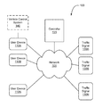
- FIG. 1 is an illustration of a system 100 in accordance with one embodiment of a routing system.
- the system 100 includes a plurality of user devices 110 A-N, that are coupled to a network 101 .
- user devices 110 may include a computer terminal, a personal digital assistant (PDA), a wireless telephone, an on-vehicle computer, or various other user devices capable of connecting to the network 101 .
- the communications network 101 is a local area network (LAN), a wide area network (WAN), a wireless network, an intranet, or the Internet, for example.
- user device 110 is an iPhone® device provided by Apple, Inc. and programmed with a user-downloadable application providing one or more of the functions described herein.
- the system 100 also includes a plurality of traffic signals 130 A-N that are connected to the network 101 and at least one controller 120 .
- the traffic signals 130 A-N are all the traffic signals for all the controlled intersections in a local area.
- the controller 120 controls the operation of all the traffic signals 130 A-N in the system.
- one controller 120 may control a subset of all the traffic signals 130 A-N, and other controllers may control a portion or all of the remaining traffic signals.
- system 100 does not control any traffic lights.
- a user device e.g., 110 A, further interfaces with a vehicle control system 140 , such as via a Bluetooth or wired connection, to control aspects of vehicle operation as described herein.
- FIG. 2 is a block diagram of a user device 110 , in accordance with an embodiment of the invention.
- one user device e.g., 110 A
- another user device e.g., 110 B
- each user device 110 includes a GPS receiver 111 , a user interface 112 , and a controller interaction module 113 .
- the GPS receiver 111 of the user device 110 functions to identify a precise location of the user device 110 from GPS satellite system signals received at the user device 110 . Suitable GPS receivers are commonly found in handheld computing devices such as cell phones, on-board navigation systems, and other electronics. The GPS receiver 111 determines the location of the user device 110 for communication to the controller 120 . Alternatively, cellular signals or other known location-determining technologies may be used to determine the position of the user device 110 . For clarity, the location is discussed herein as having been determined from GPS signals although GPS signals, cellular signals or other technologies can be used in alternate embodiments.
- the user interface 112 of the user device 110 allows the user to input information into the user device 110 and displays information to the user.
- the user may input a desired destination into the user interface 112 of the user device 110 .
- the user interface 112 may display directions or a route to travel to arrive at the desired destination.
- the user interface 112 may also display other information relevant to the driver derived from the GPS signals received by the GPS receiver 111 , received from the controller 120 , or from other sources, such as current rate of speed, upcoming traffic signals, the light status of such traffic signals, and the like.
- the controller interaction module 113 of the user device 110 manages the communication between the user device 110 and the controller 120 . Specifically, the controller interaction module 113 sends the location information determined by the GPS receiver 111 to the controller 120 and receives the controller's messages to the user device 110 regarding traffic, navigation routes, traffic signals, and the like. As detailed below, the functions of controller 120 may in actuality be spread among multiple controller devices, for instance one under the authority of a municipality and another under the authority of a private company.
- FIG. 3 is a block diagram of a traffic signal 130 , in accordance with an embodiment of a routing system.
- the traffic signal 130 includes a signal module 131 and a controller interaction module 134 .
- the signal module 131 processes instructions to turn the traffic signal lights off and on and processes instructions regarding the timing of the light cycles (e.g., from green to red back to green, or in other cases from green to yellow to red and back to green).
- the signal module 131 may be programmed with a set of default rules for timing of the light cycles based on time of day, day of week, etc. In one embodiment, these default rules are subject to be changed based on instructions received from the controller 120 . In other embodiments, the controller 120 instructs the signal module 131 of the traffic signal 130 with respect to every change in status of the light. In yet another embodiment, the controller 120 does not influence the operation of the traffic signal.
- the controller interaction module 134 of the traffic signal 130 manages the communication between the controller 120 and the traffic signal 130 . Specifically, in one embodiment, the controller interaction module 134 receives the instructions from the controller 120 and passes them to the signal module 131 for controlling the status of the light. (In another embodiment, the controller 120 does not send instructions for controlling the status of the light.) In some embodiments, the controller interaction module 134 sends a report to the controller 120 on the updated status of the lights of the traffic signal 130 .
- FIG. 4 is a block diagram of a controller 120 , in accordance with an embodiment of the routing system.
- the controller includes a user device interaction module 123 , a traffic signal interaction module 124 , a traffic module 125 , a routing module 126 , a traffic signal instruction module 127 , an advertisement module 128 and a database 129 .
- the user device interaction module 123 of the controller 120 manages the communication with the user device 110 from the controller's side.
- the user device interaction module 123 receives location information and optionally destination information from the controller interaction modules 113 of the user devices 110 and sends traffic, routing, or traffic signal related information to the user devices 110 via the user device interaction module 123 .
- the traffic signal interaction module 124 of the controller manages the communication with the traffic signal 130 from the controller's side.
- the traffic signal interaction module 124 may send instructions to the traffic signals 130 and may receive status updates regarding the status of the lights of the traffic signals 130 in various embodiments.
- the traffic module 125 receives the location information identifying the location and, in some embodiments speed, of the user devices 110 from the user device interaction modules 123 and stores the information in a database 129 .
- the traffic module 125 may also store information regarding traffic conditions from other sources such as other users with user devices 110 , traffic services, news reports, and the like.
- the traffic module 125 may also receive data regarding events likely to influence traffic such as construction projects, emergency vehicle activity, and the like.
- the traffic module analyzes the received traffic data to determine current and in some embodiments predicted future traffic conditions, and the traffic module 125 may report traffic conditions through the user device interaction module 123 to the user devices 110 .
- the routing module 126 combines the information communicated to the controller 120 about the locations of the user devices 110 and optionally their destinations with the traffic conditions assessed by the traffic module 125 to prepare routing instructions for the user devices 110 .
- the assessment includes observed traffic conditions, predictive analysis, or both.
- the routing module 126 may also consider the status and timing of the traffic signals 130 to recommend routes and speeds that result in less time for drivers spent waiting at red lights or that are otherwise advantageous, as well as to provide predicted speeds for all or part of a recommended route.
- the traffic signal instruction module 127 combines information communicated to the controller 120 about the locations of the user devices 110 and optionally their destinations with the traffic conditions assessed by the traffic module 125 to prepare instructions regarding when to turn lights off and on and the appropriate timing for the cycle of lights.
- the traffic signal instruction module 127 may be programmed with a set of rules regarding constraints. For example, emergency responder vehicles may be given priority to reach their destinations without interruption by stoplights. Further constraints may include a maximum limit to the time length of a light, the maximum number of cars waiting for a light to change, the relative timing or synchronization between lights, and so forth. In one embodiment yet another constraint is presence of one or more other vehicles being routed and tracked by the system 100 . For example, it may be known that a tracked vehicle will trigger a light's proximity sensor and cause it to cycle, because the system 100 is routing the vehicle on a known path and is aware of the vehicle's position.
- the advertisement module 128 is included in certain embodiments to present the user with advertising related to a route request. For example, if routing module 126 has determined a route that passes nearby to an advertiser, advertisement module 128 is configured to present an advertisement, such as a coupon, to the user. In one embodiment, advertisement module 128 is configured to detect a destination request from the user that is related to an advertiser, because the advertiser has specifically requested activation upon that destination request (e.g., entry of a competitor's destination) or because the advertiser has requested activation upon any destination request of a particular type (e.g., electronics store). In still another embodiment, mere proximity of a route to a sponsored location triggers an advertisement. Once it is determined that a requested destination relates to an advertiser by one of these mechanisms, advertisement module 128 generates an appropriate coupon or other advertisement for display on user device 110 .
- advertisement module 128 generates an appropriate coupon or other advertisement for display on user device 110 .
- Advertisement module 128 is configured in certain embodiments to provide information about an advertiser to a user even in circumstances where the advertiser's location and the requested destination are in dissimilar directions. In some instances, the advertiser's location may be in another direction but closer or quicker in driving time than the originally requested destination. In other instances, the information about an advertiser (such as a discount coupon) may provide an incentive for a user to go to that advertiser's location even if it is not closer or quicker.
- the user may still be appropriate to provide the user with a coupon or other information about that advertiser, for instance to ensure that the user actually decides to go to that location or to encourage the user to make additional purchases from the advertiser.
- other relevant information is generated for display on user device 110 .
- other relevant information is generated for display on user device 110 .
- a message warning the user that the store will be closed is displayed on user device 110 and the user is asked to verify whether that destination is still desired.
- an alternate proposed destination i.e., a store that will not be closed is suggested to the user via display on user device 110 as well.
- a single database 129 is shown in FIG. 4 as internal to the controller 120 , however in other embodiments, the database 129 may comprise a plurality of data stores, some or all of which may reside remotely from the controller 120 .
- the data stores may be elsewhere on the network 101 as long as they are in communication with the controller 120 .
- the database 129 is used to store user device locations, traffic conditions, alternative navigation routes and maps, traffic signal information including locations and traffic signal instructions, and any other data used by the controller for purposes such as analysis or communication with user devices 110 or the traffic signals 130 .
- controller 120 In some embodiments, aspects of the operation of controller 120 that deal specifically with warning third parties (i.e., other vehicles and pedestrians) of an impending traffic control violation are handled by a separate warning system controller 120 A.
- Warning system controller 120 A is in such embodiments implemented separately to allow it to be administered by a different authority than the other operations of controller 120 .
- controller 120 (handling the functions of traffic signal interaction module 124 and 127 ) may be administered through a municipality having authority over the intersection, while warning system controller 120 A (handling other functions described above) may be privately administered, e.g., by a company providing mapping, routing, or other information to users.
- controller 120 are, in various embodiments, administered by one or more controllers having access as required to database 129 , not all of which are necessarily under a common authority.
- controllers having access as required to database 129 , not all of which are necessarily under a common authority.
- portions of database 129 and related processing functions may take place in a user device 110 A of a vehicle about to run a red light at an intersection, at a user device 110 B of a pedestrian about to cross the intersection, and at one or more central facilities remote from the intersection.
- quickest warning times will be achieved by taking issues such as processor speed and network delays into account when determining what portion of processing optimally occurs at each location.
- FIG. 5 is high-level block diagram illustrating an example of a computer 500 for use as a user device 110 , a controller 120 or a traffic signal 130 , in accordance with an embodiment of the routing system. Illustrated are at least one processor 502 coupled to a chipset 504 .
- the chipset 504 includes a memory controller hub 550 and an input/output (I/O) controller hub 555 .
- a memory 506 and a graphics adapter 513 are coupled to the memory controller hub 550 , and a display device 518 is coupled to the graphics adapter 513 .
- a storage device 508 , keyboard 510 , pointing device 514 , and network adapter 516 are coupled to the I/O controller hub 555 .
- Other embodiments of the computer 500 have different architectures.
- the memory 506 is directly coupled to the processor 502 in some embodiments.
- the storage device 508 is a computer-readable storage medium such as a hard drive, compact disk read-only memory (CD-ROM), DVD, or a solid-state memory device.
- the memory 506 holds instructions and data used by the processor 502 .
- the pointing device 514 is a mouse, track ball, or other type of pointing device, and in some embodiments is used in combination with the keyboard 510 to input data into the computer system 500 .
- the graphics adapter 513 displays images and other information on the display device 518 . In some embodiments, the display device 518 includes a touch screen capability for receiving user input and selections.
- the network adapter 516 couples the computer system 500 to the network 101 . Some embodiments of the computer 500 have different and/or other components than those shown in FIG. 5 .
- the computer 500 is adapted to execute computer program modules for providing functionality described herein.
- module refers to computer program instructions and other logic used to provide the specified functionality.
- a module can be implemented in hardware, firmware, and/or software.
- program modules formed of executable computer program instructions are stored on the storage device 508 , loaded into the memory 506 , and executed by the processor 502 .
- the types of computers 500 used by the entities of FIG. 1 can vary depending upon the embodiment and the processing power used by the entity.
- a user device 110 that is a PDA typically has limited processing power, a small display 518 , and might lack a pointing device 514 .
- the controller 120 may comprise multiple blade servers working together to provide the functionality described herein.
- the portion of data storage and processing performed by each device is preferably based in part on the processing power and available communication bandwidth for each such device.
- FIG. 6 is a flow chart illustrating a method of providing improved traffic routing.
- the current locations (and in some embodiments, speeds) are received from a plurality of user devices 110 in vehicles.
- the current locations may be ascertained using GPS or other signals by the user devices 110 and communicated to the controller 120 via the network 101 , for example.
- the destinations of the users are also communicated from the user devices 110 to the controller 120 .
- the traffic conditions are determined responsive to the received locations of the user devices 110 .
- the traffic conditions are also determined responsive to other sources of traffic information such as traffic websites, traffic services, etc.
- roadwork and emergency vehicle activity are also considered in determining the traffic conditions.
- system 100 provides predictive modeling of anticipated traffic speeds based on the various sources of information provided to system 100 .
- traffic signals are controlled responsive to the determined traffic conditions. For example, instructions are sent from controller 120 to individual traffic signals 130 to turn them on or off or adjust the timing of the light cycles to ease congestion identified in the traffic conditions.
- step 607 vehicles are routed according to the controlled traffic signals and other traffic information.
- the controller 120 may send route information or speed information to the user devices 110 to enable the drivers of the vehicles in which the user devices 110 reside to avoid red lights and/or avoid congested areas if the instructions from the controller 120 with respect to the route information or speed information are obeyed.
- Embodiments that provide systems, methods, and computer-readable storage media that use location-based technologies such as GPS to provide improved traffic routing have been described above. Benefits of these embodiments include:
- a location-aware user device 130 such as a smart phone in a vehicle sends a message via the Internet to traffic signal 130 indicating that the vehicle is approaching the traffic signal 130 from a particular direction and may also transmit the vehicle's destination. If appropriate, traffic system 130 changes its operation so as to allow the vehicle to pass with minimal slowdown.
- a smart phone such as the iPhone® device provided by Apple, Inc. and mentioned above.
- Such device is location-aware and is readily programmed by software applications to perform a variety of functions.
- a software application directs the device to periodically send its location and optionally the vehicle's destination to a specified site via the Internet, for example controller 120 .
- controller 120 then sends traffic signal 130 a signal indicating that traffic is approaching from a particular direction. If appropriate (for instance during late-night hours with little expected traffic), traffic signal 130 then changes the state of its lights so as to allow the vehicle to pass without having to stop.
- controller 120 can compare the number of eastbound/westbound vehicles at a particular intersection with the number of northbound/southbound vehicles and cause traffic signal 130 to adjust its light cycles accordingly.
- One-way communications in the other direction may also be effective.
- a software application on user device 110 may obtain from the traffic signal 130 , via controller 120 , an indication that a light has just turned red and will not turn green again for one minute. If the intersection is not visible to the driver, for instance because the approach is hilly or on a curve, this information can be used to tell the driver that there is no point in approaching the intersection quickly, since the vehicle will only need to wait for the green light anyway. Thus, safety can be enhanced near “blind” or otherwise dangerous intersections.
- knowledge of the cycle of a traffic signal from a distance can help drivers time their approaches to controlled intersections to coincide with a green light. Thus, drivers can reduce the time they spend waiting at red lights.
- users are provided incentives to keep their devices in active operation while enroute, rather than just at the outset of a journey. This is advantageous to all users of the system because the more users who are “live” on the system (e.g., have the appropriate application operating on their user devices 110 ), the more information can be collected from such users regarding traffic information at various locations.
- the more users who are “live” on the system e.g., have the appropriate application operating on their user devices 110
- the more information can be collected from such users regarding traffic information at various locations.
- an “app” implementing the system is kept on during transit, not only will the user obtain updated information, but the system will obtain ongoing information from that user, such as traffic speed at the user's location.
- a user interface of the application running on user devices 110 provides updated information during travel.
- the predicted state of a light that the user is approaching is presented to the user differently depending on the certainty of the prediction.
- a visual display of the light's predicted state can start out, when the prediction is relatively uncertain, as a rather faded color, and increase in intensity as the certainty grows.
- a change in a light's predicted state can be announced to the user by audio as well as visual messaging, and the proposed route can likewise be altered on the fly if an originally preferred route now appears suboptimal due to changes in the predicted state of one or more lights.
- multiple types of displays are presented to users indicating information regarding a light's predicted state, such as minimum speed to reach the intersection while the light is still green, maximum speed to reach the intersection above which increased speed would only result in waiting for the light to turn green, colored indicators showing predicted state of the light that do not suggest a speed but are based on not exceeding the speed limit, and simple “SPEED UP” or “SLOW DOWN” messages for a current route.
- data regarding a user's actual speed is collected from user devices 110 over time and used to determine which information display leads to the safest behavior (greatest conformance to speed limit least running of red lights, etc.).
- this is done by a machine learning module (not shown) implemented, for example, by controller 120 If it is found that one type of indicator results in safer driving then that display is used. Over time, it may be that for one driver a first type of display results in safer driving while for another driver a second type of display results in safer driving. In such case, the display is individualized for each driver accordingly.
- machine learning for system 100 is implemented by providing different drivers with different types of displays, and then determining after a period of time which of the displays results in the safest driving averaged over all users.
- different displays are presented to a driver at different times, and the safest design for each driver eventually becomes the one that is presented most often or, in some embodiments, the only one that is displayed.
- system 100 is configured in one environment to sometimes provide only a first display to a user device 110 and other times only provide a second display to the user device 110 .
- user device 110 is instructed to provide a first display initially followed by a second display, such as a green dot followed by a proposed speed.
- a second display such as a green dot followed by a proposed speed.
- inferences are made as to whether a driver began to exceed the speed limit only after the second display appeared.
- the order in which the displays are updated is in some embodiments switched while in a learning phase to allow for more complete testing of which displays lead to safer driving.
- traffic data collected from user devices 110 over a period of time is stored in database 129 and processed further by controller 120 to determine or refine routes proposed by routing module 126 .
- vehicle speed information collected over a period of time is used to determine the presence of stop signs that were not previously known by the system. Knowledge of where such stop signs are located allows the system to build in appropriate delays when considering routes that include intersections with those stop signs. Similarly, over a long period of time it may be evident that no user devices 110 have traversed a given portion of a mapped road. Such data may indicate that the road was planned but never built, that the road has been closed, or that the road is unavailable for use for some other reason.
- routing module 126 Based on such collected data, in some routing module 126 ignores such road segments as being available for a proposed route. Conversely, location and speed data from user devices 110 may indicate that a new road has been built that is not on the base map loaded into database 129 , and if there is enough vehicular use of such a route, then routing module 126 assumes such a path, even though not mapped, is available for a proposed route.
- system 120 Still more detailed collected and real-time information from user devices 110 is used by system 120 in certain embodiments.
- Real-time average vehicle speed from other vehicles, historical average vehicle speed, vehicle speed variance over time, deviation of a given user's vehicle speed compared to other vehicles' speeds over the same route (indicating an aggressive or conservative driving manner) and best/worst case speed data are all used as inputs by system 120 to predict the time it will take a vehicle corresponding to a particular user device 110 to traverse a specific segment of a possible path.
- system 100 may determine that a particular segment of road is subject to 25 mph speed limits during certain times and 40 mph speed limits during other times, for instance indicating a school zone with a reduced speed limit sign that flashes to invoke the lower limit during times when children are present. Further, system 100 determines that some users tend to be conservative and drive according to the 25 mph sign regardless of whether the lights are flashing, while others reduce speed only when the lights are flashing. For users who reduce speed all of the time, system 100 routes them based on a lower expected speed regardless of the actual speed limit; other users get routed based on an expectation that they will match the actual speed limit in effect at the time. Changes in speed limit also occur on some roadways based on time of day, vehicle type (truck or automobile), construction activity and the like. In some embodiments system 100 detects patterns in collected data indicating such changes and accounts for them in determining routes and estimating transit times.
- system 100 adaptively segments routes into smaller pieces over time when collected data suggest such smaller segmentation will yield more accurate estimates of travel time. For example, system 100 may start out by considering the entirety of a street as one segment, but data collected over time may indicate that there is a school zone impacting a certain portion of the road. In response, system 100 divides the road into three segments, so that those who exit the road well before the school zone are not considered subject to the reduced speed limit that would affect a driver going past the school.
- school bus routes often slow traffic considerably, but only for a small portion of each day.
- system 100 may infer that during school days, certain routes that otherwise have a much higher average speed will be congested at specific known times. During those times, preference is given to routes that avoid approaching or following a school bus. Not only does such routing improve transit times, but it also increases safety by reducing the number of conflict points between vehicles and children getting on or off a bus.
- a particular advantage of using data collected from user devices 110 for this purpose is that temporal changes in estimated segment transit times and correlations do not need to be calculated for all road segments, but only those showing significant time-dependent variations. Processing requirements for system 100 are thus dramatically reduced compared with a system configured to make temporal predictions for all road segments.
- external data sources are used instead of, or in addition to, the collected data referenced above.
- significant periodic changes in observed traffic at a particular location trigger system 100 to search external data sources (such as through a location-based internet search) to determine a cause of such changes, such as presence of a school, church, railroad crossing or sports venue; notice of a period of road construction; or public warning that a road is only seasonal and is not maintained in winter.
- system 100 is programmed to then search for information that correlates with the observed data and can be used to make predictions for transit time in the future.
- system 100 determines, by a location-based search, that a school is located where there are large variations in transit time, system 100 then searches the Internet for a school calendar and extracts information as to what days the school is open so that the system can predict when traffic is likely to be slowed down in the vicinity of the school.
- a map database may not include an indication that the school referenced above is at a certain location, but after presence of the school is inferred based on observed data, that information is usable for purposes such as vehicle routing.
- an application providing driving directions makes use of the data to augment the manner in which information is presented to a driver, so that instead of stating “make a right on Oak Street” more helpful directions can be given, such as “make a right after passing the school, onto Oak Street”.
- 13/425,707 features such as traffic lights and stop signs can be detected by such observations, so augmented GPS directions such as “turn right at the light onto Main Street” are provided in one embodiment, even when a primary map database does not indicate that there is a traffic light at that intersection. Further such augmentation is available in some embodiments using location-based advertisements, as an additional benefit to advertisers.
- a location-based advertiser will typically provide a location for its business, which can then be used as described above to augment GPS directions (e.g., “Turn right just after the Starbucks onto Elm Street”).
- the user interface 112 of user device 112 from FIG. 2 is implemented via a display system that includes a destination display 710 shown in FIG. 7 , a routing display 810 shown in FIG. 8 , and a settings display 910 shown in FIG. 9 .
- destination display 710 is configured to be a starting place for a driver's use of the system.
- a search bar 711 allows a user to enter a new destination by entering text to represent a street address, intersection, or business name; alternatively the system allows a user to select a destination from a list of previous destinations 712 .
- the system will be in a “cruising” mode in which it is assumed that the driver will remain traveling as straight as possible; once the driver turns, the system again assumes that the driver will travel as straight as possible.
- Routing display 810 is configurable to show a user's current position, starting location and ending location, as well as speed, traffic light and route information.
- a speed limit indicator 811 shows the speed limit at the driver's current location, based on known data as discussed above. This indicator normally has a white background, but in one embodiment gradually turns to red as the driver's speed exceeds the legal limit.
- a traffic light indicator icon 812 and an information bar 813 are also provided.
- Indicator icon 812 is intended to be large enough for a driver to easily see at a quick glance, and is color-coded to show the state of an upcoming traffic light.
- the color coding relates to the current state of the light; in another embodiment the color coding relates to the system's prediction as to whether an upcoming traffic light will be red or green upon the user's arrival. In one embodiment, predictions of the state of an upcoming light may be more or less certain, as discussed above, and the icon will be colored more intensely to show a strong prediction and in a more faded manner to show a weak prediction.
- Information bar 813 is also color coded, with a background color indicating both a predicted state of the light and confidence in that prediction at the time the user is expected to arrive. The user's actual speed is shown by a surrounding box and a range of speeds surrounding the current speed limit is also displayed.
- the ETA in this instance indicates that the user would arrive at the light in seven seconds if traveling at 20 mph, as opposed to six seconds at the driver's current rate of 26 mph.
- the name of the upcoming intersection is also provided at the bottom of bar 813 .
- Drivers can use bar 813 to determine, for example, whether to slow down because the light will be red at the time of arrival regardless of the current speed.
- Display 810 also shows the states of other nearby traffic lights (e.g., 816 ), the driver's current location 815 , and the selected route 814 .
- the duration of the route is also shown 817 , as well as the destination 818 .
- user tracking button 819 allows the user to once again display current location 815 .
- routing display 810 includes an indicator that displays the time remaining before an upcoming light changes state. If the upcoming light is changing to red and there is time to spare, the driver would, among other things, be able to save fuel by driving only as fast as necessary to pass the light in time. If the timer indicates that the driver will not reach the green light, the driver may slow down to save fuel since he will be stopping at the red light regardless of the speed he travels. A timer that shows how long until a light turns green can also provide impetus for a driver to slow down. A driver may be inclined to slow down and save fuel if he knows that he will still arrive at the next light by the time it turns green.
- system 100 is also capable of determining and storing how certain indicators affect the behavior of drivers. In one embodiment this data is used to determine whether the indicator should be displayed to the driver in the future. If an indicator promotes unsafe behavior, it may no longer be shown to the driver. On the other hand, if an indicator causes a driver to adhere to the speed limit, it will continue to be shown. For example, if displaying the time remaining before a light turns red causes the driver to go as fast as is necessary to reach the light in time, the indicator may no longer be shown. Similarly, if the information bar 813 indicates that the traffic light will be green when the driver reaches it if the driver exceeds the speed limit, the driver may choose to travel faster than the speed limit.
- the system can choose to not display certain indicators that are found to promote unsafe driving. Rules determining which indicators should be displayed can be applied to multiple drivers or to specific drivers based on their actions. In some embodiments, the user may be given a choice of whether indicators promoting unsafe behavior such as speeding should be displayed or suppressed.
- routing display 810 also includes location-based advertisements 820 , such as a coupon and prominent arrow showing the location of an advertiser. Selection of an advertisement 820 is, in various embodiments, dependent upon context.
- an advertisement is selected for display based on the destination that the user has selected. In the example shown in FIG. 8 , a coupon for an electronics store is displayed. This may be in response to the user entering a destination location that is a competing electronics store, for instance.
- location-based advertisements are selected based on the projected path of the user. In other embodiments, location-based advertisements are selected based on keywords used while in the destination display 710 , recent web searches, user profile information and other characteristics that can be gleaned from historical use of user device 110 .
- advertisements based only on proximity of the user's location, or a proposed route, to a sponsored business are displayed on user device 110 .
- a user seeking an electronics store may be provided with an advertisement for a coffee shop not far from the proposed route to the electronics store.
- other information relating to destinations is provided as well. As one example, if a destination is an electronics store and that store will be closed at the expected arrival time of the user, a warning message to that effect is displayed on the user device 110 . Likewise, if the user has input a parking facility as a destination and that facility is full, such information is provided on the user device 110 .
- alternate destinations are suggested via display on user device 110 (e.g., a store that will still be open or a parking facility that is not full). Display of such suggested destinations is in some embodiments influenced by sponsorship such that certain alternate destinations are favored over others based on such destinations paying for that benefit.
- a settings display 910 provides user selection of various display-related features.
- a map rotation control 911 determines whether the displayed map is oriented to the direction of travel or in a conventional “North-up” mode.
- a “Predictions HUD” control 912 determines whether the traffic light indicator 812 and color bar 813 are displayed to the user.
- “Lights on map” control 913 is used to enable or disable display of traffic lights, e.g., 816 .
- settings display 819 provides controls that determine the behavior of routing system 100 .
- “Lights” control 914 is used to determine whether delays due to traffic lights will be considered in estimating transit times.
- “Stops” control 915 likewise relates to whether delays for stop signs will be considered.
- “Turns” control 916 similarly enables or disables delay calculations for time spent making right or left turns.
- user devices 110 are in one embodiment also configured to provide a warning when a vehicle is about to pass a traffic control illegally, for instance by going through an intersection when a traffic light is red.
- FIG. 10 is a flow chart illustrating a method of providing such a warning.
- step 1001 the current location and speed of a vehicle is determined and communicated to controller 120 as described above.
- a correspondence is generated (i.e., determined) with an upcoming traffic control, e.g., traffic signal 130 A.
- routing information already provided by the driver is used to predict the next traffic control that the vehicle is expected to encounter; in another embodiment a simple geographical search is made for the next traffic control likely to be encountered based on the vehicle's current location and direction of travel.
- a subsystem of controller 120 e.g., routing module 126 , is programmed to generate the correspondence.
- information regarding the location and speed of the vehicle is used to estimate its time of arrival at the traffic control, and information regarding the current and historical states of the traffic control (for example, how long a traffic signal's light stays yellow before turning red) is used to predict the likely state of the traffic control at the time of arrival.
- this information is updated from time to time.
- the update is accomplished at regular intervals (e.g., every three seconds).
- the update is accomplished based on changes in state (e.g., change of the state of the traffic signal, change in the speed of the vehicle).
- the update is accomplished based on a factors, such as distance from the vehicle to an intersection (more updates as the vehicle gets closer).
- combinations of such updating factors are used to balance processor and communications bandwidth loading against accuracy of prediction.
- the estimated time of arrival is generated by routing module 126 , and the likely state of the traffic signal at that time is generated by traffic signal interaction module 124 .
- controller 120 (or warning system controller 120 A in embodiments using such a separate controller) sends a warning signal or activates countermeasures as detailed below 110 if the vehicle is getting sufficiently close to a traffic control (e.g., traffic signal 130 ) without slowing down (i.e., without indicating that the driver is preparing to stop) such that it seems likely that the vehicle will enter the intersection at a time when the traffic signal 130 will already have turned red.
- a traffic control e.g., traffic signal 130
- speed control e.g., traffic signal 130
- slowing down i.e., without indicating that the driver is preparing to stop
- the vehicle's braking system are used in certain embodiments to predict whether the driver of the vehicle is planning to stop at the intersection or proceed through it.
- the warning is progressive, such as with short, low volume beeps at first transitioning to a loud continuous alarm tone as the vehicle approaches the intersection and the prediction of running a red light becomes more certain.
- audible warnings e.g., tones, voice
- visual warnings e.g., on a display 112 of user device 110 , on a dashboard indicator light, on a heads up windshield display
- warnings begin at approximately 500 meters from an intersection when the vehicle is traveling at high speed or on a divided highway but at only 100 meters from an intersection when the vehicle is traveling at lower speed or on a small two-lane road.
- Other adjustments in the distance at which a warning is triggered include, in various embodiments, factors such as applicable speed limits, presence of blind curves in front of a traffic control, whether it is day or night, whether it is rush hour, and weather conditions.
- operational parameters such as type of notification and operational distance are user-selectable based on personal preference.
- the warnings are generated by user device interaction module 123 .
- network communications latencies may be significant (e.g., 3 G communications from a vehicle to the controller over the Internet and 3 G communications from the controller to another user device over the Internet)
- such operational parameters include consideration of communications delay time.
- the warnings are generated not only to a driver's own user device 110 A, but additionally or alternatively to user devices 110 other than in the vehicle about to enter the intersection in violation of the traffic control.
- a warning that a vehicle with user device 110 A is about to illegally enter an intersection is generated and issued via the Internet to other user devices within a certain geographical range of user device 110 A (e.g., 500 meters).
- a second vehicle with user device 110 B receives a warning putting its driver on alert for a potential red light runner.
- it is a pedestrian, rather than a driver, who is equipped with the second user device 110 B, and is alerted to the potential impending danger.
- a pedestrian's user device 110 B is configured in one such embodiment to make a loud “honk” sound as the warning.
- the warning is issued via the Internet directly to traffic signal 130 N, which is configured in various embodiments to react to the warning in multiple manners.
- the traffic signal 130 N sounds a loud alarm at the intersection; in another it turns all signals to red until the violating vehicle has either stopped or passed; in still another it activates all strobe lights at the intersection (e.g., those used for emergency vehicle passage and those used for illumination of traffic enforcement cameras).
- data are provided to local processors, e.g., user devices 110 A, 110 B and processing is accomplished locally on those machines to determine whether a warning should be issued.
- the general allocation of processing and communications is, for example, as follows. First, user device 110 A inside a vehicle sends a message to controller 120 with its location, with new location messages being sent from time to time. Controller 120 processes this information and determines that the vehicle may be approaching a traffic light, and thus sends to the vehicle (via the Internet to user device 110 A) the location of the traffic light and its status (e.g., light is now green but is expected to turn red in 5.2 seconds).
- the light status information is also refreshed periodically, for instance when the light turns to amber and then again when it turns to red.
- controller 120 be aware of another user device 110 B, in this example carried by a pedestrian, in the vicinity of the intersection, it also sends to that device the information about user device 110 A and the traffic light.
- User devices 110 A and 110 B then independently process this data as described above to determine whether a warning is needed based on currently available information. If so, those devices implement the warning directly, without need for further communication (with associated latency).
- controller 120 may be configured to perform the processing described above instead.
- known adaptive distributed processing techniques can be applied to tune such allocation over time to minimize the time needed to generate the warning.
- vehicular controls are also applied based on prediction that a vehicle will be entering an intersection illegally.
- user device 110 A interacts with the vehicle's control system 140 (either by an existing general purpose connection such as Bluetooth or by direct wired connection) and deactivates the cruise control as an early indication to the driver that slowing down will be necessary.
- the ABS system is activated to provide sensory indication through two or three quick automated brake “pumps” that slowing will be required. In a slightly more aggressive implementation, more significant automatic application of the brakes is made.
- the user device interacts with the vehicle control system 140 to flash the vehicle's lights and sound the horn as a further warning.
- vehicle control system 140 Some automobiles are equipped with cruise control features and braking systems that automatically become prepared to stop a car quickly when danger is detected (known variously as “active cruise control”, braking assist or “adaptive brake assistant”) and in such automobiles, the signal from user device 110 A activates these systems before any on-board sensors (e.g., radar, lidar, sonar proximity systems) may recognize the need to do so.
- on-board sensors e.g., radar, lidar, sonar proximity systems
- historical data regarding particular user devices 110 and how often they are associated with certain driver behaviors can also be used to predict whether a vehicle is likely to run a red light. For instance, for user devices that are often involved in running red lights (as opposed to merely heavy braking and acceleration at controlled intersections, but no red light running), such instances are recorded and logged so that not merely the speed of a vehicle approaching an intersection, but the past history of associated user devices, factors into determination of when to issue, and when to escalate, the warnings described herein. In some embodiments, such information regarding driver aggressiveness is stored in the database 129 of controller 120 .
- driver-specific tuning of thresholds can be used not only for the vehicle about to enter an intersection illegally, but also for other nearby vehicles as well.
- vehicle controls can be activated (or deactivated, as appropriate) based on such external situations that are detected as described herein.
- some vehicles have a special mode of operation when dangerous conditions are sensed (e.g., brake assist as mentioned above) and external detection of deteriorating weather conditions via information received from user device 110 A in one embodiment causes such a mode of operation to be activated.
- Certain aspects of the present invention include process steps and instructions described herein in the form of an algorithm. It should be noted that various of the process steps and instructions disclosed herein could be embodied in software, firmware or hardware, and when embodied in software, could be downloaded to reside on and be operated from different platforms used by real time network operating systems.
- the present invention also relates to an apparatus for performing the operations herein.
- This apparatus may be specially constructed for the required purposes, or it may comprise a general-purpose computer selectively activated or reconfigured by a computer program stored on a computer readable medium that can be accessed by the computer and run by a computer processor.
- a computer program may be stored in a computer readable storage medium, such as, but is not limited to, any type of disk including floppy disks, optical disks, CD-ROMs, magnetic-optical disks, read-only memories (ROMs), random access memories (RAMs), EPROMs, EEPROMs, magnetic or optical cards, application specific integrated circuits (ASICs), or any type of media suitable for storing electronic instructions, and each coupled to a computer system bus.
- the computers referred to in the specification may include a single processor or may be architectures employing multiple processor designs for increased computing capability.
- the present invention is well suited to a wide variety of computer network systems over numerous topologies.
- the configuration and management of large networks comprise storage devices and computers that are communicatively coupled to dissimilar computers and storage devices over a network, such as the Internet.
Abstract
Description
- 1. Better synchronization of drivers and traffic lights. As a result, people can spend less time waiting at traffic lights. Additionally, better synchronization results in drivers being able to maintain a more constant speed and avoid abrupt accelerations and decelerations caused by stopping at traffic lights. Reduced acceleration/deceleration while driving results in increased miles per gallon of gas for cars and reduced carbon emissions. The better synchronization of drivers and traffic lights results in tangible benefits to everyone, including drivers who do not use the
user devices 110, because embodiments of the invention avoid gridlock and generally improve the flow of traffic. Thus, helping a relative handful of drivers who use theuser devices 110 to proceed smoothly will also help alleviate the burdens of traffic to the rest of the drivers. - 2. Improved ability to clear roads for emergency responders. Not only can traffic lights be informed of an emergency response vehicle approaching in order to block cross traffic to avoid an accident, but also can turn appropriate lights green to relieve congestion in the path of an emergency response vehicle. Non-emergency traffic, meanwhile, is routed elsewhere so that by the time an emergency vehicle arrives at an intersection, there are fewer other vehicles in contention with it.
- 3. Improved ability to support mass transit. The traffic lights can be preferentially managed to support buses, trolleys, and trains to avoid having these mass transit vehicles wait for traffic lights. In addition, cars can be managed to avoid having to wait for trains or other mass transit vehicles.
- 4. Load balancing during busy periods. The traffic lights and signals to drivers can be managed so as to balance the traffic between a number of known traffic bottlenecks or popular routes (such as multiple bridges across a single river, and main thoroughfares into or out of an urban area).
- 5. Synchronization of drivers with each other. In one particular embodiment, drivers are directed among a plurality of routes according to characteristics of the vehicle, the driver, or the desired destination. For example, all trucks are directed to one thoroughfare and all cars are directed to another. This helps avoid the inconveniences to car and truck drivers of travelling on the same route. Namely, trucks reduce the visibility that smaller cars have of the road and trucks' longer acceleration times can frustrate car drivers. The shorter braking distance of cars compared to trucks increases the risk of collisions when both are travelling the same route. Also, truck drivers prefer to travel near other trucks to save on fuel by drafting off of each other. As another example, everyone on route A plans to exit in no less than 5 miles, whereas everyone on route B plans to exit in less than 5 miles. This may improve traffic flow through congested areas.
- 6. Prediction and avoidance of congestion. Drivers can be routed around congested areas, thus easing congestion. This results in less driving time and lower carbon emissions.
- 7. Improved traffic monitoring. The results of accurate traffic monitoring can be used in many applications, such as to plan new roads and improvements to infrastructure, or to coordinate the timing of construction projects on infrastructure to lessen the impact on drivers.
- 8. Accurate real-time traffic information, including on city streets. Accurate traffic information is useful for trip planning and commuting. The real-time traffic conditions could be used as inputs into various other scheduling systems to ensure timely arrivals for meetings, events, etc. For example, based on the traffic conditions for any given day, an alarm clock may be programmed to wake a person up 30 minutes before he needs to leave for work in order to arrive on time.
Claims (2)
Priority Applications (6)
| Application Number | Priority Date | Filing Date | Title |
|---|---|---|---|
| US13/542,938 US10083607B2 (en) | 2007-09-07 | 2012-07-06 | Driver safety enhancement using intelligent traffic signals and GPS |
| US13/747,145 US20130131980A1 (en) | 2007-09-07 | 2013-01-22 | Resolving gps ambiguity in electronic maps |
| US13/775,649 US20130166109A1 (en) | 2007-09-07 | 2013-02-25 | Driver Red Light Duration Notification System |
| US15/076,116 US9852624B2 (en) | 2007-09-07 | 2016-03-21 | Network security system with application for driver safety system |
| US15/804,630 US10198942B2 (en) | 2009-08-11 | 2017-11-06 | Traffic routing display system with multiple signal lookahead |
| US15/822,715 US10311724B2 (en) | 2007-09-07 | 2017-11-27 | Network security system with application for driver safety system |
Applications Claiming Priority (8)
| Application Number | Priority Date | Filing Date | Title |
|---|---|---|---|
| US11/851,953 US9043138B2 (en) | 2007-09-07 | 2007-09-07 | System and method for automated updating of map information |
| US23312309P | 2009-08-11 | 2009-08-11 | |
| US12/639,770 US20110037619A1 (en) | 2009-08-11 | 2009-12-16 | Traffic Routing Using Intelligent Traffic Signals, GPS and Mobile Data Devices |
| US12/821,349 US20110040621A1 (en) | 2009-08-11 | 2010-06-23 | Traffic Routing Display System |
| US12/886,100 US20110037618A1 (en) | 2009-08-11 | 2010-09-20 | Driver Safety System Using Machine Learning |
| US13/352,013 US20120139754A1 (en) | 2009-08-11 | 2012-01-17 | Driver Safety Enhancement Using Intelligent Traffic Signals and GPS |
| US13/425,707 US20120179358A1 (en) | 2007-09-07 | 2012-03-21 | System and method for automated updating of map information |
| US13/542,938 US10083607B2 (en) | 2007-09-07 | 2012-07-06 | Driver safety enhancement using intelligent traffic signals and GPS |
Related Parent Applications (2)
| Application Number | Title | Priority Date | Filing Date |
|---|---|---|---|
| US13/352,013 Continuation-In-Part US20120139754A1 (en) | 2007-09-07 | 2012-01-17 | Driver Safety Enhancement Using Intelligent Traffic Signals and GPS |
| US13/425,707 Continuation-In-Part US20120179358A1 (en) | 2007-09-07 | 2012-03-21 | System and method for automated updating of map information |
Related Child Applications (4)
| Application Number | Title | Priority Date | Filing Date |
|---|---|---|---|
| US11/851,953 Continuation-In-Part US9043138B2 (en) | 2007-09-07 | 2007-09-07 | System and method for automated updating of map information |
| US12/821,349 Continuation-In-Part US20110040621A1 (en) | 2007-09-07 | 2010-06-23 | Traffic Routing Display System |
| US13/775,649 Continuation-In-Part US20130166109A1 (en) | 2007-09-07 | 2013-02-25 | Driver Red Light Duration Notification System |
| US15/076,116 Continuation-In-Part US9852624B2 (en) | 2007-09-07 | 2016-03-21 | Network security system with application for driver safety system |
Publications (2)
| Publication Number | Publication Date |
|---|---|
| US20120274481A1 US20120274481A1 (en) | 2012-11-01 |
| US10083607B2 true US10083607B2 (en) | 2018-09-25 |
Family
ID=47067461
Family Applications (1)
| Application Number | Title | Priority Date | Filing Date |
|---|---|---|---|
| US13/542,938 Active - Reinstated 2029-05-09 US10083607B2 (en) | 2007-09-07 | 2012-07-06 | Driver safety enhancement using intelligent traffic signals and GPS |
Country Status (1)
| Country | Link |
|---|---|
| US (1) | US10083607B2 (en) |
Cited By (12)
| Publication number | Priority date | Publication date | Assignee | Title |
|---|---|---|---|---|
| CN110555616A (en) * | 2019-09-05 | 2019-12-10 | 中国气象局广州热带海洋气象研究所 | Dense observation data optimization scheduling method of numerical weather mode assimilation system |
| US10636298B2 (en) * | 2017-08-11 | 2020-04-28 | Cubic Corporation | Adaptive traffic control using object tracking and identity details |
| CN111583680A (en) * | 2020-03-25 | 2020-08-25 | 北京大学 | Emergency traffic auxiliary dispersion method and system |
| US10807610B1 (en) * | 2019-07-23 | 2020-10-20 | Alps Alpine Co., Ltd. | In-vehicle systems and methods for intersection guidance |
| US10948924B2 (en) | 2015-02-06 | 2021-03-16 | Aptiv Technologies Limited | Method and apparatus for controlling an autonomous vehicle |
| US10957192B2 (en) | 2019-08-09 | 2021-03-23 | Ford Global Technologies, L.L.C | Systems and methods for displaying visual content in an automobile stopped at a traffic light |
| US10991247B2 (en) * | 2015-02-06 | 2021-04-27 | Aptiv Technologies Limited | Method of automatically controlling an autonomous vehicle based on electronic messages from roadside infrastructure or other vehicles |
| US11217094B2 (en) | 2019-06-25 | 2022-01-04 | Board Of Regents, The University Of Texas System | Collaborative distributed agent-based traffic light system and method of use |
| US11282384B2 (en) | 2019-11-29 | 2022-03-22 | Brennan James McClay | Traffic light camera and speed camera notification system and method |
| US11597404B2 (en) | 2020-09-23 | 2023-03-07 | Robert D. Fish | Traffic signal alarm device |
| US11840175B2 (en) | 2020-09-23 | 2023-12-12 | Robert D. Fish | Traffic signal alarm device having no navigational control |
| US11935417B2 (en) | 2021-04-13 | 2024-03-19 | Toyota Motor Engineering & Manufacturing North America, Inc. | Systems and methods for cooperatively managing mixed traffic at an intersection |
Families Citing this family (63)
| Publication number | Priority date | Publication date | Assignee | Title |
|---|---|---|---|---|
| US9043138B2 (en) | 2007-09-07 | 2015-05-26 | Green Driver, Inc. | System and method for automated updating of map information |
| US10083607B2 (en) | 2007-09-07 | 2018-09-25 | Green Driver, Inc. | Driver safety enhancement using intelligent traffic signals and GPS |
| US9852624B2 (en) | 2007-09-07 | 2017-12-26 | Connected Signals, Inc. | Network security system with application for driver safety system |
| US10198942B2 (en) | 2009-08-11 | 2019-02-05 | Connected Signals, Inc. | Traffic routing display system with multiple signal lookahead |
| CA2819125A1 (en) * | 2010-12-06 | 2012-06-14 | Thomas W. Cunningham | Traffic signals and related methods |
| US9373207B2 (en) * | 2012-03-14 | 2016-06-21 | Autoconnect Holdings Llc | Central network for the automated control of vehicular traffic |
| US9218698B2 (en) | 2012-03-14 | 2015-12-22 | Autoconnect Holdings Llc | Vehicle damage detection and indication |
| US9253753B2 (en) * | 2012-04-24 | 2016-02-02 | Zetta Research And Development Llc-Forc Series | Vehicle-to-vehicle safety transceiver using time slots |
| JP6082638B2 (en) * | 2013-03-29 | 2017-02-15 | 日立オートモティブシステムズ株式会社 | Travel control device and travel control system |
| US9047766B2 (en) | 2013-04-09 | 2015-06-02 | Here Global B.V. | Method and apparatus for notifying drivers of space required for other vehicles |
| US20140307087A1 (en) * | 2013-04-10 | 2014-10-16 | Xerox Corporation | Methods and systems for preventing traffic accidents |
| US10008113B2 (en) | 2013-04-12 | 2018-06-26 | Traffic Technology Services, Inc. | Hybrid distributed prediction of traffic signal state changes |
| US9928738B2 (en) * | 2013-04-12 | 2018-03-27 | Traffic Technology Services, Inc. | Red light warning system based on predictive traffic signal state data |
| US9396657B1 (en) | 2013-04-12 | 2016-07-19 | Traffic Technology Solutions, LLC | Prediction of traffic signal state changes |
| US20150070195A1 (en) * | 2013-09-11 | 2015-03-12 | Ford Global Technologies, Llc | Method and system to reduce braking for stop lights |
| US9881220B2 (en) * | 2013-10-25 | 2018-01-30 | Magna Electronics Inc. | Vehicle vision system utilizing communication system |
| EP3114574A4 (en) * | 2014-03-03 | 2018-03-07 | Inrix, Inc. | Traffic obstruction detection |
| US9293041B2 (en) * | 2014-04-02 | 2016-03-22 | International Business Machines Corporation | Traffic monitoring via telecommunication data |
| US9972200B2 (en) * | 2014-06-17 | 2018-05-15 | King Abdullah University Of Science And Technology | System and method for traffic signal timing estimation |
| US20160055744A1 (en) * | 2014-08-19 | 2016-02-25 | Qualcomm Incorporated | Systems and methods for traffic efficiency and flow control |
| US9618344B2 (en) * | 2014-12-09 | 2017-04-11 | Brett Harrison | Digital map tracking apparatus and methods |
| US9610893B2 (en) | 2015-03-18 | 2017-04-04 | Car1St Technologies, Llc | Methods and systems for providing alerts to a driver of a vehicle via condition detection and wireless communications |
| US10328855B2 (en) | 2015-03-18 | 2019-06-25 | Uber Technologies, Inc. | Methods and systems for providing alerts to a connected vehicle driver and/or a passenger via condition detection and wireless communications |
| US10997570B1 (en) * | 2015-07-10 | 2021-05-04 | Wells Fargo Bank, N.A. | Context-aware, vehicle-based mobile banking |
| DE102015016349B4 (en) | 2015-10-07 | 2023-02-23 | Volkswagen Aktiengesellschaft | Device and method for a driver assistance system for a vehicle and device and method for a control instance for a controllable traffic sign |
| US10692126B2 (en) | 2015-11-17 | 2020-06-23 | Nio Usa, Inc. | Network-based system for selling and servicing cars |
| US9746853B2 (en) * | 2015-11-30 | 2017-08-29 | Nissan North America, Inc. | Traffic signal timing estimation using a support vector regression model |
| US10126135B2 (en) | 2015-12-15 | 2018-11-13 | Nissan North America, Inc. | Traffic signal timing estimation using an artificial neural network model |
| US10846610B2 (en) * | 2016-02-05 | 2020-11-24 | Nec Corporation | Scalable system and method for real-time predictions and anomaly detection |
| US10565868B2 (en) | 2016-02-18 | 2020-02-18 | Ford Global Technologies, Llc | Method and apparatus for traffic light state alerts |
| EP3446301A1 (en) * | 2016-05-13 | 2019-02-27 | Continental Automotive Systems, Inc. | Intersection monitoring system and method |
| US20180012197A1 (en) | 2016-07-07 | 2018-01-11 | NextEv USA, Inc. | Battery exchange licensing program based on state of charge of battery pack |
| US9928734B2 (en) | 2016-08-02 | 2018-03-27 | Nio Usa, Inc. | Vehicle-to-pedestrian communication systems |
| US11450064B2 (en) | 2016-09-06 | 2022-09-20 | Carnegie Mellon University | Gaussian mixture model based approximation of continuous belief distributions |
| US10115305B2 (en) * | 2016-09-30 | 2018-10-30 | Nissan North America, Inc. | Optimizing autonomous car's driving time and user experience using traffic signal information |
| US11024160B2 (en) | 2016-11-07 | 2021-06-01 | Nio Usa, Inc. | Feedback performance control and tracking |
| US10410064B2 (en) | 2016-11-11 | 2019-09-10 | Nio Usa, Inc. | System for tracking and identifying vehicles and pedestrians |
| US10708547B2 (en) | 2016-11-11 | 2020-07-07 | Nio Usa, Inc. | Using vehicle sensor data to monitor environmental and geologic conditions |
| US10694357B2 (en) | 2016-11-11 | 2020-06-23 | Nio Usa, Inc. | Using vehicle sensor data to monitor pedestrian health |
| DE102016222505A1 (en) * | 2016-11-16 | 2018-05-17 | Robert Bosch Gmbh | Method and device for detecting a rule violation |
| US10515390B2 (en) | 2016-11-21 | 2019-12-24 | Nio Usa, Inc. | Method and system for data optimization |
| US10249104B2 (en) | 2016-12-06 | 2019-04-02 | Nio Usa, Inc. | Lease observation and event recording |
| US10074223B2 (en) | 2017-01-13 | 2018-09-11 | Nio Usa, Inc. | Secured vehicle for user use only |
| US10471829B2 (en) | 2017-01-16 | 2019-11-12 | Nio Usa, Inc. | Self-destruct zone and autonomous vehicle navigation |
| US10031521B1 (en) | 2017-01-16 | 2018-07-24 | Nio Usa, Inc. | Method and system for using weather information in operation of autonomous vehicles |
| US9984572B1 (en) | 2017-01-16 | 2018-05-29 | Nio Usa, Inc. | Method and system for sharing parking space availability among autonomous vehicles |
| US10464530B2 (en) | 2017-01-17 | 2019-11-05 | Nio Usa, Inc. | Voice biometric pre-purchase enrollment for autonomous vehicles |
| US10286915B2 (en) | 2017-01-17 | 2019-05-14 | Nio Usa, Inc. | Machine learning for personalized driving |
| US10897469B2 (en) | 2017-02-02 | 2021-01-19 | Nio Usa, Inc. | System and method for firewalls between vehicle networks |
| KR102486840B1 (en) * | 2017-06-09 | 2023-01-09 | 프라노이 로이 | Predictive Traffic Management System |
| US10234302B2 (en) | 2017-06-27 | 2019-03-19 | Nio Usa, Inc. | Adaptive route and motion planning based on learned external and internal vehicle environment |
| US10710633B2 (en) | 2017-07-14 | 2020-07-14 | Nio Usa, Inc. | Control of complex parking maneuvers and autonomous fuel replenishment of driverless vehicles |
| US10369974B2 (en) | 2017-07-14 | 2019-08-06 | Nio Usa, Inc. | Control and coordination of driverless fuel replenishment for autonomous vehicles |
| US10837790B2 (en) | 2017-08-01 | 2020-11-17 | Nio Usa, Inc. | Productive and accident-free driving modes for a vehicle |
| US10635109B2 (en) | 2017-10-17 | 2020-04-28 | Nio Usa, Inc. | Vehicle path-planner monitor and controller |
| US10606274B2 (en) | 2017-10-30 | 2020-03-31 | Nio Usa, Inc. | Visual place recognition based self-localization for autonomous vehicles |
| US10935978B2 (en) | 2017-10-30 | 2021-03-02 | Nio Usa, Inc. | Vehicle self-localization using particle filters and visual odometry |
| US10717412B2 (en) | 2017-11-13 | 2020-07-21 | Nio Usa, Inc. | System and method for controlling a vehicle using secondary access methods |
| EP3759560B8 (en) | 2018-02-28 | 2022-03-30 | Nissan North America, Inc. | Transportation network infrastructure for autonomous vehicle decision making |
| US10369966B1 (en) | 2018-05-23 | 2019-08-06 | Nio Usa, Inc. | Controlling access to a vehicle using wireless access devices |
| WO2020080563A1 (en) * | 2018-10-16 | 2020-04-23 | 주식회사 이지고우 | Intelligent traffic information collecting and sharing system using smart device |
| US11562572B2 (en) | 2020-12-11 | 2023-01-24 | Argo AI, LLC | Estimating auto exposure values of camera by prioritizing object of interest based on contextual inputs from 3D maps |
| US20230162595A1 (en) * | 2021-11-24 | 2023-05-25 | GM Global Technology Operations LLC | V2x route conflict with emergency vehicle indicator |
Citations (188)
| Publication number | Priority date | Publication date | Assignee | Title |
|---|---|---|---|---|
| US4713767A (en) | 1984-05-09 | 1987-12-15 | Toyota Jidosha Kabushiki Kaisha | Apparatus for calculating position of vehicle |
| US4731613A (en) | 1984-12-07 | 1988-03-15 | Nissan Motor Company, Limited | Positioning system for a vehicle |
| US4882689A (en) | 1987-02-10 | 1989-11-21 | Yazaki Corporation | Navigation system using angular rate sensor |
| US4903212A (en) | 1987-03-13 | 1990-02-20 | Mitsubishi Denki Kabushiki Kaisha | GPS/self-contained combination type navigation system |
| US4926336A (en) | 1987-12-28 | 1990-05-15 | Aisin Aw Co., Ltd. | Route searching system of navigation apparatus |
| US4994971A (en) | 1985-12-06 | 1991-02-19 | Poelstra Theo J | System for setting up and keeping up-to-date datafiles for road traffic |
| US5060162A (en) | 1988-12-09 | 1991-10-22 | Matsushita Electric Industrial Co., Ltd. | Vehicle in-situ locating apparatus |
| US5087919A (en) | 1989-09-05 | 1992-02-11 | Pioneer Electronic Corporation | On-board navigation apparatus |
| US5155688A (en) | 1989-10-24 | 1992-10-13 | Mitsubishi Denki Kabushiki Kaisha | Vehicle navigation system |
| US5179519A (en) | 1990-02-01 | 1993-01-12 | Pioneer Electronic Corporation | Navigation system for vehicle |
| US5272638A (en) | 1991-05-31 | 1993-12-21 | Texas Instruments Incorporated | Systems and methods for planning the scheduling travel routes |
| US5272483A (en) | 1991-07-10 | 1993-12-21 | Pioneer Electronic Corporation | Navigation system |
| US5307277A (en) | 1991-06-18 | 1994-04-26 | Sumitomo Electric Industries, Ltd. | Location detecting apparatus |
| US5313200A (en) | 1991-03-28 | 1994-05-17 | Nissan Motor Co., Ltd. | Road traffic congestion display system |
| US5374933A (en) | 1993-01-05 | 1994-12-20 | Zexel Corporation | Position correction method for vehicle navigation system |
| US5383127A (en) | 1991-09-19 | 1995-01-17 | Matsushita Electric Industrial Co., Ltd. | On-vehicle position computing apparatus |
| US5390125A (en) | 1990-02-05 | 1995-02-14 | Caterpillar Inc. | Vehicle position determination system and method |
| US5416712A (en) | 1993-05-28 | 1995-05-16 | Trimble Navigation Limited | Position and velocity estimation system for adaptive weighting of GPS and dead-reckoning information |
| US5442559A (en) | 1992-10-14 | 1995-08-15 | Pioneer Electronic Corporation | Navigation apparatus |
| US5469158A (en) | 1992-04-20 | 1995-11-21 | Sumitomo Electric Industries, Ltd. | Apparatus for correcting the detected heading of a vehicle |
| US5469360A (en) | 1991-03-10 | 1995-11-21 | Matsushita Electric Industrial Co., Ltd. | Vehicle position detecting apparatus |
| US5485161A (en) | 1994-11-21 | 1996-01-16 | Trimble Navigation Limited | Vehicle speed control based on GPS/MAP matching of posted speeds |
| US5488559A (en) | 1993-08-02 | 1996-01-30 | Motorola, Inc. | Map-matching with competing sensory positions |
| US5493291A (en) | 1993-03-31 | 1996-02-20 | Preh-Werke Gmbh & Co. Kg | Apparatus for the transfer of information in motor vehicle traffic |
| US5504482A (en) | 1993-06-11 | 1996-04-02 | Rockwell International Corporation | Automobile navigation guidance, control and safety system |
| US5523765A (en) | 1993-06-10 | 1996-06-04 | Alpine Electronics, Inc. | Method and apparatus for detecting vehicle location for a vehicle navigation system |
| US5530651A (en) | 1992-08-03 | 1996-06-25 | Mazda Motor Corporation | Running-safety system for an automotive vehicle |
| US5537323A (en) | 1991-10-29 | 1996-07-16 | U.S. Philips Corporation | Navigation device vehicle comprising the device |
| US5546311A (en) | 1993-10-28 | 1996-08-13 | Honda Giken Kogyo Kabushiki Kaisha | Intercommunication system for vehicle |
| JPH08269921A (en) | 1995-04-03 | 1996-10-15 | Hitachi Vlsi Eng Corp | Detecting system for road-sign or the like and automobile |
| US5608391A (en) | 1995-05-11 | 1997-03-04 | Minnesota Mining And Manufacturing Company | Electronic license plate architecture |
| US5689423A (en) | 1994-03-09 | 1997-11-18 | Honda Giken Kogyo Kabushiki Kaisha | Vehicle navigation system for evaluating a return route based on cost |
| US5699056A (en) | 1994-12-28 | 1997-12-16 | Omron Corporation | Traffic information system |
| US5740049A (en) | 1994-12-05 | 1998-04-14 | Xanavi Informatics Corporation | Reckoning system using self reckoning combined with radio reckoning |
| US5739772A (en) | 1995-08-25 | 1998-04-14 | Aisin Aw Co., Ltd. | Navigation system for vehicles |
| US5742923A (en) | 1992-10-20 | 1998-04-21 | Pioneer Electronic Corporation | Method of correcting distance error of navigation apparatus and navigation apparatus |
| US5771484A (en) | 1996-02-28 | 1998-06-23 | Sun Microsystems, Inc. | Automated positive control traffic system for weather |
| US5774824A (en) | 1995-08-24 | 1998-06-30 | The Penn State Research Foundation | Map-matching navigation system |
| US5821880A (en) | 1992-07-23 | 1998-10-13 | Aisin Aw Co., Ltd. | Vehicle route guidance apparatus for researching for a route when vehicle goes out of route |
| US5831551A (en) | 1994-04-21 | 1998-11-03 | Leica Geosystems Ag | System for traffic information acquisition in vehicles |
| US5839087A (en) | 1995-06-09 | 1998-11-17 | Zanavy Informatics Kk | Current position calculating system for a vehicle having a function for correcting a vehicle direction |
| US5847661A (en) | 1996-03-15 | 1998-12-08 | Intelligent Ideation, Inc. | Vehicle data acquisition system |
| US5848373A (en) | 1994-06-24 | 1998-12-08 | Delorme Publishing Company | Computer aided map location system |
| US5852791A (en) | 1995-12-28 | 1998-12-22 | Alpine Electronics | Vehicle navigation with vehicle position correction feature |
| US5862511A (en) | 1995-12-28 | 1999-01-19 | Magellan Dis, Inc. | Vehicle navigation system and method |
| US5890682A (en) | 1996-07-15 | 1999-04-06 | Alternative Safety Technologies | Railway crossing collision avoidance system |
| US5910789A (en) | 1994-12-20 | 1999-06-08 | Geco A.S. | Method for integrity monitoring in position determination |
| US5925090A (en) | 1996-08-16 | 1999-07-20 | Alpine Electronics, Inc. | Sign text display method and apparatus for vehicle navigation system |
| US5940010A (en) * | 1997-07-31 | 1999-08-17 | Toyota Jidosha Kabushiki Kaisha | Intersection warning system |
| US5941934A (en) | 1995-06-09 | 1999-08-24 | Xanavi Informatics Corporation | Current position calculating device |
| US5948042A (en) | 1995-07-03 | 1999-09-07 | Mannesmann Aktiengesellschaft | Method and system for updating digital road maps |
| US5949375A (en) | 1996-05-02 | 1999-09-07 | Pioneer Electronic Corporation | Method of and apparatus for calculating position of movable body in navigation system, method of and apparatus for correcting the position, and program storage device readable by the apparatus |
| US5951620A (en) | 1996-01-26 | 1999-09-14 | Navigation Technologies Corporation | System and method for distributing information for storage media |
| US5959577A (en) | 1997-08-28 | 1999-09-28 | Vectorlink, Inc. | Method and structure for distribution of travel information using network |
| US5982298A (en) | 1996-11-14 | 1999-11-09 | Microsoft Corporation | Interactive traffic display and trip planner |
| US5987378A (en) | 1996-10-24 | 1999-11-16 | Trimble Navigation Limited | Vehicle tracker mileage-time monitor and calibrator |
| US5999878A (en) | 1997-04-11 | 1999-12-07 | Navigation Technologies Corp. | System and method for acquiring geographic data for forming a digital database of road geometry in a geographic region |
| US6008740A (en) | 1997-12-17 | 1999-12-28 | Stmicroelectronics, Inc. | Electronic speed limit notification system |
| US6035253A (en) | 1995-11-09 | 2000-03-07 | Aisin Aw Co., Ltd. | Navigation apparatus for a vehicle and a recording medium for use in the same |
| US6047234A (en) | 1997-10-16 | 2000-04-04 | Navigation Technologies Corporation | System and method for updating, enhancing or refining a geographic database using feedback |
| US6049303A (en) | 1997-09-23 | 2000-04-11 | Trimble Navigation Limited | Global positioning system having postprocessed realtime corrected data |
| US6057785A (en) | 1998-03-18 | 2000-05-02 | Guthrie; Donald A. | Vehicle warning sign system |
| US6067502A (en) | 1996-08-21 | 2000-05-23 | Aisin Aw Co., Ltd. | Device for displaying map |
| US6078865A (en) | 1996-10-17 | 2000-06-20 | Xanavi Informatics Corporation | Navigation system for guiding a mobile unit through a route to a destination using landmarks |
| US6084543A (en) | 1997-03-31 | 2000-07-04 | Fujitsu Ten Limited | Route guide apparatus |
| US6122593A (en) | 1999-08-03 | 2000-09-19 | Navigation Technologies Corporation | Method and system for providing a preview of a route calculated with a navigation system |
| US6144916A (en) | 1992-05-15 | 2000-11-07 | Micron Communications, Inc. | Itinerary monitoring system for storing a plurality of itinerary data points |
| US6151550A (en) | 1998-07-09 | 2000-11-21 | Mitsubishi Denki Kabushiki Kaisha | Traffic information providing system |
| US6150961A (en) | 1998-11-24 | 2000-11-21 | International Business Machines Corporation | Automated traffic mapping |
| US6173232B1 (en) | 1997-07-08 | 2001-01-09 | Aisin Aw Co., Ltd. | Vehicle navigation system and a recording medium |
| US20010001848A1 (en) | 1998-06-25 | 2001-05-24 | Hidekazu Oshizawa | Vehicle navigation system providing traffic advisories based on traffic information and learned route |
| US6240364B1 (en) | 1999-02-06 | 2001-05-29 | Daimlerchrysler Ag | Method and device for providing traffic information |
| US6246948B1 (en) | 1998-12-10 | 2001-06-12 | Ericsson Inc. | Wireless intelligent vehicle speed control or monitoring system and method |
| US6252544B1 (en) | 1998-01-27 | 2001-06-26 | Steven M. Hoffberg | Mobile communication device |
| US6253150B1 (en) | 1998-07-24 | 2001-06-26 | Honda Giken Kogyo Kabushiki Kaisha | Mobile navigation system |
| US6269303B1 (en) | 1997-08-08 | 2001-07-31 | Aisin Aw Co., Ltd. | Vehicle navigation system and recording medium |
| US6285875B1 (en) | 1995-06-29 | 2001-09-04 | Telefonaktiebolaget Lm Ericsson | Traffic management system for use in mobile communications network |
| US20010020213A1 (en) | 2000-03-03 | 2001-09-06 | Ichiro Hatano | Navigation system, navigation information providing server, and navigation server |
| US6298302B2 (en) | 1997-07-01 | 2001-10-02 | Mannesman Vdo | Navigation system for providing an optimal route from traffic messages |
| US20010029425A1 (en) | 2000-03-17 | 2001-10-11 | David Myr | Real time vehicle guidance and traffic forecasting system |
| US6317685B1 (en) | 2000-03-13 | 2001-11-13 | Navigation Technologies Corp. | Method and system for providing alternate routes with a navigation system |
| US6317058B1 (en) | 1999-09-15 | 2001-11-13 | Jerome H. Lemelson | Intelligent traffic control and warning system and method |
| US6317686B1 (en) | 2000-07-21 | 2001-11-13 | Bin Ran | Method of providing travel time |
| US20010050620A1 (en) | 2000-06-08 | 2001-12-13 | Jin-Dong Lee | System for assisting drivers to negotiate intersections |
| US6333703B1 (en) | 1998-11-24 | 2001-12-25 | International Business Machines Corporation | Automated traffic mapping using sampling and analysis |
| US6338021B1 (en) | 1999-09-29 | 2002-01-08 | Matsushita Electric Industrial Co., Ltd. | Route selection method and system |
| US6343301B1 (en) | 1999-02-24 | 2002-01-29 | Navigation Technologies Corp. | Method and system for collecting data for updating a geographic database |
| US6351709B2 (en) | 1998-12-02 | 2002-02-26 | Lear Automotive Dearborn, Inc. | Vehicle navigation system with route updating feature |
| US6353785B1 (en) | 1999-03-12 | 2002-03-05 | Navagation Technologies Corp. | Method and system for an in-vehicle computer architecture |
| US6356839B1 (en) | 1999-04-07 | 2002-03-12 | Mitsubishi Denki Kabushiki Kaisha | Navigation system |
| US6360165B1 (en) | 1999-10-21 | 2002-03-19 | Visteon Technologies, Llc | Method and apparatus for improving dead reckoning distance calculation in vehicle navigation system |
| US6381533B1 (en) | 1997-10-16 | 2002-04-30 | Navigation Technologies Corp. | Method and system using positions of cellular phones matched to road network for collecting data |
| US20020067289A1 (en) * | 2000-12-05 | 2002-06-06 | Michael Smith | Vehicle-centric weather prediction system and method |
| US20020120390A1 (en) | 2001-02-26 | 2002-08-29 | Bullock James Blake | Method of optimizing traffic content |
| US20020126023A1 (en) | 2001-03-08 | 2002-09-12 | International Business Machines Corporation | Speed limit display in a vehicle |
| US6466862B1 (en) | 1999-04-19 | 2002-10-15 | Bruce DeKock | System for providing traffic information |
| US6472977B1 (en) | 1997-08-23 | 2002-10-29 | Robert Bosch Gmbh | Method for the displaying information in a motor vehicle |
| US6516273B1 (en) | 1999-11-04 | 2003-02-04 | Veridian Engineering, Inc. | Method and apparatus for determination and warning of potential violation of intersection traffic control devices |
| US6526352B1 (en) | 2001-07-19 | 2003-02-25 | Intelligent Technologies International, Inc. | Method and arrangement for mapping a road |
| EP1288883A1 (en) | 2001-08-29 | 2003-03-05 | Siemens Aktiengesellschaft | Method and apparatus for controlling a system of several traffic signals |
| US6535140B1 (en) | 1995-05-05 | 2003-03-18 | Robert Bosch Gmbh | Device for informing a motor vehicle driver |
| US6539300B2 (en) | 2001-07-10 | 2003-03-25 | Makor Issues And Rights Ltd. | Method for regional system wide optimal signal timing for traffic control based on wireless phone networks |
| US20030060977A1 (en) | 2001-09-21 | 2003-03-27 | General Motors Corporation. | Method and system for mobile vehicle re-routing |
| US20030069683A1 (en) | 1999-09-27 | 2003-04-10 | Dror Lapidot | Traffic monitoring system and methods for traffic monitoring and route guidance useful therewith |
| US6553308B1 (en) | 1999-04-29 | 2003-04-22 | Donnelly Corporation | Vehicle-based navigation system with smart map filtering, portable unit home-base registration and multiple navigation system preferential use |
| US20030078720A1 (en) | 2000-12-08 | 2003-04-24 | Shinya Adachi | Method for transmitting information on position on digital map and device used for the same |
| US6574550B2 (en) | 2001-05-08 | 2003-06-03 | Pioneer Corporation | Navigation apparatus |
| US6577946B2 (en) | 2001-07-10 | 2003-06-10 | Makor Issues And Rights Ltd. | Traffic information gathering via cellular phone networks for intelligent transportation systems |
| US20030128135A1 (en) * | 2002-01-10 | 2003-07-10 | Poltorak Alexander I. | Apparatus and method for providing for the remote control of traffic control devices along a travel route |
| US6615135B2 (en) | 2001-05-24 | 2003-09-02 | Prc Inc. | Satellite based on-board vehicle navigation system including predictive filtering and map-matching to reduce errors in a vehicular position |
| US6621420B1 (en) | 2001-11-29 | 2003-09-16 | Siavash Poursartip | Device and method for integrated wireless transit and emergency vehicle management |
| US20030191568A1 (en) | 2002-04-09 | 2003-10-09 | Breed David S. | Method and system for controlling a vehicle |
| US6675085B2 (en) | 2000-08-17 | 2004-01-06 | Michael P. Straub | Method and apparatus for storing, accessing, generating and using information about speed limits and speed traps |
| US20040030670A1 (en) | 2002-08-07 | 2004-02-12 | Mark Barton | Method and system for obtaining recurring delay data using navigation systems |
| US6708107B2 (en) | 2002-04-02 | 2004-03-16 | Lockheed Martin Corporation | Real-time ad hoc traffic alert distribution |
| US6708085B2 (en) | 2000-10-16 | 2004-03-16 | Hitachi, Ltd. | Probe car control method and traffic control system |
| US6711493B1 (en) | 2002-12-09 | 2004-03-23 | International Business Machines Corporation | Method and apparatus for collecting and propagating information relating to traffic conditions |
| US6741933B1 (en) | 2000-12-27 | 2004-05-25 | Advanced Tracking Technologies, Inc. | Travel tracker |
| US6751549B1 (en) | 2002-01-17 | 2004-06-15 | Navigation Technologies Corporation | Method and system for route calculation that avoids railroad crossings |
| US20040130442A1 (en) | 1995-06-07 | 2004-07-08 | Breed David S. | Wireless and powerless sensor and interrogator |
| US20040189489A1 (en) * | 2003-03-27 | 2004-09-30 | Koichi Terui | Portable terminal and information provision system utilizing the portable terminal |
| US6801850B1 (en) | 2000-10-30 | 2004-10-05 | University Of Illionis - Chicago | Method and system for tracking moving objects |
| US6801638B1 (en) | 1998-11-14 | 2004-10-05 | Daimlerchrysler Ag | Device and method for recognizing traffic signs |
| US6850841B1 (en) | 2003-05-15 | 2005-02-01 | Navtech North American, Llc | Method and system for obtaining lane data |
| WO2005019000A1 (en) | 2003-08-21 | 2005-03-03 | Stichting Noble House | Modular traffic information system |
| US6882930B2 (en) | 2000-06-26 | 2005-04-19 | Stratech Systems Limited | Method and system for providing traffic and related information |
| US6931322B2 (en) | 2002-09-02 | 2005-08-16 | Lg Electronics Inc. | Method for correcting position error in navigation system |
| US20050187701A1 (en) * | 2004-02-23 | 2005-08-25 | Baney Douglas M. | Traffic communication system |
| US6941221B2 (en) | 2000-06-19 | 2005-09-06 | Robert Bosch Gmbh | Method for selecting map information, and navigation device |
| US6941220B2 (en) | 2000-09-12 | 2005-09-06 | Center Comm Corporation | Apparatus and method for vehicle navigation |
| US20050227696A1 (en) | 2002-07-24 | 2005-10-13 | Yossi Kaplan | Method for measuring road traffic load based on analyzing cellular communications |
| US20050283312A1 (en) | 2004-06-16 | 2005-12-22 | Daimlerchrysler Ag | Method and device for improving GPS-based positioning of vehicles on roads |
| US6989766B2 (en) | 2003-12-23 | 2006-01-24 | International Business Machines Corporation | Smart traffic signal system |
| US6992598B2 (en) | 2002-01-10 | 2006-01-31 | Poltorak Alexander I | Apparatus and method for providing travel information |
| US20060095199A1 (en) | 2004-11-03 | 2006-05-04 | Lagassey Paul J | Modular intelligent transportation system |
| US7053780B1 (en) | 2003-09-30 | 2006-05-30 | Garmin Ltd. | Methods, systems, and devices for location specific alerts |
| US7079946B2 (en) | 2003-08-29 | 2006-07-18 | Denso Corporation | Iterative logical renewal of navigable map database |
| US20060265294A1 (en) * | 2005-05-23 | 2006-11-23 | De Sylva Robert F | System and method for facilitating tasks involving travel between locations |
| US20060282214A1 (en) | 2005-06-09 | 2006-12-14 | Toyota Technical Center Usa, Inc. | Intelligent navigation system |
| US20060293852A1 (en) | 2005-03-07 | 2006-12-28 | Denso Corporation | Position detecting system and method |
| US20070005240A1 (en) | 2005-07-01 | 2007-01-04 | Denso Corporation | Navigation system and program for controlling the same |
| US20070001830A1 (en) | 2005-06-30 | 2007-01-04 | Dagci Oguz H | Vehicle speed monitoring system |
| US7162367B2 (en) | 1999-11-29 | 2007-01-09 | American Gnc Corporation | Self-contained/interruption-free positioning method and system thereof |
| US20070010942A1 (en) | 2004-10-29 | 2007-01-11 | Bill David S | Determining a route to a destination based on partially completed route |
| US20070021905A1 (en) | 2005-07-22 | 2007-01-25 | Denso Corporation | Navigation system |
| US20070027583A1 (en) | 2003-07-07 | 2007-02-01 | Sensomatix Ltd. | Traffic information system |
| US20070038362A1 (en) | 2002-03-05 | 2007-02-15 | Triangle Software Llc | Traffic routing based on segment travel time |
| US20070103341A1 (en) | 2005-11-04 | 2007-05-10 | Kreiner Barrett M | Multifacted monitoring |
| US7239962B2 (en) | 2003-02-21 | 2007-07-03 | Sony Corporation | Method and apparatus for a routing agent |
| US20070208492A1 (en) | 2006-03-03 | 2007-09-06 | Inrix, Inc. | Dynamic time series prediction of future traffic conditions |
| US20070222638A1 (en) | 2006-03-17 | 2007-09-27 | Yang Chen | Location based vehicle traffic signal alert system |
| US20070225912A1 (en) | 2006-03-21 | 2007-09-27 | Bernard Grush | Private, auditable vehicle positioning system and on-board unit for same |
| US20070270120A1 (en) * | 2003-01-17 | 2007-11-22 | Siemens Vdo Automotive Corporation | Mobile Event Triggering Function For Transit Management System Using Traffic Signal Priority |
| CN101093168A (en) | 2006-06-21 | 2007-12-26 | 北京腾瑞万里信息技术有限公司 | Navigation system, and navigation method |
| US20080004789A1 (en) | 2006-06-30 | 2008-01-03 | Microsoft Corporation | Inferring road speeds for context-sensitive routing |
| CN101118559A (en) | 2006-08-02 | 2008-02-06 | 株式会社日立制作所 | Statistical traffic information generating method and device, automobile ganivation device |
| US20080082251A1 (en) | 2006-09-29 | 2008-04-03 | Aisin Aw Co., Ltd. | Traffic information generating apparatus and traffic information generating method |
| US20080094250A1 (en) | 2006-10-19 | 2008-04-24 | David Myr | Multi-objective optimization for real time traffic light control and navigation systems for urban saturated networks |
| US7366606B2 (en) | 2004-04-06 | 2008-04-29 | Honda Motor Co., Ltd. | Method for refining traffic flow data |
| US7382274B1 (en) | 2000-01-21 | 2008-06-03 | Agere Systems Inc. | Vehicle interaction communication system |
| US20080180281A1 (en) | 2007-01-22 | 2008-07-31 | Mergex Traffic Systems Company | Intelligent system for managing vehicular traffic flow |
| US20080218380A1 (en) | 2005-07-08 | 2008-09-11 | Richard Wayne Wall | Distributed Intelligence For Traffic Signal Control |
| US7433889B1 (en) | 2002-08-07 | 2008-10-07 | Navteq North America, Llc | Method and system for obtaining traffic sign data using navigation systems |
| US7432826B2 (en) | 2005-06-16 | 2008-10-07 | Global Traffic Technologies, Llc | Traffic preemption system with headway management |
| US20080249713A1 (en) | 2007-04-03 | 2008-10-09 | Darren Brett Sessions | Gps position accuracy using feedback from a map database |
| US20080275629A1 (en) | 2007-05-02 | 2008-11-06 | Kyungso Yun | Selecting route according to traffic information |
| US20090005984A1 (en) | 2007-05-31 | 2009-01-01 | James Roy Bradley | Apparatus and method for transit prediction |
| US20090070031A1 (en) | 2007-09-07 | 2009-03-12 | On Time Systems Inc. | System and method for automated updating of map information |
| US20090088965A1 (en) | 2007-10-02 | 2009-04-02 | International Business Machines Corporation | Enhancement for navigation systems for using weather information when predicting a quickest travel path |
| US7522940B2 (en) | 2004-11-16 | 2009-04-21 | Sony Ericsson Mobile Communications Ab | Methods and mobile terminals for display of mobile terminal density information |
| US20090138189A1 (en) | 2007-11-28 | 2009-05-28 | Hyundai Motor Company | Terminal for collecting traffic information and method of generating traffic information |
| US20090138187A1 (en) | 2005-08-30 | 2009-05-28 | Paul Mathias | Method and device for the automatic generation of traffic management strategies |
| JP2009245326A (en) * | 2008-03-31 | 2009-10-22 | Toyota Central R&D Labs Inc | Signal information reporting apparatus |
| US7680588B2 (en) | 2006-03-27 | 2010-03-16 | Denso Corporation | Traffic information management system |
| US20100094583A1 (en) | 2006-10-05 | 2010-04-15 | Claudio Borean | Sensor network |
| US20100145569A1 (en) | 2008-12-09 | 2010-06-10 | Francis Bourque | Method and System for Providing Environmentally-Optimized Navigation Routes |
| US20100171640A1 (en) * | 2009-01-06 | 2010-07-08 | International Business Machines Corporation | Method and System for Controlling and Adjusting Traffic Light Timing Patterns |
| US7818116B1 (en) | 2002-12-30 | 2010-10-19 | Mapquest, Inc. | Presenting a travel route in a ground-based vehicle |
| US20110037618A1 (en) | 2009-08-11 | 2011-02-17 | Ginsberg Matthew L | Driver Safety System Using Machine Learning |
| US20110040621A1 (en) | 2009-08-11 | 2011-02-17 | Ginsberg Matthew L | Traffic Routing Display System |
| US20110037619A1 (en) | 2009-08-11 | 2011-02-17 | On Time Systems, Inc. | Traffic Routing Using Intelligent Traffic Signals, GPS and Mobile Data Devices |
| US7912637B2 (en) | 2007-06-25 | 2011-03-22 | Microsoft Corporation | Landmark-based routing |
| USRE42807E1 (en) | 2001-08-03 | 2011-10-04 | Scott C Harris | Non real time traffic system for a navigator |
| US8102253B1 (en) | 2002-06-27 | 2012-01-24 | Earthcomber, Llc | System and method for notifying a user of people, places or things having attributes matching a user's stated preference |
| US20120274481A1 (en) | 2007-09-07 | 2012-11-01 | On Time Systems, Inc. | Driver Safety Enhancement Using Intelligent Traffic Signals and GPS |
| US8427303B1 (en) | 2002-06-27 | 2013-04-23 | Geomass Limited Liability Company | System and method for providing media content having attributes matching a user's stated preference |
| US20130166109A1 (en) | 2007-09-07 | 2013-06-27 | On Time Systems. Inc. | Driver Red Light Duration Notification System |
| US8576069B2 (en) | 2009-10-22 | 2013-11-05 | Siemens Corporation | Mobile sensing for road safety, traffic management, and road maintenance |
-
2012
- 2012-07-06 US US13/542,938 patent/US10083607B2/en active Active - Reinstated
Patent Citations (200)
| Publication number | Priority date | Publication date | Assignee | Title |
|---|---|---|---|---|
| US4713767A (en) | 1984-05-09 | 1987-12-15 | Toyota Jidosha Kabushiki Kaisha | Apparatus for calculating position of vehicle |
| US4731613A (en) | 1984-12-07 | 1988-03-15 | Nissan Motor Company, Limited | Positioning system for a vehicle |
| US4994971A (en) | 1985-12-06 | 1991-02-19 | Poelstra Theo J | System for setting up and keeping up-to-date datafiles for road traffic |
| US4882689A (en) | 1987-02-10 | 1989-11-21 | Yazaki Corporation | Navigation system using angular rate sensor |
| US4903212A (en) | 1987-03-13 | 1990-02-20 | Mitsubishi Denki Kabushiki Kaisha | GPS/self-contained combination type navigation system |
| US4926336A (en) | 1987-12-28 | 1990-05-15 | Aisin Aw Co., Ltd. | Route searching system of navigation apparatus |
| US5060162A (en) | 1988-12-09 | 1991-10-22 | Matsushita Electric Industrial Co., Ltd. | Vehicle in-situ locating apparatus |
| US5087919A (en) | 1989-09-05 | 1992-02-11 | Pioneer Electronic Corporation | On-board navigation apparatus |
| US5155688A (en) | 1989-10-24 | 1992-10-13 | Mitsubishi Denki Kabushiki Kaisha | Vehicle navigation system |
| US5179519A (en) | 1990-02-01 | 1993-01-12 | Pioneer Electronic Corporation | Navigation system for vehicle |
| US5390125A (en) | 1990-02-05 | 1995-02-14 | Caterpillar Inc. | Vehicle position determination system and method |
| US5469360A (en) | 1991-03-10 | 1995-11-21 | Matsushita Electric Industrial Co., Ltd. | Vehicle position detecting apparatus |
| US5313200A (en) | 1991-03-28 | 1994-05-17 | Nissan Motor Co., Ltd. | Road traffic congestion display system |
| US5552990A (en) | 1991-05-21 | 1996-09-03 | Matsushita Electric Industrial Co., Ltd. | Vehicle position detecting apparatus which comensates for errors in road map data matching operation |
| US5272638A (en) | 1991-05-31 | 1993-12-21 | Texas Instruments Incorporated | Systems and methods for planning the scheduling travel routes |
| US5307277A (en) | 1991-06-18 | 1994-04-26 | Sumitomo Electric Industries, Ltd. | Location detecting apparatus |
| US5272483A (en) | 1991-07-10 | 1993-12-21 | Pioneer Electronic Corporation | Navigation system |
| US5383127A (en) | 1991-09-19 | 1995-01-17 | Matsushita Electric Industrial Co., Ltd. | On-vehicle position computing apparatus |
| US5537323A (en) | 1991-10-29 | 1996-07-16 | U.S. Philips Corporation | Navigation device vehicle comprising the device |
| US5469158A (en) | 1992-04-20 | 1995-11-21 | Sumitomo Electric Industries, Ltd. | Apparatus for correcting the detected heading of a vehicle |
| US6144916A (en) | 1992-05-15 | 2000-11-07 | Micron Communications, Inc. | Itinerary monitoring system for storing a plurality of itinerary data points |
| US5821880A (en) | 1992-07-23 | 1998-10-13 | Aisin Aw Co., Ltd. | Vehicle route guidance apparatus for researching for a route when vehicle goes out of route |
| US5530651A (en) | 1992-08-03 | 1996-06-25 | Mazda Motor Corporation | Running-safety system for an automotive vehicle |
| US5442559A (en) | 1992-10-14 | 1995-08-15 | Pioneer Electronic Corporation | Navigation apparatus |
| US5742923A (en) | 1992-10-20 | 1998-04-21 | Pioneer Electronic Corporation | Method of correcting distance error of navigation apparatus and navigation apparatus |
| US5374933A (en) | 1993-01-05 | 1994-12-20 | Zexel Corporation | Position correction method for vehicle navigation system |
| US5493291A (en) | 1993-03-31 | 1996-02-20 | Preh-Werke Gmbh & Co. Kg | Apparatus for the transfer of information in motor vehicle traffic |
| US5416712A (en) | 1993-05-28 | 1995-05-16 | Trimble Navigation Limited | Position and velocity estimation system for adaptive weighting of GPS and dead-reckoning information |
| US5523765A (en) | 1993-06-10 | 1996-06-04 | Alpine Electronics, Inc. | Method and apparatus for detecting vehicle location for a vehicle navigation system |
| US5504482A (en) | 1993-06-11 | 1996-04-02 | Rockwell International Corporation | Automobile navigation guidance, control and safety system |
| US5488559A (en) | 1993-08-02 | 1996-01-30 | Motorola, Inc. | Map-matching with competing sensory positions |
| US5546311A (en) | 1993-10-28 | 1996-08-13 | Honda Giken Kogyo Kabushiki Kaisha | Intercommunication system for vehicle |
| US5689423A (en) | 1994-03-09 | 1997-11-18 | Honda Giken Kogyo Kabushiki Kaisha | Vehicle navigation system for evaluating a return route based on cost |
| US5831551A (en) | 1994-04-21 | 1998-11-03 | Leica Geosystems Ag | System for traffic information acquisition in vehicles |
| US5848373A (en) | 1994-06-24 | 1998-12-08 | Delorme Publishing Company | Computer aided map location system |
| US5485161A (en) | 1994-11-21 | 1996-01-16 | Trimble Navigation Limited | Vehicle speed control based on GPS/MAP matching of posted speeds |
| US5740049A (en) | 1994-12-05 | 1998-04-14 | Xanavi Informatics Corporation | Reckoning system using self reckoning combined with radio reckoning |
| US5910789A (en) | 1994-12-20 | 1999-06-08 | Geco A.S. | Method for integrity monitoring in position determination |
| US5699056A (en) | 1994-12-28 | 1997-12-16 | Omron Corporation | Traffic information system |
| JPH08269921A (en) | 1995-04-03 | 1996-10-15 | Hitachi Vlsi Eng Corp | Detecting system for road-sign or the like and automobile |
| US6535140B1 (en) | 1995-05-05 | 2003-03-18 | Robert Bosch Gmbh | Device for informing a motor vehicle driver |
| US5608391A (en) | 1995-05-11 | 1997-03-04 | Minnesota Mining And Manufacturing Company | Electronic license plate architecture |
| US20040130442A1 (en) | 1995-06-07 | 2004-07-08 | Breed David S. | Wireless and powerless sensor and interrogator |
| US5839087A (en) | 1995-06-09 | 1998-11-17 | Zanavy Informatics Kk | Current position calculating system for a vehicle having a function for correcting a vehicle direction |
| US5941934A (en) | 1995-06-09 | 1999-08-24 | Xanavi Informatics Corporation | Current position calculating device |
| US6285875B1 (en) | 1995-06-29 | 2001-09-04 | Telefonaktiebolaget Lm Ericsson | Traffic management system for use in mobile communications network |
| US5948042A (en) | 1995-07-03 | 1999-09-07 | Mannesmann Aktiengesellschaft | Method and system for updating digital road maps |
| US5774824A (en) | 1995-08-24 | 1998-06-30 | The Penn State Research Foundation | Map-matching navigation system |
| US5739772A (en) | 1995-08-25 | 1998-04-14 | Aisin Aw Co., Ltd. | Navigation system for vehicles |
| US6035253A (en) | 1995-11-09 | 2000-03-07 | Aisin Aw Co., Ltd. | Navigation apparatus for a vehicle and a recording medium for use in the same |
| US5862511A (en) | 1995-12-28 | 1999-01-19 | Magellan Dis, Inc. | Vehicle navigation system and method |
| US5852791A (en) | 1995-12-28 | 1998-12-22 | Alpine Electronics | Vehicle navigation with vehicle position correction feature |
| US5951620A (en) | 1996-01-26 | 1999-09-14 | Navigation Technologies Corporation | System and method for distributing information for storage media |
| US5771484A (en) | 1996-02-28 | 1998-06-23 | Sun Microsystems, Inc. | Automated positive control traffic system for weather |
| US5847661A (en) | 1996-03-15 | 1998-12-08 | Intelligent Ideation, Inc. | Vehicle data acquisition system |
| US5949375A (en) | 1996-05-02 | 1999-09-07 | Pioneer Electronic Corporation | Method of and apparatus for calculating position of movable body in navigation system, method of and apparatus for correcting the position, and program storage device readable by the apparatus |
| US5890682A (en) | 1996-07-15 | 1999-04-06 | Alternative Safety Technologies | Railway crossing collision avoidance system |
| US5925090A (en) | 1996-08-16 | 1999-07-20 | Alpine Electronics, Inc. | Sign text display method and apparatus for vehicle navigation system |
| US6067502A (en) | 1996-08-21 | 2000-05-23 | Aisin Aw Co., Ltd. | Device for displaying map |
| US6078865A (en) | 1996-10-17 | 2000-06-20 | Xanavi Informatics Corporation | Navigation system for guiding a mobile unit through a route to a destination using landmarks |
| US5987378A (en) | 1996-10-24 | 1999-11-16 | Trimble Navigation Limited | Vehicle tracker mileage-time monitor and calibrator |
| US6353796B1 (en) | 1996-10-24 | 2002-03-05 | Trimble Navigation Limited | Vehicle tracker, mileage-time monitor and calibrator |
| US5982298A (en) | 1996-11-14 | 1999-11-09 | Microsoft Corporation | Interactive traffic display and trip planner |
| US6084543A (en) | 1997-03-31 | 2000-07-04 | Fujitsu Ten Limited | Route guide apparatus |
| US5999878A (en) | 1997-04-11 | 1999-12-07 | Navigation Technologies Corp. | System and method for acquiring geographic data for forming a digital database of road geometry in a geographic region |
| US6298302B2 (en) | 1997-07-01 | 2001-10-02 | Mannesman Vdo | Navigation system for providing an optimal route from traffic messages |
| US6173232B1 (en) | 1997-07-08 | 2001-01-09 | Aisin Aw Co., Ltd. | Vehicle navigation system and a recording medium |
| US5940010A (en) * | 1997-07-31 | 1999-08-17 | Toyota Jidosha Kabushiki Kaisha | Intersection warning system |
| US6269303B1 (en) | 1997-08-08 | 2001-07-31 | Aisin Aw Co., Ltd. | Vehicle navigation system and recording medium |
| US6472977B1 (en) | 1997-08-23 | 2002-10-29 | Robert Bosch Gmbh | Method for the displaying information in a motor vehicle |
| US5959577A (en) | 1997-08-28 | 1999-09-28 | Vectorlink, Inc. | Method and structure for distribution of travel information using network |
| US6049303A (en) | 1997-09-23 | 2000-04-11 | Trimble Navigation Limited | Global positioning system having postprocessed realtime corrected data |
| US20050149259A1 (en) | 1997-10-16 | 2005-07-07 | Kevin Cherveny | System and method for updating, enhancing, or refining a geographic database using feedback |
| US6853913B2 (en) | 1997-10-16 | 2005-02-08 | Navteq North America, Llc | System and method for updating, enhancing, or refining a geographic database using feedback |
| US6381533B1 (en) | 1997-10-16 | 2002-04-30 | Navigation Technologies Corp. | Method and system using positions of cellular phones matched to road network for collecting data |
| US6516267B1 (en) | 1997-10-16 | 2003-02-04 | Navigation Technologies Corporation | System and method for updating, enhancing or refining a geographic database using feedback |
| US6047234A (en) | 1997-10-16 | 2000-04-04 | Navigation Technologies Corporation | System and method for updating, enhancing or refining a geographic database using feedback |
| US6008740A (en) | 1997-12-17 | 1999-12-28 | Stmicroelectronics, Inc. | Electronic speed limit notification system |
| US6252544B1 (en) | 1998-01-27 | 2001-06-26 | Steven M. Hoffberg | Mobile communication device |
| US6057785A (en) | 1998-03-18 | 2000-05-02 | Guthrie; Donald A. | Vehicle warning sign system |
| US20010001848A1 (en) | 1998-06-25 | 2001-05-24 | Hidekazu Oshizawa | Vehicle navigation system providing traffic advisories based on traffic information and learned route |
| US6151550A (en) | 1998-07-09 | 2000-11-21 | Mitsubishi Denki Kabushiki Kaisha | Traffic information providing system |
| US6253150B1 (en) | 1998-07-24 | 2001-06-26 | Honda Giken Kogyo Kabushiki Kaisha | Mobile navigation system |
| US6801638B1 (en) | 1998-11-14 | 2004-10-05 | Daimlerchrysler Ag | Device and method for recognizing traffic signs |
| US6150961A (en) | 1998-11-24 | 2000-11-21 | International Business Machines Corporation | Automated traffic mapping |
| US6333703B1 (en) | 1998-11-24 | 2001-12-25 | International Business Machines Corporation | Automated traffic mapping using sampling and analysis |
| US6351709B2 (en) | 1998-12-02 | 2002-02-26 | Lear Automotive Dearborn, Inc. | Vehicle navigation system with route updating feature |
| US6246948B1 (en) | 1998-12-10 | 2001-06-12 | Ericsson Inc. | Wireless intelligent vehicle speed control or monitoring system and method |
| US6240364B1 (en) | 1999-02-06 | 2001-05-29 | Daimlerchrysler Ag | Method and device for providing traffic information |
| US6343301B1 (en) | 1999-02-24 | 2002-01-29 | Navigation Technologies Corp. | Method and system for collecting data for updating a geographic database |
| US6353785B1 (en) | 1999-03-12 | 2002-03-05 | Navagation Technologies Corp. | Method and system for an in-vehicle computer architecture |
| US6356839B1 (en) | 1999-04-07 | 2002-03-12 | Mitsubishi Denki Kabushiki Kaisha | Navigation system |
| US6466862B1 (en) | 1999-04-19 | 2002-10-15 | Bruce DeKock | System for providing traffic information |
| US6785606B2 (en) | 1999-04-19 | 2004-08-31 | Dekock Bruce W. | System for providing traffic information |
| US20040267440A1 (en) | 1999-04-19 | 2004-12-30 | Dekock Bruce W | System for providing traffic information |
| US6553308B1 (en) | 1999-04-29 | 2003-04-22 | Donnelly Corporation | Vehicle-based navigation system with smart map filtering, portable unit home-base registration and multiple navigation system preferential use |
| US6122593A (en) | 1999-08-03 | 2000-09-19 | Navigation Technologies Corporation | Method and system for providing a preview of a route calculated with a navigation system |
| US6317058B1 (en) | 1999-09-15 | 2001-11-13 | Jerome H. Lemelson | Intelligent traffic control and warning system and method |
| US6633238B2 (en) | 1999-09-15 | 2003-10-14 | Jerome H. Lemelson | Intelligent traffic control and warning system and method |
| US20030069683A1 (en) | 1999-09-27 | 2003-04-10 | Dror Lapidot | Traffic monitoring system and methods for traffic monitoring and route guidance useful therewith |
| US6338021B1 (en) | 1999-09-29 | 2002-01-08 | Matsushita Electric Industrial Co., Ltd. | Route selection method and system |
| US6360165B1 (en) | 1999-10-21 | 2002-03-19 | Visteon Technologies, Llc | Method and apparatus for improving dead reckoning distance calculation in vehicle navigation system |
| US6516273B1 (en) | 1999-11-04 | 2003-02-04 | Veridian Engineering, Inc. | Method and apparatus for determination and warning of potential violation of intersection traffic control devices |
| US7162367B2 (en) | 1999-11-29 | 2007-01-09 | American Gnc Corporation | Self-contained/interruption-free positioning method and system thereof |
| US7382274B1 (en) | 2000-01-21 | 2008-06-03 | Agere Systems Inc. | Vehicle interaction communication system |
| US20010020213A1 (en) | 2000-03-03 | 2001-09-06 | Ichiro Hatano | Navigation system, navigation information providing server, and navigation server |
| US6317685B1 (en) | 2000-03-13 | 2001-11-13 | Navigation Technologies Corp. | Method and system for providing alternate routes with a navigation system |
| US20010029425A1 (en) | 2000-03-17 | 2001-10-11 | David Myr | Real time vehicle guidance and traffic forecasting system |
| US20010050620A1 (en) | 2000-06-08 | 2001-12-13 | Jin-Dong Lee | System for assisting drivers to negotiate intersections |
| US6941221B2 (en) | 2000-06-19 | 2005-09-06 | Robert Bosch Gmbh | Method for selecting map information, and navigation device |
| US6882930B2 (en) | 2000-06-26 | 2005-04-19 | Stratech Systems Limited | Method and system for providing traffic and related information |
| US6317686B1 (en) | 2000-07-21 | 2001-11-13 | Bin Ran | Method of providing travel time |
| US6675085B2 (en) | 2000-08-17 | 2004-01-06 | Michael P. Straub | Method and apparatus for storing, accessing, generating and using information about speed limits and speed traps |
| US6941220B2 (en) | 2000-09-12 | 2005-09-06 | Center Comm Corporation | Apparatus and method for vehicle navigation |
| US6708085B2 (en) | 2000-10-16 | 2004-03-16 | Hitachi, Ltd. | Probe car control method and traffic control system |
| US6801850B1 (en) | 2000-10-30 | 2004-10-05 | University Of Illionis - Chicago | Method and system for tracking moving objects |
| US20020067289A1 (en) * | 2000-12-05 | 2002-06-06 | Michael Smith | Vehicle-centric weather prediction system and method |
| US20030078720A1 (en) | 2000-12-08 | 2003-04-24 | Shinya Adachi | Method for transmitting information on position on digital map and device used for the same |
| US6741933B1 (en) | 2000-12-27 | 2004-05-25 | Advanced Tracking Technologies, Inc. | Travel tracker |
| US20020120390A1 (en) | 2001-02-26 | 2002-08-29 | Bullock James Blake | Method of optimizing traffic content |
| US6515596B2 (en) | 2001-03-08 | 2003-02-04 | International Business Machines Corporation | Speed limit display in a vehicle |
| US20020126023A1 (en) | 2001-03-08 | 2002-09-12 | International Business Machines Corporation | Speed limit display in a vehicle |
| US6574550B2 (en) | 2001-05-08 | 2003-06-03 | Pioneer Corporation | Navigation apparatus |
| US6615135B2 (en) | 2001-05-24 | 2003-09-02 | Prc Inc. | Satellite based on-board vehicle navigation system including predictive filtering and map-matching to reduce errors in a vehicular position |
| US6577946B2 (en) | 2001-07-10 | 2003-06-10 | Makor Issues And Rights Ltd. | Traffic information gathering via cellular phone networks for intelligent transportation systems |
| US6539300B2 (en) | 2001-07-10 | 2003-03-25 | Makor Issues And Rights Ltd. | Method for regional system wide optimal signal timing for traffic control based on wireless phone networks |
| US6526352B1 (en) | 2001-07-19 | 2003-02-25 | Intelligent Technologies International, Inc. | Method and arrangement for mapping a road |
| USRE42807E1 (en) | 2001-08-03 | 2011-10-04 | Scott C Harris | Non real time traffic system for a navigator |
| EP1288883A1 (en) | 2001-08-29 | 2003-03-05 | Siemens Aktiengesellschaft | Method and apparatus for controlling a system of several traffic signals |
| US20030060977A1 (en) | 2001-09-21 | 2003-03-27 | General Motors Corporation. | Method and system for mobile vehicle re-routing |
| US6621420B1 (en) | 2001-11-29 | 2003-09-16 | Siavash Poursartip | Device and method for integrated wireless transit and emergency vehicle management |
| US20030128135A1 (en) * | 2002-01-10 | 2003-07-10 | Poltorak Alexander I. | Apparatus and method for providing for the remote control of traffic control devices along a travel route |
| US6992598B2 (en) | 2002-01-10 | 2006-01-31 | Poltorak Alexander I | Apparatus and method for providing travel information |
| US6751549B1 (en) | 2002-01-17 | 2004-06-15 | Navigation Technologies Corporation | Method and system for route calculation that avoids railroad crossings |
| US20070038362A1 (en) | 2002-03-05 | 2007-02-15 | Triangle Software Llc | Traffic routing based on segment travel time |
| US6708107B2 (en) | 2002-04-02 | 2004-03-16 | Lockheed Martin Corporation | Real-time ad hoc traffic alert distribution |
| US20030191568A1 (en) | 2002-04-09 | 2003-10-09 | Breed David S. | Method and system for controlling a vehicle |
| US8427303B1 (en) | 2002-06-27 | 2013-04-23 | Geomass Limited Liability Company | System and method for providing media content having attributes matching a user's stated preference |
| US8102253B1 (en) | 2002-06-27 | 2012-01-24 | Earthcomber, Llc | System and method for notifying a user of people, places or things having attributes matching a user's stated preference |
| US20050227696A1 (en) | 2002-07-24 | 2005-10-13 | Yossi Kaplan | Method for measuring road traffic load based on analyzing cellular communications |
| US20040030670A1 (en) | 2002-08-07 | 2004-02-12 | Mark Barton | Method and system for obtaining recurring delay data using navigation systems |
| US7433889B1 (en) | 2002-08-07 | 2008-10-07 | Navteq North America, Llc | Method and system for obtaining traffic sign data using navigation systems |
| US6931322B2 (en) | 2002-09-02 | 2005-08-16 | Lg Electronics Inc. | Method for correcting position error in navigation system |
| US6711493B1 (en) | 2002-12-09 | 2004-03-23 | International Business Machines Corporation | Method and apparatus for collecting and propagating information relating to traffic conditions |
| US7818116B1 (en) | 2002-12-30 | 2010-10-19 | Mapquest, Inc. | Presenting a travel route in a ground-based vehicle |
| US20070270120A1 (en) * | 2003-01-17 | 2007-11-22 | Siemens Vdo Automotive Corporation | Mobile Event Triggering Function For Transit Management System Using Traffic Signal Priority |
| US7477984B2 (en) | 2003-01-17 | 2009-01-13 | Continental Automotive Systems Us. Inc. | Mobile event triggering function for transit management system using traffic signal priority |
| US7239962B2 (en) | 2003-02-21 | 2007-07-03 | Sony Corporation | Method and apparatus for a routing agent |
| US20040189489A1 (en) * | 2003-03-27 | 2004-09-30 | Koichi Terui | Portable terminal and information provision system utilizing the portable terminal |
| US6850841B1 (en) | 2003-05-15 | 2005-02-01 | Navtech North American, Llc | Method and system for obtaining lane data |
| US20070027583A1 (en) | 2003-07-07 | 2007-02-01 | Sensomatix Ltd. | Traffic information system |
| WO2005019000A1 (en) | 2003-08-21 | 2005-03-03 | Stichting Noble House | Modular traffic information system |
| US7079946B2 (en) | 2003-08-29 | 2006-07-18 | Denso Corporation | Iterative logical renewal of navigable map database |
| US7053780B1 (en) | 2003-09-30 | 2006-05-30 | Garmin Ltd. | Methods, systems, and devices for location specific alerts |
| US6989766B2 (en) | 2003-12-23 | 2006-01-24 | International Business Machines Corporation | Smart traffic signal system |
| US20050187701A1 (en) * | 2004-02-23 | 2005-08-25 | Baney Douglas M. | Traffic communication system |
| US7366606B2 (en) | 2004-04-06 | 2008-04-29 | Honda Motor Co., Ltd. | Method for refining traffic flow data |
| US20050283312A1 (en) | 2004-06-16 | 2005-12-22 | Daimlerchrysler Ag | Method and device for improving GPS-based positioning of vehicles on roads |
| US20070010942A1 (en) | 2004-10-29 | 2007-01-11 | Bill David S | Determining a route to a destination based on partially completed route |
| US20060095199A1 (en) | 2004-11-03 | 2006-05-04 | Lagassey Paul J | Modular intelligent transportation system |
| US7522940B2 (en) | 2004-11-16 | 2009-04-21 | Sony Ericsson Mobile Communications Ab | Methods and mobile terminals for display of mobile terminal density information |
| US20060293852A1 (en) | 2005-03-07 | 2006-12-28 | Denso Corporation | Position detecting system and method |
| US20060265294A1 (en) * | 2005-05-23 | 2006-11-23 | De Sylva Robert F | System and method for facilitating tasks involving travel between locations |
| US20060282214A1 (en) | 2005-06-09 | 2006-12-14 | Toyota Technical Center Usa, Inc. | Intelligent navigation system |
| US7432826B2 (en) | 2005-06-16 | 2008-10-07 | Global Traffic Technologies, Llc | Traffic preemption system with headway management |
| US20070001830A1 (en) | 2005-06-30 | 2007-01-04 | Dagci Oguz H | Vehicle speed monitoring system |
| US7589643B2 (en) | 2005-06-30 | 2009-09-15 | Gm Global Technology Operations, Inc. | Vehicle speed monitoring system |
| US20070005240A1 (en) | 2005-07-01 | 2007-01-04 | Denso Corporation | Navigation system and program for controlling the same |
| US20080218380A1 (en) | 2005-07-08 | 2008-09-11 | Richard Wayne Wall | Distributed Intelligence For Traffic Signal Control |
| US20070021905A1 (en) | 2005-07-22 | 2007-01-25 | Denso Corporation | Navigation system |
| US20090138187A1 (en) | 2005-08-30 | 2009-05-28 | Paul Mathias | Method and device for the automatic generation of traffic management strategies |
| US20070103341A1 (en) | 2005-11-04 | 2007-05-10 | Kreiner Barrett M | Multifacted monitoring |
| US20070208492A1 (en) | 2006-03-03 | 2007-09-06 | Inrix, Inc. | Dynamic time series prediction of future traffic conditions |
| US20070222638A1 (en) | 2006-03-17 | 2007-09-27 | Yang Chen | Location based vehicle traffic signal alert system |
| US7466227B2 (en) * | 2006-03-17 | 2008-12-16 | Alcatel-Lucent Usa Inc. | Location based vehicle traffic signal alert system |
| US20070225912A1 (en) | 2006-03-21 | 2007-09-27 | Bernard Grush | Private, auditable vehicle positioning system and on-board unit for same |
| US7680588B2 (en) | 2006-03-27 | 2010-03-16 | Denso Corporation | Traffic information management system |
| CN101093168A (en) | 2006-06-21 | 2007-12-26 | 北京腾瑞万里信息技术有限公司 | Navigation system, and navigation method |
| US20080004789A1 (en) | 2006-06-30 | 2008-01-03 | Microsoft Corporation | Inferring road speeds for context-sensitive routing |
| CN101118559A (en) | 2006-08-02 | 2008-02-06 | 株式会社日立制作所 | Statistical traffic information generating method and device, automobile ganivation device |
| US20080082251A1 (en) | 2006-09-29 | 2008-04-03 | Aisin Aw Co., Ltd. | Traffic information generating apparatus and traffic information generating method |
| US20100094583A1 (en) | 2006-10-05 | 2010-04-15 | Claudio Borean | Sensor network |
| US20080094250A1 (en) | 2006-10-19 | 2008-04-24 | David Myr | Multi-objective optimization for real time traffic light control and navigation systems for urban saturated networks |
| US20080180281A1 (en) | 2007-01-22 | 2008-07-31 | Mergex Traffic Systems Company | Intelligent system for managing vehicular traffic flow |
| US20080249713A1 (en) | 2007-04-03 | 2008-10-09 | Darren Brett Sessions | Gps position accuracy using feedback from a map database |
| US20080275629A1 (en) | 2007-05-02 | 2008-11-06 | Kyungso Yun | Selecting route according to traffic information |
| US20090005984A1 (en) | 2007-05-31 | 2009-01-01 | James Roy Bradley | Apparatus and method for transit prediction |
| US7912637B2 (en) | 2007-06-25 | 2011-03-22 | Microsoft Corporation | Landmark-based routing |
| US20090070031A1 (en) | 2007-09-07 | 2009-03-12 | On Time Systems Inc. | System and method for automated updating of map information |
| US20130166109A1 (en) | 2007-09-07 | 2013-06-27 | On Time Systems. Inc. | Driver Red Light Duration Notification System |
| US20120274481A1 (en) | 2007-09-07 | 2012-11-01 | On Time Systems, Inc. | Driver Safety Enhancement Using Intelligent Traffic Signals and GPS |
| US20090088965A1 (en) | 2007-10-02 | 2009-04-02 | International Business Machines Corporation | Enhancement for navigation systems for using weather information when predicting a quickest travel path |
| US20090138189A1 (en) | 2007-11-28 | 2009-05-28 | Hyundai Motor Company | Terminal for collecting traffic information and method of generating traffic information |
| JP2009245326A (en) * | 2008-03-31 | 2009-10-22 | Toyota Central R&D Labs Inc | Signal information reporting apparatus |
| US20100145569A1 (en) | 2008-12-09 | 2010-06-10 | Francis Bourque | Method and System for Providing Environmentally-Optimized Navigation Routes |
| US20100171640A1 (en) * | 2009-01-06 | 2010-07-08 | International Business Machines Corporation | Method and System for Controlling and Adjusting Traffic Light Timing Patterns |
| US20110037619A1 (en) | 2009-08-11 | 2011-02-17 | On Time Systems, Inc. | Traffic Routing Using Intelligent Traffic Signals, GPS and Mobile Data Devices |
| US20110040621A1 (en) | 2009-08-11 | 2011-02-17 | Ginsberg Matthew L | Traffic Routing Display System |
| US20110037618A1 (en) | 2009-08-11 | 2011-02-17 | Ginsberg Matthew L | Driver Safety System Using Machine Learning |
| US8576069B2 (en) | 2009-10-22 | 2013-11-05 | Siemens Corporation | Mobile sensing for road safety, traffic management, and road maintenance |
Non-Patent Citations (36)
| Title |
|---|
| Aoude, G. et al., "Behavior Classification Algorithms at Intersections and Validation using Naturalistic Data," Jul. 2011, six pp.. [Online] [Retrieved Jun. 5, 2012] Retrieved from the Internet <Url:http://act mitedu/papers/IV11AoudeDesarajuLaurensHow.pdf.>. |
| Australian Government, IP Australian, Patent Examination Report No. 1, Australian Patent Application No. 2010282926, dated Nov. 28, 2013, three pages. |
| European Patent Office, Examination Report, European Patent Application No. 10808489.8, dated Nov. 14, 2013, five pages. |
| European Patent Office, Supplementary European Search Report and Opinion, European Patent Application No. 10808489.8, dated Feb. 22, 2013, nine pages. |
| Faezipour, M. et al., "Progress and Challenges in Intelligent Vehicle Area Networks," Communications of the Acm, Feb. 2012, pp. 90-100, vol. 55, No. 2. |
| Gminsidenews.Com, "Dcs Preps Safety System to Prevent Red-Light Running," Jun. 18, 2006, eleven pp.. [Online] [Retrieved Jan. 23, 2012] Retrieved from the Internet <Url:http://www.gminsidenews.comfforums/f58/dcx-preps-safety-system-prevent-red-light-running-32921/.>. |
| Inman, V. et al., "The Effects of In-Vehicle and Infrastructure-Based Collision Warning at Signalized Intersections," Federal Highway Administration (Fhwa), Publication No. Fhwa-Hrt-09-049, Dec. 2009, forty-six pp.. [Online] [Retrieved Jan. 23, 2012] Retrieved from the Internet <Url:http://www.fhwa.dot.gov/publications/research/safety/09049/09049.pdf.>. |
| Intelligent Transportation Society of America, "Transportation, Rebirth!: Migration to Vehicle Infrastructure Integration (Vii)," Vii Technology Showcase and Its America Vii Initiative Outreach Program, Date Unknown, twenty-seven pp.. [Online] [Retrieved Jan. 23, 2012] Retrieved from the Internet <Url:http://fortworth.texite.org/Site.Files/TexITE%20presentationMay07.pdf.>. |
| Intellione Technologies Corp., "io-locate: Strike While the Customer is Near," 2009 [Online] [Retrieved Aug. 16, 2010] Retrieved from the Internet Url:http://www.intellione.com/ioLocate.html>. |
| Intellione Technologies Corp., "io-traffic: Traffic Data at the Speed of Business," 2008 [Online] [Retrieved Aug. 16, 2010] Retrieved from the Internet Url:http://www.intellione.com/io-traffic_information_sheet.pdf>. |
| Intellione Technologies Corp., "io-vector: Beat Traffic at Its Own Game," 2008 [Online] [Retrieved Aug. 16, 2010] Retrieved from the Internet Url:http://www.intellione.com/io-vector_information_sheet.pdf>. |
| Maile, M. et al., "Cooperative Intersection Collision Avoidance System for Violations (Cicas-V) for Avoidance of Violation-Based Intersection Crashes," Mercedes-Benz Research & Development North America, Inc., Usa, Paper No. Sep. 0118, 2009, fourteen pp.. [Online] [Retrieved Jun. 5, 2012] Retrieved from the Internet <Url:http://www-nrd.nhtsa.dot.gov/pdf/esv/esv21/Sep. 0118.pdf.>. |
| PCT International Search Report and Written Opinion, PCT Application No. PCT/US2010/038863, Aug. 17, 2010, 10 pp. |
| PCT International Search Report and Written Opinion, PCT Application No. PCT/US2011/040279, Oct. 13, 2011, six pages. |
| PCT International Search Report and Written Opinion, PCT Application No. PCT/US2013/21235, dated Feb. 1, 2013, ten pages. |
| State Intellectual Property Office of the People's Republic of China, First Office Action, Chinese Patent Application No. 201080043533.8, dated Nov. 27, 2013, forty-seven pages. |
| Strauss, S. "Traffic Magic," University Affairs, Dec. 7, 2009 [Online] [Retrieved Aug. 17, 2010] Retrieved from the Internet Url:http://www.universityaffairs.ca/Print.aspx?id=7102>. |
| Taiwan Intellectual Property Office, Office Action, Taiwan Patent Application No. 100121872, dated Sep. 16, 2013, fourteen pages. |
| United States Office Action, U.S. Appl. No. 12/639,770, dated Oct. 23, 2013, thirty pages. |
| United States Office Action, U.S. Appl. No. 12/821,349, dated Jun. 20, 2013, twenty-three pages. |
| United States Office Action, U.S. Appl. No. 12/821,349, dated Oct. 23, 2013, twenty-six pages. |
| United States Office Action, U.S. Appl. No. 12/886,100, dated Oct. 15, 2013, twelve pages. |
| United States Office Action, U.S. Appl. No. 13/352,013, dated Jun. 21, 2013, twenty-one pages. |
| United States Office Action, U.S. Appl. No. 13/352,013, dated Oct. 23, 2013, thirteen pages. |
| United States Office Action, U.S. Appl. No. 13/372,391, dated Dec. 30, 2013, seventeen pages. |
| United States Office Action, U.S. Appl. No. 13/372,391, dated Jul. 8, 2013, nineteen pages. |
| United States Office Action, U.S. Appl. No. 13/425,707, dated Jan. 22, 2014, ten pages. |
| United States Office Action, U.S. Appl. No. 13/747,145, dated Jun. 5, 2014, thirteen pages. |
| United States Office Action, U.S. Appl. No. 13/772,941, dated Jan. 31, 2014, twenty-four pages. |
| United States Office Action, U.S. Appl. No. 13/772,941, dated Jul. 22, 2013, sixteen pages. |
| United States Patent and Trademark Office, Non-Final Rejection, United States Patent Application No. 12/639,770, Oct. 24, 2012, 31 pp. |
| United States Patent and Trademark Office, Non-Final Rejection, United States Patent Application No. 12/821,349, Nov. 2, 2012, 17 pp. |
| United States Patent and Trademark Office, Non-Final Rejection, United States Patent Application No. 12/886,100, Dec. 31, 2012, 15 pp. |
| United States Patent and Trademark Office, Non-Final Rejection, United States Patent Application No. 13/352,013, Dec. 17, 2012, 21 pp. |
| United States Patent and Trademark Office, Non-Final Rejection, United States Patent Application No. 13/372,391, Dec. 18, 2012, 17 pp. |
| United States Patent and Trademark Office, Non-Final Rejection, United States U.S. Appl. No. 13/542,938, dated Dec. 28, 2012, 30 Pages. |
Cited By (17)
| Publication number | Priority date | Publication date | Assignee | Title |
|---|---|---|---|---|
| US10991247B2 (en) * | 2015-02-06 | 2021-04-27 | Aptiv Technologies Limited | Method of automatically controlling an autonomous vehicle based on electronic messages from roadside infrastructure or other vehicles |
| US11763670B2 (en) | 2015-02-06 | 2023-09-19 | Aptiv Technologies Limited | Method of automatically controlling an autonomous vehicle based on electronic messages from roadside infrastructure or other vehicles |
| US11543832B2 (en) | 2015-02-06 | 2023-01-03 | Aptiv Technologies Limited | Method and apparatus for controlling an autonomous vehicle |
| US10948924B2 (en) | 2015-02-06 | 2021-03-16 | Aptiv Technologies Limited | Method and apparatus for controlling an autonomous vehicle |
| US10636298B2 (en) * | 2017-08-11 | 2020-04-28 | Cubic Corporation | Adaptive traffic control using object tracking and identity details |
| US11217094B2 (en) | 2019-06-25 | 2022-01-04 | Board Of Regents, The University Of Texas System | Collaborative distributed agent-based traffic light system and method of use |
| US11715371B2 (en) | 2019-06-25 | 2023-08-01 | Board Of Regents, The University Of Texas System | Collaborative distributed agent-based traffic light system and method of use |
| US10807610B1 (en) * | 2019-07-23 | 2020-10-20 | Alps Alpine Co., Ltd. | In-vehicle systems and methods for intersection guidance |
| US10957192B2 (en) | 2019-08-09 | 2021-03-23 | Ford Global Technologies, L.L.C | Systems and methods for displaying visual content in an automobile stopped at a traffic light |
| CN110555616B (en) * | 2019-09-05 | 2021-12-14 | 中国气象局广州热带海洋气象研究所 | Dense observation data optimization scheduling method of numerical weather mode assimilation system |
| CN110555616A (en) * | 2019-09-05 | 2019-12-10 | 中国气象局广州热带海洋气象研究所 | Dense observation data optimization scheduling method of numerical weather mode assimilation system |
| US11282384B2 (en) | 2019-11-29 | 2022-03-22 | Brennan James McClay | Traffic light camera and speed camera notification system and method |
| CN111583680B (en) * | 2020-03-25 | 2022-01-11 | 北京大学 | Emergency traffic auxiliary dispersion method and system |
| CN111583680A (en) * | 2020-03-25 | 2020-08-25 | 北京大学 | Emergency traffic auxiliary dispersion method and system |
| US11597404B2 (en) | 2020-09-23 | 2023-03-07 | Robert D. Fish | Traffic signal alarm device |
| US11840175B2 (en) | 2020-09-23 | 2023-12-12 | Robert D. Fish | Traffic signal alarm device having no navigational control |
| US11935417B2 (en) | 2021-04-13 | 2024-03-19 | Toyota Motor Engineering & Manufacturing North America, Inc. | Systems and methods for cooperatively managing mixed traffic at an intersection |
Also Published As
| Publication number | Publication date |
|---|---|
| US20120274481A1 (en) | 2012-11-01 |
Similar Documents
| Publication | Publication Date | Title |
|---|---|---|
| US10311724B2 (en) | Network security system with application for driver safety system | |
| US10083607B2 (en) | Driver safety enhancement using intelligent traffic signals and GPS | |
| US20120139754A1 (en) | Driver Safety Enhancement Using Intelligent Traffic Signals and GPS | |
| TWI444934B (en) | Display system for a mobile traffic system and amobile user, computer-implemented method of communicating traffic information to a vehicle and a mobile user, computer-readable storage medium storing executable computer program instructions for communicat | |
| US10198942B2 (en) | Traffic routing display system with multiple signal lookahead | |
| US20110037618A1 (en) | Driver Safety System Using Machine Learning | |
| US20110037619A1 (en) | Traffic Routing Using Intelligent Traffic Signals, GPS and Mobile Data Devices | |
| WO2013109472A1 (en) | Driver safety enhancement using intelligent traffic signals and gps | |
| US11511736B1 (en) | Autonomous vehicle retrieval | |
| US11441916B1 (en) | Autonomous vehicle trip routing | |
| US10692367B2 (en) | Connected and adaptive vehicle traffic management system with digital prioritization | |
| US20130166109A1 (en) | Driver Red Light Duration Notification System | |
| US8423279B2 (en) | Drive assist apparatus, method, and recording medium | |
| US7889065B2 (en) | Method and apparatus to determine vehicle intent | |
| US20100070128A1 (en) | vehicle operation by leveraging traffic related data | |
| US20120068858A1 (en) | Traffic negotiation system | |
| Kumar Debnath et al. | Sustainable urban transport: Smart technology initiatives in Singapore | |
| Axelrod | Integrating in-vehicle, vehicle-to-vehicle, and intelligent roadway systems | |
| JP4979026B2 (en) | Communication type car navigation system | |
| GB2572555A (en) | Systems, Methods and Devices For Navigation | |
| JP6080899B2 (en) | Vehicle travel control device | |
| Barth et al. | Environmentally beneficial intelligent transportation systems | |
| WO2023090203A1 (en) | Autonomous operation device and vehicle control method | |
| Head | Traffic control in a VII environment | |
| Reddy et al. | On board assistant to GPS navigation of vehicles |
Legal Events
| Date | Code | Title | Description |
|---|---|---|---|
| AS | Assignment |
Owner name: ON TIME SYSTEMS, INC., OREGON Free format text: ASSIGNMENT OF ASSIGNORS INTEREST;ASSIGNORS:GINSBERG, MATTHEW L.;KINION, PAMELA D.;MONES, STEWART L.;SIGNING DATES FROM 20120703 TO 20120705;REEL/FRAME:028500/0378 |
|
| AS | Assignment |
Owner name: GREEN DRIVER, INC., OREGON Free format text: ASSIGNMENT OF ASSIGNORS INTEREST;ASSIGNOR:ONTIME SYSTEMS, INC.;REEL/FRAME:032212/0754 Effective date: 20130823 |
|
| STCF | Information on status: patent grant |
Free format text: PATENTED CASE |
|
| AS | Assignment |
Owner name: ZERO INFRASTRUCTURE MOBILITY SOLUTIONS, INC., CALIFORNIA Free format text: ASSIGNMENT OF ASSIGNORS INTEREST;ASSIGNOR:CONNECTED SIGNALS, INC.;REEL/FRAME:058931/0520 Effective date: 20220131 |
|
| FEPP | Fee payment procedure |
Free format text: MAINTENANCE FEE REMINDER MAILED (ORIGINAL EVENT CODE: REM.); ENTITY STATUS OF PATENT OWNER: SMALL ENTITY |
|
| LAPS | Lapse for failure to pay maintenance fees |
Free format text: PATENT EXPIRED FOR FAILURE TO PAY MAINTENANCE FEES (ORIGINAL EVENT CODE: EXP.); ENTITY STATUS OF PATENT OWNER: SMALL ENTITY |
|
| STCH | Information on status: patent discontinuation |
Free format text: PATENT EXPIRED DUE TO NONPAYMENT OF MAINTENANCE FEES UNDER 37 CFR 1.362 |
|
| FP | Lapsed due to failure to pay maintenance fee |
Effective date: 20220925 |
|
| PRDP | Patent reinstated due to the acceptance of a late maintenance fee |
Effective date: 20231106 |
|
| FEPP | Fee payment procedure |
Free format text: PETITION RELATED TO MAINTENANCE FEES FILED (ORIGINAL EVENT CODE: PMFP); ENTITY STATUS OF PATENT OWNER: SMALL ENTITY Free format text: PETITION RELATED TO MAINTENANCE FEES GRANTED (ORIGINAL EVENT CODE: PMFG); ENTITY STATUS OF PATENT OWNER: SMALL ENTITY Free format text: SURCHARGE, PETITION TO ACCEPT PYMT AFTER EXP, UNINTENTIONAL. (ORIGINAL EVENT CODE: M2558); ENTITY STATUS OF PATENT OWNER: SMALL ENTITY |
|
| MAFP | Maintenance fee payment |
Free format text: PAYMENT OF MAINTENANCE FEE, 4TH YR, SMALL ENTITY (ORIGINAL EVENT CODE: M2551); ENTITY STATUS OF PATENT OWNER: SMALL ENTITY Year of fee payment: 4 |
|
| STCF | Information on status: patent grant |
Free format text: PATENTED CASE |