EP1033585A2 - Elektronische Entfernungsbestimmungsvorrichtung und damit ausgerüstete elektronische Sicherungsanlage - Google Patents
Elektronische Entfernungsbestimmungsvorrichtung und damit ausgerüstete elektronische Sicherungsanlage Download PDFInfo
- Publication number
- EP1033585A2 EP1033585A2 EP00102036A EP00102036A EP1033585A2 EP 1033585 A2 EP1033585 A2 EP 1033585A2 EP 00102036 A EP00102036 A EP 00102036A EP 00102036 A EP00102036 A EP 00102036A EP 1033585 A2 EP1033585 A2 EP 1033585A2
- Authority
- EP
- European Patent Office
- Prior art keywords
- signal
- distance
- response signal
- electronic
- interrogation
- Prior art date
- Legal status (The legal status is an assumption and is not a legal conclusion. Google has not performed a legal analysis and makes no representation as to the accuracy of the status listed.)
- Withdrawn
Links
Images


Classifications
-
- G—PHYSICS
- G01—MEASURING; TESTING
- G01S—RADIO DIRECTION-FINDING; RADIO NAVIGATION; DETERMINING DISTANCE OR VELOCITY BY USE OF RADIO WAVES; LOCATING OR PRESENCE-DETECTING BY USE OF THE REFLECTION OR RERADIATION OF RADIO WAVES; ANALOGOUS ARRANGEMENTS USING OTHER WAVES
- G01S13/00—Systems using the reflection or reradiation of radio waves, e.g. radar systems; Analogous systems using reflection or reradiation of waves whose nature or wavelength is irrelevant or unspecified
- G01S13/02—Systems using reflection of radio waves, e.g. primary radar systems; Analogous systems
- G01S13/06—Systems determining position data of a target
- G01S13/08—Systems for measuring distance only
- G01S13/32—Systems for measuring distance only using transmission of continuous waves, whether amplitude-, frequency-, or phase-modulated, or unmodulated
- G01S13/36—Systems for measuring distance only using transmission of continuous waves, whether amplitude-, frequency-, or phase-modulated, or unmodulated with phase comparison between the received signal and the contemporaneously transmitted signal
-
- G—PHYSICS
- G01—MEASURING; TESTING
- G01S—RADIO DIRECTION-FINDING; RADIO NAVIGATION; DETERMINING DISTANCE OR VELOCITY BY USE OF RADIO WAVES; LOCATING OR PRESENCE-DETECTING BY USE OF THE REFLECTION OR RERADIATION OF RADIO WAVES; ANALOGOUS ARRANGEMENTS USING OTHER WAVES
- G01S13/00—Systems using the reflection or reradiation of radio waves, e.g. radar systems; Analogous systems using reflection or reradiation of waves whose nature or wavelength is irrelevant or unspecified
- G01S13/74—Systems using reradiation of radio waves, e.g. secondary radar systems; Analogous systems
-
- G—PHYSICS
- G07—CHECKING-DEVICES
- G07C—TIME OR ATTENDANCE REGISTERS; REGISTERING OR INDICATING THE WORKING OF MACHINES; GENERATING RANDOM NUMBERS; VOTING OR LOTTERY APPARATUS; ARRANGEMENTS, SYSTEMS OR APPARATUS FOR CHECKING NOT PROVIDED FOR ELSEWHERE
- G07C9/00—Individual registration on entry or exit
- G07C9/00174—Electronically operated locks; Circuits therefor; Nonmechanical keys therefor, e.g. passive or active electrical keys or other data carriers without mechanical keys
- G07C9/00309—Electronically operated locks; Circuits therefor; Nonmechanical keys therefor, e.g. passive or active electrical keys or other data carriers without mechanical keys operated with bidirectional data transmission between data carrier and locks
-
- G—PHYSICS
- G07—CHECKING-DEVICES
- G07C—TIME OR ATTENDANCE REGISTERS; REGISTERING OR INDICATING THE WORKING OF MACHINES; GENERATING RANDOM NUMBERS; VOTING OR LOTTERY APPARATUS; ARRANGEMENTS, SYSTEMS OR APPARATUS FOR CHECKING NOT PROVIDED FOR ELSEWHERE
- G07C2209/00—Indexing scheme relating to groups G07C9/00 - G07C9/38
- G07C2209/60—Indexing scheme relating to groups G07C9/00174 - G07C9/00944
- G07C2209/63—Comprising locating means for detecting the position of the data carrier, i.e. within the vehicle or within a certain distance from the vehicle
Definitions
- the invention relates to an electronic device to determine the distance between two objects after the Preamble of claim 1 and on such a distance determining device equipped electronic security system according to the preamble of claim 8.
- Electronic range finding devices are for example known in the form of transit time measuring devices, at which are sent by an object, in the present case as a query signal designated signal is reflected by the other object and as a reflected response signal to the signal-sending object returned to where an evaluation unit from a runtime measurement based on the transmitted query signal and the reflected back Response signal to the distance between the two objects closes.
- Systems of this type in which the response signal is off a passively reflected signal is in the patent DE 42 40 491 C2 and the published patent application DE 44 07 369 A1 described.
- DE 44 36 983 A1 discloses a device of the type mentioned above, in the distance determination between a vehicle and another object, e.g. another vehicle, from one object to one in time short interrogation pulse generated by expansion, time-stretched Polling pulse is emitted, which is received by the other object and there by compression again in the short-time query pulse is changed.
- the latter becomes a time-stretched one Response pulse generated and transmitted back to the first-mentioned object, where it compresses back into a short response pulse is changed, the time interval to the emitted short removal impulse as a measure of the distance of both objects is used.
- the duration of the short interrogation pulse and response impulse should be chosen so low, e.g. some Nanoseconds that such a runtime from the determination the time interval between the two pulses for typical considered distances is possible.
- the invention is a technical problem of providing an electronic distance determination device at the beginning mentioned type, through which with relatively little effort Determination of relatively short distances up to 1m and after below is possible, and an electronic equipped with it Security system based, in particular as a keylessgo system for a locking system and / or an electronic one Immobilizer of a motor vehicle can be designed.
- the invention solves this problem by providing a electronic distance determining device with the features of claim 1 and an electronic security system with the features of claim 8.
- the electronic distance determining device Claim 1 are in both objects a transmitting and a receiving unit provided, that of a first of the two Objects sent query signal from the second object via its Receiving unit is received, after which the second object over its sending unit sends back a response signal to the first object.
- a suitable evaluation unit is provided in the first object, which one for the distance between the two objects indicative phase difference between the emitted interrogation signal and then determines the response signal received, from which the distance sought can then be determined.
- the device remains in contrast to systems in which the Response signal is only passively reflected by the object in question Signal is based on the reflective properties of the object independently.
- the phase difference the determination between the query and response signal relatively short distances up to 1m and below with signals possible on the basis of electromagnetic waves without it is necessary to do this, for example, the query and response signals to keep it very short by compression.
- a distance determining device further developed according to claim 3 is in the receiving the interrogation signal, second object for generating the response signal one from the received one Interrogation signal triggered signal generation unit with synchronizing PLL (phase locked loop) circuit provided.
- PLL phase locked loop
- the evaluation unit contains an exclusive OR gate, which the query and the response signal via one each input can be fed.
- the exclusive OR gate distinguishes the periods with the same signal level from those with different signal levels of query and response signal and therefore creates one for the phase difference between the two Signals representative output signal, which is processed appropriately can be.
- This further processing can e.g. a Effective value formation of the output signal of the exclusive OR gate contain, according to which the rms value generated is a measure of represents the distance between the two objects.
- Such an effective value formation is in one according to claim 5 further developed distance determining device with a Threshold comparison unit that combines the rms value formed the output signal of the exclusive OR gate with a fixed or preferably variably predeterminable threshold value.
- the threshold value specification can serve small phase differences between query and response signal due to Signal processing tolerances of the various components of the Suppress device or set a threshold that corresponds to a distance threshold whose exceeding or falling short recognized by the actually determined distance shall be. For example, determine whether the two objects by more than a predeterminable maximum distance from one another removed or not.
- a distance determining device further developed according to claim 6 with evaluating exclusive OR gate included further evaluation charging one for this purpose provided capacitor with the output signal of the exclusive OR -Gatters.
- the capacitor voltage rising during charging is used in a downstream threshold comparison unit a fixed or preferably variably predetermined threshold voltage compared.
- the time to charge the capacitor until the threshold voltage is then representative of a corresponding one Threshold of the distance between the two objects. In this way e.g. again a maximum distance predetermined and determined whether the actual Distance between the two objects above the maximum distance lies or not.
- a distance determining device further developed according to claim 7 allows the determination of larger distances Phase differences between interrogation and response signals of more than the width of a single pulse typically used correspond to these signals and therefore from a phase difference evaluation one of regularly consecutive individual impulses existing signal due to the periodicity of the phase difference can no longer be clearly identified.
- the response signal generated by the data word is then generated by the evaluation unit with regard to a possible time offset due to distance checked against the interrogation signal data word. With This procedure can also be used for distance-related shifts between digital query and answer signals from determine more than 1 bit of the data word.
- the security system according to claim 8 is characterized in that they are using a distance determining device one of claims 1 to 7 is equipped. With this the Removal of the authentication element with which this one accompanying user as authorized to the security system identifies an object that can be identified with a or several fuse units of the security system is.
- the security system can be a Locking system designed as a keyless go system and / or electronic Act immobilizer of a motor vehicle.
- the determination the removal of the authentication element from the one to be secured Object can e.g. used to control certain commands to allow for the security system only if the authentication element and thus the system user that carries it within a predetermined distance range of the to be secured Object is located, being used for different backup actions the security system different distance ranges if necessary can be defined.
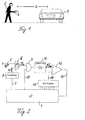
- FIG. 1 schematically shows a typical authentication process in a vehicle locking system designed as a keyless go system.
- the locking system is used to secure access of a passenger car 1, which is operated by a system user 2 can only be entered if an authentication element carried by him 3 valid for the vehicle in question 1 is what is checked with the authentication process.
- the Locking system is here with an electronic distance determination device equipped with which it can cover the distance D of the with its locking system part on the vehicle via an associated Authentication element communicating radio link 3 certainly. This serves, at least a part of the different, locking actions carried out by the locking system for Lockable and unlockable locking units on the vehicle doors and are arranged on the boot lid, depending on the determined Trigger distance D of the authentication element 3.
- a closing action can only be triggered by the locking system if the authentication element 3 not further than a predeterminable maximum distance away from vehicle 1.
- This maximum distance can for example in the range of a few meters.
- the authentication element 3 can be replaced by a chip card, a transponder or another common unit can be realized for this.
- the vehicle locking system can also be of a different type be, especially one in which the authentication elements from so-called electronic, from vehicle users to actuating keys are formed.
- the electronic distance determining device which in a such locking system, but also in other security systems of motor vehicles, e.g. electronic immobilizers, or of other mobile or stationary objects to be secured and general for determining the distance of any two objects can be provided below with reference to 2 to 6 explained in more detail.
- All of these range finding devices has in common that they are in one object, in the case of the locking system according to FIG. 1, preferably in the vehicle 1, a query and evaluation part and in the other object, in 1 in the respective authentication element 3, one Include answer part.
- the query and evaluation part generates an interrogation signal and emits it during the response part receives the transmitted interrogation signal and then an associated one Response signal generated and sent back.
- the query and Evaluation part determines one for the distance between it and the response part representative phase difference between the Interrogation signal and the response signal, so that the distance can be determined between the two objects in which the query and evaluation part or the answer part housed are.
- the result is below the further assumption that the query and response signals in Spread the shape of electromagnetic waves at the speed of light, a pure runtime for the outward journey of the query signal and the return path of the response signal of approx. 33ns.
- the query and response signals and the evaluation part evaluating them are to be interpreted so that phase differences of interrogation and Response signal showing such differences in transit time Correspond to the order of magnitude from a few nanoseconds, reliably recognized become.
- the distance determining device is like this designed that the query and the response signal are not from each need only exist a single pulse, their transit time difference is measured, but built up from pulse trains can be determined, the mutual phase difference becomes.
- FIG. 2 A first realization of a query and evaluation part suitable for this purpose is shown in FIG. 2. It contains as The core of a microprocessor 4, which is in the second top diagram Rectangular pulse signal FS reproduced from FIG. 3 as an interrogation signal generated and in a conventional, not shown Radiates via a transmission unit, not shown. The um removed the distance sought from the query and evaluation part Response part generated after receipt of that sent by the microprocessor 4 Query signal via an associated receiving unit same response signal AS, as in the top diagram of Fig. 3 is shown, and emits this via an associated Sender unit. The query and evaluation part receives this Response signal AS via a receiving unit, not shown, the it via a response signal line 5 to a first input of a Exclusive OR gate 6 supplies.
- a microprocessor 4 which is in the second top diagram Rectangular pulse signal FS reproduced from FIG. 3 as an interrogation signal generated and in a conventional, not shown Radiates via a transmission unit, not shown.
- the um removed the distance sought from the query and evaluation
- the microprocessor 4 the interrogation signal generated by him via a delay line 7 to a signal delay unit 8, so is designed to match the interrogation signal FS exactly around the signal processing time delays the response part for signal processing from the start of reception of the interrogation signal FS to needed to start sending the response signal AS. That way Delayed interrogation signal FS gives the delay unit 8 to a second input of the exclusive OR gate 6.
- the query signal FS and the response signal AS in one form, at which any of the signal processing time in the response part caused phase difference component is compensated.
- phase difference .DELTA.t as in the one above the other synchronously 3 is assumed as an example consequently, synchronism between interrogation signal FS and response signal AS provided only on the distance between query and Evaluation part on the one hand and response part on the other hand.
- AS the phase difference that occurs ⁇ t is therefore a clear measure of this distance.
- the exclusive OR gate 6 generates from the corresponding link of the supplied response signal AS and the suitably delayed Query signal FS, as shown in the two top diagrams 3 for an example case are shown Output signal OS, as it is for the example of FIG. 3 there second lowest diagram is shown. It lies according to of the selected exclusive-OR link is then always high Level when of the interrogation signal FS and the response signal AS one is high and the other is low. In other words, there is the output signal OS of the exclusive OR gate 6 from rectangular pulses with one of the distance-related Phase difference ⁇ t corresponding pulse width. It carries in this way the phase difference information with it.
- the output signal OS of the exclusive OR gate 6 is one Input of a subsequent AND gate 9 supplied, the other Input via a control line 10 from an associated one Control signal of the microprocessor 4 is applied.
- the AND gate 9 only serves to control the periods at which a distance evaluation by processing the output signal OS of the exclusive OR gate 6 is to take place. I agree for these periods, the microprocessor 4 acts on the associated one Input of AND gate 9 with a high signal level, so that the AND gate 9 the output signal OS of the exclusive OR gate 6 passes, while this signal transmission is blocked remains as long as the microprocessor 4 the associated input of AND gate 9 applied with a low signal level.
- An rms value generator 11 connects to the AND gate 9, the rectangular pulse output signal OS of the exclusive OR gate 6 transformed into a DC voltage signal GS as it reproduced for the example of Fig. 3 in the bottom diagram there is. Specifically, there is the initial increase in the DC voltage signal GS up to the effective voltage value Ue des Output signal OS of the exclusive OR gate 6 illustrated. Since this RMS value Ue clearly depends on the pulse width depends on this output signal OS, it is in the same Way like the width of its rectangular pulses a measure of that distance searched between the two objects. Thus, from the resulting effective rms value Ue the object distance sought be determined.
- Threshold value comparison unit In the query and evaluation part of FIG. 2 there is also one Threshold value comparison unit provided with which the RMS generator 11 determined rms voltage value with a variable threshold value can be compared.
- the threshold value comparison unit contains a comparator 12, the non-inverting input of the output signal GS of the RMS generator 11 is supplied, while its inverting Threshold voltage applied to input is the microprocessor 4 via a D / A converter 13 and a threshold line 14 is supplied. Via the microprocessor 4 the desired voltage threshold value can be varied can be set.
- the comparator 12 gives different Output signals via an evaluation line 15 to the microprocessor 4 from.
- the threshold value comparison unit With the threshold value comparison unit, tolerances of the different System components, especially the delay unit 8, and the signal processing time in the response part is balanced by adding a corresponding one to the respective real system Voltage threshold is set, one of such Manufacturing or operating tolerances caused phase difference compensated between query signal FS and response signal AS, the not on the finite signal transit time of the query and response signal between query and evaluation part on the one hand and answer part on the other hand. Furthermore, additional or as an alternative to a measure to correct these tolerances be provided, the threshold value comparison unit therefor use, by setting an appropriate voltage threshold define a distance threshold. How to from the above description of the different signals, the associated voltage rises as the voltage threshold increases Distance threshold.
- the microprocessor 4 can then use of the comparator output signal recognize whether the actual currently measured distance greater or smaller than the specified one Distance threshold is different depending on it carry out further control measures. So in the case of the locking system of Fig. 1 be provided that on this A certain maximum distance between the authentication element 3 and vehicle 1 is specified and triggering one Locking action of the locking system only takes place if that Authentication element 3 no further than the predetermined maximum distance away from vehicle 1.
- FIG. 4 and 5 are two further possible implementations for the query and evaluation part of the distance determining device shown, which is largely similar to that of FIG. 2 are the same reference numerals for functionally identical elements are used and in so far to the above description can be referred to Fig. 2.
- the query and evaluation part of FIG. 4 corresponds to that of Fig. 2 except that the threshold comparison unit is fully integrated into the microprocessor 4 and the analog comparator 12 and the D / A converter 13 of FIG. 2 are omitted.
- This system design can be chosen for the case that the microprocessor 4 contains an integrated A / D converter 4a, then the output signal GS of the RMS generator 11 is fed.
- This integrated A / D converter 4a converts the analog voltage rms value Ue of the rms generator output signal GS into an associated digital value by the microprocessor 4 itself with a digitally specified voltage threshold can be compared. Otherwise, the above apply Explanations of the threshold value comparison unit from FIG. 2 in same way for that in the case of Fig. 4 in the microprocessor 4 integrated threshold comparison unit.
- the output signal is evaluated OS of the exclusive-OR gate 6 via a capacitor charge time determination.
- this output signal OS via a Diode unit 16 and a resistor R1 to connect one Capacitor C performed, its opposite connection Mass is laid.
- a switching transistor is connected in parallel with capacitor C.
- T1 provided by the microprocessor 4 via a control signal can optionally be switched on and off, that from the microprocessor 4 via a control line 17 to the base of the transistor T1 is performed. This serves the evaluation part reset to the initial state after the evaluation process has ended and especially the capacitor C again completely discharge, for which the switching transistor T1 in its conductive state is controlled.
- the Switching transistor T1 controlled in its blocking state, and the Capacitor C is then replaced by the successive square wave pulses of the output signal OS of the exclusive OR gate 6 each according to the phase difference between the interrogation signal FS and the response signal AS charged more or less quickly.
- the time until A certain capacitor voltage value is thus reached representative of the phase difference between the interrogation signal FS and response signal AS and thus for the object distance sought.
- this is again done using a Threshold comparison unit further evaluated in that it is determined when the voltage across capacitor C is variable predeterminable voltage threshold value exceeds.
- the threshold value comparison unit consists of a Comparator 12a, at whose non-inverting input the Capacitor voltage is applied while at its inverting Input the threshold voltage, which is applied by means of a Voltage divider consisting of two resistors R2, R3 to a desired one Value can be set.
- the microprocessor 4 Comparator output signal supplied via an evaluation line 15a changes at the time the capacitor voltage exceeds the threshold voltage.
- the comparator output signal is the comparator output signal to a start / stop connection of a internal counter 4b, with the counter 4b in the microprocessor 4 with the initiation of a distance determination process is started.
- the comparator output signal that changes as a result stops the counter 4b, from which the capacitor charging time can be read, from which the associated object distance is derived.
- the capacitor charging time increases because of the narrowing rectangular pulses of the output signal OS of the Exclusive OR gate 6.
- the counter 4b is reset with the same control signal with which the microprocessor 4 the Switching transistor T1 turns on. As soon as this reset control signal is no longer present at the start of an evaluation process, the counter 4b starts running.
- the distance determining device can be used to measure larger distances with the following, not shown further Be equipped with additional functionality.
- the microprocessor in the query and evaluation part generates large for such a measurement Distances from e.g. over 100m a query signal in the form of a specifiable digital code word.
- the response part when received Code word a similar code word as a response signal generated and sent back. That from a receiving unit of the Query and evaluation part received response signal code word can be fed directly to the microprocessor for evaluation.
- the microprocessor maintains a simultaneous copy of the emitted interrogation signal code word of the signal delay unit to which it is about the signal processing time in the response part returns to the microprocessor after a delay.
- the microprocessor then checks the delayed interrogation signal codeword and the response signal code word for agreement or for a possible time shift of both code words.
- a term-related and therefore distance-related Time difference between interrogation signal and response signal code word can be recognized by more than 1 bit, so that with this procedure also reliably determine larger distances to let.
- the specification of a desired distance threshold may be provided, in particular in the form of a predetermined maximum bit shift between Interrogation signal and response signal code word. For example, be provided which correspond to a bit shift of 1 bit Specify object distance as distance threshold, i.e. depending on whether the compared code words by more or less than 1Bit are different, different measures according to the fact that then the two Objects at a greater or smaller distance than the distance threshold from each other.
- the accuracy of the distance determination, especially for the case of shorter distances is of importance increase that to the most exact possible Synchronization of the response signal sent back by the response part is respected relative to the query signal. Because deviations of this synchronicity can lead to phase differences between the interrogation and response signal, which are not dependent on the distance are.
- An advantageous way to ensure synchronization of the response signal with the interrogation signal provided by a structure of the response part as described in Fig. 6 is shown.
- the response part of the distance determination device shown there includes for response signal generation a voltage controlled oscillator (VCO) 18, the signal output at an output 19 via a first field-effect switching transistor T2 fed to a transmission unit, not shown which it emits as a response signal.
- VCO voltage controlled oscillator
- the interrogation signal sent by the interrogation and evaluation part becomes by the response part received via a receiving unit, not shown, and from this via an interrogation signal line 20 to the one input of a Exclusive-OR gate 21 supplied, the other input of the Output signal of the voltage-controlled oscillator 18 is applied becomes.
- the output of this exclusive OR gate 21 is connected via a first resistor R4 and a second field effect switching transistor T3 to a control input 22 of the voltage controlled Oscillator 18 created, on the other hand over a second resistor R5 and a capacitor C1 to ground is coupled.
- the two resistors R4, R5 and the capacitor C1 have a low pass for the output signal of the exclusive OR gate 21, so that the exclusive OR gate 21 along with this low pass and that voltage controlled oscillator 18 forms a PLL circuit, with which the response part is phase-locked to the received interrogation signal, generates and radiates an identical response signal.
- the voltage controlled oscillator 18 and the exclusive OR gate 21 together in one common integrated Circuit block may be included.
- the two switching transistors T2, T3 are from a microprocessor 23 of the response part controlled, the following mode of operation being feasible.
- the second field-effect switching transistor T3 opens so that capacitor C1 has a constant voltage maintained at the control input 22 of the voltage-controlled oscillator 18, with the help of the oscillator 18 continues to Interrogation signal generates a similar and phase-locked output signal.
- the first field effect switching transistor T2 becomes this synchronized output signal of the voltage controlled Oscillator 18 forwarded to the transmitter unit as a response signal and there as a response signal to the query and evaluation part Posted.
Landscapes
- Engineering & Computer Science (AREA)
- Radar, Positioning & Navigation (AREA)
- Remote Sensing (AREA)
- Computer Networks & Wireless Communication (AREA)
- Physics & Mathematics (AREA)
- General Physics & Mathematics (AREA)
- Lock And Its Accessories (AREA)
- Radar Systems Or Details Thereof (AREA)
- Selective Calling Equipment (AREA)
- Stabilization Of Oscillater, Synchronisation, Frequency Synthesizers (AREA)
Abstract
Description
- Fig. 1
- eine schematische Darstellung eines Authentikationsvorgangs mit Authentikationselement -Entfernungsbestimmung bei einer Fahrzeugschließanlage vom Keyless-go-Typ mit elektronischer Entfernungsbestimmungsvorrichtung,
- Fig. 2
- ein Blockschaltbild eines fahrzeugseitigen Abfrage- und Auswerteteils der für die Fahrzeugschließanlage von Fig. 1 verwendeten Entfernungsbestimmungsvorrichtung,
- Fig. 3
- Signalverlaufsdiagramme zur Veranschaulichung der Funktionsweise des Abfrage- und Auswerteteils von Fig. 2,
- Fig. 4
- ein Blockschaltbild einer Variante des Abfrage- und Auswerteteils von Fig. 2,
- Fig. 5
- ein Blockschaltbild einer weiteren Variante des Abfrage- und Auswerteteils von Fig. 2 und
- Fig. 6
- ein Blockschaltbild eines im Authentikationselement angeordneten Antwortteils der für die Fahrzeugschließanlage von Fig. 1 verwendeten Entfernungsbestimmungsvorrichtung.
Claims (8)
- Elektronische Vorrichtung zur Bestimmung der Entfernung zwischen zwei Objekten, insbesondere der Entfernung eines Authentikationselementes einer elektronischen Fahrzeugsicherungsanlage vom Fahrzeug, mitAbfragesignalerzeugungsmitteln (4) in einem ersten der beiden Objekte (1, 3) zum Erzeugen und Senden eines Abfragesignals (FS),Abfragesignalempfangsmitteln zum Empfangen des Abfragesignals (FS) und Antwortsignalerzeugungsmitteln (18) zum Erzeugen und Senden eines Antwortsignals (AS) im zweiten Objekt (3) auf den Empfang des Anfragesignals hin,Antwortsignalempfangsmitteln im ersten Objekt (1) zum Empfangen des Antwortsignals (AS) undeiner Auswerteeinheit (6 bis 11) im ersten Objekt zur Bestimmung der Entfernung zwischen den beiden Objekten anhand des Abfragesignals und des Antwortsignals,
dadurch gekennzeichnet, daßdie Auswerteeinheit (6 bis 11) zur Bestimmung einer entfernungsindikativen Phasendifferenz (Δt) zwischen dem Abfragesignal (FS) und dem Antwortsignal (AS) eingerichtet ist. - Elektronische Entfernungsbestimmungsvorrichtung nach Anspruch 1, weiter
dadurch gekennzeichnet, daß
im ersten Objekt (1) eine Signalverzögerungseinheit (8) vorgesehen ist, der das erzeugte Abfragesignal (FS) parallel zu einer Abfragesignalsendeeinheit zugeführt ist und die dieses um eine der Signalverarbeitungsdauer im zweiten Objekt (3) entsprechende Zeitdauer verzögert zum Vergleich mit dem empfangenen Antwortsignal (AS) weiterleitet. - Elektronische Entfernungsbestimmungsvorrichtung nach Anspruch 1 oder 2, weiter
dadurch gekennzeichnet, daß
die Antwortsignalerzeugungsmittel einen PLL-Schaltkreis mit einer Signalerzeugungseinheit (18) beinhalten, die getriggert vom empfangenen Abfragesignal (FS) ein dazu synchrones Antwortsignal (AS) erzeugt. - Elektronische Entfernungsbestimmungsvorrichtung nach einem der Ansprüche 1 bis 3, weiter
dadurch gekennzeichnet, daß
die Auswerteeinheit ein Exklusiv-ODER-Gatter (6) beinhaltet, dem eingangsseitig zum einen das Abfragesignal (FS) und zum anderen das empfangene Antwortsignal (AS) zugeführt sind. - Elektronische Entfernungsbestimmungsvorrichtung nach Anspruch 4, weiter
dadurch gekennzeichnet, daß
die Auswerteeinheit eine dem Exklusiv-ODER-Gatter (6) nachgeschaltete Effektivwertbildungseinheit (11) umfaßt und dieser eine Schwellwertvergleichseinheit (12-15) nachgeschaltet ist, die den von der Effektivwertbildungseinheit abgegebenen Spannungseffektivwert (Ue) mit einem fest oder variabel vorgebbaren Spannungsschwellwert vergleicht. - Elektronische Entfernungsbestimmungsvorrichtung nach Anspruch 4, weiter
dadurch gekennzeichnet, daß
das Ausgangssignal (OS) des Exklusiv-ODER-Gatters (6) an einen Ladeanschluß eines Kondensators (C) geführt ist und Ladezeitbestimmungsmittel (12a, 4b) vorgesehen sind, welche die Ladezeit des Kondensator (C) bis zum Erreichen eines fest oder variabel vorgebbaren Kondensatorspannungsschwellwertes bestimmen. - Elektronische Entfernungsbestimmungsvorrichtung nach einem der Ansprüche 1 bis 6, weiter
dadurch gekennzeichnet, daß
die Abfragesignalerzeugungsmittel (4) zur Erzeugung eines digitalen Codewortes als Abfragesignal und die Antwortsignalerzeugungsmittel zur Erzeugung eines dem Abfragesignal-Codewort entsprechenden Codewortes als Antwortsignal eingerichtet sind und die Auswerteeinheit die Phasendifferenz zwischen dem Abfragesignal-Codewort und dem Antwortsignal-Codewort ermittelt. - Elektronische Sicherungsanlage, insbesondere Fahrzeugschließanlage, miteinem oder mehreren, an einem ersten, zu sichernden Objekt (1) angeordneten Sicherungseinheiten,wenigstens einem berechtigenden Authentikationselement (3) als einem zweiten, nutzerseitig mitführbaren Objekt undAuthentikationselement-Erkennungsmitteln zur Feststellung, ob sich ein berechtigendes Authentikationselement innerhalb eines vorgebbaren Bereichs des zu sichernden Objektes befindet,
dadurch gekennzeichnet, daß
die Authentikationselement-Erkennungsmittel zur Bestimmung der Entfernung eines erkannten berechtigenden Authentikationselementes (3) vom zu sichernden Objekt (1) eingerichtet sind und hierzu eine elektronische Entfernungsbestimmungsvorrichtung nach einem der Ansprüche 1 bis 7 aufweisen.
Applications Claiming Priority (2)
| Application Number | Priority Date | Filing Date | Title |
|---|---|---|---|
| DE19909140 | 1999-03-03 | ||
| DE19909140A DE19909140A1 (de) | 1999-03-03 | 1999-03-03 | Elektronische Entfernungsbestimmungsvorrichtung und damit ausgerüstete elektronische Sicherungsanlage |
Publications (2)
| Publication Number | Publication Date |
|---|---|
| EP1033585A2 true EP1033585A2 (de) | 2000-09-06 |
| EP1033585A3 EP1033585A3 (de) | 2001-09-05 |
Family
ID=7899454
Family Applications (1)
| Application Number | Title | Priority Date | Filing Date |
|---|---|---|---|
| EP00102036A Withdrawn EP1033585A3 (de) | 1999-03-03 | 2000-02-02 | Elektronische Entfernungsbestimmungsvorrichtung und damit ausgerüstete elektronische Sicherungsanlage |
Country Status (5)
| Country | Link |
|---|---|
| US (1) | US6346878B1 (de) |
| EP (1) | EP1033585A3 (de) |
| JP (1) | JP3392385B2 (de) |
| KR (1) | KR20000076669A (de) |
| DE (1) | DE19909140A1 (de) |
Cited By (12)
| Publication number | Priority date | Publication date | Assignee | Title |
|---|---|---|---|---|
| WO2002025040A1 (en) * | 2000-09-22 | 2002-03-28 | Australian Arrow Pty Ltd | Proximity activated entry system |
| WO2002054353A1 (de) * | 2000-12-29 | 2002-07-11 | Siemens Aktiengesellschaft | Identifikationssystem zum nachweis einer berechtigung für den zugang zu einem objekt oder die benutzung eines objekts, insbesondere eines kraftfahrzeugs |
| DE10247719A1 (de) * | 2002-10-12 | 2004-04-22 | Conti Temic Microelectronic Gmbh | Verfahren zur Ermittlung des Abstands zwischen zwei Sende-Empfangs-Stationen und Sende-Empfangs-Stationen zur Durchführung des Verfahrens |
| DE10247718A1 (de) * | 2002-10-12 | 2004-04-22 | Conti Temic Microelectronic Gmbh | Verfahren zur Ermittlung des Abstands zwischen einer ersten und zweiten Sende-Empfangs-Station |
| DE10247713A1 (de) * | 2002-10-12 | 2004-04-22 | Conti Temic Microelectronic Gmbh | Verfahren zur Ermittlung des Abstands zwischen zwei Sende-Empfangs-Stationen |
| EP2009538A1 (de) * | 2007-06-25 | 2008-12-31 | Sitronic Ges. Für Elektrotechnische Ausrüstung Mbh & Co. Kg | Elektronisches Modul und Anordnung zur Signalübertragung damit |
| US7641726B2 (en) | 2006-04-11 | 2010-01-05 | Fujifilm Imaging Colorants Limited | Phthalocyanines and their use in ink-jet printing |
| WO2013053860A1 (fr) * | 2011-10-11 | 2013-04-18 | Johnson Controls Automotive Electronics Sas | Systeme de controle a distance et procede pour verrouiller et/ou pour deverrouiller automatiquement au moins un ouvrant d'un vehicule automobile et/ou pour demarrer un moteur d'un vehicule automobile a l'aide d'un systeme de controle a distance |
| WO2013110596A1 (fr) | 2012-01-26 | 2013-08-01 | Johnson Controls Automotive Electronics Sas | Moyen d'authentification portable et système de sécurité de véhicule pour un véhicule automobile |
| WO2018137923A1 (de) * | 2017-01-27 | 2018-08-02 | Continental Automotive Gmbh | Verfahren zum verifizieren eines vorgegebenen räumlichen maximalabstands eines funkschlüssels bezüglich eines kraftfahrzeugs sowie steuervorrichtung, kraftfahrzeug und funkschlüssel |
| DE102004030458B4 (de) | 2004-04-14 | 2018-12-20 | Conti Temic Microelectronic Gmbh | Verfahren zur Signalübertragung und Verwendung des Verfahrens |
| WO2019238789A1 (en) * | 2018-06-14 | 2019-12-19 | Fraunhofer-Gesellschaft zur Förderung der angewandten Forschung e.V. | Method for determining a relay attack, relay attack detecting device, and computer program |
Families Citing this family (32)
| Publication number | Priority date | Publication date | Assignee | Title |
|---|---|---|---|---|
| GB2358427B (en) * | 2000-01-21 | 2004-01-21 | Roke Manor Research | Automatic locking system |
| US6529142B2 (en) * | 2000-07-24 | 2003-03-04 | Shipong Norman Yeh | Parked vehicle location finder |
| DE10049371A1 (de) * | 2000-10-05 | 2002-04-11 | Hella Kg Hueck & Co | Zentralverriegelung und Verfahren zur Betätigung dieser Zentralverriegelung |
| SE519748C2 (sv) * | 2000-10-23 | 2003-04-08 | Volvo Technology Corp | Förfarande för kontroll av behörighet för tillträde till ett objekt samt datorprogramprodukten för utförande av förfaranden |
| GB2390508A (en) * | 2002-07-03 | 2004-01-07 | Marconi Information Systems Lt | Variable frequency tag and interogation system |
| CN1672382B (zh) | 2002-07-26 | 2010-09-01 | 皇家飞利浦电子股份有限公司 | 安全验证的距离测量 |
| DE10238887A1 (de) * | 2002-08-24 | 2004-03-04 | Robert Bosch Gmbh | Verfahren und System zur bidirektionalen Datenübertragung und Entfernungsbestimmung |
| DE10259027B4 (de) * | 2002-12-16 | 2011-07-28 | Leopold Kostal GmbH & Co. KG, 58513 | NF-Sendemodul für eine schlüssellose Nutzungsberechtigungskontrolleinrichtung sowie Verfahren zum Senden von Weck-und Ortungssignalen im Rahmen einer schlüssellosen Nutzungsberechtigungskontrolle |
| EP1467322A3 (de) * | 2003-04-08 | 2005-10-12 | Brose Schliesssysteme GmbH & Co. KG | Kraftfahrzeug-Türschliesssystem |
| US7145507B2 (en) * | 2003-12-16 | 2006-12-05 | Lear Corporation | Vehicle locating system using GPS |
| EP1741019A1 (de) * | 2004-04-29 | 2007-01-10 | Bayerische Motoren Werke Aktiengesellschaft | Authentisierung von steuergeräten in einem fahrzeug |
| CN1977279B (zh) * | 2004-06-15 | 2011-02-23 | Nxp股份有限公司 | 具有附加近距离校验的无线电识别 |
| GB0415219D0 (en) * | 2004-07-07 | 2004-08-11 | Koninkl Philips Electronics Nv | Improvements in or relating to time-of-flight ranging systems |
| US20090206989A1 (en) * | 2004-09-30 | 2009-08-20 | Nxp B.V. | Electronic communication system, in particular access control system for p(assive)k(eyless)e(ntry), as well as method for detecting a relay attack thereon |
| US7466219B2 (en) * | 2004-10-19 | 2008-12-16 | Sanyo Electric Co., Ltd. | Communication device and distance calculation system |
| US7397344B2 (en) * | 2005-01-06 | 2008-07-08 | Lear Corporation | Dual range vehicle remote |
| JP4501719B2 (ja) * | 2005-02-22 | 2010-07-14 | トヨタ自動車株式会社 | 車両遠隔操作装置 |
| US8886125B2 (en) | 2006-04-14 | 2014-11-11 | Qualcomm Incorporated | Distance-based association |
| US9215581B2 (en) | 2006-04-14 | 2015-12-15 | Qualcomm Incorported | Distance-based presence management |
| US8552903B2 (en) * | 2006-04-18 | 2013-10-08 | Qualcomm Incorporated | Verified distance ranging |
| WO2007128319A2 (en) * | 2006-06-14 | 2007-11-15 | Scandlife Italia Aps | Locking system and remote-controlled entry system |
| US8837724B2 (en) | 2007-03-27 | 2014-09-16 | Qualcomm Incorporated | Synchronization test for device authentication |
| US9524502B2 (en) | 2007-06-20 | 2016-12-20 | Qualcomm Incorporated | Management of dynamic electronic coupons |
| US9141961B2 (en) | 2007-06-20 | 2015-09-22 | Qualcomm Incorporated | Management of dynamic mobile coupons |
| US9483769B2 (en) | 2007-06-20 | 2016-11-01 | Qualcomm Incorporated | Dynamic electronic coupon for a mobile environment |
| US10542372B2 (en) | 2011-03-15 | 2020-01-21 | Qualcomm Incorporated | User identification within a physical merchant location through the use of a wireless network |
| WO2013020105A2 (en) * | 2011-08-04 | 2013-02-07 | Rambus Inc. | Low-cost tracking system |
| CN104246576B (zh) * | 2012-01-30 | 2018-07-31 | 徕卡显微系统复合显微镜有限公司 | 具有无线接口的显微镜和显微镜系统 |
| MX2015004817A (es) * | 2012-11-16 | 2016-02-10 | Ericsson Telefon Ab L M | Autenticacion de multiples factores basada en alrededores. |
| JP6188132B2 (ja) * | 2013-06-21 | 2017-08-30 | Kddi株式会社 | 距離測定システム及び送受信機 |
| JP6636817B2 (ja) * | 2016-02-15 | 2020-01-29 | 株式会社東海理化電機製作所 | 通信不正成立防止システム及び電子キーシステム |
| DE102018209256A1 (de) * | 2018-06-11 | 2019-12-12 | Bayerische Motoren Werke Aktiengesellschaft | Verfahren und vorrichtung zum nicht-mechanischen betätigen einer verschlussanordnung |
Family Cites Families (13)
| Publication number | Priority date | Publication date | Assignee | Title |
|---|---|---|---|---|
| US4249176A (en) * | 1974-01-28 | 1981-02-03 | Nippon Soken, Inc. | Following distance measuring communication system |
| CH614051A5 (de) * | 1977-04-07 | 1979-10-31 | Siemens Ag Albis | |
| US5293160A (en) * | 1989-11-02 | 1994-03-08 | Nissan Motor Company, Ltd. | Keyless vehicle lock system with distance measuring |
| JP3288478B2 (ja) * | 1992-04-29 | 2002-06-04 | テキサス インスツルメンツ インコーポレイテツド | 環境条件を遠隔感知する識別システム |
| DE4240491C2 (de) * | 1992-12-02 | 1996-10-31 | Grieshaber Vega Kg | Vorrichtung zur Laufzeitmessung, insbesondere Entfernungsmessung |
| US5533045A (en) * | 1993-02-05 | 1996-07-02 | Matsushita Electric Industrial Co., Ltd. | Automatic vehicle identification system, interrogator and responder included in the same |
| DE4436605A1 (de) * | 1993-10-15 | 1995-04-20 | Joachim Linz | Verfahren zur sicheren Ver- und Entriegelung von Schlössern mit einer Authentisierung |
| DE4407369C2 (de) * | 1994-03-05 | 1999-09-30 | Grieshaber Vega Kg | Verfahren und Schaltungsanordnung zur Laufzeitmessung sowie deren Verwendung |
| DE4436983A1 (de) * | 1994-10-06 | 1996-04-11 | Siemens Ag | Verfahren zum Bestimmen des Abstandes zwischen einem Bezugspunkt und einem Fahrzeug und Einrichtung zur Durchführung des Verfahrens |
| DE4440855C2 (de) * | 1994-11-15 | 2000-04-06 | Simons & Vos Identifikationssy | Kontrollsystem |
| US5673018A (en) * | 1995-06-07 | 1997-09-30 | Palomar Technologies Corporation | Transponder system for reporting the distance traveled by a wheeled vehicle |
| FR2740501B1 (fr) * | 1995-10-26 | 1998-06-19 | Valeo Securite Habitacle | Systeme mains libres de deverrouillage et/ou d'ouverture d'ouvrant de vehicule automobile |
| DE19632025C2 (de) * | 1996-08-08 | 1998-07-23 | Daimler Benz Ag | Authentikationseinrichtung mit elektronischer Authentikationskommunikation |
-
1999
- 1999-03-03 DE DE19909140A patent/DE19909140A1/de not_active Withdrawn
-
2000
- 2000-02-02 EP EP00102036A patent/EP1033585A3/de not_active Withdrawn
- 2000-02-16 KR KR1020000007216A patent/KR20000076669A/ko not_active Ceased
- 2000-03-01 JP JP2000056456A patent/JP3392385B2/ja not_active Expired - Fee Related
- 2000-03-03 US US09/518,192 patent/US6346878B1/en not_active Expired - Lifetime
Cited By (16)
| Publication number | Priority date | Publication date | Assignee | Title |
|---|---|---|---|---|
| WO2002025040A1 (en) * | 2000-09-22 | 2002-03-28 | Australian Arrow Pty Ltd | Proximity activated entry system |
| WO2002054353A1 (de) * | 2000-12-29 | 2002-07-11 | Siemens Aktiengesellschaft | Identifikationssystem zum nachweis einer berechtigung für den zugang zu einem objekt oder die benutzung eines objekts, insbesondere eines kraftfahrzeugs |
| US7098769B2 (en) | 2000-12-29 | 2006-08-29 | Siemens Aktiengesellschaft | Identification system for verifying an authorization to access an object or to use an object, particularly a motor vehicle |
| DE10247719A1 (de) * | 2002-10-12 | 2004-04-22 | Conti Temic Microelectronic Gmbh | Verfahren zur Ermittlung des Abstands zwischen zwei Sende-Empfangs-Stationen und Sende-Empfangs-Stationen zur Durchführung des Verfahrens |
| DE10247718A1 (de) * | 2002-10-12 | 2004-04-22 | Conti Temic Microelectronic Gmbh | Verfahren zur Ermittlung des Abstands zwischen einer ersten und zweiten Sende-Empfangs-Station |
| DE10247713A1 (de) * | 2002-10-12 | 2004-04-22 | Conti Temic Microelectronic Gmbh | Verfahren zur Ermittlung des Abstands zwischen zwei Sende-Empfangs-Stationen |
| DE102004030458B4 (de) | 2004-04-14 | 2018-12-20 | Conti Temic Microelectronic Gmbh | Verfahren zur Signalübertragung und Verwendung des Verfahrens |
| US7641726B2 (en) | 2006-04-11 | 2010-01-05 | Fujifilm Imaging Colorants Limited | Phthalocyanines and their use in ink-jet printing |
| EP2009538A1 (de) * | 2007-06-25 | 2008-12-31 | Sitronic Ges. Für Elektrotechnische Ausrüstung Mbh & Co. Kg | Elektronisches Modul und Anordnung zur Signalübertragung damit |
| WO2013053860A1 (fr) * | 2011-10-11 | 2013-04-18 | Johnson Controls Automotive Electronics Sas | Systeme de controle a distance et procede pour verrouiller et/ou pour deverrouiller automatiquement au moins un ouvrant d'un vehicule automobile et/ou pour demarrer un moteur d'un vehicule automobile a l'aide d'un systeme de controle a distance |
| WO2013110596A1 (fr) | 2012-01-26 | 2013-08-01 | Johnson Controls Automotive Electronics Sas | Moyen d'authentification portable et système de sécurité de véhicule pour un véhicule automobile |
| CN104169978A (zh) * | 2012-01-26 | 2014-11-26 | 约翰逊控制器汽车电子公司 | 用于机动车辆的便携式认证装置和车辆安全系统 |
| WO2018137923A1 (de) * | 2017-01-27 | 2018-08-02 | Continental Automotive Gmbh | Verfahren zum verifizieren eines vorgegebenen räumlichen maximalabstands eines funkschlüssels bezüglich eines kraftfahrzeugs sowie steuervorrichtung, kraftfahrzeug und funkschlüssel |
| US11217047B2 (en) | 2017-01-27 | 2022-01-04 | Continental Automotive Gmbh | Method for verifying a predefined maximum spatial distance of a radio key in relation to a motor vehicle, as well as control device, motor vehicle and radio key |
| WO2019238789A1 (en) * | 2018-06-14 | 2019-12-19 | Fraunhofer-Gesellschaft zur Förderung der angewandten Forschung e.V. | Method for determining a relay attack, relay attack detecting device, and computer program |
| US11348388B2 (en) | 2018-06-14 | 2022-05-31 | Fraunhofer-Gesellschaft Zur Foerderung Der Angewandten Forschung E.V. | Method for determining a relay attack, relay attack detecting device, and computer program |
Also Published As
| Publication number | Publication date |
|---|---|
| EP1033585A3 (de) | 2001-09-05 |
| JP3392385B2 (ja) | 2003-03-31 |
| US6346878B1 (en) | 2002-02-12 |
| DE19909140A1 (de) | 2000-09-21 |
| KR20000076669A (ko) | 2000-12-26 |
| JP2000275328A (ja) | 2000-10-06 |
Similar Documents
| Publication | Publication Date | Title |
|---|---|---|
| DE19909140A1 (de) | Elektronische Entfernungsbestimmungsvorrichtung und damit ausgerüstete elektronische Sicherungsanlage | |
| EP0983916B1 (de) | Schliesssystem, insbesondere für ein Kraftfahrzeug | |
| EP1505734B1 (de) | Kapazitiver Näherungsschalter | |
| DE102014010668B4 (de) | Passives schlüsselloses Ferneintrittssystem mit einer niveau-basierten Anti-Diebstahl-Eigenschaft | |
| DE19957536C2 (de) | Diebstahlschutzsystem für ein Kraftfahrzeug und Verfahren zum Betreiben eines Diebstahlschutzsystems | |
| EP1185881B1 (de) | Entfernungsmesseinrichtung und verfahren zum kalibrieren einer entfernungsmesseinrichtung | |
| EP0813321A2 (de) | Verfahren und Steuersystem zum Übertragen von Daten | |
| DE978046C (de) | Impulsradargeraet mit einer Anordnung zur entstoerenden Auswahl einer Zufallsfrequenz | |
| EP0772058A2 (de) | Identifizierungs- und/oder Sensorsystem | |
| DE2514664A1 (de) | Basisband-funkerfassungssystem | |
| DE102014112124B4 (de) | Vorrichtung und verfahren zum auswerten der leistung einessystems in einer regelschleife | |
| DE102015115018B4 (de) | Kombinierter Lock-/out-of-Lock-Detektor für Phasenregelkreise | |
| DE102017211941A1 (de) | Verfahren zum Ermitteln einer Zugangsberechtigung zu einem Kraftfahrzeug sowie Berechtigungssystem für ein Kraftfahrzeug | |
| EP0676650B1 (de) | Verfahren zur Entfernungsmessung mit Hilfe einer Funkstrecke und Anordnung zur Durchführung des Verfahrens | |
| DE19939365C2 (de) | Verfahren und Anordnung zum Identifizieren einer zu einer Basisstation gehörenden Mobilstation | |
| EP0318689B1 (de) | Verfahren und Schaltungsanordnung zur Frequenznachstimmung einer Frequenzquelle | |
| DE602005003573T2 (de) | Jitter-messung | |
| DE2531102A1 (de) | Radargeraet zum senden und empfangen von impulszuegen mit von impuls zu impuls unterschiedlicher frequenz | |
| EP0612410B1 (de) | Abtastverfahren für verjitterte signale | |
| DE102020120920B4 (de) | Verfahren zur Bestimmung einer Entfernung | |
| DE19732873A1 (de) | Verfahren und Vorrichtung zur Synchronisierung der Datenübertragung zwischen einem dezentralen Satellitengerät und einem zentralen Steuergerät in einem Kraftfahrzeug | |
| DE102021006165A1 (de) | Verfahren zum Betrieb eines Zugangssystems des Fahrzeugs | |
| DE19624846C1 (de) | Diebstahlschutzsystem für ein Kraftfahrzeug | |
| DE10310157B4 (de) | Verfahren und Einrichtung zur Elimination der Oszillator-Drift in einem Zugangskontrollsystem | |
| DE1941899A1 (de) | Anordnung zum Synchronisieren von Zeitgebern |
Legal Events
| Date | Code | Title | Description |
|---|---|---|---|
| PUAI | Public reference made under article 153(3) epc to a published international application that has entered the european phase |
Free format text: ORIGINAL CODE: 0009012 |
|
| AK | Designated contracting states |
Kind code of ref document: A2 Designated state(s): DE ES FR GB IT Kind code of ref document: A2 Designated state(s): AT BE CH CY DE DK ES FI FR GB GR IE IT LI LU MC NL PT SE |
|
| AX | Request for extension of the european patent |
Free format text: AL;LT;LV;MK;RO;SI |
|
| PUAL | Search report despatched |
Free format text: ORIGINAL CODE: 0009013 |
|
| AK | Designated contracting states |
Kind code of ref document: A3 Designated state(s): AT BE CH CY DE DK ES FI FR GB GR IE IT LI LU MC NL PT SE |
|
| AX | Request for extension of the european patent |
Free format text: AL;LT;LV;MK;RO;SI |
|
| 17P | Request for examination filed |
Effective date: 20010822 |
|
| AKX | Designation fees paid |
Free format text: DE ES FR GB IT |
|
| RAP1 | Party data changed (applicant data changed or rights of an application transferred) |
Owner name: DAIMLERCHRYSLER AG |
|
| RAP1 | Party data changed (applicant data changed or rights of an application transferred) |
Owner name: DAIMLER AG |
|
| STAA | Information on the status of an ep patent application or granted ep patent |
Free format text: STATUS: THE APPLICATION IS DEEMED TO BE WITHDRAWN |
|
| 18D | Application deemed to be withdrawn |
Effective date: 20070901 |