EP1032022A1 - Metallhalogenidlampe mit keramischem Entladungsgefäss - Google Patents
Metallhalogenidlampe mit keramischem Entladungsgefäss Download PDFInfo
- Publication number
- EP1032022A1 EP1032022A1 EP00100687A EP00100687A EP1032022A1 EP 1032022 A1 EP1032022 A1 EP 1032022A1 EP 00100687 A EP00100687 A EP 00100687A EP 00100687 A EP00100687 A EP 00100687A EP 1032022 A1 EP1032022 A1 EP 1032022A1
- Authority
- EP
- European Patent Office
- Prior art keywords
- rare earth
- ceramic
- cermet
- halide lamp
- metal halide
- Prior art date
- Legal status (The legal status is an assumption and is not a legal conclusion. Google has not performed a legal analysis and makes no representation as to the accuracy of the status listed.)
- Granted
Links
Images

Classifications
-
- H—ELECTRICITY
- H01—ELECTRIC ELEMENTS
- H01J—ELECTRIC DISCHARGE TUBES OR DISCHARGE LAMPS
- H01J61/00—Gas-discharge or vapour-discharge lamps
- H01J61/02—Details
- H01J61/36—Seals between parts of vessels; Seals for leading-in conductors; Leading-in conductors
Definitions
- the invention is based on a metal halide lamp with a ceramic discharge vessel according to the preamble of claim 1. It is in particular around metal halide lamps with an output of at least 100 W.
- a generic metal halide lamp with a ceramic discharge vessel and a halide-resistant bushing is already known from EP-A 587 238.
- the front part of the bushing facing the discharge can consist of an electrically conductive cermet (with a ceramic and a conductive phase).
- Aluminum oxide or also MgO, Sc 2 O 3 or Y 2 O 3 is used as the ceramic phase.
- a halogen-resistant metal, for example tungsten, or molybdenum disilicide (MoSi 2 ) is proposed as the conductive phase of the cermet.
- Filling components made from rare earth metal halides (SE) are usually used in these lamps.
- DyJ 3 is recommended.
- the use of the iodides of Sc, Y, Ho or Tm is recommended.
- EP-A 887 839 recommends using a continuous cermet stick to be used for metal halide lamps with ceramic discharge tube.
- the starting point of the present invention is the discovery that due to the high temperature in the area of the face of the binding carrying out Rare earth metal ions from the filling preferably in the region of a front zone Implementation takes place, at least the surface of the part of the implementation that with is in contact with the discharge volume. Most of them are the frontal discharge end of the bushing as it is the highest temperature reached in operation. In contrast, the discharge vessel itself and the sealant (usually a stopper) significantly less affected.
- the front part is a cermet component with a ceramic and an electrically conductive Phase.
- the ceramic phase of the cermet component either the entire one Component or a zone on the surface facing the discharge from from the outset a considerable proportion (especially at least 40, especially more than 80 mol%) of a corresponding compound made of the ceramic base material and at least one rare earth oxide, the Germet component or its zone exposed to discharge, no longer bind rare earth metal from the filling. Therefore, the filling and thus the maintenance of the lamp over a long service life stable without using an overdose of the filling got to.
- the surface with a garnet or perovskite structure can be on the front and possibly also on the lateral surface of the cermet component.
- the invention is a metal halide lamp ceramic discharge vessel, the discharge vessel having two ends which are sealed with means for sealing.
- electrically conductive bushing passed through vacuum-tight, on which an electrode is fastened with a shaft which projects into the interior of the discharge vessel.
- At least a front part of the feedthrough that faces the discharge is designed as a halide-resistant component made of electrically conductive cermet, that of an electrically conductive (especially metallic) and a ceramic Phase, which comprises a ceramic base material.
- the filling comprises at least a rare earth metal (i.e. Sc, Y, La and the 14 lanthanoids), mostly as a halide, or as a complex or elementary.
- At least on the face (Front) of the component consists of at least part of the ceramic phase Connection of the ceramic base material with one or more rare earth oxides.
- the cermet component is preferably a pin or a tube.
- the cermet usually has a metal such as molybdenum or tungsten or rhenium or their alloys or a metal silicide such as MoSi 2 as the electrically conductive phase.
- the safest is when it covers the entire area Length of the component at least part of the ceramic phase from the connection of the ceramic base material with one or more rare earth oxides consists.
- the entire ceramic phase preferably consists of the connection of the ceramic base material and one or more rare earth oxides.
- the Cermet component can carry out the front part or the whole Form implementation.
- the ceramic base material is usually polycrystalline aluminum oxide.
- those used for the cermet component include Rare earth metal oxides are the oxides of one or more or all of them in the filling contained rare earth metals.
- the rare earth oxides comprise the oxides of one or more rare earth metals not contained in the filling, in particular Y 2 O 3 .
- Embodiment corresponds to the connection of the ceramic base material with one or more rare earth oxides Garnet or perovskite or a mixture of both.
- a perovskite preferably oxides of La, Nd, Sm, Eu or Gd are used.
- oxides of Lu, Yb, Tm and Y are particularly suitable for both structures and their mixtures.
- This special cermet component is used in all metal halide lamps possible with ceramic discharge vessel, regardless of whether the seal by means of melting ceramics or by direct sintering.
- the production of the special cermet can be carried out in a manner known per se by processing an appropriate powder mixture.
- the basic Suitability of such materials (especially yttrium aluminum garnet) for the lamp construction is already known, see US-A 5 698 948. There the material however used for discharge vessels. The requirement of Translucency does not matter in the implementation.
- the means for sealing (usually a stopper) is advantageously made of ceramic or Cermet (for example, suitably doped aluminum oxide), the ceramic Base material of the cermet component is a ceramic main component of the agent corresponds to sealing, here aluminum oxide.
- This arrangement has the advantage that the thermal expansion coefficients of the two parts are similar, so that a direct sintering of the cermet component in the stopper is particularly successful.
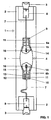
- a metal halide lamp with an output of 250 W is shown schematically in FIG. It consists of a cylindrical outer bulb 1 made of quartz glass which defines a lamp axis and is squeezed (2) and base (3) on two sides.
- the axially arranged discharge vessel 4 made of Al 2 O 3 ceramic is bulged in the middle 5 and has two cylindrical ends 6a and 6b. It is held in the outer bulb 1 by means of two power leads 7, which are connected to the base parts 3 via foils 8.
- the power supply lines 7 are welded to bushings 9, 10, which are each fitted in an end plug 11 at the end of the discharge vessel.
- the bushings 9, 10 are cermet pins with a diameter of approx. 1 mm, which consist of an electrically conductive cermet.
- Both bushings 9, 10 extend over the entire length of the plug 11 and hold electrodes 14 on the discharge side, consisting of an electrode shaft 15 made of tungsten and one pushed on at the discharge end Spiral 16.
- the bushing 9, 10 is in each case with the electrode shaft 15 and butt welded to the external power supply 7.
- the discharge vessel is filled with an inert ignition gas, e.g. Argon, and possibly mercury from additives to metal halides, thereof at least one rare earth metal.
- an inert ignition gas e.g. Argon
- mercury from additives to metal halides, thereof at least one rare earth metal.
- End plugs 11 are used as means for sealing, which essentially consist of Al 2 O 3 , for example. It is also possible to use a non-conductive cermet with the main component Al 2 O 3 , with tungsten being present as a metallic component in a proportion of approximately 30% by weight (or molybdenum with a correspondingly higher proportion).
- the bushing 9, 10 is sintered directly into the plug 11. More like that The plug 11 is also in each case in the cylindrical end 6 of the discharge vessel sintered directly (i.e. without glass solder or melting ceramic).
- This bore 12 is made after filling by means of a pen 13 or closed by means of melting ceramic.
- the pen usually consists of Ceramics or cermet.
- a cermet pen is suitable as a lead-through 9, 10 which, in addition to the ceramic phase with the base material aluminum oxide at least 44% by volume Contains metal (preferably between 45 and 75 vol .-%) and is electrically conductive. In particular 70 to 90% by weight of tungsten or 55 to 80% by weight of molybdenum is suitable (or an amount of rhenium equivalent in volume).
- the ceramic Phase consists entirely of garnet (see below).
- a cermet with a lower percentage is suitable as the material for the end plug of metal as the feedthrough (preferably about half the proportion in the Implementation) contains.
- An essential property of the stopper is that its coefficient of thermal expansion between that of the implementation and that of the Discharge vessel is.
- the metal content of the stopper can also be zero.
- cermet component was used, that from the outset as the ceramic phase, for example the natural one Equilibrium distribution used and thus anticipates this diffusion process:
- a regular garnet using only Tm 2 O 3 as the rare earth oxide with aluminum oxide as the base material was used as the ceramic phase for this cermet component.
- Sc 2 O 3 (or also Yb 2 O 3 ) is used as the rare earth metal oxide. Both ions have a smaller ion radius (0.075 or 0.087 nm) than the rare earth metal ions used in the filling. The lifetime achieved with this corresponds approximately to that of the second exemplary embodiment.
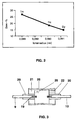
- a second embodiment is at the ends of the approximately circular cylindrical Discharge vessel 25 each sintered a non-conductive plug 26 directly.
- the implementation is an electrically conductive cermet pin 9, 10 with a Metal content of 50% by volume.
- the rest is a ceramic phase.
- the plug 26 out Aluminum oxide consists of two concentric parts, an outer annular one Plug part 21 and an inner, about twice as long capillary tube 20. Nevertheless the capillary tube is about 50% compared to known capillary tube techniques shorter. The large length of the capillary tube compared to the plug part 21 improved the sealing behavior.
- the cermet pin 9 is recessed in the capillary tube 20 and sintered there directly.
- the filling bore 22 is in the outer plug part 21 housed.
- an Eu 2 O 3 perovskite structure is used as the ceramic phase only on its end face 19 over an axial length of about 1 mm, which gradually changes into the known structure with pure aluminum oxide phase in a subsequent transition zone, which is used at the end of the pen.
- Figure 4 shows a cermet pin 27 which is composed of two parts.
- the front front part 28 has a garnet structure as the ceramic phase with aluminum oxide as the base material and Er 2 O 3 as the rare earth oxide. It has an axial nose 29 with which it is fitted in a circular cylindrical bore of an extension part 30 arranged behind it. Both parts are connected by direct sintering.
- the front part 32 and the extension part 33 are approximately the same length.
- YAG yttrium aluminum garnet, 3 Y 2 O 3 .5 Al 2 O 3
- YAG yttrium aluminum garnet, 3 Y 2 O 3 .5 Al 2 O 3
- FIG. 6 shows a further exemplary embodiment in which the end of the cylindrical ceramic discharge vessel 40 (made of aluminum oxide) is closed by a ceramic end plate 41 and a tubular plug 42.
- a two-part bushing 43 is sealed in the stopper by means of glass dead 44.
- the bushing 43 consists of a discharge-side cermet pin 45 and a niobium pin 46 facing away from the discharge.
- the electrode 47 is fastened to the cermet pin.
- the surface of the cermet stick is covered by a 300 ⁇ m thick layer 48 of YAG.
- the conductive phase (60% by volume) of the cermet stick consists of MoSi 2
- the ceramic phase (rest) consists of 50 mol% Al 2 O 3 and 50 mol% a mixture of YAG and Eu 2 O 3 - Perovskite.
- the filling contains DyJ 3 and CeJ 3 as rare earth metal iodides.
Landscapes
- Vessels And Coating Films For Discharge Lamps (AREA)
- Discharge Lamps And Accessories Thereof (AREA)
- Discharge Lamp (AREA)
Abstract
Description
- Figur 1
- eine Metallhalogenidlampe, im Schnitt
- Figur 2
- den Anteil verschiedener Seltenerdmetalle im Cermetstift
- Figur 3
- das Entladungsgefäß einer Metallhalogenidlampe, im Schnitt
- Figur 4
- ein weiteres Ausführungsbeispiel eines Cermetstifts
- Figur 5
- noch ein weiteres Ausführungsbeispiel eines Cermetstifts
- Figur 6
- ein weiteres Ausführungsbeispiel eines Entladungsgefäßes im Schnitt
Claims (13)
- Metallhalogenidlampe mit keramischem Entladungsgefäß (4), wobei das Entladungsgefäß zwei Enden (6) besitzt, die mit Mitteln zum Abdichten verschlossen sind, und wobei durch diese Mittel eine elektrisch leitende Durchführung (9,10;30) vakuumdicht hindurchgeführt ist, an der eine Elektrode (14) befestigt ist, die in das Innere des Entladungsgefäßes hineinragt, wobei zumindest ein vorderer Teil (45) der Durchführung, der der Entladung zugewandt ist, als ein halogenidresistentes Bauteil aus elektrisch leitendem Cermet gestaltet ist, das aus einer ersten elektrisch leitenden Phase und einer zweiten keramischen Phase, die ein keramisches Basismaterial umfaßt, und wobei die Füllung mindestens ein Seltenerdmetall umfaßt, dadurch gekennzeichnet, daß zumindest an einer der Füllung zugänglichen Oberfläche (28;32) des Cermet-Bauteils zumindest ein Teil der keramischen Phase aus der Verbindung des keramischen Basismaterials mit einem oder mehreren Seltenerdmetall-Oxiden besteht.
- Metallhalogenidlampe nach Anspruch 1, dadurch gekennzeichnet, daß das Bauteil aus Cermet die Gestalt eines Cermet-Stifts (9,10) besitzt.
- Metallhalogenidlampe nach Anspruch 1, dadurch gekennzeichnet, daß das Cermet als elektrisch leitende Phase Molybdän oder Wolfram oder Rhenium oder deren Legierungen oder MoSi2 besitzt.
- Metallhalogenidlampe nach Anspruch 1, dadurch gekennzeichnet, daß beim gesamten Bauteil ein Teil der keramischen Phase aus der Verbindung des keramischen Basismaterials und einem oder mehreren Seltenerdmetall-Oxiden besteht.
- Metallhalogenidlampe nach Anspruch 1, dadurch gekennzeichnet, daß die gesamte keramische Phase aus der Verbindung des keramischen Basismaterials und einem oder mehreren Seltenerdmetall-Oxiden besteht.
- Metallhalogenidlampe nach Anspruch 1, dadurch gekennzeichnet, daß das keramische Basismaterial Aluminiumoxid ist.
- Metallhalogenidlampe nach Anspruch 1, dadurch gekennzeichnet, daß die Seltenerdmetalloxide die Oxide mehrerer oder aller in der Füllung enthaltenen Seltenerdmetalle umfassen.
- Metallhalogenidlampe nach Anspruch 1, dadurch gekennzeichnet, daß die Seltenerdmetalloxide die Oxide eines oder mehrerer nicht in der Füllung enthaltenen Seitenerdmetalle umfassen, insbesondere Y2O3.
- Metallhalogenidlampe nach Anspruch 1, dadurch gekennzeichnet, daß die Verbindung aus dem keramischen Basismaterial und dem einen oder mehreren Seltenerdmetall-Oxiden einem Granat oder Perowskit oder einer Mischung aus beiden entspricht.
- Metallhalogenidlampe nach Anspruch 1, dadurch gekennzeichnet, daß als Seltenerdmetalloxide überwiegend oder ausschließlich die Oxide von Seltenerdmetallen mit möglichst kleinem Ionenradius verwendet werden, insbesondere mit einem Ionenradius, der kleiner gleich dem Ionenradius von in der Füllung enthaltenen Seltenerdmetallen ist.
- Metallhalogenidlampe nach Anspruch 1, dadurch gekennzeichnet, daß die Füllung das Seltenerdmetall als Halogenid enthält.
- Metallhalogenidlampe nach Anspruch 1, dadurch gekennzeichnet, daß das Mittel zum Abdichten (20) aus Keramik oder Cermet besteht, wobei das keramische Basismaterial des Cermet-Bauteils (9) einem keramischen Hauptbestandteil des Mittels zum Abdichten entspricht.
- Metallhalogenidlampe nach Anspruch 1, dadurch gekennzeichnet, daß die Oberfläche sich an der Frontseite und evtl. an der seitlichen Mantelfläche des Cermet-Bauteils befindet.
Applications Claiming Priority (2)
| Application Number | Priority Date | Filing Date | Title |
|---|---|---|---|
| DE19908688A DE19908688A1 (de) | 1999-02-26 | 1999-02-26 | Metallhalogenidlampe mit keramischem Entladungsgefäß |
| DE19908688 | 1999-02-26 |
Publications (2)
| Publication Number | Publication Date |
|---|---|
| EP1032022A1 true EP1032022A1 (de) | 2000-08-30 |
| EP1032022B1 EP1032022B1 (de) | 2004-09-15 |
Family
ID=7899182
Family Applications (1)
| Application Number | Title | Priority Date | Filing Date |
|---|---|---|---|
| EP00100687A Expired - Lifetime EP1032022B1 (de) | 1999-02-26 | 2000-01-14 | Metallhalogenidlampe mit keramischem Entladungsgefäss |
Country Status (7)
| Country | Link |
|---|---|
| US (1) | US6404130B1 (de) |
| EP (1) | EP1032022B1 (de) |
| JP (1) | JP4567134B2 (de) |
| AT (1) | ATE276584T1 (de) |
| CA (1) | CA2298270A1 (de) |
| DE (2) | DE19908688A1 (de) |
| HU (1) | HUP0000904A3 (de) |
Families Citing this family (12)
| Publication number | Priority date | Publication date | Assignee | Title |
|---|---|---|---|---|
| US6805603B2 (en) * | 2001-08-09 | 2004-10-19 | Matsushita Electric Industrial Co., Ltd. | Electrode, manufacturing method thereof, and metal vapor discharge lamp |
| US7525252B2 (en) * | 2002-12-27 | 2009-04-28 | General Electric Company | Sealing tube material for high pressure short-arc discharge lamps |
| AU2003285660A1 (en) * | 2003-01-27 | 2004-08-23 | Koninklijke Philips Electronics N.V. | A method for filling a lamp with gas and a lamp filled with gas |
| US6774547B1 (en) | 2003-06-26 | 2004-08-10 | Osram Sylvania Inc. | Discharge lamp having a fluted electrical feed-through |
| DE102004015467B4 (de) | 2004-03-26 | 2007-12-27 | W.C. Heraeus Gmbh | Elektrodensystem mit einer Stromdurchführung durch ein Keramikbauteil |
| WO2005109471A2 (en) * | 2004-05-10 | 2005-11-17 | Koninklijke Philips Electronics N.V. | High-pressure discharge lamp with a closing member comprising a cermet |
| US7329979B2 (en) * | 2004-07-15 | 2008-02-12 | General Electric Company | Electrically conductive cermet and devices made thereof |
| US7615929B2 (en) * | 2005-06-30 | 2009-11-10 | General Electric Company | Ceramic lamps and methods of making same |
| WO2008089662A1 (fr) * | 2007-01-19 | 2008-07-31 | Cnlight Co., Ltd. | Système d'électrodes destiné à une lampe aux halogènure métalliques dotée d'un brûleur en céramique |
| DE102007046899B3 (de) * | 2007-09-28 | 2009-02-12 | W.C. Heraeus Gmbh | Stromdurchführung durch Keramikbrenner in Halogen-Metalldampflampen |
| DE102007055399A1 (de) | 2007-11-20 | 2009-05-28 | Osram Gesellschaft mit beschränkter Haftung | Hochdruckentladungslampe |
| US8134290B2 (en) * | 2009-04-30 | 2012-03-13 | Scientific Instrument Services, Inc. | Emission filaments made from a rhenium alloy and method of manufacturing thereof |
Citations (7)
| Publication number | Priority date | Publication date | Assignee | Title |
|---|---|---|---|---|
| US4122042A (en) * | 1976-08-05 | 1978-10-24 | U.S. Philips Corporation | Composite body useful in gas discharge lamp |
| US4155758A (en) * | 1975-12-09 | 1979-05-22 | Thorn Electrical Industries Limited | Lamps and discharge devices and materials therefor |
| US4155757A (en) * | 1976-03-09 | 1979-05-22 | Thorn Electrical Industries Limited | Electric lamps and components and materials therefor |
| US4354964A (en) * | 1979-11-12 | 1982-10-19 | Thorn Emi Limited | Cermet materials |
| US4501799A (en) * | 1981-03-11 | 1985-02-26 | U.S. Philips Corporation | Composite body for gas discharge lamp |
| US4585972A (en) * | 1980-12-20 | 1986-04-29 | Thorn Emi Limited | Discharge lamp arc tubes |
| EP0587238A1 (de) * | 1992-09-08 | 1994-03-16 | Koninklijke Philips Electronics N.V. | Hochdruckentladungslampe |
Family Cites Families (2)
| Publication number | Priority date | Publication date | Assignee | Title |
|---|---|---|---|---|
| NZ182774A (en) * | 1975-12-09 | 1979-06-19 | Thorn Electrical Ind Ltd | Electrically conducting cermet |
| US5424609A (en) * | 1992-09-08 | 1995-06-13 | U.S. Philips Corporation | High-pressure discharge lamp |
-
1999
- 1999-02-26 DE DE19908688A patent/DE19908688A1/de not_active Withdrawn
-
2000
- 2000-01-14 EP EP00100687A patent/EP1032022B1/de not_active Expired - Lifetime
- 2000-01-14 AT AT00100687T patent/ATE276584T1/de not_active IP Right Cessation
- 2000-01-14 DE DE50007716T patent/DE50007716D1/de not_active Expired - Lifetime
- 2000-02-04 US US09/498,952 patent/US6404130B1/en not_active Expired - Fee Related
- 2000-02-08 CA CA002298270A patent/CA2298270A1/en not_active Abandoned
- 2000-02-23 JP JP2000046283A patent/JP4567134B2/ja not_active Expired - Fee Related
- 2000-02-25 HU HU0000904A patent/HUP0000904A3/hu unknown
Patent Citations (7)
| Publication number | Priority date | Publication date | Assignee | Title |
|---|---|---|---|---|
| US4155758A (en) * | 1975-12-09 | 1979-05-22 | Thorn Electrical Industries Limited | Lamps and discharge devices and materials therefor |
| US4155757A (en) * | 1976-03-09 | 1979-05-22 | Thorn Electrical Industries Limited | Electric lamps and components and materials therefor |
| US4122042A (en) * | 1976-08-05 | 1978-10-24 | U.S. Philips Corporation | Composite body useful in gas discharge lamp |
| US4354964A (en) * | 1979-11-12 | 1982-10-19 | Thorn Emi Limited | Cermet materials |
| US4585972A (en) * | 1980-12-20 | 1986-04-29 | Thorn Emi Limited | Discharge lamp arc tubes |
| US4501799A (en) * | 1981-03-11 | 1985-02-26 | U.S. Philips Corporation | Composite body for gas discharge lamp |
| EP0587238A1 (de) * | 1992-09-08 | 1994-03-16 | Koninklijke Philips Electronics N.V. | Hochdruckentladungslampe |
Also Published As
| Publication number | Publication date |
|---|---|
| ATE276584T1 (de) | 2004-10-15 |
| HUP0000904A3 (en) | 2002-11-28 |
| EP1032022B1 (de) | 2004-09-15 |
| US6404130B1 (en) | 2002-06-11 |
| HU0000904D0 (en) | 2000-04-28 |
| CA2298270A1 (en) | 2000-08-26 |
| DE50007716D1 (de) | 2004-10-21 |
| DE19908688A1 (de) | 2000-08-31 |
| HUP0000904A2 (hu) | 2000-09-28 |
| JP2000251842A (ja) | 2000-09-14 |
| JP4567134B2 (ja) | 2010-10-20 |
Similar Documents
| Publication | Publication Date | Title |
|---|---|---|
| EP0371315B1 (de) | Entladungsgefäss für eine Hochdruckentladungslampe und Verfahren zu dessen Herstellung | |
| EP0887839B1 (de) | Hochdruckentladungslampe mit keramischem Entladungsgefäss | |
| DE3716485C1 (de) | Xenon-Kurzbogen-Entladungslampe | |
| EP0652586B1 (de) | Metallhalogenidentladungslampe mit keramischem Entladungsgefäss und Herstellverfahren für eine derartige Lampe | |
| DE69812069T2 (de) | Metallhalogenidlampe | |
| EP1032022B1 (de) | Metallhalogenidlampe mit keramischem Entladungsgefäss | |
| EP0602529B1 (de) | Hochdruckentladungslampe mit einem keramischen Entladungsgefäss | |
| DE2161173B2 (de) | Oxydelektrode für elektrische Hochleistungs-Gasentladungslampen | |
| EP0335202B1 (de) | Hochdruck-Entladungslampe, insbesondere Hochdrucknatriumdampflampe | |
| DE2641880C2 (de) | ||
| EP1011126A2 (de) | Metallhalogenidlampe | |
| EP2020018B1 (de) | Hochdruckentladungslampe | |
| DE69731374T2 (de) | Niederdruckentladunglampe | |
| DE69921901T2 (de) | Cermet und keramische Entladungslampe | |
| DE19727428A1 (de) | Metallhalogenidlampe mit keramischem Entladungsgefäß | |
| DE69204517T2 (de) | Hochdruckentladungslampe. | |
| EP1481417A1 (de) | Quecksilber-kurzbogenlampe mit lanthanoxid-haltiger kathode | |
| DE20106002U1 (de) | Metallhalogenidlampe mit keramischem Entladungsgefäß | |
| DE69824824T2 (de) | Dichtung eines lampenkolben | |
| DE68916346T2 (de) | Metallhalogenidentladungslampe mit verbesserter Farbwiedergabe. | |
| EP0722616A1 (de) | Metallhalogenidentladungslampe | |
| EP1351278B1 (de) | Metallhalogenidlampe mit keramischem Entladungsgefäss | |
| DE102006052715B4 (de) | Verfahren zur Herstellung einer quecksilberfreien Bogenentladungsröhre mit jeweils einem Einkristall an den Elektrodenspitzen | |
| DE202010018034U9 (de) | Hochdruckentladungslampe | |
| DE2619866C3 (de) | Gasentladungsröhre, insbesondere Überspannungsableiter |
Legal Events
| Date | Code | Title | Description |
|---|---|---|---|
| PUAI | Public reference made under article 153(3) epc to a published international application that has entered the european phase |
Free format text: ORIGINAL CODE: 0009012 |
|
| AK | Designated contracting states |
Kind code of ref document: A1 Designated state(s): AT BE CH CY DE DK ES FI FR GB GR IE IT LI LU MC NL PT SE |
|
| AX | Request for extension of the european patent |
Free format text: AL;LT;LV;MK;RO;SI |
|
| 17P | Request for examination filed |
Effective date: 20000918 |
|
| AKX | Designation fees paid |
Free format text: AT BE CH CY DE DK ES FI FR GB GR IE IT LI LU MC NL PT SE |
|
| 17Q | First examination report despatched |
Effective date: 20030509 |
|
| GRAP | Despatch of communication of intention to grant a patent |
Free format text: ORIGINAL CODE: EPIDOSNIGR1 |
|
| GRAS | Grant fee paid |
Free format text: ORIGINAL CODE: EPIDOSNIGR3 |
|
| GRAA | (expected) grant |
Free format text: ORIGINAL CODE: 0009210 |
|
| AK | Designated contracting states |
Kind code of ref document: B1 Designated state(s): AT BE CH CY DE DK ES FI FR GB GR IE IT LI LU MC NL PT SE |
|
| PG25 | Lapsed in a contracting state [announced via postgrant information from national office to epo] |
Ref country code: IT Free format text: LAPSE BECAUSE OF FAILURE TO SUBMIT A TRANSLATION OF THE DESCRIPTION OR TO PAY THE FEE WITHIN THE PRESCRIBED TIME-LIMIT;WARNING: LAPSES OF ITALIAN PATENTS WITH EFFECTIVE DATE BEFORE 2007 MAY HAVE OCCURRED AT ANY TIME BEFORE 2007. THE CORRECT EFFECTIVE DATE MAY BE DIFFERENT FROM THE ONE RECORDED. Effective date: 20040915 Ref country code: FI Free format text: LAPSE BECAUSE OF FAILURE TO SUBMIT A TRANSLATION OF THE DESCRIPTION OR TO PAY THE FEE WITHIN THE PRESCRIBED TIME-LIMIT Effective date: 20040915 Ref country code: FR Free format text: LAPSE BECAUSE OF FAILURE TO SUBMIT A TRANSLATION OF THE DESCRIPTION OR TO PAY THE FEE WITHIN THE PRESCRIBED TIME-LIMIT Effective date: 20040915 Ref country code: GB Free format text: LAPSE BECAUSE OF FAILURE TO SUBMIT A TRANSLATION OF THE DESCRIPTION OR TO PAY THE FEE WITHIN THE PRESCRIBED TIME-LIMIT Effective date: 20040915 Ref country code: IE Free format text: LAPSE BECAUSE OF FAILURE TO SUBMIT A TRANSLATION OF THE DESCRIPTION OR TO PAY THE FEE WITHIN THE PRESCRIBED TIME-LIMIT Effective date: 20040915 |
|
| REG | Reference to a national code |
Ref country code: CH Ref legal event code: EP Ref country code: GB Ref legal event code: FG4D Free format text: NOT ENGLISH |
|
| REG | Reference to a national code |
Ref country code: IE Ref legal event code: FG4D Free format text: GERMAN |
|
| REF | Corresponds to: |
Ref document number: 50007716 Country of ref document: DE Date of ref document: 20041021 Kind code of ref document: P |
|
| PG25 | Lapsed in a contracting state [announced via postgrant information from national office to epo] |
Ref country code: GR Free format text: LAPSE BECAUSE OF FAILURE TO SUBMIT A TRANSLATION OF THE DESCRIPTION OR TO PAY THE FEE WITHIN THE PRESCRIBED TIME-LIMIT Effective date: 20041215 Ref country code: SE Free format text: LAPSE BECAUSE OF FAILURE TO SUBMIT A TRANSLATION OF THE DESCRIPTION OR TO PAY THE FEE WITHIN THE PRESCRIBED TIME-LIMIT Effective date: 20041215 Ref country code: DK Free format text: LAPSE BECAUSE OF FAILURE TO SUBMIT A TRANSLATION OF THE DESCRIPTION OR TO PAY THE FEE WITHIN THE PRESCRIBED TIME-LIMIT Effective date: 20041215 |
|
| PG25 | Lapsed in a contracting state [announced via postgrant information from national office to epo] |
Ref country code: ES Free format text: LAPSE BECAUSE OF FAILURE TO SUBMIT A TRANSLATION OF THE DESCRIPTION OR TO PAY THE FEE WITHIN THE PRESCRIBED TIME-LIMIT Effective date: 20041226 |
|
| PG25 | Lapsed in a contracting state [announced via postgrant information from national office to epo] |
Ref country code: CY Free format text: LAPSE BECAUSE OF FAILURE TO SUBMIT A TRANSLATION OF THE DESCRIPTION OR TO PAY THE FEE WITHIN THE PRESCRIBED TIME-LIMIT Effective date: 20050114 Ref country code: LU Free format text: LAPSE BECAUSE OF NON-PAYMENT OF DUE FEES Effective date: 20050114 |
|
| PG25 | Lapsed in a contracting state [announced via postgrant information from national office to epo] |
Ref country code: MC Free format text: LAPSE BECAUSE OF NON-PAYMENT OF DUE FEES Effective date: 20050131 Ref country code: AT Free format text: LAPSE BECAUSE OF NON-PAYMENT OF DUE FEES Effective date: 20050131 Ref country code: LI Free format text: LAPSE BECAUSE OF NON-PAYMENT OF DUE FEES Effective date: 20050131 Ref country code: CH Free format text: LAPSE BECAUSE OF NON-PAYMENT OF DUE FEES Effective date: 20050131 |
|
| GBV | Gb: ep patent (uk) treated as always having been void in accordance with gb section 77(7)/1977 [no translation filed] |
Effective date: 20040915 |
|
| REG | Reference to a national code |
Ref country code: IE Ref legal event code: FD4D |
|
| PLBE | No opposition filed within time limit |
Free format text: ORIGINAL CODE: 0009261 |
|
| STAA | Information on the status of an ep patent application or granted ep patent |
Free format text: STATUS: NO OPPOSITION FILED WITHIN TIME LIMIT |
|
| 26N | No opposition filed |
Effective date: 20050616 |
|
| REG | Reference to a national code |
Ref country code: CH Ref legal event code: PL |
|
| EN | Fr: translation not filed | ||
| PG25 | Lapsed in a contracting state [announced via postgrant information from national office to epo] |
Ref country code: PT Free format text: LAPSE BECAUSE OF NON-PAYMENT OF DUE FEES Effective date: 20050215 |
|
| PGFP | Annual fee paid to national office [announced via postgrant information from national office to epo] |
Ref country code: NL Payment date: 20090129 Year of fee payment: 10 |
|
| REG | Reference to a national code |
Ref country code: NL Ref legal event code: V1 Effective date: 20100801 |
|
| PG25 | Lapsed in a contracting state [announced via postgrant information from national office to epo] |
Ref country code: NL Free format text: LAPSE BECAUSE OF NON-PAYMENT OF DUE FEES Effective date: 20100801 |
|
| PGFP | Annual fee paid to national office [announced via postgrant information from national office to epo] |
Ref country code: DE Payment date: 20110321 Year of fee payment: 12 |
|
| PGFP | Annual fee paid to national office [announced via postgrant information from national office to epo] |
Ref country code: BE Payment date: 20110218 Year of fee payment: 12 |
|
| REG | Reference to a national code |
Ref country code: DE Ref legal event code: R081 Ref document number: 50007716 Country of ref document: DE Owner name: OSRAM AG, DE Free format text: FORMER OWNER: OSRAM GESELLSCHAFT MIT BESCHRAENKTER HAFTUNG, 81543 MUENCHEN, DE Effective date: 20111128 |
|
| BERE | Be: lapsed |
Owner name: *PATENT-TREUHAND-G.- FUR ELEKTRISCHE GLUHLAMPEN M. Effective date: 20120131 |
|
| PG25 | Lapsed in a contracting state [announced via postgrant information from national office to epo] |
Ref country code: DE Free format text: LAPSE BECAUSE OF NON-PAYMENT OF DUE FEES Effective date: 20120801 |
|
| REG | Reference to a national code |
Ref country code: DE Ref legal event code: R119 Ref document number: 50007716 Country of ref document: DE Effective date: 20120801 |
|
| PG25 | Lapsed in a contracting state [announced via postgrant information from national office to epo] |
Ref country code: BE Free format text: LAPSE BECAUSE OF NON-PAYMENT OF DUE FEES Effective date: 20120131 |