EP1031846A2 - Direction of arrival estimation apparatus and variable directional signal receiving and transmitting apparatus using the same - Google Patents
Direction of arrival estimation apparatus and variable directional signal receiving and transmitting apparatus using the same Download PDFInfo
- Publication number
- EP1031846A2 EP1031846A2 EP00103830A EP00103830A EP1031846A2 EP 1031846 A2 EP1031846 A2 EP 1031846A2 EP 00103830 A EP00103830 A EP 00103830A EP 00103830 A EP00103830 A EP 00103830A EP 1031846 A2 EP1031846 A2 EP 1031846A2
- Authority
- EP
- European Patent Office
- Prior art keywords
- section
- estimation
- doa
- eigenvalue
- wave
- Prior art date
- Legal status (The legal status is an assumption and is not a legal conclusion. Google has not performed a legal analysis and makes no representation as to the accuracy of the status listed.)
- Withdrawn
Links
Images


Classifications
-
- G—PHYSICS
- G01—MEASURING; TESTING
- G01S—RADIO DIRECTION-FINDING; RADIO NAVIGATION; DETERMINING DISTANCE OR VELOCITY BY USE OF RADIO WAVES; LOCATING OR PRESENCE-DETECTING BY USE OF THE REFLECTION OR RERADIATION OF RADIO WAVES; ANALOGOUS ARRANGEMENTS USING OTHER WAVES
- G01S3/00—Direction-finders for determining the direction from which infrasonic, sonic, ultrasonic or electromagnetic waves, or particle emission, not having a directional significance, are being received
- G01S3/02—Direction-finders for determining the direction from which infrasonic, sonic, ultrasonic or electromagnetic waves, or particle emission, not having a directional significance, are being received using radio waves
- G01S3/74—Multi-channel systems specially adapted for direction-finding, i.e. having a single antenna system capable of giving simultaneous indications of the directions of different signals
Definitions
- the present invention relates to a direction of arrival (herein after recited as DOA) estimation apparatus to estimate a direction of an arrival wave using an array antenna , and a variable directional signal receiving apparatus to vary directional characteristics of an antenna basing on a result of a direction estimation of the DOA estimation apparatus.
- DOA direction of arrival
- the MUSIC Multiple Signal Classification
- the method is an algorithm that estimates a direction of multiple waves in a same frequency band simultaneously with high accuracy.
- Fig. 15 is a block diagram showing a composition of a DOA estimation apparatus.
- each complex base band signals 104-1,---,104-M are converted from analog signals to complex digital signals 106-1,---,106-M by an analog /digital converters (A/D converters) 105-1,---,105-M.
- A/D converters analog /digital converters
- a data transfer section 107 transfers data of each complex digital signals x1(k),x2(k),---,xM(k) obtained from the complex digital signals 106-1,---,106-M at a sample time of k ⁇ T ( ⁇ T is a sample interval) to a DOA estimation processing section 108 in a lump at a specified timing after storing specified sample time temporarily.
- a DOA processing section 108 performs a computation from the output data of the data transfer section 107 basing on the MUSIC method and estimates a direction.
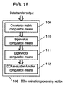
- Fig.16 is a block diagram of a conventional DOA processing section 108.
- the T indicates transposition, and the H exhibits complex conjugate transposition.
- X(k) [x 1 (k), x 2 (k), ---,x M (k)]
- An eigenvalue computation means 110 gets eigenvalues ⁇ 1,---, ⁇ M by computing the eigenvalues of the covariance matrix R in descending order.
- An eigenvector computation means 111 computes eigenvectors e 1 ---,e M corresponding to the eigenvalues ⁇ 1,---, ⁇ M.
- a number of arriving waves is S
- the DOA estimation function F( ⁇ ) is defined as formula 4, that evaluates an orthogonal characteristics with E N at the time when ⁇ is rotated from 0 to 360° , wherein a( ⁇ ) (steering vector) indicates complex response of an array antenna against the direction ⁇ .
- a( ⁇ ) steering vector
- the purpose of the present invention is to simplify the composition of the DOA estimation apparatus, and to provide an apparatus that enables to decrease the transfer speed of a data transfer section to signal processing apparatus and at the same time to decrease the memory capacity for accumulation and to alleviate the computation capacity of signal processing apparatus by decreasing the amount of computation.
- the present invention is to provide an DOA estimation apparatus to detect accurately an DOA of the maximum level among multiple waves, even when the number of antenna elements is small and the correlation between the arriving waves is high.
- the present invention is to provide a variable directional signal receiving apparatus that improves receiving quality by controlling directivity of an antenna.
- the another purpose of the present invention is to provide the DOA estimation apparatus that can estimate a direction of a main wave accurately even with a simple array composition like four elements or so and under multiple wave environment where correlation waves exist.
- Still another purpose of the present invention is to provide a variable directional signal receiving apparatus, a variable directional signal transmitting apparatus and a variable directional signal receiving and transmitting apparatus that improves receiving and transmitting quality by controlling directivity of an antenna, utilizing a result of estimation by the DOA estimation apparatus.
- the DOA estimation apparatus of the present invention comprises:
- variable directional signal receiving apparatus of the present invention improves the receiving quality of receiving apparatus by controlling directivity of antenna based on the aforesaid output data from the data transfer section.
- composition of the DOA estimation apparatus of the present invention comprises:
- the deterioration of the accuracy of the DOA estimation can be suppressed at minimum level by combining the power estimation even when there is a highly correlated wave among the arrival waves.
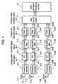
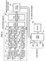
- Fig. 1 is a block diagram of a DOA estimation apparatus of the present invention.
- the signals 2-1,---,2-M received by antenna elements 1-1,---,1-M, where M is a number of elements (M >1), are convened at frequency converters 3-1,---,3-M connected to each antenna elements 1-1,---,1-M and the signals are phase detected and then are convened to complex base band signals 4-1,---,4-M composed of onhogonal I, Q signals.
- the respective complex base band signals are converted from analog signals to complex digital signals 6-1,---,6-M by A/D conveners 5-1,---,5-M.
- the sampling frequency fs of the A/D convener 5-1,---,5-M here is to satisfy the sampling theorem, that is to have the relation against the band width of transmitting modulation wave WB(Hz) as fs ⁇ 2WB.
- Low pass filters 7-1,---,7-M attenuates a high frequency component of 6-1,---,6-M and outputs complex low band signals 8-1,---,8-M smoothed time-wise.
- the data transfer section 11 transfers x 1 (k), x 2 (k), ---,x M (k) obtained from the complex down sampled signals 10-1,---,10-M. to a direction estimation processing section 12.
- the (k) here indicates down sample time k x Nd x ⁇ T .
- the direction estimation processing section 12 performs direction estimation using the output data from the data transfer section 11 by performing computation based on the MUSIC method.
- the contents of the direction estimation processing section 12 has the same composition with the direction estimation process section 108 in Fig. 15 and performs the same processing.
- composition of the present invention it is different from the conventional apparatus in outputting a complex low band signals 8-1,---,8-M attenuated a high frequency component of the complex digital signal with the low pass filter 7-1,---,7-M and smoothed time-wise.
- Another difference with the conventional apparatus is to make down sampling of the complex digital signal at every Nd samples in the down samplers 9-1,---,9-M. Namely, since the complex down sampled signals 9-1,---,9-M become N/Nd against the sample number N of the complex digital signal 6-1,---,6-M, the computation of the covariance matrix computation means 109 at the direction estimation processing section 108 is shown as formula 5, while it is shown conventionally as formula 2.
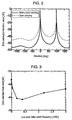
- Fig. 2 is a chart comparing a processing result of the direction estimation process section 12 with a result of the conventional MUSIC method by a computer simulation.
- Fig. 2 shows an estimation result in the case that two waves arrive from the direction of 0° and 100° to a four- elements circular array antenna. The result is respectively normarized by the maximum value.
- the data amount of the complex digital signal 6-1,---,6-M is suppressed 1/100 by down sampler section 9. Even though the peak value of the DOA evaluate function value is decreased by the down sampling, the direction of the peak matches within the aberration 1 degree, and it can be confirmed that the accuracy is not much deteriorated.
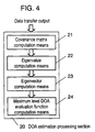
- the fc is a carrier frequency of a wave of which DOA is to be estimated. The effect of improvement can be obtained by optimizing the cut off frequency f of the low pass filter 7 within the 10 - 50% of 3 dB band width W.
- the deterioration of the direction estimation accuracy can be suppressed at the minimum level and the amount of data processed at the estimation processing section can be decreased by down sampling the complex digital signal 6 at the down sampler section 9 after passing through the low pass filter 7.
- the cost of the data transfer section 11 can be lowered,
- the amount of computation in the covariance matrix means 109 at the direction estimation processing section 12 can be decreased.
- the required computation processing capability can be decreased and the cost of the direction estimation processing section 12 can be lowered.
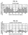
- the direction estimation processing section 20 of the block diagram in Fig.4 is used, in place of the direction estimation processing section 12 in Fig.1.
- the description of the output of the data transfer section 11 is omitted here, since the description is the same as in the first exemplary embodiment described in Fig.1.
- the operation of direction estimation process section 20 will now be described.
- a covariance matrix computation means 21 computes a covariance matrix R using the receiving vector from X(1) to X(Ns) storing Ns numbers of complex down sampled signals 10 down sampled at the down samplers 9.
- the H indicates complex conjugate transposition.
- X(k) [x 1 (k), x 2 (k), ---,x M (k)]
- a eigenvalue computation means 22 computes an eigenvalue ⁇ 1,---, ⁇ M by computing the eigenvalue of the covariance matrix R in descending order
- An eigenvector computation means 43 computes an eigenvector e 1 ,---,e M corresponding to the eigenvalue ⁇ 1,---, ⁇ M.
- a direction of an arrival wave is estimated by performing a peak search based on a result of the DOA evaluate function F( ⁇ ) at the time when an angle ⁇ is rotated from 0 to 360°.
- Fig.5A,B show results of the DOA estimation simulation conducted with a four elements circular array antenna by the MUSIC method (Fig.5 A ) and the present exemplary embodiment (Fig.5 B) respectively.
- the condition for the simulation is as follows.
- the arriving angle of the first wave is 0° with the signal level is 0dB and signal level of the second wave is -3dB and the arriving angle is to be rotated from -180 degrees to 180 degrees with 10 degrees interval.
- the sampling frequency fs of the A/D converter 5 is 4 times of the symbol frequency f symbol , and down sampling is fs/100.
- the direction of the arrival wave with the maximum level among the plurality of arriving waves can be estimated accurately by having the maximum level DOA evaluate function computation means 24 in the direction estimation processing section 20.
- the direction of the arrival wave with the maximum level among the plurality of arriving waves can be estimated accurately even in the case when the number of elements of antenna are small and the correlation between the arrival waves is high , by limiting the application of estimation not for all the plurality of arrival waves but for the maximum level arrival wave among the plurality of arrival waves.
- variable directional signal receiving apparatus of which directivity is variable by selecting the plurality of sector antenna will now be described.
- the variable directional signal receiving apparatus of the present exemplary embodiment is effective for improving the receiving quality.
- Fig.6 is a block diagram of a variable directional signal receiving apparatus.
- the variable directional signal receiving apparatus comprises a DOA estimation apparatus having a function of direction estimation processing section shown in the second exemplary embodiment , m pieces (m ⁇ 2) of sector antennas 30-1,---,30-m having different main beam directions, a sector switch 31, a sector controller 32 and a receiver 33.
- the sector controller 32 selects the number ms sector antenna of which main bean direction is the closest direction of the maximum level wave among the plurality of sector antennas from 30-1 to 30-M based on the estimation result, and controls the sector switch 31 to be connected to the receiver 33.
- the sector switch 31 connects the number ms sector antenna to the receiver 33 based on the sector control signal 34.
- the receiver 33 performs demodulation operation to the receiving signal from the connected number ms sector antenna.
- the most appropriate sector antenna of which main bean direction is the closest direction of the maximum level wave can be selected among the plurality of sector antennas 30-1,---,30-M and the receiving signal with high S/N ratio can be obtained. Also, the multiple beams other than the main beam direction of the selected sector antenna is suppressed and the interference between the signals can be decreased.
- the same effect can be achieved with the composition that the main beam direction is to be matched with the maximum level direction estimation result at the DOA estimation process section 20 by performing the phase control of the plurality of antenna elements 1-1,---,1-M with the phase control signal from the sector control section 32 by installing a phase control section, which is not shown in Fig.6, in place of the sector switch 31.
- the deterioration of the direction estimation accuracy can be suppressed to the minimum level
- the amount of data processed at the estimation processing section can be decreased by the down sampling the complex digital signals after passing through the low pass filter, required amount of memory for accumulation can be decreased and also the data transfer speed can be decreased.
- the direction of the arrival wave with the maximum level among the plurality of arrival waves can be estimated accurately even in the case when the numbers of the antenna elements is small and the correlation between the arrival waves is high, by limiting the application of estimation not for all the arrival waves but for the maximum level arrival wave among the plurality of arrival waves.
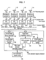
- Fig.7 is a block diagram of the DOA estimation apparatus of the present invention.
- the direction estimation section 12 of Fig.1 is applicable.
- the operation will now be described.
- the antennas 1-1,---,1-M, where M is the number of elements (M >1), are placed in a circular shape array having the elements in the identical intervals with radius r.
- M the number of elements
- the receiving signals 2-1,---,2-M received by the respective antenna elements 1-1,---,1-4 (1-M in general, hereinafter shown as a general example) are frequency converted at the frequency converters 3-1,---,3-M connected to respective antenna elements 1-1,---,1-4 and, after being through the quadrature demodulation, converted to the complex base band signals 4-1,---,4-M composed of orthogonal I, Q signals.
- Respective complex base band signals 4-1,---,4-M are converted from analog signals to complex digital signals 6-1,---,6-M by A/D) converters 5-1,---,5-M.
- the sampling frequency fs of the A/D converters 5-1,---,5-M here is not required to be sampled with a nyquist condition as fs ⁇ 2WB against the band width of transmitting modulation wave W B (Hz) since modulation operation is not taken place in the following processing, but the jitter of sampling is required to be small enough so that sufficient accuracy of the DOA estimation can be obtained.
- the ⁇ T indicates a sampling interval.
- the T exhibits transposition
- the H exhibits complex conjugate transposition.
- X(k) [x 1 (k), x 2 (k), ---,x M (k) ]
- the eigenvalue computation section 39 makes the eigenvalue ⁇ 1,---, ⁇ M by computing the eigenvalue of the covariance matrix R in descending order and then computes the eigenvector e 1 ,---,e M corresponding to the eigenvalue ⁇ 1,---, ⁇ M.
- the numbers of arriving waves in the case of Er ⁇ Dr, is judged as 1 regarding the number of arrival wave is one or plural, and in the case of Er ⁇ Dr, the numbers of arrival waves is judged as M-1.
- the false peak can be eliminated by synthesizing with a power estimation result at the arrival wave power estimation section 43.
- the DOA evaluation function F(6) is defined as formula 7, that evaluates an orthogonal characteristics between a signal subspace Es and a noise subspace En.
- a( ⁇ ) is a steering vector which is a complex response of array antenna against direction ⁇ and outputs the result of computation of F( ⁇ ) at the time when angle ⁇ is varied from 0 to 360 degrees with the specified angle interval ⁇ .
- F( ⁇ ) [a H ( ⁇ ) E N E N H a ( ⁇ )] -1
- a virtual linear array converter 42 converts signals 2-1,---,2-M received by a circular array to received signals by a virtual linear array.
- the conversion method to a virtual linear array is described in the paper of M.Wax et al, "Direction Finding of Coherent Signals via Spatial Smoothing for Uniform Circular Arrays", IEEE Trans. AP-42, No.5, 1994. The detailed explanation of the paper is omitted here.
- h indicates natural number.
- a conversion matrix to a virtual linear array is expressed with a matrix product JF of matrix F of formula 8 and matrix J of formula 9.
- Jn indicates vessel function of n order
- k 2 ⁇ / ⁇
- ⁇ indicates a wave length of carrier wave
- r indicates the radius of uniform circular array.
- J diag ⁇ 1 ⁇ Mj m J m (kr) ⁇
- m -h, ... , 0, ... ,h
- the receiving vector xv(k) of a virtual liner array is computed as the product of conversion matrix JF and the receiving vector x(k) of a circular array arranged uniformed interval.
- Xv(k) JFx(k)
- the arrival wave power estimation section 43 performs a computation as follows based on the information shown in the paper of R.O.Schmidt, "Multiple emitter Location and Signal parameter Estimation", IEEE Trans., AP-34, 3, pp.276-280 (1986).
- a covariance matrix Rv of a receiving vector xv(k) from a virtual linear array is computed with formula 11.
- an arrival wave power estimation is conducted with (formula 12) using a specified angle interval ⁇ .
- the ⁇ 2 indicates a noise power and corresponds to the minimum eigenvalue.
- the main wave direction estimation section 44 computes a synthesized value Ps( ⁇ ) from the computed value F( ⁇ ) at the DOA estimation section 41 as shown in formula 7 and the computed value P( ⁇ ) at the arriving wave power estimation section 43 as shown in formula 12, and estimates the direction of the maximum level by detecting the maximum value wave direction and then outputs the result of DOA estimation result 15 (formula 13).
- the ⁇ here indicates a constant parameter for weighting.
- Ps( ⁇ ) F( ⁇ ) + ⁇ P ( ⁇ )
- the estimation tends to be influenced, in general, with grating due to the symmetric arrangement when space spectrum is estimated.
- the estimation accuracy can be improved by eliminating the above influence by using the power estimation using the virtual linear array in accordance with the present composition.
- a conventional DOA estimation by eigenvalue decomposition such as the MUSIC method
- the separation of the number of arrival wave can not be estimated accurately because the correlation of arrival waves is high under the multiple wave transmission environment where multiple waves are composed from the reflection of the earth or buildings and when the reciprocal delay time is within a symbol time or so.
- the present exemplary embodiment using a complex digital signal, it becomes possible to decrease the estimation error by synthesizing the both estimation results of the power estimation and of the DOA estimation, even when the estimation of the arrival wave number is wrong.
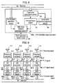
- the same effect can be obtained with the composition of the DOA estimation signal processor 38a as shown in Fig.8.
- the difference from the Fig.7 is that the virtual linear array converter 12 is not required since the array is arranged linearly, the arrival wave power estimation section 43 performs the power estimation directly against the complex signals 6-1,---,6-M obtained through data bus 37. The other operation is the same with the case in Fig.7.
- the A/D conversion is processed for the complex base band signals 4-1,---,4-M
- the A/D conversion can be processed for the IF signals 4a-1,---,4a-M which is converted from the receiving signals 2-1,---,2-M received at antenna elements 1-1,---,1-M to the intermediate frequency(IF) at the frequency converters 3-1,---,3-M.
- the same effect can be obtained with the composition that the complex digital signals 6-1,---,6-M are formed with the process that the obtained IF digital signals 6a-1,---,6a-M are processed through digital quadrature demodulation at digital quadrature detection section.
- the A/D converters 5a-1,---,5a-M also, performs the nyquist sampling or bandpass sampling against the received IF signals 4a-1,---,4a-M.
- the stages after IF stage can be digitalized and becomes preferable for the integration.
- Fig. 10 is block diagram of another DOA estimation signal processor 38b.
- the difference with the fourth exemplary embodiment will be described mainly next.
- the difference with the DOA estimation processor Fig.7 are the SN ratio computation section 50 that computes SN ratio of the complex digital signals 6-1,---,6-M and it changes the specified value for the arrival wave number judgement section 51 by the computed SN ratio. The operation will be described next.
- the SN computation section 40 computes a SN ratio with formula 14 using receiving signal vector (k) shown in formula 5 from the complex digital signals 6-1,---,6-M obtained through data bus.
- N 0 indicates a noise power level computed with formula 15 using receiving vector x0 (k) obtained from the receiving signals 2-1,---,2-M when no transmitting signal is received.
- SN x(k) H x(k)/N o +1
- N0 x o (k) H x o (k)
- the judgement of arrival wave number at the arrival wave number judgement section 51 can be conducted in stable condition without being influenced by the receiving level of the arrival wave.
- Fig. 11 is a block diagram showing yet another composition of a DOA estimation signal processor 38a. The difference with the fourth exemplary embodiment will be described mainly next.
- the DOA estimation signal processor 38c is equipped with a SN ratio computation section 50 that computes SN ratio of the complex digital signals 6-1,---,6-M, a dynamic range memory 60 that outputs a corresponding memorized dynamic range value of the DOA estimation based on the computed SN ratio, a dynamic range computation section 61 that computes the dynamic range of the DOA estimation section 41, and the arrival wave number judgement section 62 that judges the number of arriving wave based on the output from the dynamic range memory 60 and the dynamic range computation section 61.
- SN ratio computation section 50 that computes SN ratio of the complex digital signals 6-1,---,6-M
- a dynamic range memory 60 that outputs a corresponding memorized dynamic range value of the DOA estimation based on the computed SN ratio
- a dynamic range computation section 61 that computes the dynamic range of the DOA estimation section 41
- the arrival wave number judgement section 62 that judges the number of arriving wave based on the output from the dynamic range memory 60 and the dynamic range computation section 61.
- the SN computing section 50 computes a SN ratio with formula 14 using receiving signal vector (k) shown in formula 5 from the complex digital signals 6-1,---,6-M obtained through data bus.
- N 0 indicates a noise power level computed with formula 15 using receiving vector x 0 (k) obtained from the receiving signals 2-1,---,2-M when no transmitting signal is received.
- the dynamic range memory 60 memorizes the DM that is the dynamic range value computed from the SN ratio at the SN ratio computing section 50 and the DOA estimation result at the DOA estimation section 41.
- the DM is obtained, in advance, from the result of a preliminary transmitting experiment for DOA estimation that is conducted in a wave dark room by generating plurality of waves (less than M-1) which has no reciprocal correlation with each other.
- the arrival wave number judgement section 62 judges the number of arrival wave based on the output from the dynamic range memory 60 and the dynamic range computation section 61.
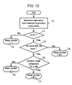
- Fig. 12 is the flow chart of the arrival wave number judgement section 62.
- the arrival wave number judgement section 62 compares Er with the specified value Dr (Step 71).
- the arrival wave number judgement section 62 judges the number of arriving wave is as 1 if Er ⁇ Dr (Step 72).
- the arriving wave number judgement section 62 compares the computed dynamic range value DS and the memorized value DM (Step 75), if DS ⁇ DM, it judges the number of wave as 1 judging correlation wave is included (Step 76). If DS ⁇ DM, the arriving wave number judgement section 62 judges the number of arrival wave as M-1 judging that there is no correlation among the arrival waves (Step 77).
- the judgement value at the arriving wave number judgement section 62 can be varied based on the correlation among the arrival waves utilizing the estimation result at the DOA estimation section 41 of which dynamic range becomes small when the correlation among the arrival wave is high even with the same SN ratio. As the result, the DOA estimation can be conducted in stable condition even under the various transmission conditions.
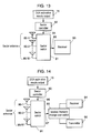
- Fig. 13 is a block diagram of a variable directional signal receiving apparatus.
- the variable directional signal receiving apparatus of the present exemplary embodiment is characterized by the usage of the DOA estimation process section 38,---,38c that estimates the direction of the maximum level as explained in the fourth through sixth exemplary embodiment.
- the variable directional signal receiving apparatus makes the directivity of the receiver variable by selecting the plurality of sector antennas that have different main beam directions. The selection is based on the DOA estimation results 15 from the DOA estimation processing section.
- the further explanation of the operation of the DOA estimation processing section is omitted here, since it is the same with that explained in the fourth through sixth exemplary embodiment. With reference to Fig. 13, the additional section will be described next.
- the variable directional signal receiving apparatus of the present exemplary embodiment comprises m (m ⁇ 2) pieces of sector antennas 80-1,---,80-M having different main beam direction, a sector switch 81, a sector controller 82 and a receiver 83.
- the operation at Fig. 13 will be described next.
- the operation to estimate the DOA using the receiving signal obtained from the array antenna is the same with that is explained in the fourth through sixth exemplary embodiment.
- the final result of the maximum level direction estimation 15 obtained at DOA estimation signal processor is input to the sector controller 82.
- the sector controller 82 selects the number m s sector antenna of which main bean direction is the closest direction of the maximum level among the plurality of sector antennas 80-1,---,80-m based on the estimation result and controls the sector switch 81 to be connected to the receiver 83.
- the sector switch 81 connects the number m s sector antenna to the receiver 83 based on the sector control signal 84.
- the receiver 83 conducts demodulation of the receiving signal 85 from the connected number m s sector antenna.
- the most appropriate sector antenna of which main bean direction is the closest direction of the maximum level can be selected among the plurality of sector antennas and the receiving signal 85 with high S/N ratio can be obtained. Also, the multiple beams other than the main beam direction of the selected sector antenna are suppressed and the interference between the signals can be decreased.
- the sector antenna of which main bean direction is the closest direction with the maximum level direction estimation result at the DOA signal processor is selected. But the same effect can be achieved with the composition that the main beam direction is to be matched with the maximum level direction estimation result at the DOA estimation signal processor by performing the phase control of the plurality of antenna elements.
- the composition of receiving apparatus is shown. It can also be applied for a transmitting apparatus by replacing the receiver 83 to transmitter and by connecting the output of the transmitter to the sector switch 81. According to this composition, the high quality transmission can be achieved with the transmission by selecting the most appropriate sector antenna of which main bean direction is the closest direction of the maximum level of the arrival wave without transmitting the power to the unnecessary directions.
- Fig.14 is a block diagram of a variable directional signal receiving and transmitting apparatus.
- the variable directional signal receiving apparatus of the present exemplary embodiment is, as explained in the fourth through sixth exemplary embodiment, using the DOA estimation processing section that estimates the direction of the maximum level. It selects the plurality of sector antenna that have different main beam direction based on the output of the DOA estimation results 15, making the directivity variable.
- the further explanation of the operation of the DOA estimation process section is omitted here since it is aforementioned. With reference to Fig. 14, the additional section will be described next.
- the variable directional signal receiving and transmitting apparatus in Fig.14 comprises m (m ⁇ 2) pieces of sector antennas 90-1,---,90-M having different main beam direction, a sector switch 91, a sector controller 92, a receive/transmit changeover switch 93, receiver 94, and a transmitter 95.
- the operation at Fig. 14 will be described next.
- the operation to estimate the DOA using the receiving signal obtained from the array antennas is the same with that is explained in the fourth through sixth exemplary embodiment.
- the final result of the maximum level direction estimation 15 obtained at the DOA estimation signal processor is input to the sector controller 92.
- the sector controller 92 selects the number m s sector antenna of which main bean direction is the closest direction of the maximum level among the plurality of sector antennas 90-1,---,90-M based on the estimation result and controls the sector switch 91 to be connected to the receive/transmit changeover switch 93.
- the sector switch 91 connects the number m s sector antenna to the receive/transmit changeover switch 93 based on the sector control signal 96.
- the receiver 94 conducts demodulation of the receiving signal 97 from the connected number m s sector antenna.
- the transmitter 95 transmits the transmitting signal through the number m s sector antenna
- the receiving and transmitting can be performed by the most appropriate sector antenna of which main bean direction is the closest direction of the maximum level selected among the plurality of sector antenna, and also the multiple beams other than the main beam direction of the selected sector antenna is suppressed and the interference between the signals can be decreased.
- the sector antenna of which main bean direction is the closest direction with the maximum level direction estimation result at the DOA estimation signal processor is selected. But the same effect can be achieved with the composition that the main beam direction is to be matched with the maximum level direction estimation result at the DOA estimation signal processor by performing the phase control of the plurality of antenna elements.
- the estimation accuracy can be improved by eliminating the influence of grating which occurs when the power is estimated with the circular array antenna.
- the separation of the number of arriving wave can not be estimated accurately because the correlation of arriving waves is high under the multiple wave transmission environment where multiple waves are composed from the reflection of the earth or buildings and when the reciprocal delay time is within a symbol time or so.
Landscapes
- Physics & Mathematics (AREA)
- Engineering & Computer Science (AREA)
- General Physics & Mathematics (AREA)
- Radar, Positioning & Navigation (AREA)
- Remote Sensing (AREA)
- Radio Transmission System (AREA)
- Variable-Direction Aerials And Aerial Arrays (AREA)
Abstract
Description

Claims (21)
- A direction of arrival (hereinafter recited as DOA) estimation apparatus comprising:an array antenna using a plurality of antenna elements;a plurality of frequency converters that frequency convert and phase detect respective high frequency signals obtained from respective antenna elements of said array antenna and output a complex base band signals;a plurality of A/D converters that converts a plurality of complex base band signals output from said plurality of frequency converters to respective complex digital signals;a plurality of low pass filters that output respective complex low frequency signals with attenuated high frequency components of complex digital signals converted by said plurality of A/D converters;a plurality of down samplers that output complex signals respectively, said complex signals are down sampled by down sampling and multiplied by integral number of sampling interval of said A/D converter, said complex low pass signal generated from said plurality of low pass filters;a data transfer section that accumulates said plurality of complex down sampled signals obtained from respective said antenna elements and transfers the data; anda DOA estimation processing section that estimates an arrival direction of wave based on data output from of said data transfer section.
- The DOA estimation apparatus according to claim 1, wherein a band width of said low pass filter ranges within the 10-50% of 3dB band width of an arriving wave of estimating DOA.
- The DOA estimation apparatus according to claim 1 and 2, wherein said direction estimation processing section comprises:a covariance matrix computation means to compute a covariance matrix using a plurality of complex down sampled signals obtained from respective antenna elements of said array antenna;an eigenvalue computation means to compute an eigenvalue from said covariance matrix;an eigenvector computation means to compute a eigenvector corresponding to said eigenvalue; anda DOA estimation function computation means using an eigenvector obtained by said eigenvector computation means.
- The DOA estimation apparatus according to claim 3 , wherein said DOA estimation function computation means is a maximum level direction estimation function computation means that estimates a direction of the maximum level of an arrival wave by computing a DOA evaluation function appreciating an orthogonal characteristics of the eigenvector, corresponding to an eigenvalue except the maximum value among the eigenvector.
- A variable directional receiving apparatus comprising:(1) a direction of arrival (DOA) estimation apparatus comprising:an array antenna using a plurality of antenna elements;a plurality of frequency converters that frequency convert and phase detect respective high frequency signals obtained from respective antenna elements of said array antenna and output a complex base band signals;a plurality of A/D converters that converts a plurality of complex base band signals output from said plurality of frequency converters to respective complex digital signals;a plurality of low pass filters that output respective complex low frequency signals with attenuated high frequency components of complex digital signals converted by said plurality of A/D converters;a plurality of down samplers that output complex signals respectively, said complex signals are down sampled by down sampling and multiplied by integral number of sampling interval of said A/D converter, said complex low pass signal generated from said plurality of low pass filters;a data transfer section that accumulates said plurality of complex down sampled signals obtained from respective said antenna elements and transfers the data; anda DOA estimation processing section that estimates an arrival direction of wave based on data output from of said data transfer section.
wherein said DOA estimation processing section comprises:a covariance matrix computation means to compute a covariance matrix using a plurality of complex down sampled signals obtained from respective antenna elements of said array antenna;an eigenvalue computation means to compute an eigenvalue from said covariance matrix;an eigenvector computation means to compute a eigenvector corresponding to said eigenvalue; anda DOA estimation function computation means using an eigenvector obtained by said eigenvector computation means.(2) a plurality of sector antennas designed to have different main beam direction;(3) a sector control section to output a sector control signal to select one sector antenna from said plurality of sector antennas based on the computation result by a maximum level DOA evaluation function computation means of said DOA estimation apparatus;(4) a sector switch that connects said sector antenna selectively based on a sector control signal output from said sector control section; anda receiver. - A variable directional receiving apparatus comprising:(1) a direction of arrival (DOA) estimation apparatus comprising:an array antenna using a plurality of antenna elements;a plurality of frequency converters that frequency convert and phase detect respective high frequency signals obtained from respective antenna elements of said array antenna and output a complex base band signals;a plurality of A/D converters that converts a plurality of complex base band signals output from said plurality of frequency converters to respective complex digital signals;a plurality of low pass filters that output respective complex low frequency signals with attenuated high frequency components of complex digital signals converted by said plurality of A/D converters;a plurality of down samplers that output complex signals respectively, said complex signals are down sampled by down sampling and multiplied by integral number of sampling interval of said A/D converter, said complex low pass signal generated from said plurality of low pass filters;a data transfer section that accumulates said plurality of complex down sampled signals obtained from respective said antenna elements and transfers the data; anda DOA estimation processing section that estimates an arrival direction of wave based on data output from of said data transfer section.
wherein said DOA estimation processing section comprises:a covariance matrix computation means to compute a covariance matrix using a plurality of complex down sampled signals obtained from respective antenna elements of said array antenna;an eigenvalue computation means to compute an eigenvalue from said covariance matrix;an eigenvector computation means to compute a eigenvector corresponding to said eigenvalue; anda DOA estimation function computation means using an eigenvector obtained by said eigenvector computation means.(2) a plurality of sector antennas designed to have different main beam direction;(3) a phase controller that performs a phase control of an output of said plurality of antenna elements based on the computation result by the maximum level DOA evaluation function computation means of said DOA estimation apparatus; and(4) a receiver to take corresponding demodulation operation against the output signal from said phase control section. - A direction of arrival (DOA) estimation apparatus comprising:an array antenna comprising a plurality of antenna elements placed with uniformed intervals as a circular shape array ;a plurality of frequency converters that frequency convert and phase detect respective high frequency signals obtained from respective antenna elements of said array antenna and output a complex base band signals;a plurality of A/D converters that converts a plurality of complex base band signals output from said plurality of frequency converters to respective complex digital signals;a virtual linear array converter that converts said complex digital signals output from said A/D converters at specified interval time to a virtual linear array receiving signals;an arrival wave power estimation section that estimates a power of the arriving wave from the output of said virtual linear array converter;an eigenvalue computation section that performs a correlation matrix computation against said complex digital signals sampled at said specified interval time and computes an eigenvalue and an eigenvector;an arrival wave judgement section that judges a number of arrival wave from the eigenvalue computed at said eigenvalue computation section;a DOA estimation section that changes a condition of arrival wave estimation processing by a eigenvalue decomposition method based on a judging result of said arrival wave judgement section; anda main wave direction estimation section that estimates a direction of a wave with a maximum level by synthesizing the estimation results at said arrival wave power estimation section and results at said DOA estimation section.
- A direction of arrival (DOA) estimation apparatus comprising:an array antenna comprising a plurality of antenna elements placed with uniformed intervals as a circular shape array ;a plurality of frequency converters that frequency convert and phase detect respective high frequency signals obtained from respective antenna elements of said array antenna and output a complex base band signals;a plurality of A/D converters that converts a plurality of complex base band signals output from said plurality of frequency converters to respective complex digital signals;an arrival wave power estimation section that estimates an power of the arrival wave from said complex digital signals sampled at specified interval time from said A/D converter;an eigenvalue computation section that performs a correlation matrix computation against said complex digital signals sampled at said specified interval time and computes an eigenvalue and an eigenvector;an arrival wave judgement section that judges a number of arrival wave from the eigenvalue computed at said eigenvalue computation section;a DOA estimation section that changes a condition of arrival wave estimation processing by a eigenvalue decomposition method based on a judging result of said arrival wave judgement section; anda main wave direction estimation section that estimates a direction of a wave with a maximum level by synthesizing the estimation results at said arrival wave power estimation section and results at said DOA estimation section.
- The DOA estimation apparatus according to claim 7 or 8, wherein said arrival wave number judgement section judges a number of arrival wave based on a ratio between a maximum eigenvalue and a next largest eigenvalue among the computed eigenvalue at said eigenvalue computation section.
- The DOA estimation apparatus according to claim 7 or 8, wherein said arrival wave number judgement section judges a number of arrival wave as "1" if a ratio between a maximum eigenvalue and a next largest eigenvalue is larger than predetermined value, and judges a number of arrival wave as " number of antenna elements - 1" if the ratio between a maximum eigenvalue and a next largest eigenvalue is smaller than predetermined value
- The DOA estimation apparatus according to claim 7 or 8 , wherein said DOA estimation section performs the arrival direction estimation by computing the DOA evaluation function, and said main wave direction estimation section decides the peak direction as the maximum level of arriving wave by adding the estimation results of said arrival wave power estimation section and estimation results of said arrival wave direction estimation section.
- The DOA estimation apparatus according to claim 7 or 8, wherein said main wave direction estimation section decides the peak direction as the maximum level of arrival wave by adding with weighting the estimation results of said power estimation section and the estimation results of said arrival direction estimation section.
- The DOA estimation apparatus according to claim 7 or 8 , further comprising:a signal to noise (SN) ratio computation section that computes SN ratio from the output of said A/D converters and if SN ratio is less than a specified value, said arrival wave number judgement section judges a number of arrival wave as 1.
- The DOA estimation apparatus according to claim 7 or 8, further comprising:a signal to noise (SN) ratio computation section that computes SN ratio from the output of said A/D converters; anda dynamic range memory that memorizes a dynamic range of the DOA evaluation function from said DOA estimation section in advance against a hypothetical SN ratio value,
wherein said arriving wave number judgement section computes the DOA evaluate function and obtains a dynamic range by subtracting a minimum value from a maximum value, compares said dynamic range with a memorized dynamic range value stored at said dynamic range memory and judges the number of arrival wave as 1 if said dynamic range is smaller than the memorized value. - The DOA estimation apparatus according to claim 7 or 8, further comprising:digital quadrature detectors that perform digital quadrature demodulation for the digital signals from said A/D converters and outputs a complex base band signals to a virtual linear array converter and to the eigenvalue computation section,
wherein said frequency converters output an intermediate frequency (IF) signals by frequency conversion and phase detection with the high frequency obtained from an respective antenna elements, and said A/D converters convert said IF signals output from said frequency converters to digital signals. - A variable directional signal receiving apparatus comprising:(1) a direction of arrival (DOA) estimation apparatus comprising;an array antenna comprising a plurality of antenna elements placed with uniformed intervals as a circular shape array ;a plurality of frequency converters that frequency convert and phase detect respective high frequency signals obtained from respective antenna elements of said array antenna and output a complex base band signals;a plurality of A/D converters that converts a plurality of complex base band signals output from said plurality of frequency converters to respective complex digital signals;a virtual linear array converter that converts said complex digital signals output from said A/D converters at specified interval time to a virtual linear array receiving signals;an arrival wave power estimation section that estimates a power of the arriving wave from the output of said virtual linear array converter;an eigenvalue computation section that performs a correlation matrix computation against said complex digital signals sampled at said specified interval time and computes an eigenvalue and an eigenvector;an arrival wave number judgement section that judges a number of arrival wave from the eigenvalue computed at said eigenvalue computation section;a DOA estimation section that changes a condition of arrival wave estimation processing by a eigenvalue decomposition method based on a judging result of said arrival wave judgement section; anda main wave direction estimation section that estimates a direction of a wave with a maximum level by synthesizing the estimation results at said arrival wave power estimation section and results at said DOA estimation section.(2) plurality of sector antennas designed to have different main beam direction;(3) a sector control section that outputs a sector control signal to select one sector antenna from said plurality of sector antennas based on the estimation result of a main wave direction estimation section of said DOA estimation apparatus;(4) a sector switch that connects said sector antenna selectively based on the sector control signal output from said sector control section; and(5) a receiver.
- A variable directional signal receiving apparatus comprising:(1) a direction of arrival (DOA) estimation apparatus comprising;an array antenna comprising a plurality of antenna elements placed with uniformed intervals as a circular shape array ;a plurality of frequency converters that frequency convert and phase detect respective high frequency signals obtained from respective antenna elements of said array antenna and output a complex base band signals;a plurality of A/D converters that converts a plurality of complex base band signals output from said plurality of frequency converters to respective complex digital signals;an arrival wave power estimation section that estimates an power of the arrival wave from said complex digital signals sampled at specified interval time from said A/D converter;an eigenvalue computation section that performs a correlation matrix computation against said complex digital signals sampled at said specified interval time and computes an eigenvalue and an eigenvector;an arrival wave number judgement section that judges a number of arrival wave from the eigenvalue computed at said eigenvalue computation section;a DOA estimation section that changes a condition of arrival wave estimation processing by a eigenvalue decomposition method based on a judging result of said arrival wave judgement section; anda main wave direction estimation section that estimates a direction of a wave with a maximum level by synthesizing the estimation results at said arrival wave power estimation section and results at said DOA estimation section.(2) plurality of sector antennas designed to have different main beam direction;(3) a sector control section that outputs a sector control signal to select one sector antenna from said plurality of sector antennas based on the estimation result of a main wave direction estimation section of said DOA estimation apparatus;(4) a sector switch that connects said sector antenna selectively based on the sector control signal output from said sector control section; and(5) a receiver.
- A variable directional signal transmitting apparatus comprising:(1) a direction of arrival (DOA) estimation apparatus comprising;an array antenna comprising a plurality of antenna elements placed with uniformed intervals as a circular shape array ;a plurality of frequency converters that frequency convert and phase detect respective high frequency signals obtained from respective antenna elements of said array antenna and output a complex base band signals;a plurality of A/D converters that converts a plurality of complex base band signals output from said plurality of frequency converters to respective complex digital signals;a virtual linear array converter that converts said complex digital signals output from said A/D converters at specified interval time to a virtual linear array receiving signals;an arrival wave power estimation section that estimates a power of the arriving wave from the output of said virtual linear array converter;an eigenvalue computation section that performs a correlation matrix computation against said complex digital signals sampled at said specified interval time and computes an eigenvalue and an eigenvector;an arrival wave number judgement section that judges a number of arrival wave from the eigenvalue computed at said eigenvalue computation section;a DOA estimation section that changes a condition of arrival wave estimation processing by a eigenvalue decomposition method based on a judging result of said arrival wave judgement section; anda main wave direction estimation section that estimates a direction of a wave with a maximum level by synthesizing the estimation results at said arrival wave power estimation section and results at said DOA estimation section.(2) plurality of sector antennas designed to have different main beam direction;(3) a sector control section that outputs a sector control signal to select one sector antenna from said plurality of sector antennas based on the estimation result of a main wave direction estimation section of said DOA estimation apparatus;(4) a sector switch that connects said sector antenna selectively based on the sector control signal output from said sector control section; and(5) a transmitter.
- A variable directional signal transmitting apparatus comprising:(1) a direction of arrival (DOA) estimation apparatus comprising;an array antenna comprising a plurality of antenna elements placed with uniformed intervals as a circular shape array ;a plurality of frequency converters that frequency convert and phase detect respective high frequency signals obtained from respective antenna elements of said array antenna and output a complex base band signals;a plurality of A/D converters that converts a plurality of complex base band signals output from said plurality of frequency converters to respective complex digital signals;an arrival wave power estimation section that estimates an power of the arrival wave from said complex digital signals sampled at specified interval time from said A/D converter;an eigenvalue computation section that performs a correlation matrix computation against said complex digital signals sampled at said specified interval time and computes an eigenvalue and an eigenvector;an arrival wave number judgement section that judges a number of arrival wave from the eigenvalue computed at said eigenvalue computation section;a DOA estimation section that changes a condition of arrival wave estimation processing by a eigenvalue decomposition method based on a judging result of said arrival wave judgement section; anda main wave direction estimation section that estimates a direction of a wave with a maximum level by synthesizing the estimation results at said arrival wave power estimation section and results at said DOA estimation section.(2) plurality of sector antennas designed to have different main beam direction;(3) a sector control section that outputs a sector control signal to select one sector antenna from said plurality of sector antennas based on the estimation result by the main wave direction estimation section of said DOA estimation apparatus;(4) a sector switch that connects said sector antenna selectively based on the sector control signal output from said sector control section; and(5) a transmitter.
- A variable directional signal receiving and transmitting apparatus comprising:(1) a direction of arrival (DOA) estimation apparatus comprising:an array antenna comprising a plurality of antenna elements placed with uniformed intervals as a circular shape array ;a plurality of frequency converters that frequency convert and phase detect respective high frequency signals obtained from respective antenna elements of said array antenna and output a complex base band signals;a plurality of A/D converters that converts a plurality of complex base band signals output from said plurality of frequency converters to respective complex digital signals;a virtual linear array converter that converts said complex digital signals output from said A/D converters at specified interval time to a virtual linear array receiving signals;an arrival wave power estimation section that estimates a power of the arriving wave from the output of said virtual linear array converter;an eigenvalue computation section that performs a correlation matrix computation against said complex digital signals sampled at said specified interval time and computes an eigenvalue and an eigenvector;an arrival wave judgement section that judges a number of arrival wave from the eigenvalue computed at said eigenvalue computation section;a DOA estimation section that changes a condition of arrival wave estimation processing by a eigenvalue decomposition method based on a judging result of said arrival wave judgement section; anda main wave direction estimation section that estimates a direction of a wave with a maximum level by synthesizing the estimation results at said arrival wave power estimation section and results at said DOA estimation section.(2) plurality of sector antenna designed to have different main beam direction;(3) a sector controller that outputs a sector control signal to select one sector antenna from said plurality of sector antennas based on the estimation results by the main wave direction estimation section of said DOA estimation apparatus;(4) a sector switch that connects said sector antenna selectively based on the sector control signal generated from said sector controller ; and(5) a receiver;(6) a transmitter; and(7) a receive/transmit changeover switch connected to said sector switch.
- A variable directional signal receiving and transmitting apparatus comprising:(1) a direction of arrival (DOA) estimation apparatus comprising:an array antenna comprising a plurality of antenna elements placed with uniformed intervals as a circular shape array ;a plurality of frequency converters that frequency convert and phase detect respective high frequency signals obtained from respective antenna elements of said array antenna and output a complex base band signals;a plurality of A/D converters that converts a plurality of complex base band signals output from said plurality of frequency converters to respective complex digital signals;an arrival wave power estimation section that estimates an power of the arrival wave from said complex digital signals sampled at specified interval time from said A/D converter;an eigenvalue computation section that performs a correlation matrix computation against said complex digital signals sampled at said specified interval time and computes an eigenvalue and an eigenvector;an arrival wave number judgement section that judges a number of arrival wave from the eigenvalue computed at said eigenvalue computation section;a DOA estimation section that changes a condition of arrival wave estimation processing by a eigenvalue decomposition method based on a judging result of said arrival wave judgement section; anda main wave direction estimation section that estimates a direction of a wave with a maximum level by synthesizing the estimation results at said arrival wave power estimation section and results at said DOA estimation section.(2) plurality of sector antenna designed to have different main beam direction;(3) a sector controller that outputs a sector control signal to select one sector antenna from said plurality of sector antennas based on the estimation results by the main wave direction estimation section of said DOA estimation apparatus;(4) a sector switch that connects said sector antenna selectively based on the sector control signal generated from said sector controller ; and(5) a receiver;(6) a transmitter; and(7) a receive/transmit changeover switch connected to said sector switch.
Applications Claiming Priority (4)
| Application Number | Priority Date | Filing Date | Title |
|---|---|---|---|
| JP4439299A JP3596331B2 (en) | 1999-02-23 | 1999-02-23 | Radio arrival direction estimating apparatus and variable directivity receiving apparatus |
| JP4439299 | 1999-02-23 | ||
| JP2000014515 | 2000-01-24 | ||
| JP2000014515 | 2000-01-24 |
Publications (2)
| Publication Number | Publication Date |
|---|---|
| EP1031846A2 true EP1031846A2 (en) | 2000-08-30 |
| EP1031846A3 EP1031846A3 (en) | 2001-08-22 |
Family
ID=26384288
Family Applications (1)
| Application Number | Title | Priority Date | Filing Date |
|---|---|---|---|
| EP00103830A Withdrawn EP1031846A3 (en) | 1999-02-23 | 2000-02-23 | Direction of arrival estimation apparatus and variable directional signal receiving and transmitting apparatus using the same |
Country Status (2)
| Country | Link |
|---|---|
| US (1) | US6351238B1 (en) |
| EP (1) | EP1031846A3 (en) |
Cited By (4)
| Publication number | Priority date | Publication date | Assignee | Title |
|---|---|---|---|---|
| EP1215507A3 (en) * | 2000-12-12 | 2002-08-28 | Matsushita Electric Industrial Co., Ltd. | Radio-wave arrival-direction estimating apparatus and directional variable transceiver |
| RU2252428C1 (en) * | 2003-11-28 | 2005-05-20 | Симонов Андрей Владимирович | Side view direction finder |
| CN105974370A (en) * | 2016-06-30 | 2016-09-28 | 哈尔滨工业大学 | MUSIC spatial spectrum estimation method based on smooth mutual coupling correction of virtual array element space |
| CN110095750A (en) * | 2019-05-28 | 2019-08-06 | 中国人民解放军国防科技大学 | Quick two-dimensional underdetermined angle measurement method based on quasi-stationary signal sparse reconstruction |
Families Citing this family (33)
| Publication number | Priority date | Publication date | Assignee | Title |
|---|---|---|---|---|
| JP2001305202A (en) * | 2000-04-24 | 2001-10-31 | Toyota Central Res & Dev Lab Inc | MUSIC spectrum calculation method, apparatus and medium |
| GB2376567B (en) * | 2001-06-12 | 2005-07-20 | Mobisphere Ltd | Improvements in or relating to smart antenna arrays |
| JP3888189B2 (en) * | 2002-03-12 | 2007-02-28 | 松下電器産業株式会社 | Adaptive antenna base station equipment |
| US7035319B2 (en) * | 2002-07-31 | 2006-04-25 | Freescale Semiconductor, Inc. | Method and apparatus for determining whether a received signal includes a desired signal |
| JP4309110B2 (en) * | 2002-09-27 | 2009-08-05 | パナソニック株式会社 | Adaptive antenna wireless communication device |
| JP4116624B2 (en) * | 2003-03-11 | 2008-07-09 | 富士通株式会社 | Wireless device |
| CN100444531C (en) * | 2003-03-31 | 2008-12-17 | 富士通株式会社 | receiving device |
| US7436358B2 (en) * | 2004-09-14 | 2008-10-14 | National University Corporation Hokkaido University | Signal arrival direction deducing device, signal arrival direction deducing method, and signal direction deducing program |
| US7903137B2 (en) * | 2004-10-15 | 2011-03-08 | Lifesize Communications, Inc. | Videoconferencing echo cancellers |
| US7970151B2 (en) * | 2004-10-15 | 2011-06-28 | Lifesize Communications, Inc. | Hybrid beamforming |
| US7720236B2 (en) * | 2004-10-15 | 2010-05-18 | Lifesize Communications, Inc. | Updating modeling information based on offline calibration experiments |
| US8116500B2 (en) * | 2004-10-15 | 2012-02-14 | Lifesize Communications, Inc. | Microphone orientation and size in a speakerphone |
| US7760887B2 (en) * | 2004-10-15 | 2010-07-20 | Lifesize Communications, Inc. | Updating modeling information based on online data gathering |
| US20060132595A1 (en) * | 2004-10-15 | 2006-06-22 | Kenoyer Michael L | Speakerphone supporting video and audio features |
| US7720232B2 (en) * | 2004-10-15 | 2010-05-18 | Lifesize Communications, Inc. | Speakerphone |
| US7826624B2 (en) * | 2004-10-15 | 2010-11-02 | Lifesize Communications, Inc. | Speakerphone self calibration and beam forming |
| US7991167B2 (en) * | 2005-04-29 | 2011-08-02 | Lifesize Communications, Inc. | Forming beams with nulls directed at noise sources |
| US7593539B2 (en) * | 2005-04-29 | 2009-09-22 | Lifesize Communications, Inc. | Microphone and speaker arrangement in speakerphone |
| US7970150B2 (en) * | 2005-04-29 | 2011-06-28 | Lifesize Communications, Inc. | Tracking talkers using virtual broadside scan and directed beams |
| JP4351266B2 (en) * | 2007-05-10 | 2009-10-28 | 三菱電機株式会社 | Frequency modulation radar equipment |
| JP5659472B2 (en) * | 2009-09-01 | 2015-01-28 | 富士通株式会社 | Direction of arrival estimation apparatus and method |
| JP2012168156A (en) * | 2011-02-11 | 2012-09-06 | National Univ Corp Shizuoka Univ | Multi-beam type radar apparatus for on-vehicle use, multi-beam type radar method and multi-beam type radar program |
| JP5912879B2 (en) | 2012-05-31 | 2016-04-27 | 株式会社デンソー | Radar equipment |
| KR101406349B1 (en) | 2012-10-12 | 2014-06-13 | 중앙대학교 산학협력단 | METHOD AND APPARATUS OF ESTIMATING CELL ID AND DoA IN MULTI PATH ENVIRONMENT |
| KR101480623B1 (en) * | 2013-06-26 | 2015-01-08 | 강원대학교산학협력단 | SDP Based Beamforming Method Using a Direction Range |
| JP2017227487A (en) * | 2016-06-21 | 2017-12-28 | ソニー株式会社 | Signal processing apparatus, signal processing method, and signal receiving apparatus |
| US10914809B2 (en) * | 2018-01-18 | 2021-02-09 | The Aerospace Corporation | Sub-Nyquist broadband time-delayed phased array |
| JP7160561B2 (en) * | 2018-05-15 | 2022-10-25 | 株式会社デンソーテン | Azimuth calculation device and azimuth calculation method |
| CN111435158B (en) * | 2019-01-11 | 2022-06-10 | 大唐移动通信设备有限公司 | Method for estimating angle of arrival of signal and base station |
| EP3912271A4 (en) * | 2019-01-18 | 2022-10-12 | Precision Receivers Incorporated | Spur reduction for analog-to-digital converters |
| CN110133574B (en) * | 2019-07-02 | 2022-12-16 | 华南理工大学 | One-Dimensional DOA Estimation Method Using Secondary Virtual Expansion of Multi-frequency Signal |
| CN111781593A (en) * | 2020-07-09 | 2020-10-16 | 深圳大学 | Method, apparatus, device and medium for DOA estimation of coherent signal with low data amount |
| US11563277B1 (en) * | 2022-05-31 | 2023-01-24 | Prince Mohammad Bin Fahd University | FPGA hardware implementation of a novel and computationally efficient DOA estimation method for coherent signals |
Family Cites Families (7)
| Publication number | Priority date | Publication date | Assignee | Title |
|---|---|---|---|---|
| US5262789A (en) * | 1992-04-30 | 1993-11-16 | General Electric Company | Source identification system for closely separated spatial sources |
| FI950093A7 (en) * | 1995-01-09 | 1996-07-10 | Nokia Corp | Base station and method for directing transmission power in a desired direction |
| JPH1062506A (en) | 1996-08-20 | 1998-03-06 | Mitsubishi Electric Corp | Angle measuring device |
| US5815117A (en) | 1997-01-02 | 1998-09-29 | Raytheon Company | Digital direction finding receiver |
| JP3597678B2 (en) * | 1997-08-18 | 2004-12-08 | 富士通株式会社 | Radar equipment |
| JP3406831B2 (en) * | 1998-03-19 | 2003-05-19 | 富士通株式会社 | Array antenna system for wireless base station |
| JPH11344517A (en) * | 1998-06-02 | 1999-12-14 | Nec Corp | Environmental analyzer for electric wave |
-
2000
- 2000-02-22 US US09/510,997 patent/US6351238B1/en not_active Expired - Lifetime
- 2000-02-23 EP EP00103830A patent/EP1031846A3/en not_active Withdrawn
Cited By (11)
| Publication number | Priority date | Publication date | Assignee | Title |
|---|---|---|---|---|
| EP1215507A3 (en) * | 2000-12-12 | 2002-08-28 | Matsushita Electric Industrial Co., Ltd. | Radio-wave arrival-direction estimating apparatus and directional variable transceiver |
| US6642888B2 (en) | 2000-12-12 | 2003-11-04 | Matsushita Electric Industrial Co., Ltd. | Radio-wave arrival-direction estimating apparatus and directional variable transceiver |
| EP1387181A1 (en) * | 2000-12-12 | 2004-02-04 | Matsushita Electric Industrial Co., Ltd. | Radio-wave arrival-direction estimating apparatus and directional variable transceiver |
| EP1387180A1 (en) * | 2000-12-12 | 2004-02-04 | Matsushita Electric Industrial Co., Ltd. | Radio-wave arrival-direction estimating apparatus and directional variable transceiver |
| EP1398645A1 (en) * | 2000-12-12 | 2004-03-17 | Matsushita Electric Industrial Co., Ltd. | Radio-wave arrival-direction estimating apparatus and directional variable transceiver |
| US6836245B2 (en) | 2000-12-12 | 2004-12-28 | Matsushita Electric Industrial Co., Ltd. | Radio-wave arrival-direction estimating apparatus and directional variable transceiver |
| US6897807B2 (en) | 2000-12-12 | 2005-05-24 | Matsushita Electric Industrial Co., Ltd. | Radio-wave arrival-direction estimating apparatus and directional variable transceiver |
| RU2252428C1 (en) * | 2003-11-28 | 2005-05-20 | Симонов Андрей Владимирович | Side view direction finder |
| CN105974370A (en) * | 2016-06-30 | 2016-09-28 | 哈尔滨工业大学 | MUSIC spatial spectrum estimation method based on smooth mutual coupling correction of virtual array element space |
| CN105974370B (en) * | 2016-06-30 | 2018-09-07 | 哈尔滨工业大学 | A kind of MUSIC Estimation of Spatial Spectrum methods based on Virtual array space smoothing mutual coupling calibration |
| CN110095750A (en) * | 2019-05-28 | 2019-08-06 | 中国人民解放军国防科技大学 | Quick two-dimensional underdetermined angle measurement method based on quasi-stationary signal sparse reconstruction |
Also Published As
| Publication number | Publication date |
|---|---|
| EP1031846A3 (en) | 2001-08-22 |
| US6351238B1 (en) | 2002-02-26 |
Similar Documents
| Publication | Publication Date | Title |
|---|---|---|
| EP1031846A2 (en) | Direction of arrival estimation apparatus and variable directional signal receiving and transmitting apparatus using the same | |
| JP4401526B2 (en) | Radio wave arrival direction estimation device and directivity variable transmission / reception device | |
| JP3738705B2 (en) | Adaptive antenna device | |
| US6897807B2 (en) | Radio-wave arrival-direction estimating apparatus and directional variable transceiver | |
| EP1253434B1 (en) | Method for estimating a direction of arrival | |
| US6879624B2 (en) | Adaptive antenna receiver | |
| EP1263151B1 (en) | Adaptive antenna reception apparatus | |
| JP4972852B2 (en) | Radar equipment | |
| KR102183439B1 (en) | Method and apparatus for estimating direction of arrival using combined beamspace music and tma | |
| WO2018154748A1 (en) | Radar device | |
| US6446025B1 (en) | Multiple propagation wave parameter measuring method and apparatus and machine-readable recording medium recording multiple propagation wave parameter measuring program | |
| JP4543040B2 (en) | Wireless signal processing method and apparatus including direction of arrival estimation | |
| JP2002048853A (en) | Radio wave arrival direction estimating device and variable directivity transmitting / receiving device | |
| KR100350386B1 (en) | Apparatus and Method for forming beam using direction of arrival estimation in a mobile communication system | |
| JP4119719B2 (en) | Mobile station direction estimation method and apparatus | |
| JP4977849B2 (en) | Radio wave arrival direction detector | |
| JP5025170B2 (en) | Arrival wave number detector | |
| JP3596331B2 (en) | Radio arrival direction estimating apparatus and variable directivity receiving apparatus | |
| JP2004257968A (en) | Angle measuring device for measuring the position of a moving object | |
| JP7732316B2 (en) | Direction of arrival estimation device, direction of arrival estimation method, and program | |
| JP2004198218A (en) | Arriving wave estimating device, arriving wave estimating method, and wave source position estimating device | |
| CN118282460A (en) | Multi-antenna received signal processing method and device in GMSK frequency hopping communication system | |
| ZA200804271B (en) | Method for calculating of improved steering vectors | |
| Minamisono et al. | Prediction of the number of coherent signals for mobile communication systems using autoregressive modeling | |
| Yang et al. | Robust wideband Capon Beamforming in the presence of coherent interferences |
Legal Events
| Date | Code | Title | Description |
|---|---|---|---|
| PUAI | Public reference made under article 153(3) epc to a published international application that has entered the european phase |
Free format text: ORIGINAL CODE: 0009012 |
|
| AK | Designated contracting states |
Kind code of ref document: A2 Designated state(s): AT BE CH CY DE DK ES FI FR GB GR IE IT LI LU MC NL PT SE |
|
| AX | Request for extension of the european patent |
Free format text: AL;LT;LV;MK;RO;SI |
|
| PUAL | Search report despatched |
Free format text: ORIGINAL CODE: 0009013 |
|
| RIC1 | Information provided on ipc code assigned before grant |
Free format text: 7G 01S 3/74 A, 7H 04B 7/06 B |
|
| AK | Designated contracting states |
Kind code of ref document: A3 Designated state(s): AT BE CH CY DE DK ES FI FR GB GR IE IT LI LU MC NL PT SE |
|
| AX | Request for extension of the european patent |
Free format text: AL;LT;LV;MK;RO;SI |
|
| 17P | Request for examination filed |
Effective date: 20011204 |
|
| AKX | Designation fees paid |
Free format text: DE FR GB |
|
| 17Q | First examination report despatched |
Effective date: 20061025 |
|
| 17Q | First examination report despatched |
Effective date: 20061025 |
|
| STAA | Information on the status of an ep patent application or granted ep patent |
Free format text: STATUS: THE APPLICATION IS DEEMED TO BE WITHDRAWN |
|
| 18D | Application deemed to be withdrawn |
Effective date: 20071019 |