EP1031817A2 - Faseroptischer Kreisel mit Pseudozufallssequenzmodulation - Google Patents
Faseroptischer Kreisel mit Pseudozufallssequenzmodulation Download PDFInfo
- Publication number
- EP1031817A2 EP1031817A2 EP00103347A EP00103347A EP1031817A2 EP 1031817 A2 EP1031817 A2 EP 1031817A2 EP 00103347 A EP00103347 A EP 00103347A EP 00103347 A EP00103347 A EP 00103347A EP 1031817 A2 EP1031817 A2 EP 1031817A2
- Authority
- EP
- European Patent Office
- Prior art keywords
- sequence
- bit
- bits
- trailing
- modifier
- Prior art date
- Legal status (The legal status is an assumption and is not a legal conclusion. Google has not performed a legal analysis and makes no representation as to the accuracy of the status listed.)
- Granted
Links
Images

Classifications
-
- G—PHYSICS
- G01—MEASURING; TESTING
- G01C—MEASURING DISTANCES, LEVELS OR BEARINGS; SURVEYING; NAVIGATION; GYROSCOPIC INSTRUMENTS; PHOTOGRAMMETRY OR VIDEOGRAMMETRY
- G01C19/00—Gyroscopes; Turn-sensitive devices using vibrating masses; Turn-sensitive devices without moving masses; Measuring angular rate using gyroscopic effects
- G01C19/58—Turn-sensitive devices without moving masses
- G01C19/64—Gyrometers using the Sagnac effect, i.e. rotation-induced shifts between counter-rotating electromagnetic beams
- G01C19/72—Gyrometers using the Sagnac effect, i.e. rotation-induced shifts between counter-rotating electromagnetic beams with counter-rotating light beams in a passive ring, e.g. fibre laser gyrometers
Definitions
- This invention relates generally to fiber-optic gyroscopes and more specifically to the pseudorandom bit sequence generators that are used in such apparatus.
- Fiber-optic gyros measure rate of rotation by determining the phase difference in light waves that propagate in opposite directions through a coil wound with optical fiber.
- Light waves that propagate through the coil in the direction of rotation take a longer time than light waves that propagate through the coil in the direction opposite to the direction of rotation. This difference in time, measured as the phase difference between counter-propagating light waves, is proportional to the angular velocity of the coil.
- FIG. 1 A typical block diagram for a fiber-optic gyro is shown in Fig. 1.
- a light source 2 supplies a reasonably coherent light beam to the optical-fiber interferometer 4 which causes the input light beam to be split into two light beams that are fed into opposite ends of an optical fiber 51 configured as a coil 56.
- the light beams emerging from opposite ends of the optical fiber are recombined into a single output light beam, which feeds into the detector 6.
- the light beam W i from light source 2 passes into port A and out of port C of directional coupler 52 and then into port A and out of ports C and D of directional coupler 54.
- two counter-propagating light beams W 1 and W 2 are established in coil 56.
- the counter-propagating light beams W 1 and W 2 are phase-modulated by modulator 58 and then pass into ports C and D of directional coupler 54 where they are combined into a single light beam W o that exits through port A.
- the combined light beam W o passes into port C of directional coupler 52, out of port B, and then into detector 6.
- ⁇ ( t ) is the phase-modulation generating function and ⁇ ( t ) mod 2x is the phase modulation introduced by a phase modulator at one end of the fiber-optic coil in the interferometer 4
- ⁇ is the propagation time trough the fiber optic coil
- ( ⁇ S + 2 ⁇ n ) is the so-called Sagnac phase resulting from the rotation of the fiber-optic coil about its axis.
- the integer n (called the Sagnac fringe number) is either positive or negative and the Sagnac residual phase ⁇ S is constrained to the range - ⁇ ⁇ ⁇ S ⁇ ⁇ .
- the output of the detector 6 is converted to digital form by the analog-to-digital converter 8 and then processed in the digital processor 10 to yield at the output a measure of the rate and angle of rotation of the interferometer 4.
- the digital processor 10 generates a phase-modulation generating function ⁇ ( t ), the modulo-2 ⁇ portion of which is converted to analog form by the digital-to-analog converter 12 and supplied to the phase modulator in the interferometer 4.
- the phase-modulation generating function ⁇ ( t ) typically consists of a number of phase-modulation components among which are ⁇ SE ( t ) and ⁇ M ( t ).
- the phase- modulation component ⁇ SE ( t ) is typically a stepped waveform with steps that change in height by - ⁇ SE at ⁇ intervals where ⁇ SE is an estimate of ⁇ S .
- the ⁇ SE ( t ) modulation cancels in large part ⁇ S .
- the accurate measurement of the uncancelled portion of the Sagnac residual phase ⁇ S is of great importance in that it is the quantity that is used in refining the estimate of the Sagnac phase and generating the ⁇ SE ( t ) phase-modulation component.
- ⁇ M ( t ) phase-modulation component such that [ ⁇ M ( t )- ⁇ M ( t - ⁇ ) ] is equal to j ⁇ M where the permitted values of j are the values -1 and 1 and ⁇ M is a predetermined positive phase angle somewhere in the vicinity ⁇ /2 radians where the slope of the cosine function is greatest.
- ⁇ M ( t ) be a square wave with amplitude ⁇ /2 and period 2 ⁇ .
- a method of fiber-optic gryo modulation using a pseudorandom bit sequence to control the sign j of the phase modulation quantity j ⁇ M was disclosed by Spablinger in U.S. Patent 5,123,741.
- This pseudorandom modulation approach improved gyro bias by canceling out cross-coupled electronic errors, which rectify in conventional deterministic modulation schemes.
- This approach was carried a step further by Mark & Tazartes in an invention disclosed in U.S. Patent 5,682,241 wherein a method of random overmodulation (i.e. ⁇ M greater than ⁇ /2) simultaneously reduced bias errors (via pseudorandom modulation) and random walk (via overmodulation ⁇ see U.S. Patent 5,530,545).
- sequences with short repetition periods were undesirable because of their relatively poor autocorrelation properties. Sequences with sufficient length (typically spanning on the order of 1 second) are used for fiber-optic gyro modulation. However, due to the random walk properties of pseudorandom sequences, it was found that these sequences generated large low-frequency components. These low-frequency components are undesirable because they do not transmit well through AC-coupled circuits, as is usually the case with the optical detector circuitry used in fiber-optic gyros. Further, the low frequencies imply that for extended periods of time the gyro may operate predominantly with one modulation sign. During these periods, the gyro signal may be subject to offset drifts, intensity drifts, or gain drifts.
- the invention is a method and apparatus for determining the rotation of a medium through which a light beam propagates by modulating the light beam with a primary pseudorandom bit sequence consisting of a plurality of contiguous P subsequences.
- Each P subsequence consists of a start sequence of predetermined length followed by a sequence of trailing bits.
- the method comprises three steps.
- the first step consists of deriving a feedback bit from each generating sequence in a P subsequence in accordance with a specified rule where a generating sequence is any sequence of contiguous bits in the P subsequence having the same length as the start sequence.
- the bit that follows a generating sequence is called the trailing bit for that generating sequence.
- the second step of the method consists of determining a sequence of one or more modifier bits to be used in modifying the P subsequence.
- the third step of the method consists of modifying the P subsequence utilizing the one or more modifier bits.
- the present invention is a method and apparatus for generating pseudorandom bit sequences with improved statistical properties.
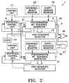
- An embodiment 1 of the invention is shown in Fig. 2.
- the pseudorandom bit sequence generator 3 produces a pseudorandom bit sequence on output line 5.
- the pseudorandom bit sequence generator 3 can be any type of bit sequence generator that produces a sequence with statistical properties that approximates those of a random bit sequence generator. Bit sequence generators which produce maximum-length bit sequences (m-sequences) are frequently used for this purpose and are described in numerous textbooks, e.g. W. Wesley Peterson, Error Correcting Codes , M.I.T. Press/John Wiley & Sons, Inc., New York, 1961, pp. 147-48.
- a predetermined number of the most recent bits of the pseudorandom bit sequence reside in a shift register within the pseudorandom bit sequence generator 3.
- the pseudorandom bit sequence generator 3 determines the next bit of the sequence (which will be referred to herein as the feedback bit) from the contents of the shift register and places it on output line 7.
- the feedback bit is usually allowed to pass through the bit-balancing unit 9 to the data input line 11 of the shift register and enter the shift register when the contents of the shift register are shifted by an appropriate transition in the clock signal supplied by clock 13. After the shift, the oldest bit stored in the shift register appears on the output line 5. Thus, a new bit of the pseudorandom bit sequence is produced on output line 5 with each appropriate transition of the clock signal.
- An end sequence is stored in end-sequence detector 15.
- the end-sequence detector 15 issues an end-sequence alert to to statistical control unit 9.
- a stored modifier bit sequence is then fed bit-by-bit on data input line 11 to the shift register in the pseudorandom bit sequence generator 3 rather than the feedback bit sequence appearing on line 7.
- the modifier bit sequence marks the actual end of the pseudorandom sequence appearing on line 5.
- the modifier bit sequence can be used to balance the "0's" and "1's” in the pseudorandom bit sequence appearing on line 5. For example, if the number of "1's” exceeds by one the number of "0's” in the pseudorandom bit sequence beginning with a start sequence and concluding with the end sequence, then the modifier bit sequence could consist of a single “0” or perhaps the sequence "0", "0", "1". Similarly, if the unbalance were in favor of "0's”, then the modifier bit sequence could consist of a single “1” or perhaps the sequence "1", "0", "1".
- the pseudorandom bit sequence that appears on line 5 consists of contiguous subsequences.
- a subsequence begins with a start sequence and ends at the beginning of the next start sequence.
- a trailing bit can be either a feedback bit or a modifier bit. It is not required that trailing bits be exclusively feedback bits from the start sequence to the end of the end sequence.
- interesting statistical properties can be obtained by inserting one or more modifier bits after the start sequence and before the occurrence of the end-sequence alert.
- the derivation of one or more modifier bits can be based on a statistic of a subsequence. For example, suppose the statistic is an unbalance in "0's" and "1's” in the start sequence and feedback trailing bits in a subsequence. Modifier bits designed to compensate for this unbalance could be inserted in the subsequence after the end-sequence alert thereby obtaining a subsequence that is balanced in "0's" and "1's”. One might also obtain a balance by inserting the compensating modifier bits anywhere in the next subsequence. Then the balancing effect takes place over many subsequences.
- the derivation of one or more modifier bits can also be based simply on obtaining a change in a statistical property of the pseudorandom bit sequence. For example, if each subsequence in a pseudorandom bit sequence is a specific in-sequence, then all of the subsequences would have the same length. One might not like the periodicity associated with such a pseudorandom bit sequence and one might choose to enter modifier bits at pseudorandom intervals in the specific m-sequence thereby obtaining a pseudorandom bit sequence consisting of subsequences of different lengths. In this case, one is inserting modifier bits to obtain a different probability density function for the lengths of the subsequences that make up the pseudorandom bit sequence.
- the start sequence is stored in start-sequence register 19.
- the statistical control unit 9 places a signal on control line 21 and thereby causes the contents of the start-sequence register 19 to be loaded into the shift register of pseudorandom bit sequence generator 3 on the next appropriate clock-signal transition after the last bit of the subsequence has appeared on output line 5. The process described above is then repeated.
- the feedback-bit generating process utilized by pseudorandom bit sequence generator 3 consists of performing certain logical operations on the states of two or more stages of the shift register in pseudorandom bit sequence generator 3.
- the selection of shift-register stages for this purpose is accomplished by sequence-select register 23.
- Pseudorandom bit sequence generator 31 operates in the same way as pseudorandom bit sequence generator 3 except for the clocking.
- the clock signal for pseudorandom bit sequence generator 31 is obtained from line 21 which means that a new bit is produced on output line 33 each time a start sequence is entered into pseudorandom bit sequence generator 3.
- control unit 17 causes a "1" to appear on control line 35, the pseudorandom bit sequence produced by pseudorandom bit sequence generator 31 passes through AND gate 37 to EXCLUSIVE OR gate 39. If the bit produced by pseudorandom bit sequence generator 31 is a "0", the pseudorandom bit sequence produced by pseudorandom bit sequence generator 3 will pass through EXCLUSIVE OR gate 39 unchanged. If the bit produced by pseudorandom bit sequence generator 31 is a "1”, the pseudorandom bit sequence produced by pseudorandom bit sequence generator 3 is inverted in passing through EXCLUSIVE OR gate 39.
- the invention relates to a method for determining the rotation of a medium through which a light beam propagates by modulating the light beam with a primary pseudorandom bit sequence, a primary pseudorandom bit sequence consisting of a plurality of contiguous P sequences, each P subsequence consisting of a start sequence of predetermined length followed by a sequence of trailing bits.
Applications Claiming Priority (2)
| Application Number | Priority Date | Filing Date | Title |
|---|---|---|---|
| US255391 | 1999-02-22 | ||
| US09/255,391 US6115125A (en) | 1999-02-22 | 1999-02-22 | Pseudorandom-bit-sequence modulated fiber-optic gyro |
Publications (3)
| Publication Number | Publication Date |
|---|---|
| EP1031817A2 true EP1031817A2 (de) | 2000-08-30 |
| EP1031817A3 EP1031817A3 (de) | 2003-08-06 |
| EP1031817B1 EP1031817B1 (de) | 2016-06-29 |
Family
ID=22968116
Family Applications (1)
| Application Number | Title | Priority Date | Filing Date |
|---|---|---|---|
| EP00103347.1A Expired - Lifetime EP1031817B1 (de) | 1999-02-22 | 2000-02-22 | Faseroptischer Kreisel mit Pseudozufallssequenzmodulation |
Country Status (4)
| Country | Link |
|---|---|
| US (2) | US6115125A (de) |
| EP (1) | EP1031817B1 (de) |
| JP (1) | JP4297576B2 (de) |
| IL (1) | IL132255A (de) |
Families Citing this family (10)
| Publication number | Priority date | Publication date | Assignee | Title |
|---|---|---|---|---|
| US6636553B1 (en) * | 1998-12-29 | 2003-10-21 | Texas Instruments Incorporated | Pseudorandom noise generator for WCDMA |
| US6115125A (en) * | 1999-02-22 | 2000-09-05 | Litton Systems Inc. | Pseudorandom-bit-sequence modulated fiber-optic gyro |
| US7818443B2 (en) * | 2000-12-01 | 2010-10-19 | O2Micro International Ltd. | Low power digital audio decoding/playing system for computing devices |
| US7522964B2 (en) * | 2000-12-01 | 2009-04-21 | O2Micro International Limited | Low power digital audio decoding/playing system for computing devices |
| US7522965B2 (en) * | 2000-12-01 | 2009-04-21 | O2Micro International Limited | Low power digital audio decoding/playing system for computing devices |
| US7890741B2 (en) | 2000-12-01 | 2011-02-15 | O2Micro International Limited | Low power digital audio decoding/playing system for computing devices |
| US6737846B1 (en) * | 2002-12-17 | 2004-05-18 | Green Power Technologies Ltd. | Method and voltage feedback circuitry for improving the performance of APFC converters |
| US7194496B2 (en) * | 2003-05-02 | 2007-03-20 | Spirent Communications Of Rockville, Inc. | System and method for producing functions for generating pseudo-random bit sequences |
| CN101482413B (zh) * | 2009-02-24 | 2010-12-01 | 北京航天时代光电科技有限公司 | 一种改善光纤陀螺低角速率下标度因数非线性的方法 |
| CN111064067B (zh) * | 2019-12-19 | 2021-05-25 | 中国兵器装备研究院 | 光纤激光相干合成系统 |
Citations (1)
| Publication number | Priority date | Publication date | Assignee | Title |
|---|---|---|---|---|
| US3984668A (en) | 1974-03-20 | 1976-10-05 | U.S. Philips Corporation | Method for generating pseudo-random bit sequence words and a device for carrying out the method |
Family Cites Families (6)
| Publication number | Priority date | Publication date | Assignee | Title |
|---|---|---|---|---|
| US4291386A (en) * | 1978-11-30 | 1981-09-22 | Sperry Corporation | Pseudorandom number generator |
| DE3580679D1 (de) * | 1984-02-06 | 1991-01-03 | British Broadcasting Corp | Binaere pseudo-zufalls-reihengeneratoren. |
| DE59001619D1 (de) * | 1990-02-12 | 1993-07-08 | Litef Gmbh | Faseroptisches sagnac-interferometer mit digitaler phasenrampenrueckstellung zur drehratenmessung. |
| DE69326681T2 (de) * | 1993-04-06 | 2000-02-10 | Hewlett Packard Co | Verfahren und Apparat zum Erzeugen von linearen Rückführungsschieberegistersequenzen |
| US5682241A (en) * | 1996-03-11 | 1997-10-28 | Litton Systems, Inc. | Method and apparatus for overcoming cross-coupling in a fiber optic gyroscope employing overmodulation |
| US6115125A (en) * | 1999-02-22 | 2000-09-05 | Litton Systems Inc. | Pseudorandom-bit-sequence modulated fiber-optic gyro |
-
1999
- 1999-02-22 US US09/255,391 patent/US6115125A/en not_active Expired - Lifetime
- 1999-10-06 IL IL13225599A patent/IL132255A/en not_active IP Right Cessation
- 1999-12-09 JP JP35038199A patent/JP4297576B2/ja not_active Expired - Fee Related
-
2000
- 2000-02-22 EP EP00103347.1A patent/EP1031817B1/de not_active Expired - Lifetime
- 2000-06-30 US US09/607,471 patent/US6307631B1/en not_active Expired - Lifetime
Patent Citations (1)
| Publication number | Priority date | Publication date | Assignee | Title |
|---|---|---|---|---|
| US3984668A (en) | 1974-03-20 | 1976-10-05 | U.S. Philips Corporation | Method for generating pseudo-random bit sequence words and a device for carrying out the method |
Also Published As
| Publication number | Publication date |
|---|---|
| IL132255A (en) | 2004-06-20 |
| JP4297576B2 (ja) | 2009-07-15 |
| EP1031817B1 (de) | 2016-06-29 |
| JP2000241169A (ja) | 2000-09-08 |
| EP1031817A3 (de) | 2003-08-06 |
| US6115125A (en) | 2000-09-05 |
| IL132255A0 (en) | 2001-03-19 |
| US6307631B1 (en) | 2001-10-23 |
Similar Documents
| Publication | Publication Date | Title |
|---|---|---|
| JP4034847B2 (ja) | 過変調を採用している光ファイバ・ジャイロスコープにおけるクロスカップリングを抑制するための方法および装置 | |
| JPH05272982A (ja) | 回転速度測定のための方法および装置 | |
| US6115125A (en) | Pseudorandom-bit-sequence modulated fiber-optic gyro | |
| JPH0587580A (ja) | 回転速度の測定のための光フアイバサニヤツク干渉計 | |
| US5189488A (en) | Fiber optical gyroscope utilizing orthogonal sequences | |
| EP0760463B1 (de) | Faseroptischer Kreisel | |
| CN107430002A (zh) | 用于光纤陀螺仪的零均值控制的相位调制器以及光纤陀螺仪 | |
| US5513003A (en) | Fiber optic gyro digital control with rate extension | |
| US6130755A (en) | Fiber-optic gyro utilizing pseudorandom-bit-sequence light modulation | |
| JPH1194563A (ja) | 光ファイバジャイロスコープ用速度制御ループ | |
| US5305086A (en) | Two step demodulation synchronous detector | |
| EP0935121B1 (de) | Verfahren zur Verbesserung der Leistung eines optischen Faserkreisels | |
| JP4520560B2 (ja) | 光ファイバジャイロの縞数を決定するための方法および装置 | |
| US6008903A (en) | Method for compensating for fringe visibility errors in a fiber-optic gyro | |
| US5999260A (en) | Method and apparatus for initialization of a fiber optic gyroscope | |
| KR100719648B1 (ko) | 광섬유자이로스코프에서교차결선을극복하기위한장치및방법 | |
| JPH07134039A (ja) | 光ファイバジャイロ | |
| JP3493487B2 (ja) | 光干渉角速度計 | |
| CN114838804A (zh) | 基于弱光栅阵列和脉冲编码的分布式振动测量装置及方法 | |
| JPH07134038A (ja) | 光ファイバジャイロ |
Legal Events
| Date | Code | Title | Description |
|---|---|---|---|
| PUAI | Public reference made under article 153(3) epc to a published international application that has entered the european phase |
Free format text: ORIGINAL CODE: 0009012 |
|
| AK | Designated contracting states |
Kind code of ref document: A2 Designated state(s): AT BE CH CY DE DK ES FI FR GB GR IE IT LI LU MC NL PT SE |
|
| AX | Request for extension of the european patent |
Free format text: AL;LT;LV;MK;RO;SI |
|
| PUAL | Search report despatched |
Free format text: ORIGINAL CODE: 0009013 |
|
| AK | Designated contracting states |
Designated state(s): AT BE CH CY DE DK ES FI FR GB GR IE IT LI LU MC NL PT SE |
|
| AX | Request for extension of the european patent |
Extension state: AL LT LV MK RO SI |
|
| RIC1 | Information provided on ipc code assigned before grant |
Ipc: 7H 01S 3/067 B Ipc: 7G 01C 19/72 A |
|
| 17P | Request for examination filed |
Effective date: 20040204 |
|
| AKX | Designation fees paid |
Designated state(s): DE FR GB IT |
|
| RAP1 | Party data changed (applicant data changed or rights of an application transferred) |
Owner name: NORTHROP GRUMMAN GUIDANCE AND ELECTRONICS COMPANY, |
|
| 17Q | First examination report despatched |
Effective date: 20080624 |
|
| GRAP | Despatch of communication of intention to grant a patent |
Free format text: ORIGINAL CODE: EPIDOSNIGR1 |
|
| INTG | Intention to grant announced |
Effective date: 20150710 |
|
| GRAS | Grant fee paid |
Free format text: ORIGINAL CODE: EPIDOSNIGR3 |
|
| INTG | Intention to grant announced |
Effective date: 20160111 |
|
| GRAA | (expected) grant |
Free format text: ORIGINAL CODE: 0009210 |
|
| AK | Designated contracting states |
Kind code of ref document: B1 Designated state(s): DE FR GB IT |
|
| REG | Reference to a national code |
Ref country code: GB Ref legal event code: FG4D |
|
| REG | Reference to a national code |
Ref country code: DE Ref legal event code: R096 Ref document number: 60049366 Country of ref document: DE |
|
| REG | Reference to a national code |
Ref country code: FR Ref legal event code: PLFP Year of fee payment: 18 |
|
| REG | Reference to a national code |
Ref country code: DE Ref legal event code: R097 Ref document number: 60049366 Country of ref document: DE |
|
| PLBE | No opposition filed within time limit |
Free format text: ORIGINAL CODE: 0009261 |
|
| STAA | Information on the status of an ep patent application or granted ep patent |
Free format text: STATUS: NO OPPOSITION FILED WITHIN TIME LIMIT |
|
| PGFP | Annual fee paid to national office [announced via postgrant information from national office to epo] |
Ref country code: GB Payment date: 20170216 Year of fee payment: 18 |
|
| 26N | No opposition filed |
Effective date: 20170330 |
|
| STAA | Information on the status of an ep patent application or granted ep patent |
Free format text: STATUS: NO OPPOSITION FILED WITHIN TIME LIMIT |
|
| REG | Reference to a national code |
Ref country code: FR Ref legal event code: PLFP Year of fee payment: 19 |
|
| GBPC | Gb: european patent ceased through non-payment of renewal fee |
Effective date: 20180222 |
|
| PG25 | Lapsed in a contracting state [announced via postgrant information from national office to epo] |
Ref country code: GB Free format text: LAPSE BECAUSE OF NON-PAYMENT OF DUE FEES Effective date: 20180222 |
|
| PGFP | Annual fee paid to national office [announced via postgrant information from national office to epo] |
Ref country code: IT Payment date: 20190225 Year of fee payment: 20 Ref country code: DE Payment date: 20190219 Year of fee payment: 20 |
|
| PGFP | Annual fee paid to national office [announced via postgrant information from national office to epo] |
Ref country code: FR Payment date: 20190219 Year of fee payment: 20 |
|
| REG | Reference to a national code |
Ref country code: DE Ref legal event code: R071 Ref document number: 60049366 Country of ref document: DE |