EP1031774B1 - Metalldichtung - Google Patents
Metalldichtung Download PDFInfo
- Publication number
- EP1031774B1 EP1031774B1 EP00301414A EP00301414A EP1031774B1 EP 1031774 B1 EP1031774 B1 EP 1031774B1 EP 00301414 A EP00301414 A EP 00301414A EP 00301414 A EP00301414 A EP 00301414A EP 1031774 B1 EP1031774 B1 EP 1031774B1
- Authority
- EP
- European Patent Office
- Prior art keywords
- elastic metal
- gasket
- flange
- plates
- elastic
- Prior art date
- Legal status (The legal status is an assumption and is not a legal conclusion. Google has not performed a legal analysis and makes no representation as to the accuracy of the status listed.)
- Expired - Lifetime
Links
Images


Classifications
-
- F—MECHANICAL ENGINEERING; LIGHTING; HEATING; WEAPONS; BLASTING
- F16—ENGINEERING ELEMENTS AND UNITS; GENERAL MEASURES FOR PRODUCING AND MAINTAINING EFFECTIVE FUNCTIONING OF MACHINES OR INSTALLATIONS; THERMAL INSULATION IN GENERAL
- F16J—PISTONS; CYLINDERS; SEALINGS
- F16J15/00—Sealings
- F16J15/02—Sealings between relatively-stationary surfaces
- F16J15/06—Sealings between relatively-stationary surfaces with solid packing compressed between sealing surfaces
- F16J15/08—Sealings between relatively-stationary surfaces with solid packing compressed between sealing surfaces with exclusively metal packing
- F16J15/0818—Flat gaskets
- F16J15/0825—Flat gaskets laminated
-
- F—MECHANICAL ENGINEERING; LIGHTING; HEATING; WEAPONS; BLASTING
- F16—ENGINEERING ELEMENTS AND UNITS; GENERAL MEASURES FOR PRODUCING AND MAINTAINING EFFECTIVE FUNCTIONING OF MACHINES OR INSTALLATIONS; THERMAL INSULATION IN GENERAL
- F16J—PISTONS; CYLINDERS; SEALINGS
- F16J15/00—Sealings
- F16J15/02—Sealings between relatively-stationary surfaces
- F16J15/06—Sealings between relatively-stationary surfaces with solid packing compressed between sealing surfaces
- F16J15/08—Sealings between relatively-stationary surfaces with solid packing compressed between sealing surfaces with exclusively metal packing
- F16J15/0818—Flat gaskets
- F16J2015/0837—Flat gaskets with an edge portion folded over a second plate or shim
-
- F—MECHANICAL ENGINEERING; LIGHTING; HEATING; WEAPONS; BLASTING
- F16—ENGINEERING ELEMENTS AND UNITS; GENERAL MEASURES FOR PRODUCING AND MAINTAINING EFFECTIVE FUNCTIONING OF MACHINES OR INSTALLATIONS; THERMAL INSULATION IN GENERAL
- F16J—PISTONS; CYLINDERS; SEALINGS
- F16J15/00—Sealings
- F16J15/02—Sealings between relatively-stationary surfaces
- F16J15/06—Sealings between relatively-stationary surfaces with solid packing compressed between sealing surfaces
- F16J15/08—Sealings between relatively-stationary surfaces with solid packing compressed between sealing surfaces with exclusively metal packing
- F16J15/0818—Flat gaskets
- F16J2015/0856—Flat gaskets with a non-metallic coating or strip
Definitions
- the present invention relates to a combination of a metal gasket a synthetic resin flange and a metal flange.
- a flange for use in the inlet system of an engine has typically been made of aluminium.
- a synthetic resin obtained, for example, by reinforcing 6-nylon with glass fiber is used instead. This is because it is possible to reduce weight and costs using such a material.
- Synthetic resins used in making flanges generally have a low rigidity, a large thermal strain (deformation when heated), and a high deformation under an external force. It is therefore difficult to achieve the sealing property as a gasket, compared with flanges made of aluminium.
- gaskets used for such synthetic resin flanges are made of rubber, for example rubber O-rings. This is because a large amount of compression and resilience can be obtained under a small load.
- Figure 10 shows an example of a construction, in which a rubber product sealing member B is used between a resin flange 1 and an aluminium flange 2.
- a groove 1a, into which the rubber product sealing member B is inserted, is formed in the resin flange 1.
- the rubber material can be changed from HNBR to, for example, fluorocarbon rubber and fluorosilicone rubber to improve the sealing property
- the sealing property is reduced at low temperatures if a fluorocarbon rubber is used, while the costs are increased if a fluorosilicone rubber is used.
- the present invention has been made in order to address at least some of the problems associated with using a rubber gasket with a resin flange.
- An object of the invention is to provide a metal gasket having a high reliability wherein an appropriate amount of compression and resilience is secured and buckling is suppressed. In this way, it is suitable for long term use owing to the fact that only the elastically deformable region is used in processes, in which beads are compressed, when a flange is secured by screwing, by using a structure, which can suppress compressing load on the beads to a low value.
- US-A-5,087,058 relates to a metal gasket for a manifold.
- US-A-5,277,434 relates to a multi-layer cylinder head gasket.
- Fig. 1 shows an explanatory embodiment not according to the present invention.
- reference numeral 1 represents a resin flange; 2 an aluminium flange; and A a metal gasket.
- the metal gasket A two elastic metal plates 3, 3 superposed on each other are used as core material.
- a half bead 3a 3a bent stepwise is formed so that they have steps opposite to each other.
- Parts of the elastic metal plates superposed on each other in the neighborhood of the half bead are jointed to each other by using appropriate means.
- a rubber coating or an elastic layer made of rubber mounted later, which is contacted with a flange is formed on a surface of the half beads 3a, 3a.
- 4 is a metal shim plate superposed on the part of the elastic metal plate superposed on the other in the neighborhood of the half bead 3a and jointed thereto.
- Stainless steel plates such as SUS301H, etc. are used for the elastic metal plates 3, 3.
- the most preferable thickness is 0.1 mm.
- plates 0.1 mm to 0.3 mm thick can be used.
- plates 0.1 mm to 0.2 mm thick are apt to give the parts of beads a large amount of compression and resilience under a small load. More preferably it is desirable to use plates 0.1 mm to 0.15 mm thick.
- Rubber such as NBR and HNBR is used for the rubber elastic layers formed on surfaces of the half beads 3a, 3a of the elastic metal plates 3, 3.
- the kind of rubber can be selected arbitrarily, depending on environment, in which the gasket is used.
- nitryl rubber styrene butadiene rubber, isoprene rubber, chloroprene rubber, butadiene rubber, butyl rubber, ethylene-propylene rubber, fluorocarbon rubber, silicone rubber, chlorosulphonized polyethylene, ethylene vynil acetate rubber, polyethylene chloride, butyl chloride rubber, epichlorohydrin rubber, nitryl isoprene rubber, natural rubber, etc.
- nitryl rubber styrene butadiene rubber, isoprene rubber, chloroprene rubber, butadiene rubber, butyl rubber, ethylene-propylene rubber, fluorocarbon rubber, silicone rubber, chlorosulphonized polyethylene, ethylene vynil acetate rubber, polyethylene chloride, butyl chloride rubber, epichlorohydrin rubber, nitryl isoprene rubber,
- Rubber, with which the metal plate is coated is preferably 20 to 100 ⁇ m thick. Not only rubber which is not foamed but also foamed rubber may be used therefor. In this case thickness comprised between 150 and 1500 ⁇ m can be used.
- ring-shaped product 3b having a U-shaped cross-section made of rubber several mm thick may be mounted later on the metal plates, as indicated in Fig. 2.
- the metal gasket A constructed as described above has the half beads 3a, 3a bent stepwise formed so as to have steps opposite to each other, when the flanges are tightened, both the half beads 3a, 3a are brought into contact elastically with surfaces of the flanges to form sealing planes.
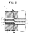
- Fig. 3 shows an example not according to the present invention, in which two metal gaskets A indicated in Fig. 1 are superposed on each other to be arranged.
- Fig. 4 shows an example not according to the present invention, in which the shim plates can be omitted by disposing a step 1a in the resin flange. Since it is possible to change the amount of deformation of the half beads by this construction, regulation can be effected so as to give the beads a large amount of compression and at the same time a large amount of resilience by a small load.
- Fig. 5 shows a part P in Fig. 4 in detail in an enlarged scale.
- 3 indicates an elastic metal plate 0.1 mm thick and 5a and 5b represent elastic layers formed by coating with rubber.
- the rubber elastic layer 5a on the elastic metal plate 3 on the outer side is 50 to 100 ⁇ m thick, while the rubber elastic layer 5b on the elastic metal plate 3 on the inner side is 10 to 30 ⁇ m thick.
- Fig. 6 shows an example not according to the present invention, in which a single elastic metal plate 3 having a half bead 3a (A') is superposed further on one metal gasket A between the two metal gaskets A, A superposed on each other in Fig. 4 in a state where the half beads are superposed on each other.
- A' half bead 3a
- Fig. 7 shows an embodiment of the present invention.
- a soft foam rubber layer is formed on the half bead 3a of the elastic metal plate brought into contact with the resin flange 1 between the two elastic metal plates 3, 3 constituting the metal gasket A and further the relevant elastic metal plate 3 is shorter than the other elastic metal plate 3, the two elastic metal plates 3, 3 being put between two shim plates 4, 4.
- Fig. 8 shows compression-resilience characteristics of the metal gasket according to the present invention
- Fig. 9 shows compression-resilience characteristics of a prior art metal gasket.
- These figures indicate variations of the linear pressure (load) P applied to the bead with respect to variations of the displacement L of the bead.
- Y 1 is a curve obtained when a prior art bead is compressed by a total pression
- Y 2 indicates that it is possible to decrease the linear pressure (compression strength) of the bead by using shim plates together.
- a load of 85 kgf/cm is required in order to give the bead a displacement of about 1.5 mm.
- a small load is sufficient to give the same displacement by using shim plates on the outer periphery side of the bead plates.
- the amount of compression and resilience can be arbitrarily regulated by varying the height of the beads, and the thickness of shim plates.
- the amount of compression can be increased by decreasing the thickness of the shim plates for a same height of the beads.
- the explanatory embodiments indicated in Figs. 1 to 6 and the claimed embodiment indicated in Fig. 7, are based on the construction, in which two elastic metal plates having half beads are superposed on each other so that the half beads are directed opposite to each other.
- the beads may be full beads.
- the sealing property may be secured even by a construction consisting of one elastic metal plate having a half bead or a full bead.
- the core material of the gasket is metal having a definite form, it can be mounted automatically and workability (easiness of mounting) can be maintained at a same level as in case where aluminium flanges are used.
Landscapes
- Engineering & Computer Science (AREA)
- General Engineering & Computer Science (AREA)
- Mechanical Engineering (AREA)
- Gasket Seals (AREA)
Claims (6)
- Kombination einer Metalldichtung (A), eines Kunstharzflansches und eines Metallflansches, wobei die Metalldichtung zwischen dem Kunstharzflansch (1) und dem Metallflansch (2) angeordnet ist, und wobei eine Stufe (1a) an dem Kunstharzflansch zur Aufnahme der Dichtung ausgebildet ist, und wobei die Dichtung folgendes aufweist:vier elastische Metallplatten (3), wobei an jeder der elastischen Metallplatten ein Halb-Wulst (3a) ausgebildet ist, und wobei die elastischen Metallplatten so gestaltet sind, dass zwei Sätze von elastischen Metallplatten übereinander angeordnet sind, wobei jeder Satz zwei elastische Metallplatten umfasst, die übereinander angeordnet sind, damit sie so verbunden sind, dass die Halb-Wülste gegenüberliegend voneinander ausgerichtet sind;die fünfte elastische Metallplatte, wobei an der fünften elastischen Metallplatte ein Halb-Wulst ausgebildet ist, und wobei die fünfte elastische Metallplatte so an den vier elastischen Metallplatten angeordnet ist, dass der Halb-Wulst der fünften elastischen Metallplatte über einer der Halb-Wülste der vier elastischen Metallplatten angeordnet ist.
- Kombination einer Metalldichtung (A), eines Kunstharzflansches und eines Metallflansches, wobei die Metalldichtung zwischen dem Kunstharzflansch (1) und dem Metallflansch (2) angeordnet ist, und wobei die Dichtung (A) folgendes aufweist:vier elastische Metallplatten (3), wobei an jeder der elastischen Metallplatten ein Halb-Wulst (3a) ausgebildet ist, und wobei die elastischen Metallplatten so gestaltet sind, dass zwei Sätze von elastischenMetallplatten übereinander angeordnet sind, wobei jeder Satz zwei elastische Metallplatten umfasst, die übereinander angeordnet sind, damit sie so verbunden sind, dass die Halb-Wülste gegenüberliegend voneinander ausgerichtet sind;Beilagscheibenplatten (4), die über den elastischen Metallplatten außerhalb der Halb-Wülste angeordnet sind, um damit verbunden zu werden; unddie fünfte elastische Metallplatte, wobei an der fünften elastischen Metallplatte ein Halb-Wulst ausgebildet ist, und wobei die fünfte elastische Metallplatte so an den vier elastischen Metallplatten angeordnet ist, dass der Halb-Wulst der fünften elastischen Metallplatte über einer der Halb-Wülste der vier elastischen Metallplatten angeordnet ist.
- Kombination einer Metalldichtung (A), eines Kunstharzflansches und eines Metallflansches, wobei die Metalldichtung zwischen dem Kunstharzflansch (1) und dem Metallflansch (2) angeordnet ist, und wobei die Dichtung (A) folgendes aufweist:zwei elastische Metallplatten (3), wobei an jeder der elastischen Metallplatten ein Halb-Wulst (3a) ausgebildet ist, und wobei die elastischen Metallplatten übereinander angeordnet sind, um verbunden zu werden, so dass die Halb-Wülste gegenüberliegend voneinander ausgerichtet sind, und wobei eine der elastischen Metallplatten kürzer als die andere ist; undBeilagscheibenplatten (4), die über den elastischen Metallplatten außerhalb der Halb-Wülste angeordnet sind, um damit verbunden zu werden.
- Kombination nach Anspruch 3,
dadurch gekennzeichnet, dass
ein röhrenförmiger Metallkragen (6) in den Harzflansch eingesetzt ist und außerhalb des Flansches in Richtung der Metalldichtung herausragt. - Kombination nach einem der vorhergehenden Ansprüche 1 bis 4,
dadurch gekennzeichnet, dass
unter Oberflächen der elastischen Metallplatten ein Gummi oder eine Schaumgummischicht an wenigstens einer Halb-Wulst-Oberfläche ausgebildet ist, die in Kontakt mit dem Kunstharzflansch gebracht ist. - Kombination nach einem der vorhergehenden Ansprüche 1 bis 5,
dadurch gekennzeichnet, dass
jede der elastischen Metallplatten eine Dicke von 0,1 mm bis 0,3 mm hat.
Applications Claiming Priority (2)
| Application Number | Priority Date | Filing Date | Title |
|---|---|---|---|
| JP4627799 | 1999-02-24 | ||
| JP11046277A JP2000240797A (ja) | 1999-02-24 | 1999-02-24 | メタルガスケット |
Publications (3)
| Publication Number | Publication Date |
|---|---|
| EP1031774A2 EP1031774A2 (de) | 2000-08-30 |
| EP1031774A3 EP1031774A3 (de) | 2001-10-10 |
| EP1031774B1 true EP1031774B1 (de) | 2004-01-14 |
Family
ID=12742746
Family Applications (1)
| Application Number | Title | Priority Date | Filing Date |
|---|---|---|---|
| EP00301414A Expired - Lifetime EP1031774B1 (de) | 1999-02-24 | 2000-02-23 | Metalldichtung |
Country Status (5)
| Country | Link |
|---|---|
| US (1) | US6422572B1 (de) |
| EP (1) | EP1031774B1 (de) |
| JP (1) | JP2000240797A (de) |
| CA (1) | CA2299062C (de) |
| DE (1) | DE60007673T2 (de) |
Families Citing this family (22)
| Publication number | Priority date | Publication date | Assignee | Title |
|---|---|---|---|---|
| DE20019412U1 (de) * | 2000-11-15 | 2001-01-11 | REINZ Dichtungs GmbH u. Co. KG, 89233 Neu-Ulm | Zylinderkopfdichtung |
| US6682079B2 (en) * | 2002-05-31 | 2004-01-27 | Federal-Mogul World Wide, Inc. | Metal plate gasket |
| DE10310683A1 (de) * | 2003-03-12 | 2004-10-07 | Federal-Mogul Sealing Systems Gmbh | Flachdichtung, insbesondere Zylinderkopfdichtung |
| DE10346429A1 (de) * | 2003-10-07 | 2005-06-09 | Bayerische Motoren Werke Ag | Dichtung |
| US20060131817A1 (en) * | 2004-12-17 | 2006-06-22 | Kerelchuk Colin J | Gasket assembly for joints experiencing thermally induced movement |
| US7401790B2 (en) * | 2005-01-11 | 2008-07-22 | Federal-Mogul World Wide, Inc. | Metal gasket with rigid seal |
| JP2007010099A (ja) * | 2005-07-04 | 2007-01-18 | Nichias Corp | 吸気ガスケット |
| JP4309409B2 (ja) * | 2006-05-16 | 2009-08-05 | 石川ガスケット株式会社 | メタルガスケット |
| US7726662B2 (en) * | 2006-07-10 | 2010-06-01 | Dana Automotive Systems Group, Llc | Stopped-active type cylinder head gasket |
| JP2010138957A (ja) * | 2008-12-10 | 2010-06-24 | Toyoda Gosei Co Ltd | ガスケット |
| CN102549318B (zh) * | 2009-08-11 | 2014-09-24 | 费德罗-莫格尔公司 | 双金属静态垫圈及其构造方法 |
| KR101509784B1 (ko) * | 2009-09-03 | 2015-04-06 | 현대자동차주식회사 | 차량의 배기관용 가스켓 |
| JP5880030B2 (ja) * | 2011-07-11 | 2016-03-08 | Nok株式会社 | 金属ガスケットによるシール構造 |
| US20130082444A1 (en) * | 2011-09-30 | 2013-04-04 | Caterpillar, Inc. | Service Gasket For Internal Combustion Engine And Method |
| JP6501540B2 (ja) * | 2015-02-04 | 2019-04-17 | 本田技研工業株式会社 | メタルガスケット |
| US9528466B2 (en) * | 2015-02-27 | 2016-12-27 | Federal-Mogul Corporation | Cylinder head gasket |
| JP5911163B1 (ja) * | 2015-05-10 | 2016-04-27 | 有限会社 東進車輌工業 | 排気管用メタルガスケット |
| JP6527548B2 (ja) * | 2017-05-23 | 2019-06-05 | 本田技研工業株式会社 | フランジ接合構造 |
| WO2020095665A1 (ja) | 2018-11-05 | 2020-05-14 | Nok株式会社 | ガスケット及び密封構造 |
| US11703013B1 (en) * | 2022-03-03 | 2023-07-18 | Caterpillar Inc. | Engine head gasket having anti-preignition wrap and method of making same |
| DE102023121475A1 (de) * | 2023-08-10 | 2025-02-13 | Elringklinger Ag | Dichtungselement und Dichtungsanordnung |
| KR20250072297A (ko) * | 2023-11-16 | 2025-05-23 | 현대자동차주식회사 | 차량의 배기계용 가스켓 |
Family Cites Families (9)
| Publication number | Priority date | Publication date | Assignee | Title |
|---|---|---|---|---|
| DE970950C (de) * | 1953-03-24 | 1958-12-31 | Goetzewerke | Flachdichtung |
| JP2921941B2 (ja) * | 1990-08-13 | 1999-07-19 | 日本ガスケット株式会社 | マニホルド用金属ガスケット |
| US5375856A (en) * | 1992-01-22 | 1994-12-27 | Ishikawa Gasket Co., Ltd. | Protecting member for a gasket |
| US5277434A (en) * | 1992-09-11 | 1994-01-11 | Dana Corporation | Multiple layer cylinder head gasket |
| JP2730478B2 (ja) * | 1994-03-15 | 1998-03-25 | 国産部品工業株式会社 | メタルガスケット |
| JPH0814126A (ja) * | 1994-06-29 | 1996-01-16 | Honda Motor Co Ltd | V型エンジンの吸気装置 |
| US5601294A (en) * | 1995-05-01 | 1997-02-11 | Stritzke; Bernard G. | Head gasket |
| DE19516375A1 (de) * | 1995-05-04 | 1996-11-07 | Payen Goetze Gmbh | Metallische Flachdichtung |
| KR980008780U (ko) * | 1996-07-08 | 1998-04-30 | 김영귀 | 실린더 헤드의 기밀 유지구조 |
-
1999
- 1999-02-24 JP JP11046277A patent/JP2000240797A/ja active Pending
-
2000
- 2000-02-22 US US09/510,744 patent/US6422572B1/en not_active Expired - Lifetime
- 2000-02-22 CA CA002299062A patent/CA2299062C/en not_active Expired - Fee Related
- 2000-02-23 EP EP00301414A patent/EP1031774B1/de not_active Expired - Lifetime
- 2000-02-23 DE DE60007673T patent/DE60007673T2/de not_active Expired - Lifetime
Also Published As
| Publication number | Publication date |
|---|---|
| US6422572B1 (en) | 2002-07-23 |
| DE60007673D1 (de) | 2004-02-19 |
| JP2000240797A (ja) | 2000-09-05 |
| DE60007673T2 (de) | 2004-12-09 |
| CA2299062C (en) | 2009-04-28 |
| EP1031774A2 (de) | 2000-08-30 |
| CA2299062A1 (en) | 2000-08-24 |
| EP1031774A3 (de) | 2001-10-10 |
Similar Documents
| Publication | Publication Date | Title |
|---|---|---|
| EP1031774B1 (de) | Metalldichtung | |
| US6994354B2 (en) | Vibrationally decoupling gasket | |
| US4844484A (en) | Floating lip seal with reinforced flexible portion | |
| US6517085B2 (en) | Cylinder head gasket with partial resin coating | |
| US5975539A (en) | Composite gasket | |
| EP2143981B1 (de) | Dichtung zur Bereitstellung einer Abdichtung zwischen zwei Gegenständen | |
| EP0721077B1 (de) | Metalldichtung | |
| CN101091078A (zh) | 垫片 | |
| US7063327B2 (en) | Sealing element | |
| US7004477B2 (en) | Reduced load gasket | |
| JP2011117466A (ja) | ガスケット及び密封構造 | |
| US20040041354A1 (en) | Sealing device | |
| EP1306588B1 (de) | Metalldichtung mit einer partiellen Oberflächenbeschichtung | |
| US20200032904A1 (en) | Gasket | |
| US6981703B2 (en) | Cylinder head gasket | |
| JP3822661B2 (ja) | メタルガスケット | |
| JP2005291487A (ja) | 可撓性ストッパを備えたシーリングガスケット | |
| JP2009222196A (ja) | 空気ばね | |
| WO1985001100A1 (en) | Improved heat transfer apparatus | |
| EP0516356B1 (de) | Zylinderkopfdichtung | |
| JP2605613Y2 (ja) | ガスケット | |
| EP1544518A1 (de) | Zylinderkopfdichtung | |
| CN223447624U (zh) | 膨体四氟夹包齿形垫 | |
| ZA200603456B (en) | Liners for pumps | |
| GB2138512A (en) | Diaphragm pump |
Legal Events
| Date | Code | Title | Description |
|---|---|---|---|
| PUAI | Public reference made under article 153(3) epc to a published international application that has entered the european phase |
Free format text: ORIGINAL CODE: 0009012 |
|
| AK | Designated contracting states |
Kind code of ref document: A2 Designated state(s): DE FR GB Kind code of ref document: A2 Designated state(s): AT BE CH CY DE DK ES FI FR GB GR IE IT LI LU MC NL PT SE |
|
| AX | Request for extension of the european patent |
Free format text: AL;LT;LV;MK;RO;SI |
|
| PUAL | Search report despatched |
Free format text: ORIGINAL CODE: 0009013 |
|
| AK | Designated contracting states |
Kind code of ref document: A3 Designated state(s): AT BE CH CY DE DK ES FI FR GB GR IE IT LI LU MC NL PT SE |
|
| AX | Request for extension of the european patent |
Free format text: AL;LT;LV;MK;RO;SI |
|
| 17P | Request for examination filed |
Effective date: 20020319 |
|
| AKX | Designation fees paid |
Free format text: DE FR GB |
|
| 17Q | First examination report despatched |
Effective date: 20020719 |
|
| GRAP | Despatch of communication of intention to grant a patent |
Free format text: ORIGINAL CODE: EPIDOSNIGR1 |
|
| GRAS | Grant fee paid |
Free format text: ORIGINAL CODE: EPIDOSNIGR3 |
|
| GRAA | (expected) grant |
Free format text: ORIGINAL CODE: 0009210 |
|
| AK | Designated contracting states |
Kind code of ref document: B1 Designated state(s): DE FR GB |
|
| REG | Reference to a national code |
Ref country code: GB Ref legal event code: FG4D |
|
| REF | Corresponds to: |
Ref document number: 60007673 Country of ref document: DE Date of ref document: 20040219 Kind code of ref document: P |
|
| ET | Fr: translation filed | ||
| PLBE | No opposition filed within time limit |
Free format text: ORIGINAL CODE: 0009261 |
|
| STAA | Information on the status of an ep patent application or granted ep patent |
Free format text: STATUS: NO OPPOSITION FILED WITHIN TIME LIMIT |
|
| 26N | No opposition filed |
Effective date: 20041015 |
|
| PGFP | Annual fee paid to national office [announced via postgrant information from national office to epo] |
Ref country code: FR Payment date: 20140211 Year of fee payment: 15 |
|
| PGFP | Annual fee paid to national office [announced via postgrant information from national office to epo] |
Ref country code: GB Payment date: 20140219 Year of fee payment: 15 |
|
| PGFP | Annual fee paid to national office [announced via postgrant information from national office to epo] |
Ref country code: DE Payment date: 20140417 Year of fee payment: 15 |
|
| REG | Reference to a national code |
Ref country code: DE Ref legal event code: R119 Ref document number: 60007673 Country of ref document: DE |
|
| GBPC | Gb: european patent ceased through non-payment of renewal fee |
Effective date: 20150223 |
|
| REG | Reference to a national code |
Ref country code: FR Ref legal event code: ST Effective date: 20151030 |
|
| PG25 | Lapsed in a contracting state [announced via postgrant information from national office to epo] |
Ref country code: DE Free format text: LAPSE BECAUSE OF NON-PAYMENT OF DUE FEES Effective date: 20150901 Ref country code: GB Free format text: LAPSE BECAUSE OF NON-PAYMENT OF DUE FEES Effective date: 20150223 |
|
| PG25 | Lapsed in a contracting state [announced via postgrant information from national office to epo] |
Ref country code: FR Free format text: LAPSE BECAUSE OF NON-PAYMENT OF DUE FEES Effective date: 20150302 |