EP1031762A2 - Boite-pont manuelle - Google Patents
Boite-pont manuelle Download PDFInfo
- Publication number
- EP1031762A2 EP1031762A2 EP00103972A EP00103972A EP1031762A2 EP 1031762 A2 EP1031762 A2 EP 1031762A2 EP 00103972 A EP00103972 A EP 00103972A EP 00103972 A EP00103972 A EP 00103972A EP 1031762 A2 EP1031762 A2 EP 1031762A2
- Authority
- EP
- European Patent Office
- Prior art keywords
- gear
- speed
- intermediate shaft
- input
- gears
- Prior art date
- Legal status (The legal status is an assumption and is not a legal conclusion. Google has not performed a legal analysis and makes no representation as to the accuracy of the status listed.)
- Granted
Links
Images

Classifications
-
- F—MECHANICAL ENGINEERING; LIGHTING; HEATING; WEAPONS; BLASTING
- F16—ENGINEERING ELEMENTS AND UNITS; GENERAL MEASURES FOR PRODUCING AND MAINTAINING EFFECTIVE FUNCTIONING OF MACHINES OR INSTALLATIONS; THERMAL INSULATION IN GENERAL
- F16H—GEARING
- F16H3/00—Toothed gearings for conveying rotary motion with variable gear ratio or for reversing rotary motion
- F16H3/02—Toothed gearings for conveying rotary motion with variable gear ratio or for reversing rotary motion without gears having orbital motion
- F16H3/08—Toothed gearings for conveying rotary motion with variable gear ratio or for reversing rotary motion without gears having orbital motion exclusively or essentially with continuously meshing gears, that can be disengaged from their shafts
- F16H3/087—Toothed gearings for conveying rotary motion with variable gear ratio or for reversing rotary motion without gears having orbital motion exclusively or essentially with continuously meshing gears, that can be disengaged from their shafts characterised by the disposition of the gears
- F16H3/093—Toothed gearings for conveying rotary motion with variable gear ratio or for reversing rotary motion without gears having orbital motion exclusively or essentially with continuously meshing gears, that can be disengaged from their shafts characterised by the disposition of the gears with two or more countershafts
- F16H2003/0931—Toothed gearings for conveying rotary motion with variable gear ratio or for reversing rotary motion without gears having orbital motion exclusively or essentially with continuously meshing gears, that can be disengaged from their shafts characterised by the disposition of the gears with two or more countershafts each countershaft having an output gear meshing with a single common gear on the output shaft
-
- F—MECHANICAL ENGINEERING; LIGHTING; HEATING; WEAPONS; BLASTING
- F16—ENGINEERING ELEMENTS AND UNITS; GENERAL MEASURES FOR PRODUCING AND MAINTAINING EFFECTIVE FUNCTIONING OF MACHINES OR INSTALLATIONS; THERMAL INSULATION IN GENERAL
- F16H—GEARING
- F16H2200/00—Transmissions for multiple ratios
- F16H2200/003—Transmissions for multiple ratios characterised by the number of forward speeds
- F16H2200/0052—Transmissions for multiple ratios characterised by the number of forward speeds the gear ratios comprising six forward speeds
-
- Y—GENERAL TAGGING OF NEW TECHNOLOGICAL DEVELOPMENTS; GENERAL TAGGING OF CROSS-SECTIONAL TECHNOLOGIES SPANNING OVER SEVERAL SECTIONS OF THE IPC; TECHNICAL SUBJECTS COVERED BY FORMER USPC CROSS-REFERENCE ART COLLECTIONS [XRACs] AND DIGESTS
- Y10—TECHNICAL SUBJECTS COVERED BY FORMER USPC
- Y10T—TECHNICAL SUBJECTS COVERED BY FORMER US CLASSIFICATION
- Y10T74/00—Machine element or mechanism
- Y10T74/19—Gearing
- Y10T74/19219—Interchangeably locked
- Y10T74/19233—Plurality of counter shafts
-
- Y—GENERAL TAGGING OF NEW TECHNOLOGICAL DEVELOPMENTS; GENERAL TAGGING OF CROSS-SECTIONAL TECHNOLOGIES SPANNING OVER SEVERAL SECTIONS OF THE IPC; TECHNICAL SUBJECTS COVERED BY FORMER USPC CROSS-REFERENCE ART COLLECTIONS [XRACs] AND DIGESTS
- Y10—TECHNICAL SUBJECTS COVERED BY FORMER USPC
- Y10T—TECHNICAL SUBJECTS COVERED BY FORMER US CLASSIFICATION
- Y10T74/00—Machine element or mechanism
- Y10T74/19—Gearing
- Y10T74/19219—Interchangeably locked
- Y10T74/19242—Combined gear and clutch
Definitions
- This invention relates generally to manual multi-speed transmissions for use in motor vehicles. More specifically, the present invention is directed to a compact manual transaxle having a synchronized reverse gear.
- Gearsets on both countershafts can be selectively engaged to deliver power from the input shaft to the half-shafts.
- commonly-owned U.S. Pat. Nos. 5,697,250 and 5,704,247 disclose five-speed transaxles having a synchronized reverse gear arrangement.
- the primary object of the present invention is to provide a six-speed fully-synchronized manual transaxle that meets the above-noted needs and improves upon conventional designs.
- the present invention is directed to a six-speed manual transaxle comprised of an input shaft, a first intermediate shaft having a first transfer gear fixed thereto, a second intermediate shaft having a second transfer gear fixed thereto, a final drive assembly having a drive gear which is meshed with the first and second transfer gears, a first input gear fixed to the input shaft, a first speed gear rotatably supported on the first intermediate shaft and meshed with the first input gear, a second input gear fixed to the input shaft, a second speed gear rotatably supported on the first intermediate shaft and meshed with the second input gear, a first synchronizer clutch for selectively coupling either of the first and second speed gears to the first intermediate shaft, a third input gear fixed to the input shaft, a third speed gear rotatably supported on the second intermediate shaft and meshed with the third input gear, a fourth input gear fixed to the input shaft, a fourth speed gear rotatably supported on the second intermediate shaft and meshed with the fourth input gear, a second synchronizer clutch for
- Transaxle 10 is shown that is adapted for use in front wheel drive motor vehicles.
- Transaxle 10 is a six-speed arrangement having all of its forward and reverse gears synchronized and yet is efficiently packaged to provide a compact gearbox.
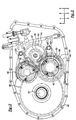
- transaxle 10 is shown to include a housing 12 within which an input shaft 14 is rotatably supported by bearings 16 and 18 for rotation about a first axis "A".
- input shaft 14 is adapted to be driven through a suitable manually-released clutch (not shown) by the vehicles's engine.
- Transaxle 10 is also shown to include a first intermediate shaft 20 rotatably supported in housing 12 by bearings 22 and 24 for rotation about second axis "B", a second intermediate shaft 26 rotatably supported in housing 12 by bearings 28 and 30 for rotation about a third axis "C”, and a final drive assembly 32 supported in housing 12 by bearings 34 and 36 for rotation about a fourth axis "D".
- final drive assembly 32 includes a differential 33 having a pair of axially-aligned side gears 38 to which axle half-shafts 40 are fixed so as to connect differential 33 to the driving wheels of the motor vehicle.
- Drive torque is supplied to differential 33 via a final drive gear 42 fixed to a differential case 44 and which is in constant meshed engagement with a first transfer gear 46 fixed to first intermediate shaft 20 as well as with a second transfer gear 48 fixed to second intermediate shaft 26.
- transfer gears 46 and 48 are "overhung" with respect to bearing assemblies 22 and 28, respectively. It will be appreciated that FIG.
- FIG. 1 is a so-called "unrolled" sectional view wherein shafts 14, 20, 26 and 40 are all arranged in a single plane.
- these shafts are compactly arranged parallel to each other, with no three thereof in a common plane, as shown in FIG. 2. In this manner, the center distance between the shafts can be effectively minimized.
- Transaxle 10 includes a series of constant-mesh gearsets 50, 52, 54, 56, 58 and 60 that can be selectively engaged for establishing six forward speed ratios between input shaft 14 and final drive gear 42.
- Gearset 50 includes a first input gear 62 fixed to input shaft 14 and a first speed gear 64 rotatably supported on first intermediate shaft 20.
- First speed gear 64 is in constant mesh with first input gear 62 for defining a first power transmission path that can be selectively engaged to establish a first forward speed ratio.
- Gearset 52 includes a second input gear 66 fixed to input shaft 14 that is in constant mesh with a second speed gear 68 rotatably supported on first intermediate shaft 20.
- gearset 52 functions to define a second power transmission path that can be selectively engaged to establish a second forward speed ratio.
- Gearset 54 includes a third input gear 70 fixed to input shaft 14 that is in constant mesh with a third speed gear 72 rotatably supported on second intermediate shaft 26. As such, gearset 54 functions to define a third power transmission path that can be selectively engaged to establish a third forward speed ratio.
- Gearset 56 includes a fourth input gear 74 fixed to input shaft 14 that is in constant mesh with a fourth speed gear 76 rotatably supported on second intermediate shaft 26. Thus, gearset 56 functions to define a fourth power transmission path that can be selectively engaged to establish a fourth forward speed ratio.
- Gearset 58 includes a fifth speed gear 78 rotatably supported on first intermediate shaft 20 which is meshed with third input gear 70.
- gearset 58 functions to define a fifth power transmission path that can be selectively engaged to establish a fifth forward speed ratio.
- Gearset 60 includes a sixth speed gear 80 rotatably supported on first intermediate shaft 20 that is meshed with fourth input gear 76.
- Gearset 60 defines a sixth power transmission path that can be selectively engaged to establish a sixth forward speed ratio.
- third input gear 70 and fourth input gear 74 are attached to or integrally formed on a stub shaft 82 to define a compound gear 84.
- Stub shaft 82 is fixed (i.e., splined) to input shaft 14.
- transaxle 10 further includes a constant-mesh reverse gearset for establishing a reverse speed ratio which includes a reverse gear 86 rotatably supported on second intermediate shaft 26 and which is in constant mesh with first speed gear 64.
- the reverse gearset defines a seventh power transmission path that can be selectively engaged to establish the reverse gear ratio.
- the six forward speed ratios are sequential with the number of teeth for each gear component listed in the following table: Gear Component Number of Teeth final drive gear 42 111 first transfer gear 46 27 second transfer gear 48 17 first input gear 62 23 first speed gear 64 71 second input gear 66 33 second speed gear 68 62 third input gear 70 53 third speed gear 72 41 fourth input gear 74 57 fourth speed gear 76 34 fifth speed gear 78 40 sixth speed gear 80 35 reverse gear 86 48
- the meshed gearsets can be selected to provide alternative gear ratios required for a different transmission application.
- each gearset is associated with a synchronizer clutch.
- a first synchronizer clutch 88 is operably located between first and second speed gears 64 and 68 and includes a hub 90 fixed to first intermediate shaft 20, a shift sleeve 92 mounted for rotation with and axial sliding movement on hub 86, and a pair of suitable synchronizers 94 interposed between shift sleeve 92 and speed gears 64 and 68.
- First synchronizer clutch 88 is of the double-acting variety such that axial movement of shift sleeve 92 in a first direction from its centered neutral position shown is adapted to couple first speed gear 64 to first intermediate shaft 20 for establishing the first forward speed ratio in which first transfer gear 46 drives final drive gear 42. Moreover, axial movement of shift sleeve 92 in the opposite direction from its neutral position is adapted to couple second speed gear 68 to first intermediate shaft 20 such that first transfer gear 46 drives final drive gear 42 at the second forward speed ratio.
- a second synchronizer clutch 96 is located between third and fourth speed gears 72 and 76 and includes a hub 98 fixed to second intermediate shaft 26, a shift sleeve 100 mounted for rotation with and axial sliding movement on hub 98, and a pair of synchronizers 102 interposed between shift sleeve 96 and third and fourth speed gears 72 and 76.
- Second synchronizer clutch 96 is of the double-acting type such that axial movement of shift sleeve 100 in a first direction from its neutral centered position shown is adapted to couple clutch gear 104 and third speed gear 72 to second intermediate shaft 26 such that second transfer gear 48 drives final drive gear 42 at the third forward speed ratio. Moreover, axial movement of shift sleeve 100 on the opposite direction from its centered neutral position is adapted to couple clutch gear 106 and fourth speed gear 76 to second intermediate shaft 26 such that second transfer gear 48 drives final drive gear 42 at the fourth speed ratio.
- the fifth and sixth forward speed ratios are established via a third synchronizer clutch 110, again of the double-acting variety, that is located between fifth speed gear 78 and sixth speed gear 80.
- Synchronizer clutch 110 includes a hub 112 fixed to first intermediate shaft 20, a shift sleeve 114 mounted for rotation with and axial sliding movement on hub 112, and a pair of synchronizers 116 interposed between shift sleeve 114, a clutch gear 118 fixed to fifth speed gear 78 and a clutch gear 120 fixed to sixth speed gear 80.
- Sliding movement of shift sleeve 114 in a first direction from its centered neutral position shown is adapted to couple clutch gear 118 and fifth speed gear 78 to first intermediate shaft 20 such that first transfer gear 46 drives final drive gear 42 at the fifth speed ratio.
- sliding movement of shift sleeve 114 in the opposite direction from its neutral position couples clutch gear 120 and sixth speed gear 80 to first intermediate shaft 20 such that first transfer gear 46 drives final drive gear 42 at the sixth forward speed ratio.
- the reverse speed ratio is established via a fourth synchronizer clutch 122 which includes a hub 124 fixed to second intermediate shaft 26, a shift sleeve 126 mounted for rotation with and sliding movement on hub 124, and a synchronizer 128 positioned between shift sleeve 126 and a clutch gear 130 fixed to reverse gear 86.
- Sliding movement of shift sleeve 126 from the neutral position shown is adapted to couple reverse gear 86 to second intermediate shaft 26 such that second transfer gear 48 drives final drive gear 42 at the reverse speed ratio and in the opposite direction with respect to the direction of rotation of final drive gear 42 effected during forward operation.
- This reversal of direction results from reverse gear 82 being driven by first speed gear 64 which, in turn, is driven by first input gear 62.
- first forward gear torque is delivered from input shaft 14 to differential 32 through elements 62, 64, 92, 90, 20, 46 and 42.
- second forward gear torque is delivered from input shaft 14 to differential 32 through elements 66, 68, 92, 90, 20, 46 and 42.
- third forward gear torque is delivered from input shaft 14 to differential 32 through elements 82, 70, 72, 100, 98, 26, 48 and 42.
- fourth forward gear torque is delivered from input shaft 14 to differential 32 through elements 82, 74, 76, 100, 98, 26, 48 and 42.
- torque is delivered from input shaft 14 to differential 32 through elements 82, 70, 78, 114, 112, 20, 46 and 42.
- torque is delivered from input shaft 14 to differential 32 through elements 82, 74, 80, 114, 112, 20, 46 and 42.
- torque is delivered from input shaft 14 to differential 32 through elements 62, 64, 86, 126, 124, 26, 48, and 42.
- FIG. 2 is a schematic illustration of the arrangement of shafts 14, 20, 26 and 40 and of the meshing of the various gearsets.
- a shift pattern or gate diagram for transaxle 10 is shown in FIG. 3.
- any suitable shift system causing coordinated movement of shift sleeves 92, 100, 114 and 126 in response to movement of a gearshift lever (not shown) to establish the various forward and reverse gears can be used with transaxle 10.
Landscapes
- Engineering & Computer Science (AREA)
- General Engineering & Computer Science (AREA)
- Mechanical Engineering (AREA)
- Structure Of Transmissions (AREA)
- Arrangement And Driving Of Transmission Devices (AREA)
- Gear-Shifting Mechanisms (AREA)
- Arrangement Or Mounting Of Control Devices For Change-Speed Gearing (AREA)
- Seal Device For Vehicle (AREA)
Applications Claiming Priority (2)
| Application Number | Priority Date | Filing Date | Title |
|---|---|---|---|
| US260532 | 1981-05-04 | ||
| US09/260,532 US6067870A (en) | 1999-02-26 | 1999-02-26 | Manual transaxle |
Publications (3)
| Publication Number | Publication Date |
|---|---|
| EP1031762A2 true EP1031762A2 (fr) | 2000-08-30 |
| EP1031762A3 EP1031762A3 (fr) | 2001-08-08 |
| EP1031762B1 EP1031762B1 (fr) | 2003-08-27 |
Family
ID=22989548
Family Applications (1)
| Application Number | Title | Priority Date | Filing Date |
|---|---|---|---|
| EP00103972A Expired - Lifetime EP1031762B1 (fr) | 1999-02-26 | 2000-02-25 | Boite-pont manuelle |
Country Status (5)
| Country | Link |
|---|---|
| US (1) | US6067870A (fr) |
| EP (1) | EP1031762B1 (fr) |
| AT (1) | ATE248303T1 (fr) |
| CA (1) | CA2299221A1 (fr) |
| DE (1) | DE60004717T2 (fr) |
Cited By (2)
| Publication number | Priority date | Publication date | Assignee | Title |
|---|---|---|---|---|
| DE10323721A1 (de) * | 2003-05-24 | 2004-12-23 | Daimlerchrysler Ag | Dreiwellen-Getriebe |
| CN103615503A (zh) * | 2013-11-26 | 2014-03-05 | 绍兴前进齿轮箱有限公司 | 一种用于捆草机的齿轮箱 |
Families Citing this family (11)
| Publication number | Priority date | Publication date | Assignee | Title |
|---|---|---|---|---|
| US6397692B1 (en) * | 2000-02-18 | 2002-06-04 | Daimlerchrysler Corporation | Electro-mechanical automatic transmission for front wheel drive |
| JP4053206B2 (ja) * | 2000-03-30 | 2008-02-27 | アイシン・エーアイ株式会社 | 手動変速機 |
| US6422103B1 (en) | 2000-06-26 | 2002-07-23 | New Venture Gear, Inc. | Compact front wheel drive six-speed transaxle |
| US20040071538A1 (en) * | 2002-10-11 | 2004-04-15 | Musfeldt Donald Edward | EZ-DZ motorized log dolly |
| DE10302258A1 (de) * | 2003-01-22 | 2004-08-12 | Zf Friedrichshafen Ag | Schaltgetriebe für ein Kraftfahrzeug |
| DE102004056936B4 (de) * | 2004-11-23 | 2011-02-03 | Getrag Getriebe- Und Zahnradfabrik Hermann Hagenmeyer Gmbh & Cie Kg | Stufenwechselgetriebe für ein Kraftfahrzeug |
| FR2886702B1 (fr) * | 2005-06-01 | 2008-12-19 | Renault Sas | Boite de vitesse a double embrayage |
| GB0516726D0 (en) * | 2005-08-15 | 2005-09-21 | Ricardo Uk Ltd | Twin layshaft transmission |
| EP2602510B1 (fr) * | 2011-12-07 | 2014-12-03 | C.R.F. Società Consortile per Azioni | Boîte de vitesses pour véhicule à moteur |
| US10889173B2 (en) * | 2018-09-19 | 2021-01-12 | Textron Inc. | Powertrain |
| US10589623B1 (en) * | 2018-09-19 | 2020-03-17 | Textron Innovations Inc. | Floating engine powertrain |
Citations (3)
| Publication number | Priority date | Publication date | Assignee | Title |
|---|---|---|---|---|
| US4738150A (en) | 1982-08-09 | 1988-04-19 | Borg-Warner Corporation | Compact manual transaxle transmission |
| US5697250A (en) | 1996-07-22 | 1997-12-16 | New Venture Gear, Inc. | Compact manual transaxle |
| US5704247A (en) | 1996-07-22 | 1998-01-06 | New Venture Gear, Inc. | Compact manual transaxle for motor vehicles |
Family Cites Families (13)
| Publication number | Priority date | Publication date | Assignee | Title |
|---|---|---|---|---|
| DE2736929C3 (de) * | 1977-08-16 | 1981-04-02 | Zahnradfabrik Friedrichshafen Ag, 7990 Friedrichshafen | Schaltbares Stirnradgetriebe |
| US4273007A (en) * | 1978-04-21 | 1981-06-16 | Kubota, Ltd. | Transmission for agricultural tractor |
| US4463622A (en) * | 1980-01-11 | 1984-08-07 | Deere & Company | Transmission and reverse gear synchronizing therefor |
| US4398432A (en) * | 1980-12-22 | 1983-08-16 | Allis-Chalmers Corporation | Transmission with overrunning clutches |
| GB8313910D0 (en) * | 1983-05-19 | 1983-06-22 | Eaton Ltd | Gearbox ratio changer |
| WO1990010806A1 (fr) * | 1989-03-16 | 1990-09-20 | Zahnradfabrik Friedrichshafen Ag | Disposition d'un train d'engrenages dans un carter general de boite de vitesses |
| DE4136455C2 (de) * | 1991-11-06 | 1997-02-27 | Getrag Getriebe Zahnrad | Sechsgang-Zahnradwechselgetriebe |
| US5346442A (en) * | 1992-08-19 | 1994-09-13 | New Venture Gear, Inc. | Range shift arrangement for four-wheel drive vehicles |
| US5385064A (en) * | 1992-10-23 | 1995-01-31 | Borg-Warner Automotive, Inc. | Dual clutch countershaft automatic transmission |
| US5816101A (en) * | 1996-08-13 | 1998-10-06 | Weston; Bevan | Transmission and shift mechanism |
| US5743141A (en) * | 1996-10-04 | 1998-04-28 | New Venture Gear, Inc. | Compact transaxle |
| US5735175A (en) * | 1996-10-18 | 1998-04-07 | New Venture Gear, Inc. | Multi-speed manual transaxle |
| US5845531A (en) * | 1997-03-18 | 1998-12-08 | New Venture Gear, Inc. | Multi-speed manual transmission with reverse brake |
-
1999
- 1999-02-26 US US09/260,532 patent/US6067870A/en not_active Expired - Fee Related
-
2000
- 2000-02-24 CA CA002299221A patent/CA2299221A1/fr not_active Abandoned
- 2000-02-25 AT AT00103972T patent/ATE248303T1/de not_active IP Right Cessation
- 2000-02-25 EP EP00103972A patent/EP1031762B1/fr not_active Expired - Lifetime
- 2000-02-25 DE DE60004717T patent/DE60004717T2/de not_active Expired - Lifetime
Patent Citations (3)
| Publication number | Priority date | Publication date | Assignee | Title |
|---|---|---|---|---|
| US4738150A (en) | 1982-08-09 | 1988-04-19 | Borg-Warner Corporation | Compact manual transaxle transmission |
| US5697250A (en) | 1996-07-22 | 1997-12-16 | New Venture Gear, Inc. | Compact manual transaxle |
| US5704247A (en) | 1996-07-22 | 1998-01-06 | New Venture Gear, Inc. | Compact manual transaxle for motor vehicles |
Cited By (2)
| Publication number | Priority date | Publication date | Assignee | Title |
|---|---|---|---|---|
| DE10323721A1 (de) * | 2003-05-24 | 2004-12-23 | Daimlerchrysler Ag | Dreiwellen-Getriebe |
| CN103615503A (zh) * | 2013-11-26 | 2014-03-05 | 绍兴前进齿轮箱有限公司 | 一种用于捆草机的齿轮箱 |
Also Published As
| Publication number | Publication date |
|---|---|
| CA2299221A1 (fr) | 2000-08-26 |
| DE60004717D1 (de) | 2003-10-02 |
| US6067870A (en) | 2000-05-30 |
| DE60004717T2 (de) | 2004-07-08 |
| EP1031762B1 (fr) | 2003-08-27 |
| ATE248303T1 (de) | 2003-09-15 |
| EP1031762A3 (fr) | 2001-08-08 |
Similar Documents
| Publication | Publication Date | Title |
|---|---|---|
| JP2520353B2 (ja) | 自動車用変速機 | |
| US7077025B2 (en) | Dual clutch automatic transaxle | |
| US5722291A (en) | Manual transmission with synchronized reverse gear | |
| US5704247A (en) | Compact manual transaxle for motor vehicles | |
| US20110011194A1 (en) | Reverse chain drive for motor vehicle transmissions | |
| US8479604B2 (en) | Powertrain for an automotive vehicle with multiple-ratio gearing and a dual power input clutch | |
| US6067870A (en) | Manual transaxle | |
| EP0837263B1 (fr) | Boíte de vitesses à plusieurs rapports à commande manuelle | |
| CA1061603A (fr) | Transmission manuelle compacte pour moteur transversal | |
| US5697250A (en) | Compact manual transaxle | |
| EP1120587A1 (fr) | Boíte de vitesses modulaire pour automobile | |
| US5743141A (en) | Compact transaxle | |
| EP1062436B1 (fr) | Boite-pont manuelle a six vitesses | |
| US6378391B2 (en) | Compact front wheel drive six-speed transaxle | |
| US5983741A (en) | Reverse gear assembly of a transmission | |
| MXPA97005531A (es) | Eje de transmision manual compacto | |
| JPH04302749A (ja) | 変速機 | |
| JPH03117749A (ja) | 変速装置 | |
| JPH0535289B2 (fr) | ||
| CN114585833A (zh) | 成组变速器装置、尤其是分流式变速器 | |
| JPH02134439A (ja) | 歯車変速機 |
Legal Events
| Date | Code | Title | Description |
|---|---|---|---|
| PUAI | Public reference made under article 153(3) epc to a published international application that has entered the european phase |
Free format text: ORIGINAL CODE: 0009012 |
|
| AK | Designated contracting states |
Kind code of ref document: A2 Designated state(s): AT BE CH CY DE DK ES FI FR GB GR IE IT LI LU MC NL PT SE |
|
| AX | Request for extension of the european patent |
Free format text: AL;LT;LV;MK;RO;SI |
|
| PUAL | Search report despatched |
Free format text: ORIGINAL CODE: 0009013 |
|
| AK | Designated contracting states |
Kind code of ref document: A3 Designated state(s): AT BE CH CY DE DK ES FI FR GB GR IE IT LI LU MC NL PT SE |
|
| AX | Request for extension of the european patent |
Free format text: AL;LT;LV;MK;RO;SI |
|
| 17P | Request for examination filed |
Effective date: 20020205 |
|
| AKX | Designation fees paid |
Free format text: AT BE CH CY DE DK ES FI FR GB GR IE IT LI LU MC NL PT SE |
|
| 17Q | First examination report despatched |
Effective date: 20020325 |
|
| GRAH | Despatch of communication of intention to grant a patent |
Free format text: ORIGINAL CODE: EPIDOS IGRA |
|
| GRAS | Grant fee paid |
Free format text: ORIGINAL CODE: EPIDOSNIGR3 |
|
| GRAA | (expected) grant |
Free format text: ORIGINAL CODE: 0009210 |
|
| AK | Designated contracting states |
Designated state(s): AT BE CH CY DE DK ES FI FR GB GR IE IT LI LU MC NL PT SE |
|
| PG25 | Lapsed in a contracting state [announced via postgrant information from national office to epo] |
Ref country code: BE Free format text: LAPSE BECAUSE OF FAILURE TO SUBMIT A TRANSLATION OF THE DESCRIPTION OR TO PAY THE FEE WITHIN THE PRESCRIBED TIME-LIMIT Effective date: 20030827 Ref country code: IT Free format text: LAPSE BECAUSE OF FAILURE TO SUBMIT A TRANSLATION OF THE DESCRIPTION OR TO PAY THE FEE WITHIN THE PRESCRIBED TIME-LIMIT;WARNING: LAPSES OF ITALIAN PATENTS WITH EFFECTIVE DATE BEFORE 2007 MAY HAVE OCCURRED AT ANY TIME BEFORE 2007. THE CORRECT EFFECTIVE DATE MAY BE DIFFERENT FROM THE ONE RECORDED. Effective date: 20030827 Ref country code: AT Free format text: LAPSE BECAUSE OF FAILURE TO SUBMIT A TRANSLATION OF THE DESCRIPTION OR TO PAY THE FEE WITHIN THE PRESCRIBED TIME-LIMIT Effective date: 20030827 Ref country code: CY Free format text: LAPSE BECAUSE OF FAILURE TO SUBMIT A TRANSLATION OF THE DESCRIPTION OR TO PAY THE FEE WITHIN THE PRESCRIBED TIME-LIMIT Effective date: 20030827 Ref country code: FI Free format text: LAPSE BECAUSE OF FAILURE TO SUBMIT A TRANSLATION OF THE DESCRIPTION OR TO PAY THE FEE WITHIN THE PRESCRIBED TIME-LIMIT Effective date: 20030827 Ref country code: CH Free format text: LAPSE BECAUSE OF FAILURE TO SUBMIT A TRANSLATION OF THE DESCRIPTION OR TO PAY THE FEE WITHIN THE PRESCRIBED TIME-LIMIT Effective date: 20030827 Ref country code: NL Free format text: LAPSE BECAUSE OF FAILURE TO SUBMIT A TRANSLATION OF THE DESCRIPTION OR TO PAY THE FEE WITHIN THE PRESCRIBED TIME-LIMIT Effective date: 20030827 Ref country code: LI Free format text: LAPSE BECAUSE OF FAILURE TO SUBMIT A TRANSLATION OF THE DESCRIPTION OR TO PAY THE FEE WITHIN THE PRESCRIBED TIME-LIMIT Effective date: 20030827 |
|
| REG | Reference to a national code |
Ref country code: GB Ref legal event code: FG4D |
|
| REG | Reference to a national code |
Ref country code: CH Ref legal event code: EP |
|
| REG | Reference to a national code |
Ref country code: IE Ref legal event code: FG4D |
|
| REF | Corresponds to: |
Ref document number: 60004717 Country of ref document: DE Date of ref document: 20031002 Kind code of ref document: P |
|
| PG25 | Lapsed in a contracting state [announced via postgrant information from national office to epo] |
Ref country code: DK Free format text: LAPSE BECAUSE OF FAILURE TO SUBMIT A TRANSLATION OF THE DESCRIPTION OR TO PAY THE FEE WITHIN THE PRESCRIBED TIME-LIMIT Effective date: 20031127 Ref country code: GR Free format text: LAPSE BECAUSE OF FAILURE TO SUBMIT A TRANSLATION OF THE DESCRIPTION OR TO PAY THE FEE WITHIN THE PRESCRIBED TIME-LIMIT Effective date: 20031127 Ref country code: SE Free format text: LAPSE BECAUSE OF FAILURE TO SUBMIT A TRANSLATION OF THE DESCRIPTION OR TO PAY THE FEE WITHIN THE PRESCRIBED TIME-LIMIT Effective date: 20031127 |
|
| PG25 | Lapsed in a contracting state [announced via postgrant information from national office to epo] |
Ref country code: ES Free format text: LAPSE BECAUSE OF FAILURE TO SUBMIT A TRANSLATION OF THE DESCRIPTION OR TO PAY THE FEE WITHIN THE PRESCRIBED TIME-LIMIT Effective date: 20031208 |
|
| PG25 | Lapsed in a contracting state [announced via postgrant information from national office to epo] |
Ref country code: PT Free format text: LAPSE BECAUSE OF FAILURE TO SUBMIT A TRANSLATION OF THE DESCRIPTION OR TO PAY THE FEE WITHIN THE PRESCRIBED TIME-LIMIT Effective date: 20040127 |
|
| NLV1 | Nl: lapsed or annulled due to failure to fulfill the requirements of art. 29p and 29m of the patents act | ||
| PG25 | Lapsed in a contracting state [announced via postgrant information from national office to epo] |
Ref country code: LU Free format text: LAPSE BECAUSE OF NON-PAYMENT OF DUE FEES Effective date: 20040225 Ref country code: IE Free format text: LAPSE BECAUSE OF NON-PAYMENT OF DUE FEES Effective date: 20040225 |
|
| PG25 | Lapsed in a contracting state [announced via postgrant information from national office to epo] |
Ref country code: MC Free format text: LAPSE BECAUSE OF NON-PAYMENT OF DUE FEES Effective date: 20040228 |
|
| REG | Reference to a national code |
Ref country code: CH Ref legal event code: PL |
|
| ET | Fr: translation filed | ||
| PLBE | No opposition filed within time limit |
Free format text: ORIGINAL CODE: 0009261 |
|
| STAA | Information on the status of an ep patent application or granted ep patent |
Free format text: STATUS: NO OPPOSITION FILED WITHIN TIME LIMIT |
|
| 26N | No opposition filed |
Effective date: 20040528 |
|
| REG | Reference to a national code |
Ref country code: IE Ref legal event code: MM4A |
|
| PGFP | Annual fee paid to national office [announced via postgrant information from national office to epo] |
Ref country code: FR Payment date: 20050202 Year of fee payment: 6 |
|
| REG | Reference to a national code |
Ref country code: FR Ref legal event code: ST Effective date: 20061031 |
|
| PG25 | Lapsed in a contracting state [announced via postgrant information from national office to epo] |
Ref country code: FR Free format text: LAPSE BECAUSE OF NON-PAYMENT OF DUE FEES Effective date: 20060228 |
|
| PGFP | Annual fee paid to national office [announced via postgrant information from national office to epo] |
Ref country code: GB Payment date: 20080220 Year of fee payment: 9 |
|
| GBPC | Gb: european patent ceased through non-payment of renewal fee |
Effective date: 20090225 |
|
| PG25 | Lapsed in a contracting state [announced via postgrant information from national office to epo] |
Ref country code: GB Free format text: LAPSE BECAUSE OF NON-PAYMENT OF DUE FEES Effective date: 20090225 |
|
| REG | Reference to a national code |
Ref country code: DE Ref legal event code: R082 Ref document number: 60004717 Country of ref document: DE Representative=s name: SCHAUMBURG & PARTNER PATENTANWAELTE GBR, DE Ref country code: DE Ref legal event code: R082 Ref document number: 60004717 Country of ref document: DE Representative=s name: SCHAUMBURG & PARTNER PATENTANWAELTE MBB, DE Ref country code: DE Ref legal event code: R082 Ref document number: 60004717 Country of ref document: DE Representative=s name: SCHAUMBURG UND PARTNER PATENTANWAELTE MBB, DE |
|
| PGFP | Annual fee paid to national office [announced via postgrant information from national office to epo] |
Ref country code: DE Payment date: 20170222 Year of fee payment: 18 |
|
| REG | Reference to a national code |
Ref country code: DE Ref legal event code: R119 Ref document number: 60004717 Country of ref document: DE |
|
| PG25 | Lapsed in a contracting state [announced via postgrant information from national office to epo] |
Ref country code: DE Free format text: LAPSE BECAUSE OF NON-PAYMENT OF DUE FEES Effective date: 20180901 |