EP1031680B1 - Gelenkige paraseismische elastoplastische Vorrichtung für Hoch- und Tiefbau und Brücke mit einer derartigen Vorrichtung - Google Patents
Gelenkige paraseismische elastoplastische Vorrichtung für Hoch- und Tiefbau und Brücke mit einer derartigen Vorrichtung Download PDFInfo
- Publication number
- EP1031680B1 EP1031680B1 EP99400478A EP99400478A EP1031680B1 EP 1031680 B1 EP1031680 B1 EP 1031680B1 EP 99400478 A EP99400478 A EP 99400478A EP 99400478 A EP99400478 A EP 99400478A EP 1031680 B1 EP1031680 B1 EP 1031680B1
- Authority
- EP
- European Patent Office
- Prior art keywords
- connecting rod
- bridge
- articulated
- plastic deformation
- respect
- Prior art date
- Legal status (The legal status is an assumption and is not a legal conclusion. Google has not performed a legal analysis and makes no representation as to the accuracy of the status listed.)
- Expired - Lifetime
Links
Images


Classifications
-
- E—FIXED CONSTRUCTIONS
- E04—BUILDING
- E04H—BUILDINGS OR LIKE STRUCTURES FOR PARTICULAR PURPOSES; SWIMMING OR SPLASH BATHS OR POOLS; MASTS; FENCING; TENTS OR CANOPIES, IN GENERAL
- E04H9/00—Buildings, groups of buildings or shelters adapted to withstand or provide protection against abnormal external influences, e.g. war-like action, earthquake or extreme climate
- E04H9/02—Buildings, groups of buildings or shelters adapted to withstand or provide protection against abnormal external influences, e.g. war-like action, earthquake or extreme climate withstanding earthquake or sinking of ground
- E04H9/021—Bearing, supporting or connecting constructions specially adapted for such buildings
- E04H9/0235—Anti-seismic devices with hydraulic or pneumatic damping
Definitions
- the invention relates to a device for limiting the amplitude of the relative displacement of two civil engineering structure elements placed under when this structure is subjected to intense solicitation mechanical.
- This mechanical stress can be linked, for example, directly or indirectly to seismic waves or weather phenomena such as hurricanes, storms, tornadoes.
- the invention relates more specifically but not exclusively to cable-stayed bridges, the device according to the invention can easily be place during the construction of the bridge or during the reinforcement of a bridge former.
- the device according to the invention when it is set up for a bridge such as a cable-stayed bridge also makes it possible to limit the movements due to the wind and to ensure proper functioning of the road joints located at ends of the work.
- the macroscopic MSI scale correlates the amplitude of the earthquakes to the destruction of buildings.
- seismic devices in which a part of the mechanical energy resulting from the solicitation to which the civil engineering structure, is absorbed by plastic deformation of a part the device provided for this purpose.
- US-A-3,963,099 discloses an earthquake-resistant device hysteresis.
- a beam is rigidly fixed to the foundations, elements of guiding in contact with the beam before its deformation being deformed with beam.
- This beam may be of cylindrical section or prismatic three or more than three sides.
- the guide bars are thick from 0.5 to 1 times the thickness of the beam and are about 33% higher than the total height of this beam.
- a cylindrical head is attached to the upper end of the beam, this head being placed in a cylinder attached to the building.
- the maximum rotation of the beam is of the order of 15 °.
- the parts plastically deformable can deform uncontrollably, when placed in such complex stress fields than those related to earthquakes.
- the seismic device described in this document FR-A-2 756 581 comprises means for guiding the plastic deformation of means deformable such as a beam connecting two parts of an engineering structure likely to move relative to one another during earthquakes.
- This earthquake-resistant device has the characteristics of the preamble of the claim 1.
- the invention relates to a seismic device comprising means plastically deformable in a controlled manner, these means having inertia and geometries adapted to the mechanical demands exceptional situations such as those encountered during earthquakes more common solicitations such as those related to the wind.
- the invention relates more particularly but not exclusively to bridges with shrouds.
- the stays can be arranged parallel to each other (guying in harp) or radiating from the head of pylons (fan-like guying).
- the stays can form a central layer or two lateral layers.
- Cable-stayed bridges are tall structures with only a small number of points of support, namely the pylons and some ancillary batteries.
- the apron can oscillate in case of earthquakes like a swing of which movements are disconnected from the supporting structure or in any case to completely different eigenfrequencies.
- the device according to the invention makes it possible to limit these oscillations all in ensuring smooth operation of the end-face joints of the structure and the safety of the traffic, including in case of strong winds.
- the invention relates to a seismic device comprising connecting means for connecting two pieces mobile and limit the relative movement of these two moving parts one by report to the other.
- These connecting means comprise a beam capable of undergoing plastic deformation during the relative displacement of the moving parts one relative to each other and means for guiding the plastic deformation of the beam, these guide means being attachable to any of the moving parts.
- the connecting means also comprise a connecting rod, one of which first end is articulated around a first axis to an extreme part of the beam and a second end of which is arranged to allow said rod to be articulated to the other movable piece about a second axis substantially parallel to the first axis.
- Figure 1 is an elevational view of a guyed cable bridge.
- the invention is in no way limited to the field technical particularity of cable-stayed bridged or suspended bridges, but can be implemented in any type of bridge and generally in any type of civil engineering structure in which two elements of structure are likely to be moving away from each other under the effect of seismic waves and / or more usual stresses such as those related to the wind for example.
- the heights of the pylons have also increased, exceeding 200 m today, with a weight of more than 20,000 tonnes per pylon.
- FIG. 1 represents an elevational view of a cable-stayed bridge symmetrical to three bays, including two pylons.
- the deck 1 of the bridge may be metallic or prestressed concrete, with a box constant height or not, solid or open slab.
- the apron can, in other embodiments, be mixed and understand metal caissons and a slab of reinforced concrete, the caissons having a section for example trapezoidal.
- the bank spans 2,3 do not rely on intermediate stacks but may have pilettes, the stays 4 fixed on these pilets playing the role of restraint stays.
- the stays 4 can be made from parallel wire cables, cables formed of parallel strands or closed cables.
- parallel wire cables is conventionally meant drawn wire assemblies in high-strength steels, placed in polyethylene or metal tubes, wax, grease or grout cement filling the empty space between the wires, after tensioning.
- “Closed cables” conventionally refers to bundles of wires parallel to circular section surrounded by section wire crowns trapezoidal and Z-shaped wires.
- the strands can be of the type of those used in prestressing.
- the stays can be stretched between two points of the deck located from and else of a pylon or between a point of the apron and a point of the pylon.
- rigid metal tubes constituting stool support are then provided in the upper zone of the pylons when the guy cables are arranged in a semi-fan and cross the pylons.
- the stays 4 are in harp and secondary cables, called “needles” 4 'connect the shrouds together in particular to limit the risks of resonant vibrations of shrouds under the effect of wind.
- the suspension of the apron can be lateral, ie the apron can be supported by two lateral sheets of shrouds, the pylons 5 including two masts.
- the suspension of apron can be axial, pylons having a shape of A surmounted by a barrel vertical, for example.
- the pylons in the illustrated embodiment, include two inclined legs 6.7 joined by a vertical shaft 8 in part higher.
- the masts 6.7 have a basal portion 9.10 below a spacer 11, this basal portion 9,10 being inclined at an angle ⁇ of the order of 5 to 30 ° about the vertical, the two basal parts converging on one to others at their lower end.
- the towers have substantially a form of H, the stays being arranged in two layers side, the basal portions below the spacer being inclined relative to the vertical, at an angle of about 5 to 20 ° and diverging from each other at their lower end.
- top parts 110, 12 of the legs 6.7, above the spacer 11, are inclined at an angle ⁇ with respect to the vertical, this angle ⁇ being substantially equal to the angle ⁇ defined previously, in the embodiment represent.
- the pylons have a substantially vertical plane of symmetry S, in the embodiment shown.
- this direction D1 is substantially horizontal.
- the apron comprises a curved profile whose ends are at the same level or at least a part curve and / or at least a portion with a straight but inclined profile.
- the pylons 5 are provided with seismic devices of elasto-plastic type with controlled deformation, which also makes it possible to block or limit the movements of the deck 1 under the effect of the wind or other solicitations in service.
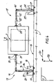
- At least one longitudinal damper 13 is disposed between the deck 1 and the least one leg 6.7 of a pylon 5.
- This longitudinal damper 13 comprises a beam 14 and a connecting rod articulated 15.
- the beam 14 is articulated in rotation, relative to the connecting rod 15, around a axis 16, substantially perpendicular to the plane T.
- the inner end portion 17 of the beam 14 is placed in a jig of bending 18, secured to the outer lateral edge 19 of the apron 1.
- the beam 14 extends at least before deformation of the shock absorber - and therefore especially during its implementation place - substantially in the direction D2 and the rod 15 extends substantially according to direction D1.
- the rod 15 is articulated in rotation, with respect to the mast 7 of the pylon 5, around an axis 20 substantially parallel to the axis 16.
- the axis 20 is connected to the part 21 secured to the mast 7.
- the rod 15 can be provided as shown, a hydraulic coupler or mechanical 22.
- this coupler 22 only deforms when the applied stress exceeds a threshold value.
- this coupler has a viscous behavior and a high sensitivity to the speed of deformation, a low rate of deformation leading for example to deformation immediate, for example to take account of the movements of the deck 1 under the effect of thermal expansion or creep, a velocity of high deformation leading to blockage of the coupler and / or dissipation of the mechanical energy by friction, at least for one certain range of constraints.
- the bending template 18 includes two bending surfaces 23,24 substantially symmetrical with respect to a median plane of the beam 14, in the embodiment shown.
- the template does not include that a curved surface guiding the plastic deformation of the beam 14.
- the template includes two curved surfaces whose radii of curvature and / or dimensions are not not identical.
- the bending surfaces 23,24 have a substantially constant radius of curvature throughout their entire length.
- the bending jig 18 thus has an opening 25 of section rectangular, flaring regularly from the inside to the outside.
- This opening 25 may, if necessary be filled with a soft product, not resistant to compression but protecting the beam 14, housed in the 18 gauge, against atmospheric aggression.
- the beam 14 may be made of metallic material, provided the case protection against corrosion.
- the beam 14 to deform plastically when the damper is strongly stressed, for example in case of earthquakes, the material used for its development should have a non-fragile behavior, the level of ductility of this material and its threshold of plasticity being chosen according to the amount of mechanical energy that we wish to absorb.
- the beam 14 can be made by assembling different materials.
- the beam 14 may have a variable inertia profile so as to allow the simultaneous lamination of all sections of the profile and thus allow efficient dissipation of mechanical energy.
- the vertical section of the beam can thus be of decreasing size regularly from the inner end of this beam to its opposite extreme part.
- the beam 14 can be formed by assembly metal plates 14a, 14b, 14c, 14d, 14e.
- Two longitudinal dampers 13 can be put in place, for each pylon leg, where appropriate on each side of each leg, that it is represented in FIG.
- the two dampers 13, 13 ' can be identical in structure and dimensions or not.
- the damper 13 ' may be devoid of hydraulic coupler or mechanical 22.
- the dampers 13, 13 ' are arranged symmetrically with respect to a median plane P of the leg 7 of a pylon 5.
- the damper 13 ' is placed at above or below the damper 13 and / or the hinge axis 16 'of the connecting rod 15 'with respect to the beam 14' is arranged more outboard or more inside that the corresponding axis 14 of the damper 13.
- a transverse damper 26 can be put in place between one leg of a pylon and the apron.
- the transverse damper 26 comprises a beam 27 and a connecting rod 28, the connecting rod 28 being hingedly mounted in rotation about an axis 29 with respect to the beam 27.
- the end portion 30 of the beam 27 opposite the hinge 29 is placed in a bending template 31 fixed on a side wall of the leg 7, the template 31 comprising two guide surfaces 32, 33 of the deformation plastic beam 27.
- the bending surfaces 32, 33 have a radius of curvature substantially constant over their entire length and are symmetrical with respect to at a median plane P 'of the beam 27.
- the jig 30 defines an opening 34 of rectangular section flaring towards the hinge axis 29.
- the surfaces of bending are not symmetrical to each other with respect to plane P 'and / or do not have a constant radius of curvature along their length.
- the template 31 may contain a soft product, not resistant at the compression but protecting the beam 27 housed in the jig 30 against atmospheric aggressions.
- the beam 27 may be made of metallic material, provided where appropriate protection against corrosion.
- the beam 27 to be deformed plastically when the damper is strongly stressed, for example during earthquakes, the material used for its development should have a non-fragile behavior, the level of ductility of this material and its threshold of plasticity being chosen according to the amount of mechanical energy that we wish to absorb.
- the beam 27 can be made from different materials.
- the beam 27 may have a variable inertia profile, so as to allow the plasticization of all sections of the profile and thus allow a efficient dissipation of mechanical energy.
- the beam 27 can be made by assembling metal plates 27a, 27b, 27c, 27d, 27e, similar to what was mentioned above for the beam 14.
- the rod 28 is articulated in rotation about an axis 35 with respect to the apron 1, a part 36 defining the axis 35 and being integral with a wall side 19 of the apron 1.
- two dampers 26, 26 ' can be provided on at least one leg of a pylon 5.
- transverse dampers can be of structure and dimensions identical or not.
- dampers 26, 26 ' are placed in symmetry with respect to the plane P defined previously.
- the rods 28, 28 ' are themselves, at least during the implementation of the shock absorbers, substantially parallel to the direction D2.
- the hinge axis 16 of the connecting rod 15 of a longitudinal damper is placed more outward than the hinge axis of the rod 28 of the transverse damper 26 placed opposite.
- the axes of articulation 16, 29 of the rods 15, 28 are substantially aligned.
- the axis 29 is placed further inside than axis 16.
- the longitudinal damper (s) 15, associated with a mast considered, may be placed above or below the shock absorber (s) transversal 26.
- the dampers are placed above and parallel to the shock absorbers transverse.
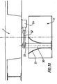
- FIGS. 8 and 9 is shown a transverse or longitudinal damper following the orientation with respect to the directions D1 and D2 of the beam 37 plastically deformable.
- the lower end 38 of the beam 37 is placed in a housing 39 of the spacer 11 of a pylon 5.
- the upper end portion 40 of the beam 37 is mounted articulated around of an axis 41 relative to a piece 42 sliding in a housing 43 of apron 1.
- spacer and the apron could be elements any of a civil engineering structure, the structure of the damper being identical to that shown.
- the housing 39 includes wedging means 44 of the extreme part lower 38 of the beam 37.
- the housing 39 comprises a deformation jig 45.
- this template 45 comprises at least two deformation guide surfaces, substantially symmetrical with respect to at a median plane P "to the beam 37, of constant radii of curvature on their length or not.
- the opening of the jig 45 is then of rectangular or square section, the gauge flaring regularly towards the apron 1.
- the jig 45 is substantially cylindrical and flares towards the apron 1 in the manner of a trumpet mouth.
- the opening of the template may contain a soft product that is not resistant to compression but protecting the beam 37 from atmospheric aggression.
- the beam 37 is, in the embodiment shown, formed by a assembly of parallel plates 37a to 37g, these plates being bolted and / or welded together by any suitable method known per se.
- the stubs 46, 47 are mounted articulated at their first end portion 48 to the spacer 11 and are integral, at their end opposite the beam 37, are directly, either by through a part surrounding the beam 37.
- bracon is used here in so far as it designates conventional a short support piece arranged obliquely, the pieces 46,47 arranged obliquely with respect to the beam 37 serving to support this one and participate in guiding its deformation.
- Slide plates 49 may be provided between the side walls extremes of the piece 42 and the housing 43 of the apron 1.
- These plates 49 may be in two parts, one of polytetrafluoroethylene PTFE secured to the slide 42, the other in stainless steel secured to the housing 43.
- the device shown in FIGS. 8 and 9 can be arranged vertically or in any other direction.
- FIGS. 8 and 9 can be place during the construction of a civil engineering structure such as a bridge to cable-stays for example, or during the reinforcement of an old structure.
- each damper may be arranged so as to be deformable in different directions, for example longitudinal example, transverse and oblique.
- a longitudinal damper in the example considered comprises a beam 50 which can be analogous beams 14,37 previously described, is placed in a template of bending 51 that can be analogous to the bending templates 18, 31, 45 previously described.
- the beam 50 is articulated in rotation to a connecting rod 52, about an axis 53.
- the connecting rod 52 is itself articulated to a hydraulic or mechanical coupler, of the type described above, this coupler 54 being integral with the deck 1.
- the damper works as a console, the articulated rod of the longitudinal damper ensuring the transmission of efforts between the deck and the pylon.
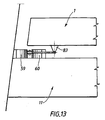
- dampers 55, 56 provided each of a plastically deformable beam 57, 58 are placed between the spacer 11 and deck 1 of the bridge.
- apron 1 and the spacer 11 could be two parts of a civil engineering structure likely to be move relative to each other under the effect for example of constraints related to earthquakes.
- Each beam 57, 58 can be plastically deformed on jigs of deformation 59, 60, 61, 62.
- the beam 58 of the longitudinal damper 56 is guided in its possible plastic deformation by two curved surfaces 63, 64 to simple radius of curvature substantially constant.
- These curved surfaces 63, 64 are substantially symmetrical with respect to a median plane to the beam 58, in the embodiment shown.
- the surfaces 63, 64 are not symmetrical to one another and / or have a radius of curvature variable from one edge 65 to the other edge 66.
- the two ends of the beam 58 are articulated in rotation around axes 67, 68 substantially parallel, with respect to two connecting rods 69, 70 respectively.
- the connecting rod 69 is itself articulated in rotation about an axis 71 relative to to a hydraulic or mechanical coupler 72, of the type similar to those defined above.
- connecting rod 70 is articulated in rotation around an axis 73 relative to to a hydraulic or mechanical coupler 74.
- the beam 58 is substantially placed in the direction D2 and the connecting rods 70, 71 are substantially parallel to the direction D1.
- the hinge pins 67, 68, 71 and 73 are then substantially parallel between them and perpendicular to the plane T.
- the beam 57 of the damper 55 is placed at the origin in the direction D1, the damper 55 then being transverse.
- This beam 57 is guided in its possible plastic deformation by two guide jigs 59, 60 comprising two single guide surfaces substantially constant curvature 75, 76, symmetrical with respect to a plane median to the beam 57, in the embodiment shown.
- the beam 57 is articulated in rotation about axes 77, 78 with respect to two connecting rods 79, 80 respectively.
- the beam 57 is substantially disposed in the direction D1 and the rods 79, 80 are substantially parallel to direction D2.
- the axes 77, 78, 81, 82 are then substantially parallel to each other and perpendicular to the plane T.
- the templates 59, 60, 61 and 62 are integral with the spacer 11 and the connecting rods 69, 70, 79, 80 are bonded to apron 1 by joints.
- the templates are the reverse integral of the deck 1 and the rods are connected to the spacer 11 by joints.
- Each pylon of the bridge may be provided with at least one assembly shown in Figures 11 to 13.
- the apron 1 is mounted integral with a pylon of the bridge, at least with respect to longitudinal stresses, the other pylons being provided with damping means.
- the dampers described above with reference three embodiments of the invention make it possible to limit the wind-related movements and to ensure proper functioning of the joints pavement at the ends of the structure, while ensuring dissipation most of the mechanical energy associated with seismic waves without irreparable damage to the structure and preserving the safety of the users.
- the invention is in no way limited to the field of but also concerns the field of suspension bridges or generally speaking, structures in which two elements of civil engineering structure are likely to be driven on the move one with respect to the other.
Claims (17)
- Erdbebensicherungs-Vorrichtung mit die Verbindung von zwei mobilen Teilen (1, 5) untereinander und die Begrenzung der relativen Verschiebung dieser beiden mobilen Teile (1, 5) im Verhältnis zueinander erlaubenden Verbindungsmitteln (13, 13', 26, 26', 55, 56), wobei diese Verbindungsmittel (13, 13', 26, 26', 55, 56) einen Balken (14, 27, 27', 50, 57, 58) umfassen, der geeignet ist, bei der relativen Verschiebung der mobilen Teile (1, 5) im Verhältnis zueinander und der Führungsmittel (18, 31, 51, 59, 60, 61, 62) der plastischen Verformung des Balkens (14, 27, 27', 50, 58) plastisch verformt zu werden, wobei diese Führungsmittel (18, 31, 51, 59, 60, 61, 62) an einem beliebigen mobilen Teil (1, 5) befestigt sein können, wobei die Vorrichtung dadurch gekennzeichnet ist, dass die Verbindungsmittel (13, 13', 26, 26', 55, 56) darüber hinaus ein Zwischenglied (15, 15', 28, 28', 69, 70, 79, 80) umfassen, von dem ein erstes Ende um eine erste Achse (16, 16', 29, 29', 53, 67, 68, 77, 78) an einem Endteil des Balkens (14, 27, 27', 50, 57, 58) artikuliert ist und von dem ein zweites Ende angeordnet ist, um dem genannten Zwischenglied (15, 15', 28, 28', 52, 69, 70, 79, 80) an dem anderen mobilen Teil (5, 1) um eine zweite, zur ersten Achse (16, 16', 29, 29', 53, 67, 68, 77, 78) deutlich parallelen Achse (20, 20', 35, 71, 73, 81, 82) artikuliert zu werden.
- Vorrichtung gemäß Anspruch 1, dadurch gekennzeichnet, dass der Balken (14, 27, 37, 50, 57, 58) und das Zwischenglied (15, 27, 52, 69, 70, 79, 80) beim Einsetzen der Vorrichtung lotrecht im Verhältnis zueinander angeordnet werden.
- Vorrichtung gemäß Anspruch 1 oder 2, dadurch gekennzeichnet, dass ein hydraulischer oder mechanischer Koppler einerseits mit dem Korpus des Zwischengliedes und andererseits mit dem mobilen Teil verbunden wird, im Verhältnis zu dem das Zwischenglied artikuliert ist.
- Vorrichtung gemäß Anspruch 1 bis 3, dadurch gekennzeichnet, dass der Balken (14, 27, 37, 50, 57, 58) aus einem aus Stählen und Metalllegierungen, Verbundmetallen mit Metallmatrix umfassenden Gruppe ausgewählten Material gebildet wird.
- Vorrichtung gemäß Anspruch 1 bis 4, dadurch gekennzeichnet, dass die Führungsmittel der plastischen Verformung wenigstens ein eine kontinuierliche oder diskontinuierliche gekrümmte Fläche definierendes mechanisches Stück umfassen, gegen die der Teil der Verbindungsmittel (14, 27, 37, 50, 57, 58) gefaltet wird, der geeignet ist, bei der genannten Verformung plastisch verformt zu werden.
- Vorrichtung gemäß Anspruch 1 bis 5, dadurch gekennzeichnet, dass der Endteil (17, 30) des nicht mit dem Zwischenglied (15, 28) verbundenen Balkens (14, 27) in eine mit einem der mobilen Teile (1, 11) fest verbundenen Krümmungs-Vorrichtung (18, 31) platziert wird.
- Vorrichtung gemäß Anspruch 1 bis 5, dadurch gekennzeichnet, dass der Teil der Verbindungsmittel, der geeignet ist, plastisch verformt zu werden, wenigstens einen Metallbalken (50) umfasst, von dem sich ein erster Endteil in einer Aufnahme eines ersten mobilen Teils (1, 11) erstreckt, wobei der zweite Endteil des genannten Balkens an einem Zwischenglied (52) artikuliert ist, der Zwischenabschnitt des genannten Balkens (50), wobei der sich zwischen dem ersten Endteil und dem Artikulationspunkt an dem genannten Zwischenglied befindet, zur Verformung frei ist, wobei die gekrümmte Führungsfläche zur plastischen Verformung sich am Ende der genannten Aufnahme des genannten mobilen Teils befindet.
- Vorrichtung gemäß Anspruch 1 bis 7, dadurch gekennzeichnet, dass der Balken (14, 27, 37, 50, 57 58) einen allgemeinen rechteckigen Querschnitt aufweist, wobei die gekrümmte Führungsfläche zur plastischen Verformung des genannten Balkens die Form eines Zylinderteils aufweist.
- Vorrichtung gemäß Anspruch 8, dadurch gekennzeichnet, dass die Führungsfläche zur plastischen Verformung durch zwei, auf jeder Seite des Balkens angeordnete und im Verhältnis zu einer medianen Ebene des genannten Balkens gekrümmte Flächen gebildet wird.
- Vorrichtung gemäß Anspruch 1 bis 7, dadurch gekennzeichnet, dass der Balken einen allgemeinen kreisrunden Querschnitt hat, wobei die gekrümmte Führungsfläche zur plastischen Verformung durch einen Abschnitt der Fläche eines zur Fläche eines Trompetentrichters analogen Torus mit deutlich mit der des Balkens zusammenfallender Symmetrieachse gebildet wird.
- Vorrichtung gemäß Anspruch 1 bis 10, dadurch gekennzeichnet, dass der erste und zweite mobile Teil (1, 11) aus Beton, aus Stahl oder analogem Material sind.
- Kunstwerk, wie zum Beispiel eine Brücke, dadurch gekennzeichnet, dass es wenigstens eine Erdbebensicherungs-Vorrichtung gemäß Definition in Anspruch 1 bis 11 umfasst.
- Kunstwerk gemäß Anspruch 12, dadurch gekennzeichnet, dass es sich um eine Schrägseilbrücke mit wenigstens einem mit einem eines der mobilen Teile bildenden Steg (11) versehenen Pylon (5) handelt, wobei die Fahrbahnplatte der Brücke das andere mobile Teil bildet.
- Brücke gemäß Anspruch 13, wobei sich ihre Fahrbahndecke gemäß einer Längsrichtung D1 erstreckt, dadurch gekennzeichnet, dass sie wenigstens eine einen länglichen Dämpfer bildende Erdbebensicherungs-Vorrichtung umfasst, wobei die genannte Vorrichtung einen plastisch verformbaren Metallbalken umfasst, dessen eines Endteil (17) in einer an der Fahrbahnplatte (1) befestigten Krümmungs-Vorrichtung (18) untergebracht ist, wobei der genannte Balken sich in Ruhestellung in einer zur Richtung D1 deutlich lotrechten Richtung D2 erstreckt und an einem sich gemäß der Richtung D1 erstreckenden Zwischenglied (15) artikuliert ist, wobei das genannte Zwischenglied selbst an einem Pylonbein der Brücke artikuliert ist.
- Brücke gemäß Anspruch 14, dadurch gekennzeichnet, dass der längliche Dämpfer mit einem den Korpus des Zwischengliedes (15) mit der Artikulationsachse (20) des genannten Zwischengliedes (15) eines Beins des Pylons (5) der Brücke verbindenden hydraulischen oder mechanischen Koppler (22) versehen ist.
- Brücke gemäß Anspruch 14 oder 15, dadurch gekennzeichnet, dass sie wenigstens zwei im Verhältnis zu einer medianen Ebene P symmetrisch zu einem Bein eines Pylons (5) angeordnete längliche Dämpfer umfasst.
- Brücke gemäß Anspruch 14 bis 16, dadurch gekennzeichnet, dass sie wenigstens eine einen transversalen Dämpfer umfassende Erdbebensicherungs-Vorrichtung umfasst, wobei die genannte Vorrichtung einen Metallbalken (27) umfasst, dessen eines erstes Endteil (30) in einer mit einem Bein des Pylons fest verbundenen Krümmungs-Vorrichtung (31) platziert ist, wobei der genannte Balken (27) gemäß der Richtung D1 angeordnet ist und an einem Zwischenglied (28) artikuliert ist, wobei das genannte Zwischenglied in Ruhestellung gemäß einer zu D1 deutlich lotrechten Richtung D2 platziert ist, wobei das genannte Zwischenglied (28) an der Fahrbahnplatte (1) im Verhältnis zu einer zur Artikulationsachse (29) des Balkens (27) im Verhältnis zum Zwischenglied (28) deutlich parallelen Achse (35) artikuliert ist.
Priority Applications (5)
| Application Number | Priority Date | Filing Date | Title |
|---|---|---|---|
| AT99400478T ATE303489T1 (de) | 1999-02-26 | 1999-02-26 | Gelenkige paraseismische elastoplastische vorrichtung für hoch- und tiefbau und brücke mit einer derartigen vorrichtung |
| EP99400478A EP1031680B1 (de) | 1999-02-26 | 1999-02-26 | Gelenkige paraseismische elastoplastische Vorrichtung für Hoch- und Tiefbau und Brücke mit einer derartigen Vorrichtung |
| DE69926984T DE69926984D1 (de) | 1999-02-26 | 1999-02-26 | Gelenkige paraseismische elastoplastische Vorrichtung für Hoch- und Tiefbau und Brücke mit einer derartigen Vorrichtung |
| JP2000050463A JP2000248508A (ja) | 1999-02-26 | 2000-02-22 | 耐震装置及び耐震装置を備えた土木構造物 |
| HK01101499A HK1032615A1 (en) | 1999-02-26 | 2001-02-28 | Articulated paraseismic elastroplastic device for civil engineering construction and bridge with such a device |
Applications Claiming Priority (1)
| Application Number | Priority Date | Filing Date | Title |
|---|---|---|---|
| EP99400478A EP1031680B1 (de) | 1999-02-26 | 1999-02-26 | Gelenkige paraseismische elastoplastische Vorrichtung für Hoch- und Tiefbau und Brücke mit einer derartigen Vorrichtung |
Publications (2)
| Publication Number | Publication Date |
|---|---|
| EP1031680A1 EP1031680A1 (de) | 2000-08-30 |
| EP1031680B1 true EP1031680B1 (de) | 2005-08-31 |
Family
ID=8241893
Family Applications (1)
| Application Number | Title | Priority Date | Filing Date |
|---|---|---|---|
| EP99400478A Expired - Lifetime EP1031680B1 (de) | 1999-02-26 | 1999-02-26 | Gelenkige paraseismische elastoplastische Vorrichtung für Hoch- und Tiefbau und Brücke mit einer derartigen Vorrichtung |
Country Status (5)
| Country | Link |
|---|---|
| EP (1) | EP1031680B1 (de) |
| JP (1) | JP2000248508A (de) |
| AT (1) | ATE303489T1 (de) |
| DE (1) | DE69926984D1 (de) |
| HK (1) | HK1032615A1 (de) |
Families Citing this family (3)
| Publication number | Priority date | Publication date | Assignee | Title |
|---|---|---|---|---|
| CN102619162B (zh) * | 2012-03-23 | 2014-09-17 | 中铁大桥勘测设计院集团有限公司 | 大跨度桥梁自平衡抗风装置 |
| CN109164041B (zh) * | 2018-10-17 | 2021-06-22 | 中国航发贵阳发动机设计研究所 | 一种高温环境下阻尼测量试验件 |
| CN111691313B (zh) * | 2020-07-09 | 2022-05-03 | 重庆交通大学 | 一种桥梁施工用组合转体支座 |
Family Cites Families (47)
| Publication number | Priority date | Publication date | Assignee | Title |
|---|---|---|---|---|
| US3963099A (en) | 1975-05-08 | 1976-06-15 | New Zealand Inventions Development Authority | Hysteretic energy absorber |
| US4269011A (en) | 1979-06-08 | 1981-05-26 | Ikonomou Aristarchos S | Earthquake guarding system |
| HU180621B (en) | 1981-01-08 | 1983-03-28 | Budapesti Mueszaki Egyetem | Shock absorber insert set |
| CA1206981A (en) | 1983-01-17 | 1986-07-02 | Edward R. Fyfe | Deflection control device |
| US4593501A (en) | 1983-10-11 | 1986-06-10 | Isosys, Inc. | Vibration and shock isolator with adjustable stiffness |
| JPS6092571A (ja) | 1983-10-27 | 1985-05-24 | 藤田 隆史 | 構造物の免震装置 |
| HU190300B (en) | 1984-05-22 | 1986-08-28 | Budapesti Mueszaki Egyetem,Hu | Device for realizing progressive amortization serving for decreasing the seizmic stress of constructions |
| US4731966A (en) | 1985-06-19 | 1988-03-22 | Takafumi Fujita | Vibration energy absorber device |
| US4830927A (en) | 1986-02-07 | 1989-05-16 | Bridgestone Corporation | Anti-seismic bearing and assembly of anti-seismic bearings |
| US4761925A (en) | 1986-03-31 | 1988-08-09 | Bridgestone Corporation | Anti-seismic rubber bearing |
| FR2625763B2 (fr) | 1986-07-21 | 1990-07-27 | Bellavista Patrice | Dispositif de construction antisismique pour batiment |
| FR2602293B1 (fr) | 1986-08-04 | 1990-08-03 | Bridgestone Corp | Dispositif antisismique |
| US4910929A (en) | 1986-08-20 | 1990-03-27 | Scholl Roger E | Added damping and stiffness elements |
| US4901486A (en) | 1987-03-06 | 1990-02-20 | Kajima Corporation | Elasto-plastic damper |
| US4991366A (en) | 1987-10-05 | 1991-02-12 | Akira Teramura | Vibration isolating device |
| US4953330A (en) | 1987-12-01 | 1990-09-04 | Mitsui Kensetsu Kabushiki Kaisha | Damping device in a structure and damping construction and damping method using those devices |
| JPH0762409B2 (ja) | 1987-12-26 | 1995-07-05 | 日本鋼管株式会社 | クーロン摩擦を利用した免震装置 |
| US5373670A (en) | 1988-05-06 | 1994-12-20 | Sumitomo Gomu Kogyo Kabushiki Kaisha | Shakeproof bearing |
| IT1229825B (it) | 1988-10-26 | 1991-09-13 | Fip Ind | Dispositivo dissipatore di energia meccanica e limitatore di carico, per il collegamento di elementi strutturali, particolarmente studiato per la protezione sismica di ponti, viadotti, edifici e simili |
| US4910930A (en) | 1988-10-28 | 1990-03-27 | Base Isolation Consultants, Inc. | Seismic isolation structure |
| FR2643105B1 (fr) | 1989-02-10 | 1995-10-13 | Bellavista Patrice | Isolateur parasismique pour la construction de batiments |
| JP2790185B2 (ja) | 1989-02-15 | 1998-08-27 | 辰治 石丸 | 差動二重梃子機構を有する構造体の免震・制振機構 |
| US5147018A (en) | 1989-03-02 | 1992-09-15 | Kajima Corporation | Cylinder lock device for use in structure |
| US4950628A (en) | 1989-04-19 | 1990-08-21 | Corning Incorporated | Material and process to produce low thermal expansion cordierite structures |
| JP2927301B2 (ja) | 1989-08-01 | 1999-07-28 | 住友ゴム工業株式会社 | 周囲拘束型免震支承 |
| JP2671904B2 (ja) | 1989-08-04 | 1997-11-05 | 鹿島建設株式会社 | ボルト型弾塑性ダンパーおよび建物の部材接合部 |
| IT1239224B (it) | 1990-02-20 | 1993-09-28 | Fip Ind | Elemento dissipatore e limitatore di carico, particolarmente studiato per dispositivi antisismici ed apparecchi di appoggio antisismici per ponti, viadotti, edifici e simili. |
| FR2660353A1 (fr) | 1990-03-30 | 1991-10-04 | Technologies Speciales Ingenie | Procedes et boucliers parasismiques. |
| IT1241781B (it) | 1990-08-30 | 1994-02-01 | Marco Carcassi | Apparecchiatura dissipativa per strutture antisismiche |
| JP2883219B2 (ja) | 1990-10-17 | 1999-04-19 | オイレス工業株式会社 | 免震支持装置 |
| US5103605A (en) | 1991-04-29 | 1992-04-14 | Sul Tae H | Earthquake resistant building support system |
| JPH086494B2 (ja) | 1991-06-07 | 1996-01-24 | 鹿島建設株式会社 | 構造物の振動制御装置 |
| JP2940223B2 (ja) * | 1991-06-14 | 1999-08-25 | 鹿島建設株式会社 | 能動制振型橋梁 |
| US5347771A (en) | 1991-06-20 | 1994-09-20 | Kajima Corporation | High damping device for seismic response controlled structure |
| JPH05141464A (ja) | 1991-11-15 | 1993-06-08 | Kajima Corp | 積層ゴム支承及び該積層ゴム支承を用いた構造物の振動制御装置 |
| JPH05141463A (ja) | 1991-11-15 | 1993-06-08 | Kajima Corp | 積層ゴム及び該積層ゴムを用いた構造物の振動制御装置 |
| JP2603391B2 (ja) | 1991-12-25 | 1997-04-23 | 鹿島建設株式会社 | 制震構造物用可変減衰装置 |
| FR2694400A1 (fr) | 1992-07-31 | 1994-02-04 | Inst Nat Polytech Grenoble | Matériau d'électrode pour capteur potentiométrique à oxygène fonctionnant à une température inférieure à 250degré C, et procédé pour son obtention. |
| FR2698400B1 (fr) | 1992-10-29 | 1995-03-03 | Sncf | "Dispositif parasismique" pour ouvrages de construction notamment pour ponts et plate-forme offshore. |
| JPH06300081A (ja) * | 1993-04-09 | 1994-10-25 | Mitsubishi Heavy Ind Ltd | 制振支持構造 |
| JPH08510539A (ja) | 1993-06-02 | 1996-11-05 | インダストリアル リサーチ リミテッド | 大型構造物のための運動ダンパ |
| US5490356A (en) | 1993-11-24 | 1996-02-13 | Mm Systems Of Arizona | Seismic isolation bearing |
| IT1270025B (it) | 1994-03-08 | 1997-04-28 | Fip Ind | Dispositivo dissipatore e limitatore di carico, particolarmente studiato per la realizzazione di opere civili o industriali ad elevataresistenza contro gli effetti sismici |
| FR2723111B1 (fr) * | 1994-07-29 | 1996-10-18 | Freyssinet Int Stup | Perfectionnements aux dispositifs de transmission d'efforts pour ouvrages de genie civil |
| US5842312A (en) | 1995-03-01 | 1998-12-01 | E*Sorb Systems | Hysteretic damping apparati and methods |
| FR2756581B1 (fr) | 1996-11-29 | 1999-01-22 | Campenon Bernard Sge | Dispositif parasismique comportant des moyens de guidage de la deformation plastique des moyens de liaison entre deux pieces mobiles |
| JP3872561B2 (ja) * | 1997-05-22 | 2007-01-24 | 三菱重工業株式会社 | 構造物のダンパ装置 |
-
1999
- 1999-02-26 AT AT99400478T patent/ATE303489T1/de not_active IP Right Cessation
- 1999-02-26 DE DE69926984T patent/DE69926984D1/de not_active Expired - Lifetime
- 1999-02-26 EP EP99400478A patent/EP1031680B1/de not_active Expired - Lifetime
-
2000
- 2000-02-22 JP JP2000050463A patent/JP2000248508A/ja active Pending
-
2001
- 2001-02-28 HK HK01101499A patent/HK1032615A1/xx not_active IP Right Cessation
Also Published As
| Publication number | Publication date |
|---|---|
| EP1031680A1 (de) | 2000-08-30 |
| ATE303489T1 (de) | 2005-09-15 |
| DE69926984D1 (de) | 2005-10-06 |
| JP2000248508A (ja) | 2000-09-12 |
| HK1032615A1 (en) | 2001-07-27 |
Similar Documents
| Publication | Publication Date | Title |
|---|---|---|
| CA1335475C (fr) | Piece d'ancrage, notamment pour beton | |
| FR2862073A1 (fr) | Dispositif pour amortir les vibrations d'une nappe de haubans d'un ouvrage de construction et procede d'amortissement associe | |
| EP0154577B1 (de) | Vorgespannter Fachwerkträger mit Elementen in geknicktem Zustand | |
| FR2743829A1 (fr) | Hausse automatique pour ouvrage hydraulique tel que seuil en riviere, deversoir sur un barrage ou sur une digue de protection | |
| EP0340051A1 (de) | Brückentafel für eine Brücke mit grosser Spannweite | |
| EP1031680B1 (de) | Gelenkige paraseismische elastoplastische Vorrichtung für Hoch- und Tiefbau und Brücke mit einer derartigen Vorrichtung | |
| WO1988004343A1 (fr) | Dispositif d'assemblage ou de renforcement mecanique et de traitement anti-corrosion d'elements d'ouvrages immerges et procede d'assemblage et de traitement y relatif | |
| FR2861503A1 (fr) | Pylone monotube haubanne ameliore pour support d'antennes de telecommunications. | |
| WO2014001736A2 (fr) | Construction à haute résistance et procédé de mise en oeuvre | |
| EP0034541B1 (de) | Schornstein oder senkrechte Leitung zum Gasabzug | |
| CA1073721A (fr) | Element pour la construction de joints de retrait ou de dilatation et element composite obtenu avec cet element | |
| EP0554161A1 (de) | Verankerungsvorrichtung eines Faser-Drahtbündels | |
| WO2011095729A2 (fr) | Eolienne montee sur un massif d'ancrage | |
| EP2060687B1 (de) | Vorrichtung zur Sicherstellung der Isolierung bei thermischer Trennung | |
| FR2484355A1 (fr) | Hauban sous-marin | |
| FR2535281A1 (fr) | Hauban sous-marin a tirants en beton, notamment pour haubanage oblique | |
| FR2684401A1 (fr) | Procede pour realiser un ouvrage d'art tubulaire et ouvrage s'y rapportant. | |
| FR2616166A1 (fr) | Pont a ossature mixte et son procede de construction | |
| FR2599070A2 (fr) | Liaison metallique rigide entre planchers-dalles levees et poteaux prefabriques en beton arme pour structures autostables | |
| FR2765141A1 (fr) | Panneau sandwich avec noyau profile | |
| EP3508654A1 (de) | Pfahl aus verbundmaterial | |
| EP0005092A1 (de) | Brettförmiges Bauelement und ein derartiges Element umfassende Struktur | |
| BE1005070A6 (fr) | Poutrelle en acier resistant au flambement par deversement lateral. | |
| FR2667885A1 (fr) | Procede de construction d'un pont haubane forme d'un assemblage de voussoirs. | |
| FR2756581A1 (fr) | Dispositif parasismique comportant des moyens de guidage de la deformation plastique des moyens de liaison entre deux pieces mobiles |
Legal Events
| Date | Code | Title | Description |
|---|---|---|---|
| PUAI | Public reference made under article 153(3) epc to a published international application that has entered the european phase |
Free format text: ORIGINAL CODE: 0009012 |
|
| AK | Designated contracting states |
Kind code of ref document: A1 Designated state(s): AT CH DE ES FR GR IT LI MC PT |
|
| AX | Request for extension of the european patent |
Free format text: AL;LT;LV;MK;RO;SI |
|
| 17P | Request for examination filed |
Effective date: 20000925 |
|
| AKX | Designation fees paid |
Free format text: AT CH DE ES FR GR IT LI MC PT |
|
| RAP1 | Party data changed (applicant data changed or rights of an application transferred) |
Owner name: CAMPENON BERNARD |
|
| RAP1 | Party data changed (applicant data changed or rights of an application transferred) |
Owner name: VINCI CONSTRUCTION GRANDS PROJETS |
|
| 17Q | First examination report despatched |
Effective date: 20030414 |
|
| RAP1 | Party data changed (applicant data changed or rights of an application transferred) |
Owner name: FREYSSINET INTERNATIONAL (STUP) Owner name: VINCI CONSTRUCTION GRANDS PROJETS |
|
| GRAP | Despatch of communication of intention to grant a patent |
Free format text: ORIGINAL CODE: EPIDOSNIGR1 |
|
| GRAS | Grant fee paid |
Free format text: ORIGINAL CODE: EPIDOSNIGR3 |
|
| GRAA | (expected) grant |
Free format text: ORIGINAL CODE: 0009210 |
|
| AK | Designated contracting states |
Kind code of ref document: B1 Designated state(s): AT CH DE ES FR GR IT LI MC PT |
|
| PG25 | Lapsed in a contracting state [announced via postgrant information from national office to epo] |
Ref country code: AT Free format text: LAPSE BECAUSE OF FAILURE TO SUBMIT A TRANSLATION OF THE DESCRIPTION OR TO PAY THE FEE WITHIN THE PRESCRIBED TIME-LIMIT Effective date: 20050831 |
|
| REG | Reference to a national code |
Ref country code: CH Ref legal event code: EP |
|
| REF | Corresponds to: |
Ref document number: 69926984 Country of ref document: DE Date of ref document: 20051006 Kind code of ref document: P |
|
| PG25 | Lapsed in a contracting state [announced via postgrant information from national office to epo] |
Ref country code: DE Free format text: LAPSE BECAUSE OF FAILURE TO SUBMIT A TRANSLATION OF THE DESCRIPTION OR TO PAY THE FEE WITHIN THE PRESCRIBED TIME-LIMIT Effective date: 20051201 |
|
| PG25 | Lapsed in a contracting state [announced via postgrant information from national office to epo] |
Ref country code: ES Free format text: LAPSE BECAUSE OF FAILURE TO SUBMIT A TRANSLATION OF THE DESCRIPTION OR TO PAY THE FEE WITHIN THE PRESCRIBED TIME-LIMIT Effective date: 20051212 |
|
| REG | Reference to a national code |
Ref country code: GR Ref legal event code: EP Ref document number: 20050403588 Country of ref document: GR |
|
| PG25 | Lapsed in a contracting state [announced via postgrant information from national office to epo] |
Ref country code: LI Free format text: LAPSE BECAUSE OF NON-PAYMENT OF DUE FEES Effective date: 20060228 Ref country code: CH Free format text: LAPSE BECAUSE OF NON-PAYMENT OF DUE FEES Effective date: 20060228 |
|
| PLBE | No opposition filed within time limit |
Free format text: ORIGINAL CODE: 0009261 |
|
| STAA | Information on the status of an ep patent application or granted ep patent |
Free format text: STATUS: NO OPPOSITION FILED WITHIN TIME LIMIT |
|
| REG | Reference to a national code |
Ref country code: HK Ref legal event code: WD Ref document number: 1032615 Country of ref document: HK |
|
| 26N | No opposition filed |
Effective date: 20060601 |
|
| REG | Reference to a national code |
Ref country code: HK Ref legal event code: GR Ref document number: 1032615 Country of ref document: HK |
|
| REG | Reference to a national code |
Ref country code: CH Ref legal event code: PL |
|
| PGFP | Annual fee paid to national office [announced via postgrant information from national office to epo] |
Ref country code: PT Payment date: 20100318 Year of fee payment: 12 Ref country code: MC Payment date: 20100329 Year of fee payment: 12 |
|
| PGFP | Annual fee paid to national office [announced via postgrant information from national office to epo] |
Ref country code: IT Payment date: 20100325 Year of fee payment: 12 |
|
| PGFP | Annual fee paid to national office [announced via postgrant information from national office to epo] |
Ref country code: GR Payment date: 20100115 Year of fee payment: 12 |
|
| REG | Reference to a national code |
Ref country code: PT Ref legal event code: MM4A Free format text: LAPSE DUE TO NON-PAYMENT OF FEES Effective date: 20110826 |
|
| PG25 | Lapsed in a contracting state [announced via postgrant information from national office to epo] |
Ref country code: MC Free format text: LAPSE BECAUSE OF NON-PAYMENT OF DUE FEES Effective date: 20110228 |
|
| PG25 | Lapsed in a contracting state [announced via postgrant information from national office to epo] |
Ref country code: PT Free format text: LAPSE BECAUSE OF NON-PAYMENT OF DUE FEES Effective date: 20110826 |
|
| PG25 | Lapsed in a contracting state [announced via postgrant information from national office to epo] |
Ref country code: GR Free format text: LAPSE BECAUSE OF NON-PAYMENT OF DUE FEES Effective date: 20110902 |
|
| PG25 | Lapsed in a contracting state [announced via postgrant information from national office to epo] |
Ref country code: IT Free format text: LAPSE BECAUSE OF NON-PAYMENT OF DUE FEES Effective date: 20110226 |
|
| REG | Reference to a national code |
Ref country code: FR Ref legal event code: PLFP Year of fee payment: 18 |
|
| REG | Reference to a national code |
Ref country code: FR Ref legal event code: PLFP Year of fee payment: 19 |
|
| REG | Reference to a national code |
Ref country code: FR Ref legal event code: PLFP Year of fee payment: 20 |
|
| PGFP | Annual fee paid to national office [announced via postgrant information from national office to epo] |
Ref country code: FR Payment date: 20171124 Year of fee payment: 20 |