EP1031680B1 - Articulated paraseismic elastoplastic device for civil engineering construction and bridge with such a device - Google Patents
Articulated paraseismic elastoplastic device for civil engineering construction and bridge with such a device Download PDFInfo
- Publication number
- EP1031680B1 EP1031680B1 EP99400478A EP99400478A EP1031680B1 EP 1031680 B1 EP1031680 B1 EP 1031680B1 EP 99400478 A EP99400478 A EP 99400478A EP 99400478 A EP99400478 A EP 99400478A EP 1031680 B1 EP1031680 B1 EP 1031680B1
- Authority
- EP
- European Patent Office
- Prior art keywords
- connecting rod
- bridge
- articulated
- plastic deformation
- respect
- Prior art date
- Legal status (The legal status is an assumption and is not a legal conclusion. Google has not performed a legal analysis and makes no representation as to the accuracy of the status listed.)
- Expired - Lifetime
Links
Images


Classifications
-
- E—FIXED CONSTRUCTIONS
- E04—BUILDING
- E04H—BUILDINGS OR LIKE STRUCTURES FOR PARTICULAR PURPOSES; SWIMMING OR SPLASH BATHS OR POOLS; MASTS; FENCING; TENTS OR CANOPIES, IN GENERAL
- E04H9/00—Buildings, groups of buildings or shelters adapted to withstand or provide protection against abnormal external influences, e.g. war-like action, earthquake or extreme climate
- E04H9/02—Buildings, groups of buildings or shelters adapted to withstand or provide protection against abnormal external influences, e.g. war-like action, earthquake or extreme climate withstanding earthquake or sinking of ground
- E04H9/021—Bearing, supporting or connecting constructions specially adapted for such buildings
- E04H9/0235—Anti-seismic devices with hydraulic or pneumatic damping
Definitions
- the invention relates to a device for limiting the amplitude of the relative displacement of two civil engineering structure elements placed under when this structure is subjected to intense solicitation mechanical.
- This mechanical stress can be linked, for example, directly or indirectly to seismic waves or weather phenomena such as hurricanes, storms, tornadoes.
- the invention relates more specifically but not exclusively to cable-stayed bridges, the device according to the invention can easily be place during the construction of the bridge or during the reinforcement of a bridge former.
- the device according to the invention when it is set up for a bridge such as a cable-stayed bridge also makes it possible to limit the movements due to the wind and to ensure proper functioning of the road joints located at ends of the work.
- the macroscopic MSI scale correlates the amplitude of the earthquakes to the destruction of buildings.
- seismic devices in which a part of the mechanical energy resulting from the solicitation to which the civil engineering structure, is absorbed by plastic deformation of a part the device provided for this purpose.
- US-A-3,963,099 discloses an earthquake-resistant device hysteresis.
- a beam is rigidly fixed to the foundations, elements of guiding in contact with the beam before its deformation being deformed with beam.
- This beam may be of cylindrical section or prismatic three or more than three sides.
- the guide bars are thick from 0.5 to 1 times the thickness of the beam and are about 33% higher than the total height of this beam.
- a cylindrical head is attached to the upper end of the beam, this head being placed in a cylinder attached to the building.
- the maximum rotation of the beam is of the order of 15 °.
- the parts plastically deformable can deform uncontrollably, when placed in such complex stress fields than those related to earthquakes.
- the seismic device described in this document FR-A-2 756 581 comprises means for guiding the plastic deformation of means deformable such as a beam connecting two parts of an engineering structure likely to move relative to one another during earthquakes.
- This earthquake-resistant device has the characteristics of the preamble of the claim 1.
- the invention relates to a seismic device comprising means plastically deformable in a controlled manner, these means having inertia and geometries adapted to the mechanical demands exceptional situations such as those encountered during earthquakes more common solicitations such as those related to the wind.
- the invention relates more particularly but not exclusively to bridges with shrouds.
- the stays can be arranged parallel to each other (guying in harp) or radiating from the head of pylons (fan-like guying).
- the stays can form a central layer or two lateral layers.
- Cable-stayed bridges are tall structures with only a small number of points of support, namely the pylons and some ancillary batteries.
- the apron can oscillate in case of earthquakes like a swing of which movements are disconnected from the supporting structure or in any case to completely different eigenfrequencies.
- the device according to the invention makes it possible to limit these oscillations all in ensuring smooth operation of the end-face joints of the structure and the safety of the traffic, including in case of strong winds.
- the invention relates to a seismic device comprising connecting means for connecting two pieces mobile and limit the relative movement of these two moving parts one by report to the other.
- These connecting means comprise a beam capable of undergoing plastic deformation during the relative displacement of the moving parts one relative to each other and means for guiding the plastic deformation of the beam, these guide means being attachable to any of the moving parts.
- the connecting means also comprise a connecting rod, one of which first end is articulated around a first axis to an extreme part of the beam and a second end of which is arranged to allow said rod to be articulated to the other movable piece about a second axis substantially parallel to the first axis.
- Figure 1 is an elevational view of a guyed cable bridge.
- the invention is in no way limited to the field technical particularity of cable-stayed bridged or suspended bridges, but can be implemented in any type of bridge and generally in any type of civil engineering structure in which two elements of structure are likely to be moving away from each other under the effect of seismic waves and / or more usual stresses such as those related to the wind for example.
- the heights of the pylons have also increased, exceeding 200 m today, with a weight of more than 20,000 tonnes per pylon.
- FIG. 1 represents an elevational view of a cable-stayed bridge symmetrical to three bays, including two pylons.
- the deck 1 of the bridge may be metallic or prestressed concrete, with a box constant height or not, solid or open slab.
- the apron can, in other embodiments, be mixed and understand metal caissons and a slab of reinforced concrete, the caissons having a section for example trapezoidal.
- the bank spans 2,3 do not rely on intermediate stacks but may have pilettes, the stays 4 fixed on these pilets playing the role of restraint stays.
- the stays 4 can be made from parallel wire cables, cables formed of parallel strands or closed cables.
- parallel wire cables is conventionally meant drawn wire assemblies in high-strength steels, placed in polyethylene or metal tubes, wax, grease or grout cement filling the empty space between the wires, after tensioning.
- “Closed cables” conventionally refers to bundles of wires parallel to circular section surrounded by section wire crowns trapezoidal and Z-shaped wires.
- the strands can be of the type of those used in prestressing.
- the stays can be stretched between two points of the deck located from and else of a pylon or between a point of the apron and a point of the pylon.
- rigid metal tubes constituting stool support are then provided in the upper zone of the pylons when the guy cables are arranged in a semi-fan and cross the pylons.
- the stays 4 are in harp and secondary cables, called “needles” 4 'connect the shrouds together in particular to limit the risks of resonant vibrations of shrouds under the effect of wind.
- the suspension of the apron can be lateral, ie the apron can be supported by two lateral sheets of shrouds, the pylons 5 including two masts.
- the suspension of apron can be axial, pylons having a shape of A surmounted by a barrel vertical, for example.
- the pylons in the illustrated embodiment, include two inclined legs 6.7 joined by a vertical shaft 8 in part higher.
- the masts 6.7 have a basal portion 9.10 below a spacer 11, this basal portion 9,10 being inclined at an angle ⁇ of the order of 5 to 30 ° about the vertical, the two basal parts converging on one to others at their lower end.
- the towers have substantially a form of H, the stays being arranged in two layers side, the basal portions below the spacer being inclined relative to the vertical, at an angle of about 5 to 20 ° and diverging from each other at their lower end.
- top parts 110, 12 of the legs 6.7, above the spacer 11, are inclined at an angle ⁇ with respect to the vertical, this angle ⁇ being substantially equal to the angle ⁇ defined previously, in the embodiment represent.
- the pylons have a substantially vertical plane of symmetry S, in the embodiment shown.
- this direction D1 is substantially horizontal.
- the apron comprises a curved profile whose ends are at the same level or at least a part curve and / or at least a portion with a straight but inclined profile.
- the pylons 5 are provided with seismic devices of elasto-plastic type with controlled deformation, which also makes it possible to block or limit the movements of the deck 1 under the effect of the wind or other solicitations in service.
- At least one longitudinal damper 13 is disposed between the deck 1 and the least one leg 6.7 of a pylon 5.
- This longitudinal damper 13 comprises a beam 14 and a connecting rod articulated 15.
- the beam 14 is articulated in rotation, relative to the connecting rod 15, around a axis 16, substantially perpendicular to the plane T.
- the inner end portion 17 of the beam 14 is placed in a jig of bending 18, secured to the outer lateral edge 19 of the apron 1.
- the beam 14 extends at least before deformation of the shock absorber - and therefore especially during its implementation place - substantially in the direction D2 and the rod 15 extends substantially according to direction D1.
- the rod 15 is articulated in rotation, with respect to the mast 7 of the pylon 5, around an axis 20 substantially parallel to the axis 16.
- the axis 20 is connected to the part 21 secured to the mast 7.
- the rod 15 can be provided as shown, a hydraulic coupler or mechanical 22.
- this coupler 22 only deforms when the applied stress exceeds a threshold value.
- this coupler has a viscous behavior and a high sensitivity to the speed of deformation, a low rate of deformation leading for example to deformation immediate, for example to take account of the movements of the deck 1 under the effect of thermal expansion or creep, a velocity of high deformation leading to blockage of the coupler and / or dissipation of the mechanical energy by friction, at least for one certain range of constraints.
- the bending template 18 includes two bending surfaces 23,24 substantially symmetrical with respect to a median plane of the beam 14, in the embodiment shown.
- the template does not include that a curved surface guiding the plastic deformation of the beam 14.
- the template includes two curved surfaces whose radii of curvature and / or dimensions are not not identical.
- the bending surfaces 23,24 have a substantially constant radius of curvature throughout their entire length.
- the bending jig 18 thus has an opening 25 of section rectangular, flaring regularly from the inside to the outside.
- This opening 25 may, if necessary be filled with a soft product, not resistant to compression but protecting the beam 14, housed in the 18 gauge, against atmospheric aggression.
- the beam 14 may be made of metallic material, provided the case protection against corrosion.
- the beam 14 to deform plastically when the damper is strongly stressed, for example in case of earthquakes, the material used for its development should have a non-fragile behavior, the level of ductility of this material and its threshold of plasticity being chosen according to the amount of mechanical energy that we wish to absorb.
- the beam 14 can be made by assembling different materials.
- the beam 14 may have a variable inertia profile so as to allow the simultaneous lamination of all sections of the profile and thus allow efficient dissipation of mechanical energy.
- the vertical section of the beam can thus be of decreasing size regularly from the inner end of this beam to its opposite extreme part.
- the beam 14 can be formed by assembly metal plates 14a, 14b, 14c, 14d, 14e.
- Two longitudinal dampers 13 can be put in place, for each pylon leg, where appropriate on each side of each leg, that it is represented in FIG.
- the two dampers 13, 13 ' can be identical in structure and dimensions or not.
- the damper 13 ' may be devoid of hydraulic coupler or mechanical 22.
- the dampers 13, 13 ' are arranged symmetrically with respect to a median plane P of the leg 7 of a pylon 5.
- the damper 13 ' is placed at above or below the damper 13 and / or the hinge axis 16 'of the connecting rod 15 'with respect to the beam 14' is arranged more outboard or more inside that the corresponding axis 14 of the damper 13.
- a transverse damper 26 can be put in place between one leg of a pylon and the apron.
- the transverse damper 26 comprises a beam 27 and a connecting rod 28, the connecting rod 28 being hingedly mounted in rotation about an axis 29 with respect to the beam 27.
- the end portion 30 of the beam 27 opposite the hinge 29 is placed in a bending template 31 fixed on a side wall of the leg 7, the template 31 comprising two guide surfaces 32, 33 of the deformation plastic beam 27.
- the bending surfaces 32, 33 have a radius of curvature substantially constant over their entire length and are symmetrical with respect to at a median plane P 'of the beam 27.
- the jig 30 defines an opening 34 of rectangular section flaring towards the hinge axis 29.
- the surfaces of bending are not symmetrical to each other with respect to plane P 'and / or do not have a constant radius of curvature along their length.
- the template 31 may contain a soft product, not resistant at the compression but protecting the beam 27 housed in the jig 30 against atmospheric aggressions.
- the beam 27 may be made of metallic material, provided where appropriate protection against corrosion.
- the beam 27 to be deformed plastically when the damper is strongly stressed, for example during earthquakes, the material used for its development should have a non-fragile behavior, the level of ductility of this material and its threshold of plasticity being chosen according to the amount of mechanical energy that we wish to absorb.
- the beam 27 can be made from different materials.
- the beam 27 may have a variable inertia profile, so as to allow the plasticization of all sections of the profile and thus allow a efficient dissipation of mechanical energy.
- the beam 27 can be made by assembling metal plates 27a, 27b, 27c, 27d, 27e, similar to what was mentioned above for the beam 14.
- the rod 28 is articulated in rotation about an axis 35 with respect to the apron 1, a part 36 defining the axis 35 and being integral with a wall side 19 of the apron 1.
- two dampers 26, 26 ' can be provided on at least one leg of a pylon 5.
- transverse dampers can be of structure and dimensions identical or not.
- dampers 26, 26 ' are placed in symmetry with respect to the plane P defined previously.
- the rods 28, 28 ' are themselves, at least during the implementation of the shock absorbers, substantially parallel to the direction D2.
- the hinge axis 16 of the connecting rod 15 of a longitudinal damper is placed more outward than the hinge axis of the rod 28 of the transverse damper 26 placed opposite.
- the axes of articulation 16, 29 of the rods 15, 28 are substantially aligned.
- the axis 29 is placed further inside than axis 16.
- the longitudinal damper (s) 15, associated with a mast considered, may be placed above or below the shock absorber (s) transversal 26.
- the dampers are placed above and parallel to the shock absorbers transverse.
- FIGS. 8 and 9 is shown a transverse or longitudinal damper following the orientation with respect to the directions D1 and D2 of the beam 37 plastically deformable.
- the lower end 38 of the beam 37 is placed in a housing 39 of the spacer 11 of a pylon 5.
- the upper end portion 40 of the beam 37 is mounted articulated around of an axis 41 relative to a piece 42 sliding in a housing 43 of apron 1.
- spacer and the apron could be elements any of a civil engineering structure, the structure of the damper being identical to that shown.
- the housing 39 includes wedging means 44 of the extreme part lower 38 of the beam 37.
- the housing 39 comprises a deformation jig 45.
- this template 45 comprises at least two deformation guide surfaces, substantially symmetrical with respect to at a median plane P "to the beam 37, of constant radii of curvature on their length or not.
- the opening of the jig 45 is then of rectangular or square section, the gauge flaring regularly towards the apron 1.
- the jig 45 is substantially cylindrical and flares towards the apron 1 in the manner of a trumpet mouth.
- the opening of the template may contain a soft product that is not resistant to compression but protecting the beam 37 from atmospheric aggression.
- the beam 37 is, in the embodiment shown, formed by a assembly of parallel plates 37a to 37g, these plates being bolted and / or welded together by any suitable method known per se.
- the stubs 46, 47 are mounted articulated at their first end portion 48 to the spacer 11 and are integral, at their end opposite the beam 37, are directly, either by through a part surrounding the beam 37.
- bracon is used here in so far as it designates conventional a short support piece arranged obliquely, the pieces 46,47 arranged obliquely with respect to the beam 37 serving to support this one and participate in guiding its deformation.
- Slide plates 49 may be provided between the side walls extremes of the piece 42 and the housing 43 of the apron 1.
- These plates 49 may be in two parts, one of polytetrafluoroethylene PTFE secured to the slide 42, the other in stainless steel secured to the housing 43.
- the device shown in FIGS. 8 and 9 can be arranged vertically or in any other direction.
- FIGS. 8 and 9 can be place during the construction of a civil engineering structure such as a bridge to cable-stays for example, or during the reinforcement of an old structure.
- each damper may be arranged so as to be deformable in different directions, for example longitudinal example, transverse and oblique.
- a longitudinal damper in the example considered comprises a beam 50 which can be analogous beams 14,37 previously described, is placed in a template of bending 51 that can be analogous to the bending templates 18, 31, 45 previously described.
- the beam 50 is articulated in rotation to a connecting rod 52, about an axis 53.
- the connecting rod 52 is itself articulated to a hydraulic or mechanical coupler, of the type described above, this coupler 54 being integral with the deck 1.
- the damper works as a console, the articulated rod of the longitudinal damper ensuring the transmission of efforts between the deck and the pylon.
- dampers 55, 56 provided each of a plastically deformable beam 57, 58 are placed between the spacer 11 and deck 1 of the bridge.
- apron 1 and the spacer 11 could be two parts of a civil engineering structure likely to be move relative to each other under the effect for example of constraints related to earthquakes.
- Each beam 57, 58 can be plastically deformed on jigs of deformation 59, 60, 61, 62.
- the beam 58 of the longitudinal damper 56 is guided in its possible plastic deformation by two curved surfaces 63, 64 to simple radius of curvature substantially constant.
- These curved surfaces 63, 64 are substantially symmetrical with respect to a median plane to the beam 58, in the embodiment shown.
- the surfaces 63, 64 are not symmetrical to one another and / or have a radius of curvature variable from one edge 65 to the other edge 66.
- the two ends of the beam 58 are articulated in rotation around axes 67, 68 substantially parallel, with respect to two connecting rods 69, 70 respectively.
- the connecting rod 69 is itself articulated in rotation about an axis 71 relative to to a hydraulic or mechanical coupler 72, of the type similar to those defined above.
- connecting rod 70 is articulated in rotation around an axis 73 relative to to a hydraulic or mechanical coupler 74.
- the beam 58 is substantially placed in the direction D2 and the connecting rods 70, 71 are substantially parallel to the direction D1.
- the hinge pins 67, 68, 71 and 73 are then substantially parallel between them and perpendicular to the plane T.
- the beam 57 of the damper 55 is placed at the origin in the direction D1, the damper 55 then being transverse.
- This beam 57 is guided in its possible plastic deformation by two guide jigs 59, 60 comprising two single guide surfaces substantially constant curvature 75, 76, symmetrical with respect to a plane median to the beam 57, in the embodiment shown.
- the beam 57 is articulated in rotation about axes 77, 78 with respect to two connecting rods 79, 80 respectively.
- the beam 57 is substantially disposed in the direction D1 and the rods 79, 80 are substantially parallel to direction D2.
- the axes 77, 78, 81, 82 are then substantially parallel to each other and perpendicular to the plane T.
- the templates 59, 60, 61 and 62 are integral with the spacer 11 and the connecting rods 69, 70, 79, 80 are bonded to apron 1 by joints.
- the templates are the reverse integral of the deck 1 and the rods are connected to the spacer 11 by joints.
- Each pylon of the bridge may be provided with at least one assembly shown in Figures 11 to 13.
- the apron 1 is mounted integral with a pylon of the bridge, at least with respect to longitudinal stresses, the other pylons being provided with damping means.
- the dampers described above with reference three embodiments of the invention make it possible to limit the wind-related movements and to ensure proper functioning of the joints pavement at the ends of the structure, while ensuring dissipation most of the mechanical energy associated with seismic waves without irreparable damage to the structure and preserving the safety of the users.
- the invention is in no way limited to the field of but also concerns the field of suspension bridges or generally speaking, structures in which two elements of civil engineering structure are likely to be driven on the move one with respect to the other.
Abstract
Description
L'invention se rapporte à un dispositif permettant de limiter l'amplitude du déplacement relatif de deux éléments de structure de génie civil placés en vis à vis lorsque cette structure est soumise à une intense sollicitation mécanique.The invention relates to a device for limiting the amplitude of the relative displacement of two civil engineering structure elements placed under when this structure is subjected to intense solicitation mechanical.
Cette sollicitation mécanique peut être liée, par exemple, directement ou indirectement à des ondes sismiques ou à des phénomènes météorologiques tels qu'ouragans, tempêtes, tornades.This mechanical stress can be linked, for example, directly or indirectly to seismic waves or weather phenomena such as hurricanes, storms, tornadoes.
L'invention se rapporte plus spécifiquement mais non exclusivement aux ponts à haubans, le dispositif selon l'invention pouvant être facilement mis en place lors de la construction du pont ou lors du confortement d'un pont ancien.The invention relates more specifically but not exclusively to cable-stayed bridges, the device according to the invention can easily be place during the construction of the bridge or during the reinforcement of a bridge former.
Le dispositif selon l'invention, lorsqu'il est mis en place pour un pont tel qu'un pont à haubans permet en outre de limiter les déplacements dus au vent et d'assurer un bon fonctionnement des joints de chaussée situés aux extrémités de l'ouvrage.The device according to the invention, when it is set up for a bridge such as a cable-stayed bridge also makes it possible to limit the movements due to the wind and to ensure proper functioning of the road joints located at ends of the work.
Les séismes sont à l'origine de catastrophes de grandes ampleurs, en particulier dans les zones fortement urbanisées.Earthquakes are at the origin of large-scale disasters, especially in highly urbanized areas.
Le séisme de Tangshan, en Chine, en 1976 aurait fait à lui seul 800 000 victimes.The 1976 Tangshan earthquake in China alone victims.
Plus récemment, le tremblement de terre de Kobe, au Japon, en 1995, aurait ait 5 000 victimes et celui de Mexico, en 1985, 20 000 morts, pour beaucoup à la suite d'effondrement de constructions.More recently, the Kobe earthquake in Japan in 1995 reportedly has 5,000 victims and that of Mexico, in 1985, 20,000 deaths, for many as a result of building collapse.
L'on estime qu'au XXe siècle, plus de 1700 000 personnes ont péri lors de séismes, très souvent par suite de l'effondrement de bâtiments d'habitation ou de structure de génie civil en général. It is estimated that in the 20th century more than 1700 000 people perished earthquakes, very often as a result of the collapse of residential buildings or civil engineering structure in general.
Indépendamment de l'échelle de Richter permettant d'évaluer scientifiquement l'énergie totale d'un séisme, l'échelle macroscopique MSI corrèle d'ailleurs largement l'amplitude des séismes aux destructions de bâtiments.Regardless of the Richter Scale to evaluate scientifically the total energy of an earthquake, the macroscopic MSI scale correlates the amplitude of the earthquakes to the destruction of buildings.
Des réglementations se sont progressivement mises en place à travers le monde, établissant des règles de constructions parasismiques, en particulier pour les immeubles de grande hauteur et les établissements recevant le public.Regulations have gradually been put in place through the world, establishing rules for earthquake-resistant constructions, in particular for high-rise buildings and establishments receiving the public.
La France, bien que rarement soumise à d'importants séismes, a également mis en place des réglementations parasismiques dès 1955, plusieurs fois modifiées par la suite.France, although rarely subject to major earthquakes, also set up seismic regulations as early as 1955, several times subsequently modified.
La plupart des pays européens se sont également dotés d'une réglementation en la matière.Most European countries have also regulations in this area.
Parallèlement à ces développements législatifs, la construction parasismique a connu d'importants développements techniques.In parallel with these legislative developments, seismic construction has experienced significant technical developments.
Divers types de dispositifs parasismiques ont été conçus.Various types of seismic devices have been designed.
On peut distinguer notamment :
- les amortisseurs tels que des vérins et d'une manière générale les dispositifs tirant profit des propriétés rhéologiques des fluides amortissant, plus ou moins visqueux ;
- les dispositifs incluant des pièces mécaniques de type fragiles, telles des butées fusibles qui modifient la réponse d'une structure donnée lors d'un séisme ;
- les dispositifs dissipant l'énergie mécanique des vibrations sismiques par frottement.
- shock absorbers such as cylinders and generally devices taking advantage of the rheological properties of damping fluids, more or less viscous;
- devices including fragile type mechanical parts, such as fusible stops that modify the response of a given structure during an earthquake;
- devices that dissipate mechanical energy from seismic vibrations by friction.
Des exemples de dispositifs parasismiques tels que ceux listés ci dessus peuvent être trouvés dans les documents suivants :
- demandes de brevet en France N° : 2 698 400, 2 643 105, 2 625 763, 2 602 293, 2 594 193, 2 694 400, 2 594 193 ;
- demandes de brevet européen N° : 411 876, 443 988, 366 627 , 56 258;
- demande internationale de brevet N° 95 14 830 ;
- brevets américains N°: 5 347 771, 5 311 709, 5 339 580 , 5 487 534, 5 201 155, 5 447 001, 5 147 018, 5 103 605, 5 074 086, 5 174 082, 4 991 366, 5 182 888, 4 953 330, 5 005 326, 4 917 211, 4 910 930, 4 910 929, 5 373 670, 4 950 628, 4 761 925, 4 830 927, 4 731 966, 4 605 106, 4 593 501, 4 651 481, 4 599 834, 4 269 011.
- French Patent Applications Nos. 2,698,400, 2,643,105, 2,625,763, 2,602,293, 2,594,193, 2,694,400, 2,594,193;
- European Patent Applications Nos. 411,876, 443,988, 366,627, 56,258;
- International Patent Application No. 95 14 830;
- U.S. Patent Nos. 5,347,771, 5,311,709, 5,339,580, 5,487,534, 5,201,155, 5,447,001, 5,147,018, 5,103,605, 5,074,086, 5,174,082, 4,991,366, the disclosure of which is incorporated herein by reference. 182,888, 4,953,330, 5,005,326, 4,917,211, 4,910,930, 4,910,929, 5,373,670, 4,950,628, 4,761,925, 4,830,927, 4,731,966, 4,605,106, 4,593,501. , 4,651,481, 4,599,834, 4,269,011.
Il existe par ailleurs des dispositifs parasismiques dans lesquels une partie de l'énergie mécanique, issue de la sollicitation à laquelle est soumise la structure de génie civil, est absorbée par déformation plastique d'une partie du dispositif prévu à cette fin.There are also seismic devices in which a part of the mechanical energy resulting from the solicitation to which the civil engineering structure, is absorbed by plastic deformation of a part the device provided for this purpose.
Le document US-A- 3 963 099 décrit un dispositif parasismique à effet d'hystérésis. Une poutre est rigidement fixée aux fondations, des éléments de guidage en contact avec la poutre avant sa déformation étant déformés avec la poutre. Cette poutre peut être de section cylindrique ou prismatique à trois ou plus de trois cotés. Il y a autant de barres de guidage que de faces à la poutre. Les barres de guidage sont épaisses de 0,5 à 1 fois l'épaisseur de la poutre et sont hautes de 33% environ de la hauteur totale de cette poutre. Une tête cylindrique est fixée à l'extrémité supérieure de la poutre, cette tête étant placée dans un cylindre fixé au bâtiment. La rotation maximale de la poutre est de l'ordre de 15°.US-A-3,963,099 discloses an earthquake-resistant device hysteresis. A beam is rigidly fixed to the foundations, elements of guiding in contact with the beam before its deformation being deformed with beam. This beam may be of cylindrical section or prismatic three or more than three sides. There are as many guide bars as faces to the beam. The guide bars are thick from 0.5 to 1 times the thickness of the beam and are about 33% higher than the total height of this beam. A cylindrical head is attached to the upper end of the beam, this head being placed in a cylinder attached to the building. The maximum rotation of the beam is of the order of 15 °.
On peut se référer également aux documents suivants : US-A- 5 452 549, WO-A-96 27 055, WO-A- 94 28 332, US-A- 5 163 256, US-A- 5 065 555, US-A- 4 901 486, EP-A 477 144, WO-A- 95 14 830, EP-A- 443 988, US-A- 5 452 549, EP-A- 366 627, EP-A- 206 183.Reference may also be made to the following documents: US-A-5 452 549, WO-A-96 27 055, WO-A-94 28 332, US-A-5 163 256, US-A-5 065 555, US-A- 4,901,486, EP-A 477,144, WO-A-95,14,830, EP-A-443,988, US-A-5,452 549, EP-A-366 627, EP-A-206 183.
Les moyens dissipateurs d'énergie par déformation plastique pour constructions parasismiques connus de l'art antérieur présentent d'importants inconvénients.Energy dissipating means by plastic deformation for earthquake-resistant constructions known from the prior art have important disadvantages.
Malgré le soin apporté à la définition de leur géométrie, les pièces déformables plastiquement peuvent se déformer de manière incontrôlée, lorsqu'elles sont placées dans des champs de contrainte aussi complexes que ceux liés aux tremblements de terre.Despite the care taken in defining their geometry, the parts plastically deformable can deform uncontrollably, when placed in such complex stress fields than those related to earthquakes.
Une localisation de déformation de ces pièces est possible, l'énergie absorbée par déformation plastique étant alors très réduite.A localization of deformation of these parts is possible, the energy absorbed by plastic deformation being then very reduced.
De même, une rupture précoce, sur un défaut du matériau formant les pièces déformables est possible.Similarly, an early break, on a defect of the material forming parts deformable is possible.
Le document FR-A-2 756 581, issu de la demanderesse, décrit un dispositif parasismique visant à résoudre les problèmes techniques mentionnés ci dessus.Document FR-A-2 756 581, issued by the applicant, describes a device earthquake aimed at solving the technical problems mentioned above.
Le dispositif parasismique décrit dans ce document FR-A-2 756 581
comporte des moyens de guidage de la déformation plastique de moyens
déformables tels qu'une poutre reliant deux parties d'une structure de génie
civil susceptibles de se déplacer l'une par rapport à l'autre lors de séismes. Ce
dispositif parasismique présente les caractéristiques du préambule de la
revendication 1.The seismic device described in this document FR-A-2 756 581
comprises means for guiding the plastic deformation of means
deformable such as a beam connecting two parts of an engineering structure
likely to move relative to one another during earthquakes. This
earthquake-resistant device has the characteristics of the preamble of the
L'invention se rapporte à un dispositif parasismique comportant des moyens déformables plastiquement de manière contrôlée, ces moyens ayant des inerties et des géométries adaptées tant aux sollicitations mécaniques exceptionnelles telles que celles rencontrées lors de séismes qu'aux sollicitations plus courantes telles que celles liées au vent. The invention relates to a seismic device comprising means plastically deformable in a controlled manner, these means having inertia and geometries adapted to the mechanical demands exceptional situations such as those encountered during earthquakes more common solicitations such as those related to the wind.
L'invention concerne plus particulièrement mais non exclusivement les ponts à haubans.The invention relates more particularly but not exclusively to bridges with shrouds.
Est indiqué ici, afin de clarté, que le terme « hauban » qui sera employé dans la suite du texte se rapporte à un câble conventionnellement métallique, incliné et rectiligne, éventuellement gainé, participant à la stabilité d'un ouvrage de grande hauteur ou supportant le tablier d'un pont à haubans ou pont haubané, les haubans étant fixés à des pylônes.It is stated here, for the sake of clarity, that the term "guy" which will be used in the rest of the text refers to a conventionally metallic cable, inclined and rectilinear, possibly sheathed, participating in the stability of a high-rise structure or supporting the deck of a cable-stayed bridge or cable-stayed bridge, the stays being fixed to pylons.
Les haubans peuvent être disposés parallèlement entre eux (haubanage en harpe) ou rayonnants à partir de la tête des pylônes (haubanage en éventail).The stays can be arranged parallel to each other (guying in harp) or radiating from the head of pylons (fan-like guying).
Les haubans peuvent former une nappe centrale ou deux nappes latérales.The stays can form a central layer or two lateral layers.
Les ponts à haubans sont des ouvrages hauts qui ne comportent qu'un petit nombre de points d'appui, à savoir les pylônes et quelques piles annexes.Cable-stayed bridges are tall structures with only a small number of points of support, namely the pylons and some ancillary batteries.
La structure générale des ponts à haubans est a priori mécaniquement défavorable pour la tenue au séisme, les pylônes présentant des moments de déversement et de flexion importants.The general structure of cable-stayed bridges is a priori mechanically unfavorable for earthquake resistance, pylons with significant spill and bending.
En vue d'atténuer ce désavantage, il peut être considéré comme judicieux de suspendre complètement le tablier du pont aux haubans, sans aucune liaison verticale au niveau des pylônes.In order to mitigate this disadvantage, it may be considered completely suspend the deck of the cable-stayed bridge, without any connection vertical at the pylons.
Alors, le tablier pourra osciller en cas de séismes comme une balançoire dont les mouvements sont déconnectés de la structure porteuse ou en tout cas à des fréquences propres complètement différentes. So, the apron can oscillate in case of earthquakes like a swing of which movements are disconnected from the supporting structure or in any case to completely different eigenfrequencies.
Le dispositif selon l'invention permet de limiter ces oscillations tous en assurant un bon fonctionnement des joints de chaussée situés aux extrémités de l'ouvrage et la sécurité du trafic, y compris en cas de vents importants.The device according to the invention makes it possible to limit these oscillations all in ensuring smooth operation of the end-face joints of the structure and the safety of the traffic, including in case of strong winds.
A cet effet, l'invention concerne un dispositif parasismique comprenant des moyens de liaison permettant de relier entre elles deux pièces mobiles et de limiter le déplacement relatif de ces deux pièces mobiles l'une par rapport à l'autre. Ces moyens de liaison comprennent une poutre apte à subir une déformation plastique lors du déplacement relatif des pièces mobiles l'une par rapport à l'autre et des moyens de guidage de la déformation plastique de la poutre, ces moyens de guidage pouvant être fixés à l'une quelconque des pièces mobiles. Les moyens de liaison comportent en outre une bielle dont une première extrémité est articulée autour d'un premier axe à une partie extrême de la poutre et dont une deuxième extrémité est agencée pour permettre à ladite bielle d'être articulée à l'autre pièce mobile autour d'un deuxième axe sensiblement parallèle au premier axe.For this purpose, the invention relates to a seismic device comprising connecting means for connecting two pieces mobile and limit the relative movement of these two moving parts one by report to the other. These connecting means comprise a beam capable of undergoing plastic deformation during the relative displacement of the moving parts one relative to each other and means for guiding the plastic deformation of the beam, these guide means being attachable to any of the moving parts. The connecting means also comprise a connecting rod, one of which first end is articulated around a first axis to an extreme part of the beam and a second end of which is arranged to allow said rod to be articulated to the other movable piece about a second axis substantially parallel to the first axis.
D'autres objets et avantages de l'invention apparaítront au cours de la description suivante de modes de réalisation, description qui va être faite en se référant aux dessins annexés parmi lesquels :
- la figure 1 est une vue en élévation d'un pont à haubans comprenant au moins un dispositif selon l'invention ;
- la figure 2 est une vue en élévation d'un pylône du pont représenté en figure 1, selon un mode de réalisation de l'invention ;
- la figure 3 est une vue de détail d'une partie des amortisseurs représentés en figure 2 ;
- la figure 4 est une vue en coupe transversale selon le plan IV-IV de la figure 3 ;
- la figure 5 est une vue en coupe transversale selon le plan V-V de la figure 3 ;
- la figure 6 est une vue de détail des amortisseurs représentes en figure 4 ;
- la figure 7 est une vue en coupe selon le plan VII-VII de la figure 6 ;
- les figures 8
et 9 sont des vues d'amortisseurs transversaux de l'état de la technique, la figure 8 étant une vue de détail en coupe selon le plan VIII - VIII de la figure 9, et la figure 9 une vue en coupe selon le plan IX - IX de la figure 8; - la figure 10 est une vue de détail d'amortisseurs longitudinaux selon un deuxième mode de réalisation de l'invention ;
- la figure 11 est une vue de détail d'amortisseurs selon un troisième mode de réalisation de l'invention ;
- la figure 12 est une vue selon le plan XII-XII de la figure 11 ;
- la figure 13 est une vue selon le plan XIII-XIII de la figure 11.
- Figure 1 is an elevational view of a cable-stayed bridge comprising at least one device according to the invention;
- Figure 2 is an elevational view of a pylon of the bridge shown in Figure 1, according to one embodiment of the invention;
- Figure 3 is a detail view of a portion of the dampers shown in Figure 2;
- Figure 4 is a cross-sectional view along the plane IV-IV of Figure 3;
- Figure 5 is a cross-sectional view along the plane VV of Figure 3;
- Figure 6 is a detailed view of the dampers shown in Figure 4;
- Figure 7 is a sectional view along the plane VII-VII of Figure 6;
- Figures 8 and 9 are views of transverse dampers of the state of the art, Figure 8 is a detailed sectional view along the plane VIII - VIII of Figure 9, and Figure 9 a sectional view according to IX-IX of Figure 8;
- Figure 10 is a detail view of longitudinal dampers according to a second embodiment of the invention;
- Figure 11 is a detailed view of dampers according to a third embodiment of the invention;
- Figure 12 is a view along the plane XII-XII of Figure 11;
- Figure 13 is a view along the plane XIII-XIII of Figure 11.
On se rapporte tout d'abord à la figure 1. We first refer to Figure 1.
La figure 1 est une vue en élévation d'un pont à câbles de type haubané.Figure 1 is an elevational view of a guyed cable bridge.
Il est entendu ici que l'invention n'est en aucune manière limitée au domaine technique particulier des ponts à câbles de type haubané ou suspendus, mais peut être mise en oeuvre dans tout type de pont et d'une manière générale dans tout type de structure de génie civil dans laquelle deux éléments de structure sont susceptibles d'être en déplacement l'une part rapport à l'autre sous l'effet d'ondes sismiques et/ou de sollicitations plus usuelles telles que celles liées au vent par exemple.It is understood here that the invention is in no way limited to the field technical particularity of cable-stayed bridged or suspended bridges, but can be implemented in any type of bridge and generally in any type of civil engineering structure in which two elements of structure are likely to be moving away from each other under the effect of seismic waves and / or more usual stresses such as those related to the wind for example.
Les ponts haubanés et suspendus sont en eux-mêmes connus depuis longtemps.Suspended and suspended bridges are in themselves known since long time.
Le haubanage multiple fait son apparition en 1967 et s'imposera par la suite, le pont français de Brotonne sur la Seine, construit par la demanderesse en 1975, d'une portée de 320m étant resté longtemps un modèle du genre.The multiple cable-stayed appeared in 1967 and will prevail thereafter, the French bridge of Brotonne on the Seine, built by the plaintiff 1975, with a range of 320m has long been a model of its kind.
Depuis lors, les portées et les longueurs totales des ponts haubanés n'ont cessées de croítre :
- 1996 : pont de Normandie, 2141 m de longueur totale, 856 m de portée centrale ;
- 1998 : Tatara bridge, 890 m de portée pour la travée centrale.
- 1996: Normandy Bridge, 2141 m total length, 856 m center span;
- 1998: Tatara bridge, 890 m span for the center span.
Les hauteurs des pylônes se sont accrues de même, dépassant 200 m aujourd'hui, pour un poids supérieur à 20 000 tonnes par pylônes.The heights of the pylons have also increased, exceeding 200 m today, with a weight of more than 20,000 tonnes per pylon.
La figure 1 représente une vue en élévation d'un pont haubané symétrique à trois travées, comprenant donc deux pylônes.FIG. 1 represents an elevational view of a cable-stayed bridge symmetrical to three bays, including two pylons.
Il est entendu ici que l'invention pourrait être appliquée aux ponts haubanés à pylône unique ou aux ponts à travées haubanées multiples. It is understood here that the invention could be applied to cable-stayed bridges at single pylon or bridges with multiple braced spans.
Le tablier 1 du pont peut être métallique ou en béton précontraint, a caisson
de hauteur constante ou non, à dalle pleine ou ouverte.The
Le tablier peut, dans d'autres modes de réalisation, être mixte et comprendre des caissons métalliques et une dalle de béton armé, les caissons ayant une section par exemple trapézoïdale.The apron can, in other embodiments, be mixed and understand metal caissons and a slab of reinforced concrete, the caissons having a section for example trapezoidal.
Les travées de rive 2,3 ne s'appuient pas sur des piles intermédiaires mais
peuvent comporter des pilettes, les haubans 4 fixés sur ces pilettes jouant le
rôle de haubans de retenue.The bank spans 2,3 do not rely on intermediate stacks but
may have pilettes, the
Les haubans 4 peuvent être élaborés à partir de câbles à fils parallèles, de câbles formés de torons parallèles ou de câbles clos.The stays 4 can be made from parallel wire cables, cables formed of parallel strands or closed cables.
Par « câbles à fils parallèles », on désigne conventionnellement des ensembles de fils tréfilés dans des aciers à haute résistance, placés dans des tubes en polyéthylène ou en métal, de la cire, de la graisse ou un coulis de ciment remplissant l'espace vide entre les fils, après mise en tension.By "parallel wire cables" is conventionally meant drawn wire assemblies in high-strength steels, placed in polyethylene or metal tubes, wax, grease or grout cement filling the empty space between the wires, after tensioning.
Par « câbles clos », on désigne conventionnellement des faisceaux de fils parallèles à section circulaire entourés par des couronnes de fil à section trapézoïdale et de fils en forme de Z."Closed cables" conventionally refers to bundles of wires parallel to circular section surrounded by section wire crowns trapezoidal and Z-shaped wires.
Les torons peuvent quant à eux être du type de ceux employés en précontrainte.The strands can be of the type of those used in prestressing.
Les haubans peuvent être tendus entre deux points du tablier situés de part et d'autre d'un pylône ou entre un point du tablier et un point du pylône.The stays can be stretched between two points of the deck located from and else of a pylon or between a point of the apron and a point of the pylon.
Dans le premier cas, des tubes métalliques rigides constituant des selles d'appui sont alors prévus dans la zone supérieure des pylônes lorsque les haubans sont disposés en semi-éventail et traversent les pylônes. In the first case, rigid metal tubes constituting stool support are then provided in the upper zone of the pylons when the guy cables are arranged in a semi-fan and cross the pylons.
Dans le second cas, des tubes rigides et des blocs d'ancrage sont placés en tête des pylônes, comme dans certaines réalisations non représentées.In the second case, rigid tubes and anchor blocks are placed in head of pylons, as in some unrepresented achievements.
Dans le mode de réalisation de la figure 1, les haubans 4 sont en harpe et
des câbles secondaires, appelés « aiguilles » 4' relient les haubans entre eux
de manière notamment à limiter les risques de vibrations résonnantes des
haubans sous l'effet du vent.In the embodiment of FIG. 1, the
La suspension du tablier peut être latérale, c'est à dire que le tablier peut être
supporté par deux nappes latérales de haubans, les pylônes 5 comprenant
deux mâts.The suspension of the apron can be lateral, ie the apron can be
supported by two lateral sheets of shrouds, the
Dans d'autres modes de réalisation, telle celle représentée, la suspension du tablier peut être axiale, les pylônes ayant une forme de A surmontée d'un fût vertical, par exemple.In other embodiments, such as the one shown, the suspension of apron can be axial, pylons having a shape of A surmounted by a barrel vertical, for example.
Ainsi qu'il apparaít en figure 2, les pylônes, dans la réalisation représentée,
comprennent deux jambes inclinées 6,7 réunies par un fût vertical 8 en partie
supérieure.As it appears in FIG. 2, the pylons, in the illustrated embodiment,
include two inclined legs 6.7 joined by a
Les mâts 6,7 présentent une partie basale 9,10 au dessous d'une entretoise
11, cette partie basale 9,10 étant inclinée d'un angle α de l'ordre de 5 à 30°
environ par rapport à la verticale, les deux parties basales convergeant l'une
vers l'autres en leur extrémité inférieure.The masts 6.7 have a basal portion 9.10 below a
Dans d'autres modes de réalisation, non représentés, les pylônes ont sensiblement une forme de H, les haubans étant disposés en deux nappes latérales, les parties basales situées au-dessous de l'entretoise étant inclinées par rapport à la verticale, d'un angle de l'ordre de 5 à 20° environ et divergeant l'une de l'autre en leur extrémité inférieure. In other embodiments, not shown, the towers have substantially a form of H, the stays being arranged in two layers side, the basal portions below the spacer being inclined relative to the vertical, at an angle of about 5 to 20 ° and diverging from each other at their lower end.
Les parties sommitales 110, 12 des jambes 6,7, au-dessus de l'entretoise 11,
sont inclinées d'un angle β par rapport à la verticale, cet angle β étant
sensiblement égal à l'angle α défini auparavant, dans le mode de réalisation
représenté.The top parts 110, 12 of the legs 6.7, above the
Les pylônes présentent un plan de symétrie S sensiblement vertical, dans le mode de réalisation représenté.The pylons have a substantially vertical plane of symmetry S, in the embodiment shown.
Dans la suite du texte le terme « longitudinal » sera employé en référence à
la direction D1 contenue dans un plan T perpendiculaire au plan de symétrie
S, cette direction D1 correspondant à la plus grande dimension du tablier 1.In the rest of the text the term "longitudinal" will be used with reference to
the direction D1 contained in a plane T perpendicular to the plane of symmetry
S, this direction D1 corresponding to the largest dimension of the
Dans le mode de réalisation représenté, cette direction D1 est sensiblement horizontale.In the embodiment shown, this direction D1 is substantially horizontal.
Dans d'autres modes de réalisation, non représentés, le tablier comporte un profil courbe dont les extrémités sont au même niveau ou au moins une partie courbe et/ou au moins une partie avec un profil droit mais incliné.In other embodiments, not shown, the apron comprises a curved profile whose ends are at the same level or at least a part curve and / or at least a portion with a straight but inclined profile.
Dans la suite du texte, le terme « transversal » sera employé en référence à la direction D2 contenue dans le plan T défini ci dessus, la direction D2 étant sensiblement perpendiculaire à la direction D1.In the rest of the text, the term "transversal" will be used with reference to the direction D2 contained in the plane T defined above, the direction D2 being substantially perpendicular to the direction D1.
Les termes « externe », « extérieur », « interne », « intérieur », « inférieur »,
« supérieur », seront employés par la suite en référence à un point P du
tablier 1 placé entre les jambes 6,7 d'un pylône 5 et à mi-distance de ceux ci.The terms "external", "external", "internal", "interior", "inferior",
"Superior", will be used thereafter with reference to a point P of the
Les pylônes 5 sont pourvus de dispositifs parasismiques de type élasto-plastiques
à déformation contrôlée, permettant en outre de bloquer ou limiter
les déplacements du tablier 1 sous l'effet du vent ou d'autres sollicitations en
service. The
On décrit tout d'abord un premier mode de réalisation de ces dispositifs parasismiques, en référence aux figures 2 à 7.Firstly, a first embodiment of these devices is described. seismic, with reference to FIGS. 2-7.
Au moins un amortisseur longitudinal 13 est disposé entre le tablier 1 et au
moins une jambe 6,7 d'un pylône 5.At least one
Cet amortisseur longitudinal 13 comprend une poutre 14 et une bielle
articulée 15.This
La poutre 14 est articulée en rotation, par rapport à la bielle 15, autour d'un
axe 16, sensiblement perpendiculaire au plan T.The
La partie extrême interne 17 de la poutre 14 est placée dans un gabarit de
cintrage 18, solidarisé au bord latéral externe 19 du tablier 1.The
Dans le plan de la figure 4, parallèle au plan T, la poutre 14 s'étend au moins
avant déformation de l'amortisseur - et donc notamment lors de sa mise en
place - sensiblement selon la direction D2 et la bielle 15 s'étend sensiblement
selon la direction D1.In the plane of FIG. 4, parallel to the plane T, the
La bielle 15 est articulée en rotation, par rapport au mât 7 du pylône 5, autour
d'un axe 20 sensiblement parallèle à l'axe 16.The
L'axe 20 est lié à la pièce 21 solidarisée au mât 7.The
La bielle 15 peut être pourvue comme représenté, d'un coupleur hydraulique
ou mécanique 22.The
Dans un mode de réalisation, ce coupleur 22 ne se déforme que lorsque le
contrainte appliquée dépasse une valeur seuil. In one embodiment, this
Dans un mode particulier de réalisation, ce coupleur présente un
comportement visqueux et une forte sensibilité à la vitesse de déformation,
une vitesse de déformation faible conduisant par exemple à une déformation
immédiate, par exemple pour tenir compte des déplacements du tablier 1
sous l'effet des dilatations thermiques ou du fluage, une vitesse de
déformation élevée conduisant à un blocage du coupleur et/ou une
dissipation de l'énergie mécanique par frottement, au moins pour une
certaine gamme de contraintes.In a particular embodiment, this coupler has a
viscous behavior and a high sensitivity to the speed of deformation,
a low rate of deformation leading for example to deformation
immediate, for example to take account of the movements of the
Le gabarit de cintrage 18 comprend deux surfaces de cintrage 23,24
sensiblement symétriques par rapport à un plan médian de la poutre 14, dans
le mode de réalisation représenté.The bending
Dans d'autres modes de réalisation, non représentés, le gabarit ne comprend
qu'une surface courbe de guidage de la déformation plastique de la poutre
14.In other embodiments, not shown, the template does not include
that a curved surface guiding the plastic deformation of the
Dans d'autres modes encore de réalisation, le gabarit comprend deux surfaces courbes dont les rayons de courbure et/ou les dimensions ne sont pas identiques.In still other embodiments, the template includes two curved surfaces whose radii of curvature and / or dimensions are not not identical.
Dans le mode de réalisation représenté en figure 4, les surfaces de cintrage 23,24 ont un rayon de courbure sensiblement constant sur toute leur longueur.In the embodiment shown in FIG. 4, the bending surfaces 23,24 have a substantially constant radius of curvature throughout their entire length.
Le gabarit de cintrage 18 présente ainsi une ouverture 25 de section
rectangulaire allant en s'évasant régulièrement de l'intérieur vers l'extérieur.The bending
Cette ouverture 25 peut, le cas échéant être remplie d'un produit mou, ne
résistant pas à la compression mais protégeant la poutre 14, logée dans le
gabarit 18, contre les agressions atmosphériques. This
La poutre 14 peut être réalisée en matériau métallique, pourvu le cas
échéant, d'une protection contre la corrosion.The
La poutre 14 devant se déformer plastiquement lorsque l'amortisseur est
fortement sollicité, par exemple en cas de séismes, le matériau servant à son
élaboration devra présenter un comportement non fragile, le niveau de
ductilité de ce matériau et son seuil de plasticité étant choisis en fonction de
la quantité d'énergie mécanique que l'on souhaite absorber.The
La poutre 14 peut être réalisée par assemblage de matériaux différents.The
La poutre 14 peut présenter un profilé à inertie variable de sorte à permettre
la plastification simultanée de toutes les sections du profilé et ainsi de
permettre une dissipation efficace de l'énergie mécanique.The
La section verticale de la poutre peut ainsi être de dimension décroissante régulièrement depuis la partie extrême interne de cette poutre jusqu'à sa partie extrême opposée.The vertical section of the beam can thus be of decreasing size regularly from the inner end of this beam to its opposite extreme part.
Ainsi qu'il apparaít en figure 7, la poutre 14 peut être formée par assemblage
de plaques métalliques 14a, 14b, 14c, 14d, 14 e.As it appears in FIG. 7, the
Deux amortisseurs longitudinaux 13 peuvent être mis en place, pour chaque
jambe de pylône, le cas échéant de part et d'autre de chaque jambe ainsi
qu'il est représenté en figure 4.Two
Les deux amortisseurs 13,13' peuvent être identiques en structure et
dimensions ou non.The two
Ainsi, par exemple, et en fonction des champs de contraintes escomptés, l'amortisseur 13' pourra être dépourvu de coupleur hydraulique ou mécanique 22. Thus, for example, and according to the expected constraints fields, the damper 13 'may be devoid of hydraulic coupler or mechanical 22.
Dans la réalisation représentée en figure 4, les amortisseurs 13,13' sont
disposés symétriquement par rapport à un plan médian P de la jambe 7 d'un
pylône 5.In the embodiment shown in FIG. 4, the
Dans d'autres réalisations, non représentées, l'amortisseur 13' est placé au
dessus ou en dessous de l'amortisseur 13 et/ou l'axe d'articulation 16' de la
bielle 15' par rapport à la poutre 14' est disposé plus à l'extérieur ou plus à
l'intérieur que l'axe 14 correspondant de l'amortisseur 13.In other embodiments, not shown, the damper 13 'is placed at
above or below the
On se rapporte maintenant à la figure 5.We now refer to Figure 5.
En plus d'au moins un amortisseur longitudinal tel que décrit ci dessus, au
moins un amortisseur transversal 26 peut être mis en place entre une jambe
d'un pylône et le tablier.In addition to at least one longitudinal damper as described above, at
less a
Dans la réalisation représentée en figure 5, l'amortisseur transversal 26
comprend une poutre 27 et une bielle 28, la bielle 28 étant montée articulée
en rotation autour d'un axe 29 par rapport à la poutre 27.In the embodiment shown in FIG. 5, the
La partie extrême 30 de la poutre 27 opposée à l'articulation 29 est placée
dans un gabarit de cintrage 31 fixé sur une paroi latérale de la jambe 7, le
gabarit 31 comprenant deux surfaces de guidage 32,33 de la déformation
plastique de la poutre 27.The
Les surfaces de cintrage 32,33 présentent un rayon de courbure
sensiblement constant sur toute leur longueur et sont symétriques par rapport
à un plan médian P' de la poutre 27.The bending surfaces 32, 33 have a radius of curvature
substantially constant over their entire length and are symmetrical with respect to
at a median plane P 'of the
De sorte que le gabarit 30 définit une ouverture 34 de section rectangulaire
allant en s'évasant en allant vers l'axe d'articulation 29. So that the
Dans d'autres modes de réalisation, non représentés, les surfaces de cintrage ne sont pas symétriques l'une de l'autre par rapport au plan P' et/ou ne présentent pas un rayon de courbure constant sur leur longueur.In other embodiments, not shown, the surfaces of bending are not symmetrical to each other with respect to plane P 'and / or do not have a constant radius of curvature along their length.
Le cas échéant, le gabarit 31 pourra contenir un produit mou, ne résistant pas
à la compression mais protégeant la poutre 27 logée dans le gabarit 30
contre les agressions atmosphériques.If necessary, the
La poutre 27 peut être réalisée en matériau métallique, pourvu le cas échéant
d'un protection contre la corrosion.The
La poutre 27 devant pouvoir se déformer plastiquement lorsque l'amortisseur
est fortement sollicité, par exemple lors de séismes, le matériau servant à son
élaboration devra présenter un comportement non fragile, le niveau de
ductilité de ce matériau et son seuil de plasticité étant choisis en fonction de
la quantité d'énergie mécanique que l'on souhaite absorber.The
La poutre 27 peut être élaborée à partir de matériaux différents.The
La poutre 27 peut présenter un profilé à inertie variable, de sorte à permettre
la plastification de toutes les sections du profilé et ainsi permettre une
dissipation efficace de l'énergie mécanique.The
La poutre 27 peut être élaborée par assemblage de plaques métalliques 27a,
27b, 27c, 27d, 27e, de manière analogue à ce qui a été mentionné plus haut
pour la poutre 14.The
La bielle 28 est articulée en rotation autour d'un axe 35 par rapport au tablier
1, une pièce 36 définissant l'axe 35 et étant montée solidaire sur une paroi
latérale 19 du tablier 1. The
Ainsi qu'il est représenté en figure 5, deux amortisseurs 26, 26' peuvent être
prévu sur au moins une jambe d'un pylône 5.As shown in FIG. 5, two
Ces amortisseurs transversaux peuvent être de structure et de dimensions identiques ou non.These transverse dampers can be of structure and dimensions identical or not.
Dans le mode de réalisation représenté, les amortisseurs 26, 26' sont placés
en symétrie par rapport au plan P défini auparavant.In the embodiment shown, the
Les poutre 27, 27' sont, au moins lors de la mise en place des amortisseurs,
sensiblement alignées selon une direction parallèle à D1.The
Les bielles 28, 28' sont quant à elles, au moins lors de la mise en place des
amortisseurs, sensiblement parallèles à la direction D2.The
Ainsi qu'il apparaít en figure 3, l'axe d'articulation 16 de la bielle 15 d'un
amortisseur longitudinal est placé plus à l'extérieur que l'axe d'articulation de
la bielle 28 de l'amortisseur transversal 26 placé en regard.As appears in FIG. 3, the
Dans d'autres modes de réalisation, non représentés, les axes d'articulation
16, 29 des bielles 15, 28 sont sensiblement alignés.In other embodiments, not shown, the axes of
Dans d'autres modes encore de réalisation, non représentés, l'axe 29 est
placé plus à l'intérieur que l'axe 16.In still other embodiments, not shown, the
Le ou les amortisseurs longitudinaux 15, associés à un mât considéré, peuvent être placés au dessus ou en dessous du ou des amortisseurs transversaux 26.The longitudinal damper (s) 15, associated with a mast considered, may be placed above or below the shock absorber (s) transversal 26.
Dans le mode de réalisation représenté en figure 3, les amortisseurs longitudinaux sont placés en dessus et parallèlement aux amortisseurs transversaux. In the embodiment shown in FIG. 3, the dampers are placed above and parallel to the shock absorbers transverse.
Le cas échéant, plusieurs amortisseurs longitudinaux et/ou plusieurs amortisseurs transversaux peuvent être placés parallèlement au plan T et en regard les uns des autres pour au moins un pylône.If necessary, several longitudinal dampers and / or several transverse dampers can be placed parallel to the plane T and in look at each other for at least one pylon.
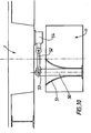
On se rapporte maintenant aux figures 8 et 9 qui représentent des amortisseurs de l'état de la technique.Referring now to Figures 8 and 9 which represent shock absorbers the state of the art.
En figures 8 et 9 est représenté un amortisseur transversal ou longitudinal
suivant l'orientation par rapport aux directions D1 et D2 de la poutre 37
déformable plastiquement.In FIGS. 8 and 9 is shown a transverse or longitudinal damper
following the orientation with respect to the directions D1 and D2 of the
La partie extrême inférieure 38 de la poutre 37 est placée dans un logement
39 de l'entretoise 11 d'un pylône 5.The
La partie extrême supérieure 40 de la poutre 37 est montée articulée autour
d'un axe 41 par rapport à une pièce 42 coulissante dans un logement 43 du
tablier 1.The
Il est entendu que l'entretoise et le tablier pourraient être des éléments quelconques d'une structure de génie civil, la structure de l'amortisseur étant identique à celle représentée.It is understood that the spacer and the apron could be elements any of a civil engineering structure, the structure of the damper being identical to that shown.
Le logement 39 comporte des moyens de calage 44 de la partie extrême
inférieure 38 de la poutre 37.The
En partie supérieure, le logement 39 comprend un gabarit de déformation 45.In the upper part, the
Dans certains modes de réalisation, ce gabarit 45 comprend au moins deux
surfaces de guidage de la déformation, sensiblement symétriques par rapport
à un plan P" médian à la poutre 37, de rayons de courbure constant sur leur
longueur ou non. In some embodiments, this
L'ouverture du gabarit 45 est alors de section rectangulaire ou carrée, le
gabarit s'évasant régulièrement vers le tablier 1.The opening of the
Dans d'autres modes de réalisation le gabarit 45 est sensiblement cylindrique
et s'évase vers le tablier 1 à la manière d'une embouchure de trompette.In other embodiments, the
L'ouverture du gabarit peut contenir un produit mou, ne résistant pas à la
compression mais protégeant la poutre 37 des agressions atmosphériques.The opening of the template may contain a soft product that is not resistant to
compression but protecting the
La poutre 37 est, dans le mode de réalisation représenté, formée par un
assemblage de plaques parallèles 37a à 37g, ces plaques étant boulonnées
et/ou soudées entre elles par tout procédé adapté connu en soi.The
Le cas échéant, ainsi qu'il est représenté, des bracons 46, 47 sont montés
articulés à leur première partie extrême 48 à l'entretoise 11 et sont solidaires,
à leur extrémité opposée à la poutre 37, sont directement, soit par
l'intermédiaire d'une pièce entourant la poutre 37.Where appropriate, as shown, the
Le terme bracon est utilisé ici dans la mesure où il désigne de manière
conventionnelle une courte pièce de soutien disposé en oblique, les pièces
46,47 disposées en oblique par rapport à la poutre 37 ayant pour fonction de
soutenir celle ci et de participer au guidage de sa déformation.The term bracon is used here in so far as it designates
conventional a short support piece arranged obliquely, the
Des plaques de glissement 49 peuvent être prévues entre les parois latérales
extrêmes de la pièce 42 et le logement 43 du tablier 1.
Ces plaques 49 peuvent être en deux parties, l'une en polytétrafluoroéthylène
PTFE solidaire du coulisseau 42, l'autre en acier inox solidaire du logement
43. These
D'autres matériaux ayant éventuellement subi un traitement de surface
peuvent être envisagés, ainsi qu'il est connu, pour obtenir des coefficients de
frottement faibles entre les parois du logement 43 et le coulisseau 42 portant
l'axe 41 de rotation de la poutre 37.Other materials that may have undergone a surface treatment
can be considered, as is known, to obtain coefficients of
weak friction between the walls of the
Le dispositif représenté en figures 8 et 9 peut être disposé verticalement ou dans tout autre direction.The device shown in FIGS. 8 and 9 can be arranged vertically or in any other direction.
Plusieurs dispositifs du type représenté en figures 8 et 9 peuvent être mis en place lors de la construction d'une structure de génie civil tel qu'un pont à haubans par exemple, ou lors du confortement d'une structure ancienne.Several devices of the type shown in FIGS. 8 and 9 can be place during the construction of a civil engineering structure such as a bridge to cable-stays for example, or during the reinforcement of an old structure.
Le cas échéant, les poutres 37 de chaque amortisseur peuvent être
disposées de manière à être déformables dans des directions différentes, par
exemple longitudinale, transversale et obliques.Where appropriate, the
Dans le deuxième mode de réalisation de l'invention, représenté en figure 10, un amortisseur, longitudinal
dans l'exemple considéré, comprend une poutre 50 pouvant être analogue
aux poutres 14,37 décrites auparavant, est placée dans un gabarit de
cintrage 51 pouvant être analogue aux gabarits de cintrages 18, 31, 45
décrits précédemment.In the second embodiment of the invention, represented in FIG. 10, a longitudinal damper
in the example considered, comprises a
La poutre 50 est articulée en rotation à une bielle 52, autour d'un axe 53.The
La bielle 52 est elle-même articulée à un coupleur hydraulique ou mécanique,
du type décrit précédemment, ce coupleur 54 étant solidaire du tablier 1.The connecting
Dans le mode de réalisation des figures 8 à 10, l'amortisseur travaille comme une console, la bielle articulée de l'amortisseur longitudinal assurant la transmission des efforts entre le tablier et le pylône. In the embodiment of Figures 8 to 10, the damper works as a console, the articulated rod of the longitudinal damper ensuring the transmission of efforts between the deck and the pylon.
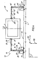
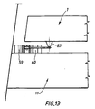
On se rapporte maintenant aux figures 11 à 13 qui illustrent un troisième mode de réalisation de l'invention.Referring now to Figures 11 to 13 which illustrate a third embodiment of the invention.
Dans ce troisième mode de réalisation, deux amortisseurs 55, 56 pourvus
chacun d'un poutre déformable plastiquement 57, 58 sont placés entre
l'entretoise 11 et le tablier 1 du pont.In this third embodiment, two
Il est entendu ici encore que le tablier 1 et l'entretoise 11 pourraient être deux
pièces quelconques d'une structure de génie civil, susceptibles de se
déplacer l'une par rapport à l'autre sous l'effet par exemple de contraintes
liées aux séismes.It is understood here again that the
Chaque poutre 57, 58 peut être déformée plastiquement sur des gabarits de
déformation 59, 60, 61, 62.Each
Plus précisément, la poutre 58 de l'amortisseur longitudinal 56 est guidée
dans sa déformation plastique éventuelle par deux surfaces courbes 63, 64 à
simple rayon de courbure sensiblement constant.More specifically, the
Ces surfaces courbes 63, 64 sont sensiblement symétriques par rapport à un
plan médian à la poutre 58, dans le mode de réalisation représenté.These
Dans d'autres modes de réalisation, non représentés, les surfaces 63, 64 ne
sont pas symétriques l'une de l'autre et/ou présentent un rayon de courbure
variable d'un bord 65 à l'autre bord 66.In other embodiments, not shown, the
Les deux extrémités de la poutre 58 sont articulées en rotation autour d'axes
67, 68 sensiblement parallèles, par rapport à deux bielles 69, 70
respectivement. The two ends of the
La bielle 69 est elle-même articulée en rotation autour d'un axe 71 par rapport
à un coupleur hydraulique ou mécanique 72, du type analogue à ceux définis
ci dessus.The connecting
De même, la bielle 70 est articulée en rotation autour d'un axe 73 par rapport
à un coupleur hydraulique ou mécanique 74 .Similarly, the connecting
Lors de la mise en place de l'amortisseur 56 pour un fonctionnement en
mode longitudinal, la poutre 58 est sensiblement placée selon la direction D2
et les bielles 70, 71 sont sensiblement parallèles à la direction D1.During the installation of the
Les axes d'articulation 67, 68, 71 et 73 sont alors sensiblement parallèles entre eux et perpendiculaires au plan T.The hinge pins 67, 68, 71 and 73 are then substantially parallel between them and perpendicular to the plane T.
La poutre 57 de l'amortisseur 55 est placée à l'origine selon la direction D1,
l'amortisseur 55 étant alors transversal.The
Cette poutre 57 est guidée dans sa déformation plastique éventuelle par deux
gabarits de guidage 59, 60 comprenant deux surfaces de guidage à simple
courbure sensiblement constante 75, 76, symétriques par rapport à un plan
médian à la poutre 57, dans le mode de réalisation représenté.This
La poutre 57 est articulée en rotation autour d'axes 77, 78 par rapport à deux
bielles 79, 80 respectivement.The
Ces bielles 79, 80 sont elles mêmes articulées en rotation autour d'axes 81,
82 définis par des pièces support d'axes 83, 84 solidaires du tablier 1.These
Lorsque l'amortisseur 55 est mis en place, la poutre 57 est sensiblement
disposée selon la direction D1 et les bielles 79, 80 sont sensiblement
parallèles à la direction D2. When the
Les axes 77, 78, 81, 82 sont alors sensiblement parallèles entre eux et
perpendiculaires au plan T.The
Dans le mode de réalisation représenté en figures 11 à 13, les gabarits 59,
60, 61 et 62 sont solidaires de l'entretoise 11 et les bielles 69, 70, 79, 80 sont
liaisonnées au tablier 1 par des articulations.In the embodiment shown in FIGS. 11 to 13, the
Dans d'autres modes de réalisation, non représentés, les gabarits sont à
l'inverse solidaires du tablier 1 et les bielles sont liaisonnées à l'entretoise 11
par des articulations.In other embodiments, not shown, the templates are
the reverse integral of the
Chaque pylône du pont peut être pourvu d'au moins un ensemble représenté en figures 11 à 13.Each pylon of the bridge may be provided with at least one assembly shown in Figures 11 to 13.
Dans un mode de réalisation, le tablier 1 est monté solidaire d'un pylône du
pont, au moins vis à vis des sollicitations longitudinales, les autres pylônes
étant pourvus de moyens amortisseurs.In one embodiment, the
En service normal du pont, les amortisseurs décrits ci dessus en référence aux trois modes de réalisation de l'invention, permettent de limiter les déplacements liés au vent et d'assurer un bon fonctionnement des joints de chaussée situés aux extrémités de l'ouvrage, tout en assurant une dissipation d'une majeure partie de l'énergie mécanique associée aux ondes sismiques sans dommages irrémédiable pour l'ouvrage et en préservant la sécurité des usagers.In normal bridge operation, the dampers described above with reference three embodiments of the invention, they make it possible to limit the wind-related movements and to ensure proper functioning of the joints pavement at the ends of the structure, while ensuring dissipation most of the mechanical energy associated with seismic waves without irreparable damage to the structure and preserving the safety of the users.
Il est rappelé que l'invention n'est nullement limitée au domaine des ponts à haubans mais concerne également le domaine des ponts suspendus ou du manière générale celui des structures dans lesquelles deux éléments de structure de génie civil sont susceptibles d'être entraínées en déplacement l'une par rapport à l'autre.It is recalled that the invention is in no way limited to the field of but also concerns the field of suspension bridges or generally speaking, structures in which two elements of civil engineering structure are likely to be driven on the move one with respect to the other.
Claims (17)
- An earthquake protection device comprising connection means (13, 13', 26, 26', 55, 56) for connecting together two movable pieces (1, 5) and limiting the relative movement of these two movable pieces (1, 5) with respect to each other, these connection means (13, 13', 26, 26', 55, 56) comprising a beam (14, 27, 27', 50, 57, 58) able to undergo plastic deformation during the relative movement of the movable pieces (1, 5) with respect to each other and means (18, 31, 51, 59, 60, 61, 62) of guiding the plastic deformation of the beam (14, 27, 27', 50, 57, 58), these guidance means (18, 31, 51, 59, 60, 61, 62) being able to be fixed to either of the movable pieces (1, 5), the device being characterised in that the connection means (13, 13', 26, 26', 55, 56) also comprise a connecting rod (15, 15', 28, 28', 52, 69, 70, 79, 80), a first end of which is articulated about a first axis (16, 16', 29, 29', 53, 67, 68, 77, 78) at an extreme end of the beam (14, 27, 27', 50, 57, 58) and a second end of which is arranged so as to enable the said connecting rod (15, 15', 28, 28', 52, 69, 70, 79, 80) to be articulated on the other movable piece (5, 1) about a second axis (20, 20', 35, 71, 73, 81, 82) substantially parallel to the first axis (16, 16', 29, 29', 53, 67, 68, 77, 78).
- A device according to Claim 1, characterised in that the beam (14, 27, 37, 50, 57, 58) and the connecting rod (15, 27, 52, 69, 70, 79, 80) are disposed perpendicular to each other when the device is put in place.
- A device according to Claim 1 or 2, characterised in that a hydraulic or mechanical coupler is connected on the one hand to the connecting-rod body and on the other hand to the movable piece with respect to which the connecting rod is articulated.
- A device according to any one of Claims 1 to 3, characterised in that the beam (14, 27, 37, 50, 57, 58) is formed from a material chosen from amongst a group comprising steels and metallic alloys, and composites with a metallic matrix.
- A device according to any one of Claims 1 to 4, characterised in that the means of guiding the plastic deformation comprise at least one mechanical piece defining a continuous or discontinuous curved surface against which the part of the connection means (14, 27, 37, 50, 57, 58) able to undergo plastic deformation folds, during the said deformation.
- A device according to any one of Claims 1 to 5, characterised in that the end part (17, 30) of the beam (14, 27) not connected to the connecting rod (15, 28) is placed in a curving jig (18, 31) fixed to one of the movable pieces (1, 11).
- A device according to any one of Claims 1 to 5, characterised in that the part of the connection means able to undergo plastic deformation comprises at least one metallic beam (50), a first end part of which extends in a housing in a first movable piece (1, 11), and a second end part of the said beam being articulated on a connecting rod (52), the intermediate portion of the said beam (50) situated between the first end part and the point of articulation on the said connecting rod being free to deform, the curved plastic deformation guide surface being situated at the end of the said housing in the said movable piece.
- A device according to any one of Claims 1 to 7, characterised in that the beam (14, 27, 37, 50, 57, 58) has a rectangular cross section overall, the curved plastic deformation guide surface of the said beam being in the form of a part of a cylinder.
- A device according to Claim 8, characterised in that the plastic deformation guide surface is formed by two curved surfaces disposed on each side of the beam and symmetrical with respect to a mid-plane of the said beam.
- A device according to any one of Claims 1 to 7, characterised in that the beam has a circular cross section overall, the curved plastic deformation guide surface being formed by a section of the surface of a torus similar to the surface of a trumpet bell, with its axis of symmetry substantially merged with that of the beam.
- A device according to any one of Claims 1 to 10, characterised in that the first and second movable pieces (1, 11) are made from concrete, steel or similar material.
- A construction such as a bridge, characterised in that it comprises at least one earthquake protection device as defined in one of Claims 1 to 11.
- A construction according to Claim 12, characterised in that it is a case of a cable-stayed bridge, comprising at least one tower (5) provided with a brace (11) forming one of the movable pieces, the bridge deck forming the other movable piece.
- A bridge according to Claim 13, its deck extending in a longitudinal direction D1, characterised in that it comprises at least one earthquake protection device forming a longitudinal damper, the said device comprising a plastically deformable metallic beam, one end part (17) of which is housed in a curving jig (18) fixed to the deck (1), the said beam extending at rest in a direction D2 substantially perpendicular to the direction D1 and being articulated on a connecting rod (15) extending in the direction D1, the said link being itself articulated on a bridge tower leg.
- A bridge according to Claim 14, characterised in that the longitudinal damper is provided with a hydraulic or mechanical coupler (22) connecting the connecting rod body (15) to the articulation axis (20) of the said connecting rod (15) of a leg of the bridge tower (5).
- A bridge according to any one of Claims 14 or 15, characterised in that it comprises at least two longitudinal dampers disposed symmetrically with respect to a mid-plane P on a leg of a tower (5).
- A bridge according to any one of Claims 14 to 16, characterised in that it comprises at least one earthquake protection device forming a transverse damper, the said device comprising a metallic beam (27), a first end part (30) of which is placed in a curving jig (31) fixed to a leg of the tower, the said beam (27) being disposed in the direction D1 and being articulated on a connecting rod (28), the said connecting rod being placed at rest in a direction D2 substantially perpendicular to D1, the said connecting rod (28) being articulated on the deck (1) with respect to an axis (35) substantially parallel to the articulation axis (29) of the beam (27) with respect to the connecting rod (28).
Priority Applications (5)
| Application Number | Priority Date | Filing Date | Title |
|---|---|---|---|
| DE69926984T DE69926984D1 (en) | 1999-02-26 | 1999-02-26 | Articulated paraseismic elastoplastic device for civil engineering and bridge with such a device |
| EP99400478A EP1031680B1 (en) | 1999-02-26 | 1999-02-26 | Articulated paraseismic elastoplastic device for civil engineering construction and bridge with such a device |
| AT99400478T ATE303489T1 (en) | 1999-02-26 | 1999-02-26 | ARTICULATE PARASEISMIC ELASTOPLASTIC DEVICE FOR CIVIL ENGINEERING AND BRIDGE COMPRISING SUCH A DEVICE |
| JP2000050463A JP2000248508A (en) | 1999-02-26 | 2000-02-22 | Earthquake resistant device and civil engineering structure having earthquake resistant device |
| HK01101499A HK1032615A1 (en) | 1999-02-26 | 2001-02-28 | Articulated paraseismic elastroplastic device for civil engineering construction and bridge with such a device |
Applications Claiming Priority (1)
| Application Number | Priority Date | Filing Date | Title |
|---|---|---|---|
| EP99400478A EP1031680B1 (en) | 1999-02-26 | 1999-02-26 | Articulated paraseismic elastoplastic device for civil engineering construction and bridge with such a device |
Publications (2)
| Publication Number | Publication Date |
|---|---|
| EP1031680A1 EP1031680A1 (en) | 2000-08-30 |
| EP1031680B1 true EP1031680B1 (en) | 2005-08-31 |
Family
ID=8241893
Family Applications (1)
| Application Number | Title | Priority Date | Filing Date |
|---|---|---|---|
| EP99400478A Expired - Lifetime EP1031680B1 (en) | 1999-02-26 | 1999-02-26 | Articulated paraseismic elastoplastic device for civil engineering construction and bridge with such a device |
Country Status (5)
| Country | Link |
|---|---|
| EP (1) | EP1031680B1 (en) |
| JP (1) | JP2000248508A (en) |
| AT (1) | ATE303489T1 (en) |
| DE (1) | DE69926984D1 (en) |
| HK (1) | HK1032615A1 (en) |
Families Citing this family (3)
| Publication number | Priority date | Publication date | Assignee | Title |
|---|---|---|---|---|
| CN102619162B (en) * | 2012-03-23 | 2014-09-17 | 中铁大桥勘测设计院集团有限公司 | Self-balancing windproof device for large-span bridge |
| CN109164041B (en) * | 2018-10-17 | 2021-06-22 | 中国航发贵阳发动机设计研究所 | Damping measurement test piece under high temperature environment |
| CN111691313B (en) * | 2020-07-09 | 2022-05-03 | 重庆交通大学 | Bridge construction is with combination support of turning |
Family Cites Families (47)
| Publication number | Priority date | Publication date | Assignee | Title |
|---|---|---|---|---|
| US3963099A (en) | 1975-05-08 | 1976-06-15 | New Zealand Inventions Development Authority | Hysteretic energy absorber |
| US4269011A (en) | 1979-06-08 | 1981-05-26 | Ikonomou Aristarchos S | Earthquake guarding system |
| HU180621B (en) | 1981-01-08 | 1983-03-28 | Budapesti Mueszaki Egyetem | Shock absorber insert set |
| CA1206981A (en) | 1983-01-17 | 1986-07-02 | Edward R. Fyfe | Deflection control device |
| US4593501A (en) | 1983-10-11 | 1986-06-10 | Isosys, Inc. | Vibration and shock isolator with adjustable stiffness |
| JPS6092571A (en) | 1983-10-27 | 1985-05-24 | 藤田 隆史 | Earthquake dampening apparatus of structure |
| HU190300B (en) | 1984-05-22 | 1986-08-28 | Budapesti Mueszaki Egyetem,Hu | Device for realizing progressive amortization serving for decreasing the seizmic stress of constructions |
| US4731966A (en) | 1985-06-19 | 1988-03-22 | Takafumi Fujita | Vibration energy absorber device |
| US4830927A (en) | 1986-02-07 | 1989-05-16 | Bridgestone Corporation | Anti-seismic bearing and assembly of anti-seismic bearings |
| US4761925A (en) | 1986-03-31 | 1988-08-09 | Bridgestone Corporation | Anti-seismic rubber bearing |
| FR2625763B2 (en) | 1986-07-21 | 1990-07-27 | Bellavista Patrice | ANISISMIC CONSTRUCTION DEVICE FOR A BUILDING |
| FR2602293B1 (en) | 1986-08-04 | 1990-08-03 | Bridgestone Corp | ANTISISMIC DEVICE |
| US4910929A (en) | 1986-08-20 | 1990-03-27 | Scholl Roger E | Added damping and stiffness elements |
| US4901486A (en) | 1987-03-06 | 1990-02-20 | Kajima Corporation | Elasto-plastic damper |
| US4991366A (en) | 1987-10-05 | 1991-02-12 | Akira Teramura | Vibration isolating device |
| US4953330A (en) | 1987-12-01 | 1990-09-04 | Mitsui Kensetsu Kabushiki Kaisha | Damping device in a structure and damping construction and damping method using those devices |
| JPH0762409B2 (en) | 1987-12-26 | 1995-07-05 | 日本鋼管株式会社 | Seismic isolation device using Coulomb friction |
| US5373670A (en) | 1988-05-06 | 1994-12-20 | Sumitomo Gomu Kogyo Kabushiki Kaisha | Shakeproof bearing |
| IT1229825B (en) | 1988-10-26 | 1991-09-13 | Fip Ind | MECHANICAL ENERGY DISSIPATOR AND LOAD LIMITER DEVICE, FOR THE CONNECTION OF STRUCTURAL ELEMENTS, PARTICULARLY DESIGNED FOR THE SEISMIC PROTECTION OF BRIDGES, VIADUCTS, BUILDINGS AND SIMILAR |
| US4910930A (en) | 1988-10-28 | 1990-03-27 | Base Isolation Consultants, Inc. | Seismic isolation structure |
| FR2643105B1 (en) | 1989-02-10 | 1995-10-13 | Bellavista Patrice | PARASISMIC INSULATOR FOR BUILDING CONSTRUCTION |
| JP2790185B2 (en) | 1989-02-15 | 1998-08-27 | 辰治 石丸 | Seismic isolation / vibration control mechanism for a structure with a differential double lever mechanism |
| US5147018A (en) | 1989-03-02 | 1992-09-15 | Kajima Corporation | Cylinder lock device for use in structure |
| US4950628A (en) | 1989-04-19 | 1990-08-21 | Corning Incorporated | Material and process to produce low thermal expansion cordierite structures |
| JP2927301B2 (en) | 1989-08-01 | 1999-07-28 | 住友ゴム工業株式会社 | Surrounding seismic isolation bearing |
| JP2671904B2 (en) | 1989-08-04 | 1997-11-05 | 鹿島建設株式会社 | Bolted elasto-plastic dampers and building joints |
| IT1239224B (en) | 1990-02-20 | 1993-09-28 | Fip Ind | DISSIPATOR ELEMENT AND LOAD LIMITER, PARTICULARLY DESIGNED FOR ANTI-SEISMIC DEVICES AND ANTI-SEISMIC SUPPORTING EQUIPMENT FOR BRIDGES, VIADUCTS, BUILDINGS AND SIMILAR. |
| FR2660353A1 (en) | 1990-03-30 | 1991-10-04 | Technologies Speciales Ingenie | Earthquake resistance methods and shields |
| IT1241781B (en) | 1990-08-30 | 1994-02-01 | Marco Carcassi | DISSIPATIVE EQUIPMENT FOR EARTHQUAKE-PROOF STRUCTURES |
| JP2883219B2 (en) | 1990-10-17 | 1999-04-19 | オイレス工業株式会社 | Seismic isolation support device |
| US5103605A (en) | 1991-04-29 | 1992-04-14 | Sul Tae H | Earthquake resistant building support system |
| JPH086494B2 (en) | 1991-06-07 | 1996-01-24 | 鹿島建設株式会社 | Vibration control device for structures |
| JP2940223B2 (en) * | 1991-06-14 | 1999-08-25 | 鹿島建設株式会社 | Active damping bridge |
| US5347771A (en) | 1991-06-20 | 1994-09-20 | Kajima Corporation | High damping device for seismic response controlled structure |
| JPH05141464A (en) | 1991-11-15 | 1993-06-08 | Kajima Corp | Laminated rubber support and vibration control device for structure using laminated rubber support |
| JPH05141463A (en) | 1991-11-15 | 1993-06-08 | Kajima Corp | Laminated rubber and vibration control device for structure using laminated rubber |
| JP2603391B2 (en) | 1991-12-25 | 1997-04-23 | 鹿島建設株式会社 | Variable damping device for damping structures |
| FR2694400A1 (en) | 1992-07-31 | 1994-02-04 | Inst Nat Polytech Grenoble | Electrode material for a potentiometric oxygen sensor operating at a temperature below 250degree C, and method for obtaining it. |
| FR2698400B1 (en) | 1992-10-29 | 1995-03-03 | Sncf | "Earthquake resistant device" for construction works, in particular for bridges and offshore platforms. |
| JPH06300081A (en) * | 1993-04-09 | 1994-10-25 | Mitsubishi Heavy Ind Ltd | Vibration damping support structure |
| EP0700488A4 (en) | 1993-06-02 | 1996-05-15 | Ind Res Ltd | Motion damper for large structures |
| US5490356A (en) | 1993-11-24 | 1996-02-13 | Mm Systems Of Arizona | Seismic isolation bearing |
| IT1270025B (en) | 1994-03-08 | 1997-04-28 | Fip Ind | DISSIPATOR AND LOAD LIMITER DEVICE, PARTICULARLY DESIGNED FOR THE REALIZATION OF CIVIL OR INDUSTRIAL WORKS WITH HIGH RESISTANCE AGAINST SEISMIC EFFECTS |
| FR2723111B1 (en) * | 1994-07-29 | 1996-10-18 | Freyssinet Int Stup | IMPROVEMENTS ON STRUCTURE TRANSMISSION DEVICES FOR CIVIL ENGINEERING WORKS |
| US5842312A (en) | 1995-03-01 | 1998-12-01 | E*Sorb Systems | Hysteretic damping apparati and methods |
| FR2756581B1 (en) | 1996-11-29 | 1999-01-22 | Campenon Bernard Sge | PARASISMIC DEVICE COMPRISING MEANS FOR GUIDING THE PLASTIC DEFORMATION OF THE MEANS OF CONNECTION BETWEEN TWO MOVING PARTS |
| JP3872561B2 (en) * | 1997-05-22 | 2007-01-24 | 三菱重工業株式会社 | Damper equipment for structures |
-
1999
- 1999-02-26 EP EP99400478A patent/EP1031680B1/en not_active Expired - Lifetime
- 1999-02-26 DE DE69926984T patent/DE69926984D1/en not_active Expired - Lifetime
- 1999-02-26 AT AT99400478T patent/ATE303489T1/en not_active IP Right Cessation
-
2000
- 2000-02-22 JP JP2000050463A patent/JP2000248508A/en active Pending
-
2001
- 2001-02-28 HK HK01101499A patent/HK1032615A1/en not_active IP Right Cessation
Also Published As
| Publication number | Publication date |
|---|---|
| EP1031680A1 (en) | 2000-08-30 |
| ATE303489T1 (en) | 2005-09-15 |
| HK1032615A1 (en) | 2001-07-27 |
| JP2000248508A (en) | 2000-09-12 |
| DE69926984D1 (en) | 2005-10-06 |
Similar Documents
| Publication | Publication Date | Title |
|---|---|---|
| CA1335475C (en) | Anchoring element, especially for concrete | |
| FR2862073A1 (en) | Strut layer vibration absorbing device for construction work e.g. guyed bridge, has vibration absorber with piston skirt and piston that are provided with respective joints articulated on respective struts | |
| EP0154577B1 (en) | Prestressed tress beam with elements in buckling state | |
| FR2743829A1 (en) | AUTOMATIC RISE FOR HYDRAULIC WORK SUCH AS THRESHOLD IN RIVER, OVERFLOW ON A DAM OR ON A PROTECTION DYE | |
| EP0340051A1 (en) | Bridge floor for long span bridge | |
| EP1031680B1 (en) | Articulated paraseismic elastoplastic device for civil engineering construction and bridge with such a device | |
| CH670484A5 (en) | ||
| FR2861503A1 (en) | Tower for support of e.g. telecommunication antenna, has two sets of stays distributed around central shaft, and deployed between node of shaft and ground and on both sides of horizontal units, respectively | |
| WO2014001736A2 (en) | High-resistance construction and method for implementing same | |
| EP0034541B1 (en) | Flue or vertical pipe for gas discharge | |
| EP0465303B1 (en) | Improvements in cable-stayed bridges, especially in their cables and pillars | |
| CA1073721A (en) | Element for the construction of a control or expansion joint, and composite element thus obtained | |
| EP0554161A1 (en) | Anchorage device for a bundle of fibre filaments | |
| WO2011095729A2 (en) | Wind turbine mounted on an anchor block | |
| EP2060687B1 (en) | Device designed to guarantee insulation in the event of thermal breakdown | |
| FR2484355A1 (en) | Under-water anchor stay - comprises prestressed concrete tie beam with end hinges and adjustable length rope | |
| FR2535281A1 (en) | Underwater bracing wire with concrete tie rods, especially for oblique bracing. | |
| FR2684401A1 (en) | Method for producing a tubular construction and construction relating thereto | |
| FR2616166A1 (en) | Bridge with composite framework and method for its construction | |
| FR2765141A1 (en) | SANDWICH PANEL WITH PROFILED CORE | |
| EP3508654A1 (en) | Composite pile | |
| EP0005092A1 (en) | Construction element in the form of a slab and structure comprising such an element | |
| BE1005070A6 (en) | Steel girder resistant to buckling by lateral tipping | |
| FR2667885A1 (en) | Method for constructing a cable-stayed bridge formed by an assembly of arch stones (voussoirs) | |
| FR2756581A1 (en) | Earthquake resistant system |
Legal Events
| Date | Code | Title | Description |
|---|---|---|---|
| PUAI | Public reference made under article 153(3) epc to a published international application that has entered the european phase |
Free format text: ORIGINAL CODE: 0009012 |
|
| AK | Designated contracting states |
Kind code of ref document: A1 Designated state(s): AT CH DE ES FR GR IT LI MC PT |
|
| AX | Request for extension of the european patent |
Free format text: AL;LT;LV;MK;RO;SI |
|
| 17P | Request for examination filed |
Effective date: 20000925 |
|
| AKX | Designation fees paid |
Free format text: AT CH DE ES FR GR IT LI MC PT |
|
| RAP1 | Party data changed (applicant data changed or rights of an application transferred) |
Owner name: CAMPENON BERNARD |
|
| RAP1 | Party data changed (applicant data changed or rights of an application transferred) |
Owner name: VINCI CONSTRUCTION GRANDS PROJETS |
|
| 17Q | First examination report despatched |
Effective date: 20030414 |
|
| RAP1 | Party data changed (applicant data changed or rights of an application transferred) |
Owner name: FREYSSINET INTERNATIONAL (STUP) Owner name: VINCI CONSTRUCTION GRANDS PROJETS |
|
| GRAP | Despatch of communication of intention to grant a patent |
Free format text: ORIGINAL CODE: EPIDOSNIGR1 |
|
| GRAS | Grant fee paid |
Free format text: ORIGINAL CODE: EPIDOSNIGR3 |
|
| GRAA | (expected) grant |
Free format text: ORIGINAL CODE: 0009210 |
|
| AK | Designated contracting states |
Kind code of ref document: B1 Designated state(s): AT CH DE ES FR GR IT LI MC PT |
|
| PG25 | Lapsed in a contracting state [announced via postgrant information from national office to epo] |
Ref country code: AT Free format text: LAPSE BECAUSE OF FAILURE TO SUBMIT A TRANSLATION OF THE DESCRIPTION OR TO PAY THE FEE WITHIN THE PRESCRIBED TIME-LIMIT Effective date: 20050831 |
|
| REG | Reference to a national code |
Ref country code: CH Ref legal event code: EP |
|
| REF | Corresponds to: |
Ref document number: 69926984 Country of ref document: DE Date of ref document: 20051006 Kind code of ref document: P |
|
| PG25 | Lapsed in a contracting state [announced via postgrant information from national office to epo] |
Ref country code: DE Free format text: LAPSE BECAUSE OF FAILURE TO SUBMIT A TRANSLATION OF THE DESCRIPTION OR TO PAY THE FEE WITHIN THE PRESCRIBED TIME-LIMIT Effective date: 20051201 |
|
| PG25 | Lapsed in a contracting state [announced via postgrant information from national office to epo] |
Ref country code: ES Free format text: LAPSE BECAUSE OF FAILURE TO SUBMIT A TRANSLATION OF THE DESCRIPTION OR TO PAY THE FEE WITHIN THE PRESCRIBED TIME-LIMIT Effective date: 20051212 |
|
| REG | Reference to a national code |
Ref country code: GR Ref legal event code: EP Ref document number: 20050403588 Country of ref document: GR |
|
| PG25 | Lapsed in a contracting state [announced via postgrant information from national office to epo] |
Ref country code: LI Free format text: LAPSE BECAUSE OF NON-PAYMENT OF DUE FEES Effective date: 20060228 Ref country code: CH Free format text: LAPSE BECAUSE OF NON-PAYMENT OF DUE FEES Effective date: 20060228 |
|
| PLBE | No opposition filed within time limit |
Free format text: ORIGINAL CODE: 0009261 |
|
| STAA | Information on the status of an ep patent application or granted ep patent |
Free format text: STATUS: NO OPPOSITION FILED WITHIN TIME LIMIT |
|
| REG | Reference to a national code |
Ref country code: HK Ref legal event code: WD Ref document number: 1032615 Country of ref document: HK |
|
| 26N | No opposition filed |
Effective date: 20060601 |
|
| REG | Reference to a national code |
Ref country code: HK Ref legal event code: GR Ref document number: 1032615 Country of ref document: HK |
|
| REG | Reference to a national code |
Ref country code: CH Ref legal event code: PL |
|
| PGFP | Annual fee paid to national office [announced via postgrant information from national office to epo] |
Ref country code: PT Payment date: 20100318 Year of fee payment: 12 Ref country code: MC Payment date: 20100329 Year of fee payment: 12 |
|
| PGFP | Annual fee paid to national office [announced via postgrant information from national office to epo] |
Ref country code: IT Payment date: 20100325 Year of fee payment: 12 |
|
| PGFP | Annual fee paid to national office [announced via postgrant information from national office to epo] |
Ref country code: GR Payment date: 20100115 Year of fee payment: 12 |
|
| REG | Reference to a national code |
Ref country code: PT Ref legal event code: MM4A Free format text: LAPSE DUE TO NON-PAYMENT OF FEES Effective date: 20110826 |
|
| PG25 | Lapsed in a contracting state [announced via postgrant information from national office to epo] |
Ref country code: MC Free format text: LAPSE BECAUSE OF NON-PAYMENT OF DUE FEES Effective date: 20110228 |
|
| PG25 | Lapsed in a contracting state [announced via postgrant information from national office to epo] |
Ref country code: PT Free format text: LAPSE BECAUSE OF NON-PAYMENT OF DUE FEES Effective date: 20110826 |
|
| PG25 | Lapsed in a contracting state [announced via postgrant information from national office to epo] |
Ref country code: GR Free format text: LAPSE BECAUSE OF NON-PAYMENT OF DUE FEES Effective date: 20110902 |
|
| PG25 | Lapsed in a contracting state [announced via postgrant information from national office to epo] |
Ref country code: IT Free format text: LAPSE BECAUSE OF NON-PAYMENT OF DUE FEES Effective date: 20110226 |
|
| REG | Reference to a national code |
Ref country code: FR Ref legal event code: PLFP Year of fee payment: 18 |
|
| REG | Reference to a national code |
Ref country code: FR Ref legal event code: PLFP Year of fee payment: 19 |
|
| REG | Reference to a national code |
Ref country code: FR Ref legal event code: PLFP Year of fee payment: 20 |
|
| PGFP | Annual fee paid to national office [announced via postgrant information from national office to epo] |
Ref country code: FR Payment date: 20171124 Year of fee payment: 20 |