EP1030396B1 - Solid polymer type fuel cell system - Google Patents
Solid polymer type fuel cell system Download PDFInfo
- Publication number
- EP1030396B1 EP1030396B1 EP99940675A EP99940675A EP1030396B1 EP 1030396 B1 EP1030396 B1 EP 1030396B1 EP 99940675 A EP99940675 A EP 99940675A EP 99940675 A EP99940675 A EP 99940675A EP 1030396 B1 EP1030396 B1 EP 1030396B1
- Authority
- EP
- European Patent Office
- Prior art keywords
- gas
- polymer electrolyte
- temperature
- cell
- fuel cells
- Prior art date
- Legal status (The legal status is an assumption and is not a legal conclusion. Google has not performed a legal analysis and makes no representation as to the accuracy of the status listed.)
- Expired - Lifetime
Links
- 239000000446 fuel Substances 0.000 title claims abstract description 91
- 239000007787 solid Substances 0.000 title claims abstract description 39
- 229920000642 polymer Polymers 0.000 title abstract description 5
- 239000012528 membrane Substances 0.000 claims abstract description 37
- 210000004027 cell Anatomy 0.000 claims description 224
- XLYOFNOQVPJJNP-UHFFFAOYSA-N water Substances O XLYOFNOQVPJJNP-UHFFFAOYSA-N 0.000 claims description 140
- 239000005518 polymer electrolyte Substances 0.000 claims description 107
- 238000001816 cooling Methods 0.000 claims description 16
- 239000002826 coolant Substances 0.000 claims description 9
- 210000005056 cell body Anatomy 0.000 claims description 4
- 238000001035 drying Methods 0.000 abstract description 3
- 239000011148 porous material Substances 0.000 abstract description 2
- 239000007789 gas Substances 0.000 description 231
- 238000009792 diffusion process Methods 0.000 description 17
- 230000000694 effects Effects 0.000 description 16
- 239000003054 catalyst Substances 0.000 description 15
- 230000001965 increasing effect Effects 0.000 description 13
- 239000002737 fuel gas Substances 0.000 description 11
- 230000001590 oxidative effect Effects 0.000 description 10
- 238000011144 upstream manufacturing Methods 0.000 description 10
- 239000012510 hollow fiber Substances 0.000 description 8
- OKTJSMMVPCPJKN-UHFFFAOYSA-N Carbon Chemical compound [C] OKTJSMMVPCPJKN-UHFFFAOYSA-N 0.000 description 7
- 238000007710 freezing Methods 0.000 description 7
- 230000008014 freezing Effects 0.000 description 7
- 238000006243 chemical reaction Methods 0.000 description 6
- 238000009833 condensation Methods 0.000 description 6
- 230000005494 condensation Effects 0.000 description 6
- 238000003411 electrode reaction Methods 0.000 description 6
- 238000000034 method Methods 0.000 description 6
- 239000000376 reactant Substances 0.000 description 6
- 238000003487 electrochemical reaction Methods 0.000 description 5
- 230000003628 erosive effect Effects 0.000 description 5
- 239000012466 permeate Substances 0.000 description 5
- 238000010248 power generation Methods 0.000 description 5
- 229910052799 carbon Inorganic materials 0.000 description 4
- 239000000498 cooling water Substances 0.000 description 4
- 230000002542 deteriorative effect Effects 0.000 description 4
- 238000004519 manufacturing process Methods 0.000 description 4
- 239000003566 sealing material Substances 0.000 description 4
- 238000012546 transfer Methods 0.000 description 4
- 239000011248 coating agent Substances 0.000 description 3
- 238000000576 coating method Methods 0.000 description 3
- 230000003247 decreasing effect Effects 0.000 description 3
- 239000003792 electrolyte Substances 0.000 description 3
- 238000010438 heat treatment Methods 0.000 description 3
- 230000003204 osmotic effect Effects 0.000 description 3
- UFHFLCQGNIYNRP-UHFFFAOYSA-N Hydrogen Chemical compound [H][H] UFHFLCQGNIYNRP-UHFFFAOYSA-N 0.000 description 2
- VYPSYNLAJGMNEJ-UHFFFAOYSA-N Silicium dioxide Chemical compound O=[Si]=O VYPSYNLAJGMNEJ-UHFFFAOYSA-N 0.000 description 2
- GWEVSGVZZGPLCZ-UHFFFAOYSA-N Titan oxide Chemical compound O=[Ti]=O GWEVSGVZZGPLCZ-UHFFFAOYSA-N 0.000 description 2
- 238000007599 discharging Methods 0.000 description 2
- 229910052739 hydrogen Inorganic materials 0.000 description 2
- 239000001257 hydrogen Substances 0.000 description 2
- 239000011261 inert gas Substances 0.000 description 2
- 239000003014 ion exchange membrane Substances 0.000 description 2
- 239000007788 liquid Substances 0.000 description 2
- 239000000463 material Substances 0.000 description 2
- 238000002844 melting Methods 0.000 description 2
- 230000008018 melting Effects 0.000 description 2
- 239000000203 mixture Substances 0.000 description 2
- 239000007800 oxidant agent Substances 0.000 description 2
- 230000008569 process Effects 0.000 description 2
- 230000005855 radiation Effects 0.000 description 2
- 238000002407 reforming Methods 0.000 description 2
- 229920006395 saturated elastomer Polymers 0.000 description 2
- XOLBLPGZBRYERU-UHFFFAOYSA-N tin dioxide Chemical compound O=[Sn]=O XOLBLPGZBRYERU-UHFFFAOYSA-N 0.000 description 2
- 229910052681 coesite Inorganic materials 0.000 description 1
- 239000002131 composite material Substances 0.000 description 1
- 239000004020 conductor Substances 0.000 description 1
- 229910052906 cristobalite Inorganic materials 0.000 description 1
- 230000001419 dependent effect Effects 0.000 description 1
- 230000006866 deterioration Effects 0.000 description 1
- 238000011161 development Methods 0.000 description 1
- 230000018109 developmental process Effects 0.000 description 1
- 230000002708 enhancing effect Effects 0.000 description 1
- 238000004880 explosion Methods 0.000 description 1
- 239000012530 fluid Substances 0.000 description 1
- UQSQSQZYBQSBJZ-UHFFFAOYSA-N fluorosulfonic acid Chemical compound OS(F)(=O)=O UQSQSQZYBQSBJZ-UHFFFAOYSA-N 0.000 description 1
- 230000009477 glass transition Effects 0.000 description 1
- XLYOFNOQVPJJNP-ZSJDYOACSA-N heavy water Substances [2H]O[2H] XLYOFNOQVPJJNP-ZSJDYOACSA-N 0.000 description 1
- 238000007731 hot pressing Methods 0.000 description 1
- GPRLSGONYQIRFK-UHFFFAOYSA-N hydron Chemical compound [H+] GPRLSGONYQIRFK-UHFFFAOYSA-N 0.000 description 1
- 230000002209 hydrophobic effect Effects 0.000 description 1
- 230000007774 longterm Effects 0.000 description 1
- 230000007246 mechanism Effects 0.000 description 1
- 239000002184 metal Substances 0.000 description 1
- 230000004048 modification Effects 0.000 description 1
- 238000012986 modification Methods 0.000 description 1
- 239000003607 modifier Substances 0.000 description 1
- 229910003465 moissanite Inorganic materials 0.000 description 1
- 239000004745 nonwoven fabric Substances 0.000 description 1
- 230000035699 permeability Effects 0.000 description 1
- 230000010287 polarization Effects 0.000 description 1
- 239000002861 polymer material Substances 0.000 description 1
- 239000000843 powder Substances 0.000 description 1
- 230000001737 promoting effect Effects 0.000 description 1
- 238000004064 recycling Methods 0.000 description 1
- HBMJWWWQQXIZIP-UHFFFAOYSA-N silicon carbide Chemical compound [Si+]#[C-] HBMJWWWQQXIZIP-UHFFFAOYSA-N 0.000 description 1
- 229910010271 silicon carbide Inorganic materials 0.000 description 1
- 239000000377 silicon dioxide Substances 0.000 description 1
- 238000000629 steam reforming Methods 0.000 description 1
- 229910052682 stishovite Inorganic materials 0.000 description 1
- 239000000126 substance Substances 0.000 description 1
- 239000004094 surface-active agent Substances 0.000 description 1
- 229910052905 tridymite Inorganic materials 0.000 description 1
- 238000013022 venting Methods 0.000 description 1
Images




Classifications
-
- H—ELECTRICITY
- H01—ELECTRIC ELEMENTS
- H01M—PROCESSES OR MEANS, e.g. BATTERIES, FOR THE DIRECT CONVERSION OF CHEMICAL ENERGY INTO ELECTRICAL ENERGY
- H01M8/00—Fuel cells; Manufacture thereof
- H01M8/02—Details
- H01M8/0202—Collectors; Separators, e.g. bipolar separators; Interconnectors
- H01M8/023—Porous and characterised by the material
-
- H—ELECTRICITY
- H01—ELECTRIC ELEMENTS
- H01M—PROCESSES OR MEANS, e.g. BATTERIES, FOR THE DIRECT CONVERSION OF CHEMICAL ENERGY INTO ELECTRICAL ENERGY
- H01M8/00—Fuel cells; Manufacture thereof
- H01M8/02—Details
- H01M8/0202—Collectors; Separators, e.g. bipolar separators; Interconnectors
- H01M8/023—Porous and characterised by the material
- H01M8/0241—Composites
- H01M8/0245—Composites in the form of layered or coated products
-
- H—ELECTRICITY
- H01—ELECTRIC ELEMENTS
- H01M—PROCESSES OR MEANS, e.g. BATTERIES, FOR THE DIRECT CONVERSION OF CHEMICAL ENERGY INTO ELECTRICAL ENERGY
- H01M8/00—Fuel cells; Manufacture thereof
- H01M8/02—Details
- H01M8/0202—Collectors; Separators, e.g. bipolar separators; Interconnectors
- H01M8/0258—Collectors; Separators, e.g. bipolar separators; Interconnectors characterised by the configuration of channels, e.g. by the flow field of the reactant or coolant
-
- H—ELECTRICITY
- H01—ELECTRIC ELEMENTS
- H01M—PROCESSES OR MEANS, e.g. BATTERIES, FOR THE DIRECT CONVERSION OF CHEMICAL ENERGY INTO ELECTRICAL ENERGY
- H01M8/00—Fuel cells; Manufacture thereof
- H01M8/02—Details
- H01M8/0202—Collectors; Separators, e.g. bipolar separators; Interconnectors
- H01M8/0267—Collectors; Separators, e.g. bipolar separators; Interconnectors having heating or cooling means, e.g. heaters or coolant flow channels
-
- H—ELECTRICITY
- H01—ELECTRIC ELEMENTS
- H01M—PROCESSES OR MEANS, e.g. BATTERIES, FOR THE DIRECT CONVERSION OF CHEMICAL ENERGY INTO ELECTRICAL ENERGY
- H01M8/00—Fuel cells; Manufacture thereof
- H01M8/04—Auxiliary arrangements, e.g. for control of pressure or for circulation of fluids
- H01M8/04007—Auxiliary arrangements, e.g. for control of pressure or for circulation of fluids related to heat exchange
- H01M8/04067—Heat exchange or temperature measuring elements, thermal insulation, e.g. heat pipes, heat pumps, fins
- H01M8/04074—Heat exchange unit structures specially adapted for fuel cell
-
- H—ELECTRICITY
- H01—ELECTRIC ELEMENTS
- H01M—PROCESSES OR MEANS, e.g. BATTERIES, FOR THE DIRECT CONVERSION OF CHEMICAL ENERGY INTO ELECTRICAL ENERGY
- H01M8/00—Fuel cells; Manufacture thereof
- H01M8/04—Auxiliary arrangements, e.g. for control of pressure or for circulation of fluids
- H01M8/04082—Arrangements for control of reactant parameters, e.g. pressure or concentration
- H01M8/04089—Arrangements for control of reactant parameters, e.g. pressure or concentration of gaseous reactants
- H01M8/04119—Arrangements for control of reactant parameters, e.g. pressure or concentration of gaseous reactants with simultaneous supply or evacuation of electrolyte; Humidifying or dehumidifying
-
- H—ELECTRICITY
- H01—ELECTRIC ELEMENTS
- H01M—PROCESSES OR MEANS, e.g. BATTERIES, FOR THE DIRECT CONVERSION OF CHEMICAL ENERGY INTO ELECTRICAL ENERGY
- H01M8/00—Fuel cells; Manufacture thereof
- H01M8/04—Auxiliary arrangements, e.g. for control of pressure or for circulation of fluids
- H01M8/04082—Arrangements for control of reactant parameters, e.g. pressure or concentration
- H01M8/04089—Arrangements for control of reactant parameters, e.g. pressure or concentration of gaseous reactants
- H01M8/04119—Arrangements for control of reactant parameters, e.g. pressure or concentration of gaseous reactants with simultaneous supply or evacuation of electrolyte; Humidifying or dehumidifying
- H01M8/04126—Humidifying
- H01M8/04149—Humidifying by diffusion, e.g. making use of membranes
-
- H—ELECTRICITY
- H01—ELECTRIC ELEMENTS
- H01M—PROCESSES OR MEANS, e.g. BATTERIES, FOR THE DIRECT CONVERSION OF CHEMICAL ENERGY INTO ELECTRICAL ENERGY
- H01M8/00—Fuel cells; Manufacture thereof
- H01M8/04—Auxiliary arrangements, e.g. for control of pressure or for circulation of fluids
- H01M8/04082—Arrangements for control of reactant parameters, e.g. pressure or concentration
- H01M8/04089—Arrangements for control of reactant parameters, e.g. pressure or concentration of gaseous reactants
- H01M8/04119—Arrangements for control of reactant parameters, e.g. pressure or concentration of gaseous reactants with simultaneous supply or evacuation of electrolyte; Humidifying or dehumidifying
- H01M8/04156—Arrangements for control of reactant parameters, e.g. pressure or concentration of gaseous reactants with simultaneous supply or evacuation of electrolyte; Humidifying or dehumidifying with product water removal
- H01M8/04171—Arrangements for control of reactant parameters, e.g. pressure or concentration of gaseous reactants with simultaneous supply or evacuation of electrolyte; Humidifying or dehumidifying with product water removal using adsorbents, wicks or hydrophilic material
-
- H—ELECTRICITY
- H01—ELECTRIC ELEMENTS
- H01M—PROCESSES OR MEANS, e.g. BATTERIES, FOR THE DIRECT CONVERSION OF CHEMICAL ENERGY INTO ELECTRICAL ENERGY
- H01M8/00—Fuel cells; Manufacture thereof
- H01M8/24—Grouping of fuel cells, e.g. stacking of fuel cells
- H01M8/241—Grouping of fuel cells, e.g. stacking of fuel cells with solid or matrix-supported electrolytes
-
- H—ELECTRICITY
- H01—ELECTRIC ELEMENTS
- H01M—PROCESSES OR MEANS, e.g. BATTERIES, FOR THE DIRECT CONVERSION OF CHEMICAL ENERGY INTO ELECTRICAL ENERGY
- H01M8/00—Fuel cells; Manufacture thereof
- H01M8/24—Grouping of fuel cells, e.g. stacking of fuel cells
- H01M8/2465—Details of groupings of fuel cells
-
- H—ELECTRICITY
- H01—ELECTRIC ELEMENTS
- H01M—PROCESSES OR MEANS, e.g. BATTERIES, FOR THE DIRECT CONVERSION OF CHEMICAL ENERGY INTO ELECTRICAL ENERGY
- H01M8/00—Fuel cells; Manufacture thereof
- H01M8/24—Grouping of fuel cells, e.g. stacking of fuel cells
- H01M8/2465—Details of groupings of fuel cells
- H01M8/2483—Details of groupings of fuel cells characterised by internal manifolds
-
- H—ELECTRICITY
- H01—ELECTRIC ELEMENTS
- H01M—PROCESSES OR MEANS, e.g. BATTERIES, FOR THE DIRECT CONVERSION OF CHEMICAL ENERGY INTO ELECTRICAL ENERGY
- H01M2300/00—Electrolytes
- H01M2300/0017—Non-aqueous electrolytes
- H01M2300/0065—Solid electrolytes
- H01M2300/0082—Organic polymers
-
- H—ELECTRICITY
- H01—ELECTRIC ELEMENTS
- H01M—PROCESSES OR MEANS, e.g. BATTERIES, FOR THE DIRECT CONVERSION OF CHEMICAL ENERGY INTO ELECTRICAL ENERGY
- H01M8/00—Fuel cells; Manufacture thereof
- H01M8/04—Auxiliary arrangements, e.g. for control of pressure or for circulation of fluids
- H01M8/04007—Auxiliary arrangements, e.g. for control of pressure or for circulation of fluids related to heat exchange
- H01M8/04014—Heat exchange using gaseous fluids; Heat exchange by combustion of reactants
-
- H—ELECTRICITY
- H01—ELECTRIC ELEMENTS
- H01M—PROCESSES OR MEANS, e.g. BATTERIES, FOR THE DIRECT CONVERSION OF CHEMICAL ENERGY INTO ELECTRICAL ENERGY
- H01M8/00—Fuel cells; Manufacture thereof
- H01M8/04—Auxiliary arrangements, e.g. for control of pressure or for circulation of fluids
- H01M8/04082—Arrangements for control of reactant parameters, e.g. pressure or concentration
- H01M8/04089—Arrangements for control of reactant parameters, e.g. pressure or concentration of gaseous reactants
- H01M8/04119—Arrangements for control of reactant parameters, e.g. pressure or concentration of gaseous reactants with simultaneous supply or evacuation of electrolyte; Humidifying or dehumidifying
- H01M8/04156—Arrangements for control of reactant parameters, e.g. pressure or concentration of gaseous reactants with simultaneous supply or evacuation of electrolyte; Humidifying or dehumidifying with product water removal
-
- Y—GENERAL TAGGING OF NEW TECHNOLOGICAL DEVELOPMENTS; GENERAL TAGGING OF CROSS-SECTIONAL TECHNOLOGIES SPANNING OVER SEVERAL SECTIONS OF THE IPC; TECHNICAL SUBJECTS COVERED BY FORMER USPC CROSS-REFERENCE ART COLLECTIONS [XRACs] AND DIGESTS
- Y02—TECHNOLOGIES OR APPLICATIONS FOR MITIGATION OR ADAPTATION AGAINST CLIMATE CHANGE
- Y02E—REDUCTION OF GREENHOUSE GAS [GHG] EMISSIONS, RELATED TO ENERGY GENERATION, TRANSMISSION OR DISTRIBUTION
- Y02E60/00—Enabling technologies; Technologies with a potential or indirect contribution to GHG emissions mitigation
- Y02E60/30—Hydrogen technology
- Y02E60/50—Fuel cells
Definitions
- This invention relates to a polymer electrolyte fuel cells system which makes use of a solid polymer as an electrolyte, and in particular to a polymer electrolyte fuel cells system having a mechanism for preventing the drying of a solid polymer electrolyte membrane.
- a fuel cells system is designed such that a fuel gas such as hydrogen or a reactive gas is rendered to electrochemically react with an oxidizing gas such as air so as to directly convert the chemical energy of the fuel to an electric energy.
- a fuel gas such as hydrogen or a reactive gas
- an oxidizing gas such as air
- This fuel cells system can be classified into various types depending on the kind of electrolyte.
- a polymer electrolyte fuel cells system which makes use of a solid polymer as an electrolyte.
- FIG. 1 shows a cross-sectional view of one example of the structure of such a polymer electrolyte fuel cells system.
- each cell 4 comprises a pair of gas-diffusing electrodes consisting of a fuel electrode (hereinafter, referred to as an anode) 1a and an oxidizing electrode (hereinafter, referred to as a cathode) 1b, and a polymer electrolyte membrane 3 having ion conductivity and gas-separating function which is interposed between the pair of gas-diffusing electrodes with a catalyst layer 2a or 2b (made of Pt for example) being interposed between the solid polymer electrolyte membrane 3 and each of the gas-diffusing electrodes.
- This cell 4 is capable of generating an electric output through a power generation by an electrochemical reaction between a fuel gas or a reactive gas and an oxidizing gas.
- This fuel cells system is constituted by a plurality of cells 4 and a gas-impermeable separator 5 provided with grooves for feeding a reactive gas to each of the electrodes of the cells 4.
- a fuel gas such as hydrogen is fed to the anode 1a, while an oxidizing gas such as air is fed to the cathode 1b so as to allow an electrochemical reaction to take place, thereby generating an electromotive force at each cell 4.
- This electromotive force of each cell 4 is as low as about 1V at most. Therefore, in order to obtain a high output, a cell stack comprising a laminate body of a plurality of cells 4 is put to practical use as a fuel cells system.
- a cooling plate 7 allowing a cooling medium to pass therethrough is disposed beside every cell laminate body 6 comprising a plurality of cells 4 which are laminated with a separator 5 being interposed between neighboring cells.
- a perfluorosulfonate film which is a fluorinated ion-exchange membrane is known.
- This solid polymer electrolyte membrane 3 contains an exchange group or hydrogen ion in its molecule and hence, functions as an ion conductive material when it is saturated with water.
- a humidifier constructed to allow water and a reactive gas to pass therethrough is disposed on both sides of a steam-permeating film such as the solid polymer electrolyte membrane 3 so as to allow the reactive gas to be wetted before it is fed to the solid polymer electrolyte membrane 3.
- the humidifier is generally formed integral with the cell stack. Further, it is also known that if a reactive gas to be fed to the anode 1a and cathode 1b is allowed to flow to face each other and at the same time, the operation temperature is controlled to not more than 60°C so as to increase the relative humidity of the reactive gas, the generation of power can be achieved without necessitating to humidify the reactive gas.
- the freezing of water passageway may be caused to generate when an external temperature is lowered, thus possibly inviting the closing of the passageway, the fracturing of the water vapor-permeating film due to the expansion in volume of ice, and the deformation of the separator 5.
- DE 42 01 632 A1 discloses a system including a fuel cell, which is characterized in that a humidifier for at least one reactant is arranged upstream of said fuel cell, wherein the humidifier contains at least two gas spaces separated from each other by a semipermeable membrane, wherein fresh reactant flowing to the fuel cell is flowing through the one of the gas spaces and the same reactant flowing out of the fuel cell is flowing through the other one of the gas spaces.
- US 3,553,026 discloses a process and a fuel cell battery comprising porous gas diffusion electrodes, which is operated to remove water of reaction by passing one or both gas mixtures containing gaseous reactants and inert gas through a first group or groups of interconnected gas spaces of electrodes of equal polarity, dehumidifying a portion or all of the effluent gas mixture containing gaseous reactant, recycling dehumified gas to the first group of gas spaces and passing a portion of the effluent gas from the first group of gas spaces to a second group of gas spaces connected in series for gas flow, and venting the inert gases from the last gas space in the series with a minimum loss of the reactant gases.
- EP 1 098 381 A1 discloses a polymer electrolyte fuel cell comprising a unit cell composed of a polymer electrolyte membrane, a cathode and an anode each having a catalyst reaction layer and disposed across said polymer electrolyte, a separator having a means for supplying a fuel gas to said anode, a separator having a means for supplying an oxidant gas to said cathode, a current collector plate, an insulating plate and an end plate laminated, wherein said fuel cell further comprises a total heat exchanger for concurrently moving heat and humidity from a discharged gas toward said fuel gas and oxidant gas being installed inside the end plates disposed on both ends of said polymer electrolyte fuel cell, or between said insulating plate and either said current collector plate or said end plate.
- an object of the present invention is to provide a polymer electrolyte fuel cells system which makes it possible to circulate water generated at an oxidizing electrode within the cell without sacrificing not only the property of cell but also the simplification and compactness of the system, thereby preventing a solid polymer electrolyte membrane from being dried, and which is excellent in performance and in compactness and capable of reliably actuating the cell system within a short time even if the ambient temperature is as low as not more than 0°C.
- the system according to the present invention comprises a main cell body, composed of a cell stack constituted by a laminated body of a plurality of cells each having a solid polymer electrolyte membrane, which is featured in that:
- the unreacted gas of lower temperature is allowed to contact face-to-face with the reacted gas of higher temperature so as to produce the condensation of water vapor contained in the reacted gas in the interior of the water retentive-porous body, thereby allowing water to permeate close to an interface contacting with the unreacted gas due to an osmotic pressure of the interior of the porous body. Accordingly, a difference in partial pressure of water vapor at the interface contacting with the unreacted gas is caused to increase, thus making it possible to greatly decrease the diffusion resistance of water vapor on the occasion when the water vapor inside the reacted gas is transferred, via the porous body, to the unreacted gas through a temperature/humidity exchange.
- the polymer electrolyte fuel cells system further comprises, means for condensing water vapor contained in the reacted gas, the means being attached to the porous body.
- the air inside a vehicle is employed as air of low temperature, the air can be utilized for heating the interior of the vehicle during a winter season, thus enhancing the efficiency of the system.
- the condensed water can be utilized for the steam modification of a fuel modifier.
- FIG. 2A shows a schematic view illustrating the principle of humidity exchange of the humidity exchange section of the polymer electrolyte fuel cells system according to this invention
- FIG. 2B is an exploded view illustrating the structures of the cell stack and humidity exchange section of the polymer electrolyte fuel cells system according to the embodiment shown in FIG. 2A
- FIGS. 3A and 3B show respectively an exploded perspective view showing the aforementioned humidity-exchanging portion in the polymer electrolyte fuel cells system.
- the same portions or members as those of FIG. 1 are represented by the same reference numerals, thereby omitting the illustration thereof. Therefore, only the portions or members which differ from those of FIG. 1 will be mainly explained hereinafter.
- the polymer electrolyte fuel cells system comprises a cell stack 9 and a temperature/humidity exchange portion 10.
- a reacted gas (gas that has been already subjected to a reaction) 100 of high temperature that has been discharged from the cell stack 9 is guided to temperature/humidity exchange portion 10 and allowed to pass through gas grooves 12 (12a and 12b) so as to be contacted through a porous body 14 with an unreacted gas 101 of low temperature.
- gas grooves 12 (12a and 12b) gas grooves 12 (12a and 12b) so as to be contacted through a porous body 14 with an unreacted gas 101 of low temperature.
- the water vapor contained in the reacted gas 100 is caused to condense in the porous body 14, the resultant condensed water being allowed to permeate to the unreacted gas 101 side.
- the temperature/ humidity exchange portion 10 may be disposed so as to be contacted with or spaced away from the cell stack 9.
- the temperature/humidity exchange portion 10 is shown as disposed away from the cell stack 9 for the convenience of explanation. As a matter of fact however, in this embodiment, the temperature/humidity exchange portion 10 is actually disposed to contact with the cell stack 9.
- the polymer electrolyte fuel cells system is designed such that the temperature/humidity exchange portion 10 is disposed to contact with the cell stack 9, thus integrating the temperature/humidity exchange portion 10 with the cell stack 9.
- the temperature/humidity exchange portion 10 is composed of a carbon separator 5 provided with gas grooves 11a or 11b for allowing the unreacted gas 101 of the anode 1a or cathode 1b to pass therethrough prior to passing through the cell stack, a carbon separator 5 provided with gas grooves 12a or 12b for allowing the reacted gas 100 of the anode 1a or cathode 1b to pass therethrough after passing through the cell stack, and a water retentive porous body 14 which is sandwiched, through the sealing material 8, between aforementioned separators 5.
- this water retentive porous body 14 is formed of a hydrophilized non-woven fabric adhered on the surface thereof with a porous membrane having pore diameter of as small as 1 ⁇ m or less. It is possible to employ other kinds of material for this porous body 14 such as a hydrophilized carbon plate, a sintered metal sheet, a fluorinated ion-exchange membrane, a composite film comprising a fluorinated porous film laminated with a fibrous polymer material, etc.
- this porous body 14 is capable of holding water condensed from water vapor included in the reacted gas, that the condensed water is allowed to pass through the porous body 14 by the effect of osmotic pressure and then enabled to evaporate due to a difference in partial pressure of water vapor at the interface facing the unreacted gas side, and that the permeability of gases other than water vapor is minimal.
- the separator 5 is provided with an anode reactive gas inlet manifold 15a, an anode reactive gas outlet manifold 15b, a cathode reactive gas inlet manifold 15c, a cathode reactive gas outlet manifold 15d, a cooling water inlet manifold 15e and a cooling water outlet manifold 15f.
- the water vapor that has been contained in the reacted gas 100 of high temperature that has passed through the cell stack 9 is caused to condense by the effect of the unreacted gas 101 of low temperature, thereby causing this condensed water to cover the region of the porous body 14 which contacts with the reacted gas 100.
- the condensed water is then caused, due to the osmotic pressure in the interior of the porous body 14, to further penetrate into the porous body 14 up to the vicinity of an interface which contacts with the unreacted gas 101. Therefore, the diffusion resistance of water vapor can be greatly minimized at the moment when the water vapor in the reacted gas 100 is subjected via the porous body to a temperature/humidity exchange with the unreacted gas 101.
- the temperature/humidity exchange portion 10 is disposed to contact with the cell stack 9, a tubing that has been conventionally employed for introducing the unreacted gas 101 into the humidifier (not shown) can be omitted.
- the system can be made compact and at the same time, the condensation of water vapor in the reacted gas due to a heat radiation at the tubing can be prevented, thus making it possible to prevent the quantity of water vapor in the reacted gas 101 which is to be fed to the temperature/humidity exchange portion 10 from being decreased.
- FIG. 4 is a graph illustrating the relationship between the area of the temperature/humidity exchange portion 10 and the relative humidity of the unreacted gas that has been humidified by the humidity exchange.
- the area of the temperature/humidity exchange portion 10 can be decreased, thus making it possible to make the system compact.
- thermo/ humidity exchange portion 10 with a gas-feeding line so as to cause the reacted gas and the unreacted gas to take a counterflow to each other with the porous body 14 being interposed therebetween, thereby making it possible to make the system further compact.
- a groove 13c for flowing a cooling medium therethrough may be provided on the back surface of the separator 5, thereby further promoting the condensation of water vapor in the reacted gas, thus making it possible to further improve the humidity exchange efficiency.
- the water vapor in the reacted gas is caused to condense inside the water retentive porous body 14.
- the humidity exchange efficiency can be improved and at the same time, the fuel cells system can be made more compact.
- cooling means it is not limited to that shown in this embodiment, but a cooling passageway for flowing a cooling medium such as an antifreezing fluid may be provided in the vicinity of the porous body 14, thus making it possible to achieve almost the same effect as mentioned above.
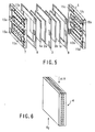
- FIG. 5 is an exploded perspective view illustrating the structure of the polymer electrolyte fuel cells system according to this embodiment
- FIG. 6 is a perspective view illustrating the structure of the cells constituting the cell stack in the polymer electrolyte fuel cells system of this embodiment.
- the arrow shown in FIG. 6 indicates the direction of the flow of reactive gas to be fed to the cell.
- the cell 4 comprises a pair of gas-diffusing electrodes consisting of an anode 1a and a cathode 1b, and a solid polymer electrolyte membrane 3 having ion conductivity and gas-separating function which is interposed between the pair of gas-diffusing electrodes with a catalyst layer 2a or 2b (made of Pt for example) being interposed between the solid polymer electrolyte membrane 3 and each of the gas-diffusing electrodes.
- This cell 4 is capable of generating an electric output through a power generation by an electrochemical reaction between a fuel gas or a reactive gas and an oxidizing gas.
- This cell 4 is sandwiched between a gas-impermeable separator 5 provided with reactive gas grooves 13a and 13b for feeding a reactive gas to each electrode, and a cooling plate 7 provided with a groove 13c for flowing a cooling medium, wherein a sealing material 8 is interposed between the cell 4 and the separator 5 as well as between the cell 4 and the cooling plate 7, thereby forming a laminate body.
- a plural number of this laminate body are further laminated one another, and the groove 13c for flowing a cooling medium is arranged in such a manner that the upstream portion of the cooling medium is positioned at the gate portion of each reactive gas.
- the cell 4 is constructed in such a manner that the flow of reactive gas to be fed to the anode 1a is directed so as to face the flow of reactive gas to be fed to the cathode 1b.
- the inlet of the cooling plate 7 is disposed at a downstream portion of reactive gas where the partial pressure of water vapor is made higher due to water generated by the electrode reaction at the cathode 1b as well as due to the consumption of reactive gas, the cooling efficiency on the downstream portion of reactive gas can be enhanced so that the downstream portion of the reactive gas becomes oversaturated with water vapor, thus causing the condensation of water to occur.
- the water thus condensed at the portion of the anode 1a or the cathode 1b which is located at the downstream portion of the reactive gas is allowed to permeate into and evaporate from the upstream portion of the reactive gas at the anode 1a or the cathode 1b (both electrodes facing each other with a solid polymer electrolyte membrane 3 being interposed therebetween) where the partial pressure of water vapor is relatively low.
- the partial pressure of water vapor at the upstream portion of the reactive gas can be increased.
- the inlet of the cooling plate 7 is disposed at a downstream portion of reactive gas, the relative humidity can be increased at the downstream portion of the reactive gas or the condensation of water can be generated. Accordingly, it is possible to increase the quantity of water vapor to be transferred from the downstream portion of reactive gas at the anode 1a or the cathode 1b where the partial pressure of water vapor is relatively high into the upstream portion of reactive gas at the anode 1a or the cathode 1b where the partial pressure of water vapor is relatively low.
- the partial pressure of water vapor in the reactive gas to be fed to the cell stack can be increased by the presence of the temperature/humidity exchange portion 10 even if a reactive gas of low relative humidity is fed to the cell stack, it is possible to obtain an excellent cell property without requiring to decrease the cell temperature even in the case of a non-humidifying operation.
- the humidifier can be omitted, thus making it possible to make the system compact and to reduce the manufacturing cost. Furthermore, since the cell system can be operated at a higher temperature than the cell temperature on the occasion of feeding a non-humidifying gas according to the prior art, it is possible to inhibit the decrease of voltage by the effect of CO.
- FIG. 7 is an exploded perspective view illustrating the structure of the polymer electrolyte fuel cells system according to this embodiment
- FIG. 8 is a perspective view illustrating the structure of the cells constituting the cell stack in the polymer electrolyte fuel cells system of this embodiment.
- the arrow shown in FIG. 8 indicates the direction of the flow of reactive gas to be fed to the cell.
- the cell 4 comprises a pair of gas-diffusing electrodes consisting of an anode 1a and a cathode 1b, and a solid polymer electrolyte membrane 3 having ion conductivity and gas-separating function which is interposed between the pair of gas-diffusing electrodes with a catalyst layer 2a or 2b (made of Pt for example) being interposed between the solid polymer electrolyte membrane 3 and each of the gas-diffusing electrodes.
- This cell 4 is capable of generating an electric output through a power generation by an electrochemical reaction between a fuel gas or a reactive gas and an oxidizing gas.
- This cell 4 is sandwiched between a gas-impermeable separator 5 provided with reactive gas grooves 13a and 13b for feeding a reactive gas to each electrode, and a cooling plate 7 provided with a groove 13c for flowing a cooling medium, wherein a sealing material 8 is interposed between the cell 4 and the separator 5 as well as between the cell 4 and the cooling plate 7, thereby forming a laminate body.
- a plural number of this laminate body are further laminated one another, and the groove 13c for flowing a cooling medium is constructed in such a manner that the interval between the grooves is relatively narrowed at the gate portion of each reactive gas.
- the cell 4 is constructed in such a manner that the flow of reactive gas to be fed to the anode 1a is directed so as to face the flow of reactive gas to be fed to the cathode 1b.
- FIG. 9 is a perspective view illustrating the structure of the cell stack of the polymer electrolyte fuel cells system according to this embodiment.
- the arrows in FIG. 9 show a flow of air by the effect of a cooling fan.
- FIG. 10 is a perspective view illustrating the structure of the cells constituting the cell stack in the polymer electrolyte fuel cells system of this embodiment. The arrow shown in FIG. 10 indicates the direction of the flow of reactive gas to be fed to the cell.
- radiation fins 16 and a cooling fan 17 are attached respectively to the upper surface and bottom surface of the cell stack 9 which is located at the gate portion of the reactive gas so as to forcibly cool the cell stack 9.
- the cell 4 is constructed in such a manner that the flow of reactive gas to be fed to the anode 1a is directed so as to face the flow of reactive gas to be fed to the cathode 1b.
- FIG. 11 is a cross-sectional view illustrating the structure of the cells constituting the cell stack in the polymer electrolyte fuel cells system of this embodiment.
- the arrow shown in FIG. 11 indicates the direction of the flow of reactive gas to be fed to the cell.
- the cell 4 comprises a pair of gas-diffusing electrodes consisting of an anode 1a and a cathode 1b, and a solid polymer electrolyte membrane 3 having ion conductivity and gals-separating function which is interposed between the pair of gas-diffusing electrodes with a catalyst layer 2a or 2b (made of Pt for example) being interposed between the solid polymer electrolyte membrane 3 and each of the gas-diffusing electrodes.
- a catalyst layer 2a or 2b made of Pt for example
- Both anode 1a and cathode 1b of the cell 4 are respectively provided in advance, at a portion thereof corresponding to the downstream portion of the reactive gas, with a hydrophilization portion 25 which is formed of a coating of ink comprising carbon powder (Vulcan XC-72R), a surfactant and pure water (solid matters: 67%), the coating of ink being dried at a temperature of 120°C after being coated.
- a hydrophilization portion 25 which is formed of a coating of ink comprising carbon powder (Vulcan XC-72R), a surfactant and pure water (solid matters: 67%), the coating of ink being dried at a temperature of 120°C after being coated.
- the entire portions of the anode 1a and the cathode 1b other than the hydrophilization portions 25 thereof are made hydrophobic for the purpose of preventing the gas diffusion layer from becoming poor in gas diffusion due to the condensed water.
- the condensed water can be trapped by this hydrophilization portion without being discharged. Namely, the water thus trapped at the downstream portion of reactive gas of the anode 1a or the cathode 1b is allowed to penetrate into the upstream portion of the reactive gas at the anode 1a or the cathode 1b (both electrodes facing each other with a solid polymer electrolyte membrane 3 being interposed therebetween) where the partial pressure of water vapor is relatively low, and then, allowed to evaporate therefrom. As a result, the partial pressure of water vapor at the upstream portion of the reactive gas can be increased.
- the partial pressure of water vapor in the reactive gas to be fed to the cell stack can be increased by the presence of the temperature/humidity exchange portion 10 even if a reactive gas of low relative humidity is fed to the cell stack, it is possible to obtain an excellent cell property without requiring to decrease the cell temperature even in the case of a non-humidifying operation.
- the humidifier can be omitted, thus making it possible to make the system compact and to reduce the manufacturing cost. Furthermore, since the cell system can be operated at a higher temperature than the cell temperature on the occasion of feeding a non-humidifying gas according to the prior art, it is possible to inhibit the decrease of voltage by the effect of CO.
- FIG. 12 is a cross-sectional view illustrating the structure of the cells constituting the cell stack in the polymer electrolyte fuel cells system of this embodiment.
- the arrow shown in FIG. 11 indicates the direction of the flow of reactive gas to be fed to the cell.
- the cell 4 comprises a pair of gas-diffusing electrodes consisting of an anode 1a and a cathode 1b, and a solid polymer electrolyte membrane 3 having ion conductivity and gas-separating function which is interposed between the pair of gas-diffusing electrodes with a catalyst layer 2a or 2b (made of Pt for example) being interposed between the solid polymer electrolyte membrane 3 and each of the gas-diffusing electrodes.
- a catalyst layer 2a or 2b made of Pt for example
- Both anode 1a and cathode 1b of the cell 4 are respectively provided, at a portion thereof corresponding to the downstream portion of the reactive gas, with a polymer electrolyte press-fitted portion 26 which is formed by hot-pressing the solid polymer electrolyte membrane 3 at about glass transition temperature thereof.
- the press-fitted portion of the solid polymer electrolyte membrane 3, i.e. the end portion of the gas diffusion electrode which corresponds to the downstream portion of the reactive gas is hydrophilized, the condensed water can be trapped by this hydrophilization portion without being discharged.
- the water thus trapped at the downstream portion of reactive gas of the anode 1a or the cathode 1b is allowed to penetrate into the upstream portion of the reactive gas at the anode 1a or the cathode 1b (both electrodes facing each other with a solid polymer electrolyte membrane 3 being interposed therebetween) where the partial pressure of water vapor is relatively low, and then, allowed to evaporate therefrom.
- the partial pressure of water vapor at the upstream portion of the reactive gas can be increased.
- the partial pressure of water vapor in the reactive gas to be fed to the cell stack can be increased by the presence of the temperature/humidity exchange portion 10 even if a reactive gas of low relative humidity is fed to the cell stack, it is possible to obtain an excellent cell property without requiring to decrease the cell temperature even in the case of a non-humidifying operation.
- the humidifier can be omitted, thus making it possible to make the system compact and to reduce the manufacturing cost. Furthermore, since the cell system can be operated at a higher temperature than the cell temperature on the occasion of feeding a non-humidifying gas according to the prior art, it is possible to inhibit the decrease of voltage by the effect of CO.
- FIG. 13 is a cross-sectional view illustrating the structure of the cells constituting the cell stack in the polymer electrolyte fuel cells system of this embodiment.
- the arrow shown in FIG. 11 indicates the direction of the flow of reactive gas to be fed to the cell.
- the cell 4 comprises a pair of gas-diffusing electrodes consisting of an anode 1a and a cathode 1b, and a solid polymer electrolyte membrane 3 having ion conductivity and gas-separating function which is interposed between the pair of gas-diffusing electrodes with a catalyst layer 2a or 2b (made of Pt for example) being interposed between the solid polymer electrolyte membrane 3 and each of the gas-diffusing electrodes.
- a portion of each of the anode 1a and cathode 1b of the cell 4, which corresponds to the downstream portion of the reactive gas, is not provided with the catalyst layer 2a or 2b.
- the portion corresponding to the downstream portion of the reactive gas where the catalyst layer 2a or 2b is not attached is incapable of generating a reaction heat by the electrode reaction, the temperature of this portion is lower than that of the electrode reaction portion, thereby increasing the relative humidity or the effect of condensing water at this downstream portion of the reactive gas.
- the water vapor on the reacted gas side at the downstream portion of the anode 1a or the cathode 1b is caused to condense, and the water thus condensed at the downstream portion of reactive gas of the anode 1a or the cathode 1b is allowed to penetrate into the unreacted gas side of the anode 1a or the cathode 1b (both electrodes facing each other with a solid polymer electrolyte membrane 3 being interposed therebetween).
- the water vapor is allowed to diffuse into the unreacted gas side due to a difference in partial pressure of water vapor, thus performing the humidification of the unreacted gas.
- the partial pressure of water vapor in the reactive gas to be fed to the cell stack can be increased by the presence of the temperature/humidity exchange portion 10 even if a reactive gas of low relative humidity is fed to the cell stack, it is possible to obtain an excellent cell property without requiring to decrease the cell temperature even in the case of a non-humidifying operation.
- the humidifier can be omitted, thus making it possible to make the system compact and to reduce the manufacturing cost. Furthermore, since the cell system can be operated at a higher temperature than the cell temperature on the occasion of feeding a non-humidifying gas according to the prior art, it is possible to inhibit the decrease of voltage by the effect of CO.
- FIG. 15 is a cross-sectional view illustrating the structure of the cells constituting the cell stack in the polymer electrolyte fuel cells system of this embodiment.
- the cell 4 comprises a pair of gas-diffusing electrodes consisting of an anode 1a and a cathode 1b, and a solid polymer electrolyte membrane 3 having ion conductivity and gas-separating function which is interposed between the pair of gas-diffusing electrodes with a catalyst layer 2a or 2b (made of Pt for example) being interposed between the solid polymer electrolyte membrane 3 and each of the gas-diffusing electrodes.
- the cell 4 is constructed in such a manner that the flow of reactive gas to be fed to the anode 1a is directed so as to face the flow of reactive gas to be fed to the cathode 1b.
- a portion of each of the anode 1a and cathode 1b of the cell 4, which is located in the vicinity of the gate of the reactive gas, is not provided with the catalyst layer 2a or 2b.
- the catalyst layer 2a or 2b is not provided at a portion of each of the anode 1a and cathode 1b which is located in the vicinity of the gate of the reactive gas.
- the transfer of proton that has been generated at the anode 1a to the cathode 1b can be obstructed, thus making it possible to prevent the generation of erosion.
- FIG. 17 is a schematic view of the polymer electrolyte fuel cells system according to this embodiment.
- the polymer electrolyte fuel cells system according to this embodiment is featured in that it is provided with a humidity exchange portion wherein the reacted gas that has passed through the cell stack is caused to contact, through a water retentive porous body, with air of lower temperature than that of the reacted gas, thereby causing the water vapor contained in the reacted gas to condense inside the water retentive porous body so as to perform a humidity exchange.
- this system comprises a cell stack 30 and a humidity exchange portion 3.
- the reacted gas that has been discharged from the cell is allowed to pass through a reacted gas passageway 34 of the humidity exchange portion 31 and then, allowed to contact, via a water retentive porous body 35, with the unreacted gas that has been transferred through a unreacted gas passageway 33.
- the water vapor is caused to condense in the porous body 35, the water thus condensed being allowed to permeate into the porous body 35 to reach the unreacted gas passageway 33.
- the condensed water reached the unreacted gas side is then caused to evaporate and diffuse depending on a difference in partial pressure of water vapor.
- part of the water that has failed to evaporate is pushed forward due to the flow of water to a reformer 31 disposed at the downstream side of the water flow, thereby enabling the water to be utilized in the reformer 31.
- the surface of the porous body 35 facing the unreacted gas side is turned into a wet state, thus maximizing the difference in partial pressure of water vapor.
- the unreacted gas is humidified.
- the water failed to be absorbed as steam by the unreacted gas is utilized as a water for the reforming in the reformer 31 that is disposed on a downstream side of the humidifying section.
- the water thus condensed can be utilized for the steam reforming of the reformer 31, thus dispensing with the employment of a water tank for reforming and hence, making it possible to enable the system to become more compact.
- the reacted gas is contacted through a water retentive porous body with the unreacted gas, the water contained in the reacted gas can be effectively transferred to the unreacted gas.
- the diffusion resistance of the water vapor can be minimized, thus making it possible to transfer as much quantity of water as possible toward the unreacted gas side, thus enabling to sufficiently humidify the unreacted gas.
- the power generation can be ensured without lowering the cell temperature.
- the system can be simplified and made more compact, and at the same time, since the system can be operated at a higher temperature as compared with the cell temperature to be employed where a non-humidified gas is fed to the system according to the prior art, the lowering of voltage due to the effect of CO can be inhibited, thus making it possible to obtain a polymer electrolyte fuel cells system which is excellent in performance and compact in size.
Landscapes
- Chemical & Material Sciences (AREA)
- Life Sciences & Earth Sciences (AREA)
- Engineering & Computer Science (AREA)
- Manufacturing & Machinery (AREA)
- Sustainable Development (AREA)
- Sustainable Energy (AREA)
- Chemical Kinetics & Catalysis (AREA)
- Electrochemistry (AREA)
- General Chemical & Material Sciences (AREA)
- Composite Materials (AREA)
- Fuel Cell (AREA)
Abstract
Description
- This invention relates to a polymer electrolyte fuel cells system which makes use of a solid polymer as an electrolyte, and in particular to a polymer electrolyte fuel cells system having a mechanism for preventing the drying of a solid polymer electrolyte membrane.
- A fuel cells system is designed such that a fuel gas such as hydrogen or a reactive gas is rendered to electrochemically react with an oxidizing gas such as air so as to directly convert the chemical energy of the fuel to an electric energy.
- This fuel cells system can be classified into various types depending on the kind of electrolyte. As one type of fuel cells system, there is known a polymer electrolyte fuel cells system which makes use of a solid polymer as an electrolyte.
-
FIG. 1 shows a cross-sectional view of one example of the structure of such a polymer electrolyte fuel cells system. - Referring to
FIG. 1 , eachcell 4 comprises a pair of gas-diffusing electrodes consisting of a fuel electrode (hereinafter, referred to as an anode) 1a and an oxidizing electrode (hereinafter, referred to as a cathode) 1b, and apolymer electrolyte membrane 3 having ion conductivity and gas-separating function which is interposed between the pair of gas-diffusing electrodes with acatalyst layer polymer electrolyte membrane 3 and each of the gas-diffusing electrodes. Thiscell 4 is capable of generating an electric output through a power generation by an electrochemical reaction between a fuel gas or a reactive gas and an oxidizing gas. - This fuel cells system is constituted by a plurality of
cells 4 and a gas-impermeable separator 5 provided with grooves for feeding a reactive gas to each of the electrodes of thecells 4. - According to this fuel cells system, a fuel gas such as hydrogen is fed to the
anode 1a, while an oxidizing gas such as air is fed to thecathode 1b so as to allow an electrochemical reaction to take place, thereby generating an electromotive force at eachcell 4. This electromotive force of eachcell 4 is as low as about 1V at most. Therefore, in order to obtain a high output, a cell stack comprising a laminate body of a plurality ofcells 4 is put to practical use as a fuel cells system. - Since the electrochemical reaction in this fuel cells system is exothermic reaction, heat is caused to generate. For the purpose of removing this superfluous heat, a
cooling plate 7 allowing a cooling medium to pass therethrough is disposed beside everycell laminate body 6 comprising a plurality ofcells 4 which are laminated with aseparator 5 being interposed between neighboring cells. - Further, if the fuel gas leaks outside the system, not only the utilization of fuel gas is deteriorated, but also there is a danger of explosion by the fuel gas. Therefore, a gas seal is applied, by making use of a sealing
material 8, to a space between the solidpolymer electrolyte membrane 3 and the gas-impermeable separator 5. - Additionally, at the location of the
cathode 1b, water is generated due to an electrode reaction. When this water is condensed at the electrode reaction site, the diffusion of gas is badly affected. Therefore, the water thus produced is required to be discharged together with unreacted gas outside the cell. - On the other hand, as for the material for the solid
polymer electrolyte membrane 3, a perfluorosulfonate film which is a fluorinated ion-exchange membrane is known. This solidpolymer electrolyte membrane 3 contains an exchange group or hydrogen ion in its molecule and hence, functions as an ion conductive material when it is saturated with water. - However, once this solid
polymer electrolyte membrane 3 is dried on the contrary, the ion conductivity thereof is lowered, thus prominently deteriorating the performance of cell. Therefore, there have been taken various measures to prevent the drying of the solidpolymer electrolyte membrane 3. - For example, there is known a method wherein a humidifier constructed to allow water and a reactive gas to pass therethrough is disposed on both sides of a steam-permeating film such as the solid
polymer electrolyte membrane 3 so as to allow the reactive gas to be wetted before it is fed to the solidpolymer electrolyte membrane 3. - In this case, the humidifier is generally formed integral with the cell stack. Further, it is also known that if a reactive gas to be fed to the
anode 1a andcathode 1b is allowed to flow to face each other and at the same time, the operation temperature is controlled to not more than 60°C so as to increase the relative humidity of the reactive gas, the generation of power can be achieved without necessitating to humidify the reactive gas. - On the other hand, as shown in Japanese Patent Unexamined Publication
H6-132038 - In this case, since water vapor is caused to generate on the
cathode side 1b due to an electrode reaction, the reacted gas is rendered to contain saturated or nearly saturated water vapor. - On the other hand, since the quantity of water vapor contained in the unreacted gas is relatively small, a difference in partial pressure of water vapor is caused to generate between the reacted and unreacted gases, so that this difference in partial pressure of water vapor can be utilized as a driving force for effecting the concentration diffusion of water vapor.
- Further, as shown in Japanese Patent Unexamined Publication
H8-273687 - Since the contact area between the reacted gas and the unreacted gas can be increased due to the employment of this hollow fiber, it becomes possible to provide a compact humidifier having a high humidification efficiency. Moreover, since a hollow fiber is employed, it becomes possible to incorporate the humidifier inside the gas manifold of the cell stack.
- However, these conventional polymer electrolyte fuel cells systems as mentioned above are accompanied with various problems that when the reactive gas is to be humidified by means of a humidifier or through a humidity exchange, the resultant system becomes inevitably sophisticated and difficult to make it compact, and also may raise various problems when it is used in a low temperature environment such as an air atmosphere of 0°C or less.
- In the case of the humidifier having a structure wherein water and reactive gas are allowed to flow along both sides of a water vapor-permeating film, the freezing of water passageway may be caused to generate when an external temperature is lowered, thus possibly inviting the closing of the passageway, the fracturing of the water vapor-permeating film due to the expansion in volume of ice, and the deformation of the
separator 5. - On the other hand, if a non-humidifying operation is to be performed without employing a humidifier, it may become difficult to ensure the long term stability of the solid
polymer electrolyte membrane 3 and of the cell performance. In addition to this problem, when the fuel cell is operated at a temperature of not more than 60°C which is lower than the ordinary operating temperature of 70 to 90°C by making use of a fuel gas containing CO as in the case of a reformed gas, the catalyst in theanode 1a is badly affected by this CO, thus resulting in the promotion of anodic polarization and hence, badly deteriorating the cell performance. - In the case of humidifying the reactive gas by respectively introducing reacted gas and unreacted gas into a gas chamber which is partitioned by means of a water vapor-permeating film, the transfer of water is effected only through a difference in partial pressure between these gases. Therefore, it has been impossible to obtain a sufficient degree of humidification because of a very large magnitude of diffusion resistance of water vapor such as the resistance to diffusion due to the concentration gradient of water vapor on the reacted gas side, the resistance to diffusion inside the water vapor-permeating film, and the resistance to diffusion on the unreacted gas side.
- Further, there is also a problem as the cell stack and the humidifier are separately disposed that part of water vapor in the reacted gas is caused to condense in a midway of the tubing for introducing a reacted gas discharged from the cell stack into the humidifier, thereby decreasing the partial pressure of water vapor of the reacted gas to be fed to the humidifier, thus further deteriorating the humidifying efficiency.
- When a hollow fiber is employed as a water vapor-permeating film on the other hand, since the transfer of water is effected only through a difference in partial pressure between the reacted gas and the unreacted gas, it has been impossible to obtain a sufficient degree of humidification though the contact area between the reacted gas and the unreacted gas can be increased. Further, if water vapor is condensed inside the hollow fiber to generate liquid water, the discharging of liquid water from the hollow fiber by means of a gas pressure would become difficult due to the capillary force, thus increasing the pressure loss of the gas and hence, deteriorating the efficiency of the system as a whole.
-
DE 42 01 632 A1 discloses a system including a fuel cell, which is characterized in that a humidifier for at least one reactant is arranged upstream of said fuel cell, wherein the humidifier contains at least two gas spaces separated from each other by a semipermeable membrane, wherein fresh reactant flowing to the fuel cell is flowing through the one of the gas spaces and the same reactant flowing out of the fuel cell is flowing through the other one of the gas spaces. -
US 3,553,026 discloses a process and a fuel cell battery comprising porous gas diffusion electrodes, which is operated to remove water of reaction by passing one or both gas mixtures containing gaseous reactants and inert gas through a first group or groups of interconnected gas spaces of electrodes of equal polarity, dehumidifying a portion or all of the effluent gas mixture containing gaseous reactant, recycling dehumified gas to the first group of gas spaces and passing a portion of the effluent gas from the first group of gas spaces to a second group of gas spaces connected in series for gas flow, and venting the inert gases from the last gas space in the series with a minimum loss of the reactant gases. -
EP 1 098 381 A1 - Therefore, an object of the present invention is to provide a polymer electrolyte fuel cells system which makes it possible to circulate water generated at an oxidizing electrode within the cell without sacrificing not only the property of cell but also the simplification and compactness of the system, thereby preventing a solid polymer electrolyte membrane from being dried, and which is excellent in performance and in compactness and capable of reliably actuating the cell system within a short time even if the ambient temperature is as low as not more than 0°C.
- The aforementioned object is achieved by a polymer electrolyte fuel cells system according to
claim 1. Further developments of the present invention are set out in the dependent claims. - In particular, the system according to the present invention comprises a main cell body, composed of a cell stack constituted by a laminated body of a plurality of cells each having a solid polymer electrolyte membrane, which is featured in that:
- the main cell body is provided with temperature/humidity exchange means which enables a reacted gas passed through the cell stack to be contacted, through a water retentive-porous body, with an unreacted gas prior to a passage of the unreacted gas through the cell stack; and that
- the temperature of the unreacted gas is controlled lower than the temperature of the reacted gas, so that the water vapor contained in the reacted gas is caused to condense on the reacted gas side of the porous body and that the resultant condensed water is allowed to pass from the reacted gas side to the unreacted gas side through the porous body.
- According to this invention as explained above, the unreacted gas of lower temperature is allowed to contact face-to-face with the reacted gas of higher temperature so as to produce the condensation of water vapor contained in the reacted gas in the interior of the water retentive-porous body, thereby allowing water to permeate close to an interface contacting with the unreacted gas due to an osmotic pressure of the interior of the porous body. Accordingly, a difference in partial pressure of water vapor at the interface contacting with the unreacted gas is caused to increase, thus making it possible to greatly decrease the diffusion resistance of water vapor on the occasion when the water vapor inside the reacted gas is transferred, via the porous body, to the unreacted gas through a temperature/humidity exchange.
- In a preferred embodiment of the present invention, the polymer electrolyte fuel cells system further comprises, means for condensing water vapor contained in the reacted gas, the means being attached to the porous body.
- According to this preferred embodiment, since water contained in the reacted gas can be removed, it is possible to prevent water from being kept remained in the discharge line of the reacted gas. At the same time, if the air inside a vehicle is employed as air of low temperature, the air can be utilized for heating the interior of the vehicle during a winter season, thus enhancing the efficiency of the system. Moreover, the condensed water can be utilized for the steam modification of a fuel modifier.
- Therefore, it is now possible according to the present invention to circulate water generated at an oxidizing electrode within the cell without sacrificing not only the property of cell but also the simplification and compactness of the system, thereby preventing a solid polymer electrolyte membrane from being dried even if the quantity of water vapor in the reactive gas to be fed is small in a non-humidifying operation. Additionally, it is possible to provide a polymer electrolyte fuel cells system which is excellent in performance and in compactness and capable of reliably actuating the cell system within a short time even if the ambient temperature is as low as not more than 0°C.
-
-
FIG. 1 is a cross-sectional view showing an example of a polymer electrolyte fuel cells system according to the prior art; -
FIGS. 2A and 2B show respectively a first embodiment of the polymer electrolyte fuel cells system according to this invention; whereinFIG. 2A is a schematic view thereof, andFIG. 2B is an exploded view thereof; -
FIGS. 3A and 3B show respectively an exploded perspective view showing a humidity-exchanging portion in the polymer electrolyte fuel cells system according to a first embodiment of this invention; -
FIG. 4 is a graph for illustrating the effects of the polymer electrolyte fuel cells system according to the first embodiment of this invention; -
FIG. 5 is an exploded perspective view of the polymer electrolyte fuel cells system according to a second embodiment of this invention; -
FIG. 6 is a perspective view illustrating the structure of the cells constituting the cell stack in the polymer electrolyte fuel cells system according to a second embodiment of this invention; -
FIG. 7 is an exploded perspective view of the polymer electrolyte fuel cells system according to a third embodiment of this invention; -
FIG. 8 is a perspective view illustrating the structure of the cells constituting the cell stack in the polymer electrolyte fuel cells system according to a third embodiment of this invention; -
FIG. 9 is a perspective view of the polymer electrolyte fuel cells system according to a fourth embodiment of this invention; -
FIG. 10 is a perspective view illustrating the structure of the cells constituting the cell stack in the polymer electrolyte fuel cells system according to a fourth embodiment of this invention; -
FIG. 11 is a cross-sectional view of the polymer electrolyte fuel cells system according to a fifth embodiment of this invention; -
FIG. 12 is a cross-sectional view of the polymer electrolyte fuel cells system according to a sixth embodiment of this invention; -
FIG. 13 is a cross-sectional view of the polymer electrolyte fuel cells system according to a seventh embodiment of this invention; -
FIG. 14 is a cross-sectional view of the polymer electrolyte fuel cells system according to a modified seventh embodiment of this invention; -
FIG. 15 is a cross-sectional view of the polymer electrolyte fuel cells system according to an eighth embodiment of this invention; -
FIG. 16 is a cross-sectional view of the polymer electrolyte fuel cells system according to a modified eighth embodiment of this invention; and -
FIG. 17 is a cross-sectional view of the polymer electrolyte fuel cells system according to a ninth embodiment of this invention. - Various embodiments of this invention will be explained in details with reference to the drawings as follows.
-
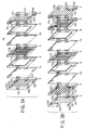
FIG. 2A shows a schematic view illustrating the principle of humidity exchange of the humidity exchange section of the polymer electrolyte fuel cells system according to this invention;FIG. 2B is an exploded view illustrating the structures of the cell stack and humidity exchange section of the polymer electrolyte fuel cells system according to the embodiment shown inFIG. 2A ; andFIGS. 3A and 3B show respectively an exploded perspective view showing the aforementioned humidity-exchanging portion in the polymer electrolyte fuel cells system. In these FIGURES. the same portions or members as those ofFIG. 1 are represented by the same reference numerals, thereby omitting the illustration thereof. Therefore, only the portions or members which differ from those ofFIG. 1 will be mainly explained hereinafter. - Referring to
FIG. 2A , the polymer electrolyte fuel cells system according to this embodiment comprises acell stack 9 and a temperature/humidity exchange portion 10. In this case, a reacted gas (gas that has been already subjected to a reaction) 100 of high temperature that has been discharged from thecell stack 9 is guided to temperature/humidity exchange portion 10 and allowed to pass through gas grooves 12 (12a and 12b) so as to be contacted through aporous body 14 with anunreacted gas 101 of low temperature. As a result, the water vapor contained in the reactedgas 100 is caused to condense in theporous body 14, the resultant condensed water being allowed to permeate to theunreacted gas 101 side. The water thus permeated is then caused to evaporate due to a difference in partial pressure, thus humidifying theunreacted gas 101. In this case, the temperature/humidity exchange portion 10 may be disposed so as to be contacted with or spaced away from thecell stack 9. InFIG. 2A , the temperature/humidity exchange portion 10 is shown as disposed away from thecell stack 9 for the convenience of explanation. As a matter of fact however, in this embodiment, the temperature/humidity exchange portion 10 is actually disposed to contact with thecell stack 9. - In
FIG. 2B , the polymer electrolyte fuel cells system is designed such that the temperature/humidity exchange portion 10 is disposed to contact with thecell stack 9, thus integrating the temperature/humidity exchange portion 10 with thecell stack 9. - As shown in
FIG. 3A , the temperature/humidity exchange portion 10 is composed of acarbon separator 5 provided withgas grooves unreacted gas 101 of theanode 1a orcathode 1b to pass therethrough prior to passing through the cell stack, acarbon separator 5 provided withgas grooves gas 100 of theanode 1a orcathode 1b to pass therethrough after passing through the cell stack, and a water retentiveporous body 14 which is sandwiched, through the sealingmaterial 8, betweenaforementioned separators 5. - In this embodiment, this water retentive
porous body 14 is formed of a hydrophilized non-woven fabric adhered on the surface thereof with a porous membrane having pore diameter of as small as 1 µm or less. It is possible to employ other kinds of material for thisporous body 14 such as a hydrophilized carbon plate, a sintered metal sheet, a fluorinated ion-exchange membrane, a composite film comprising a fluorinated porous film laminated with a fibrous polymer material, etc. - What is required for this
porous body 14 is that it is capable of holding water condensed from water vapor included in the reacted gas, that the condensed water is allowed to pass through theporous body 14 by the effect of osmotic pressure and then enabled to evaporate due to a difference in partial pressure of water vapor at the interface facing the unreacted gas side, and that the permeability of gases other than water vapor is minimal. - As shown in
FIGS. 2B and3A , theseparator 5 is provided with an anode reactivegas inlet manifold 15a, an anode reactivegas outlet manifold 15b, a cathode reactivegas inlet manifold 15c, a cathode reactivegas outlet manifold 15d, a coolingwater inlet manifold 15e and a coolingwater outlet manifold 15f. - According to the polymer electrolyte fuel cells system of this embodiment which is constructed as explained above, when a temperature/humidity exchange is allowed to take place between the reacted
gas 100 and theunreacted gas 101 at the temperature/humidity exchange portion 10, the water vapor that has been contained in the reactedgas 100 of high temperature that has passed through thecell stack 9 is caused to condense by the effect of theunreacted gas 101 of low temperature, thereby causing this condensed water to cover the region of theporous body 14 which contacts with the reactedgas 100. The condensed water is then caused, due to the osmotic pressure in the interior of theporous body 14, to further penetrate into theporous body 14 up to the vicinity of an interface which contacts with theunreacted gas 101. Therefore, the diffusion resistance of water vapor can be greatly minimized at the moment when the water vapor in the reactedgas 100 is subjected via the porous body to a temperature/humidity exchange with theunreacted gas 101. - Further, since the temperature/
humidity exchange portion 10 is disposed to contact with thecell stack 9, a tubing that has been conventionally employed for introducing theunreacted gas 101 into the humidifier (not shown) can be omitted. As a result, the system can be made compact and at the same time, the condensation of water vapor in the reacted gas due to a heat radiation at the tubing can be prevented, thus making it possible to prevent the quantity of water vapor in the reactedgas 101 which is to be fed to the temperature/humidity exchange portion 10 from being decreased. -
FIG. 4 is a graph illustrating the relationship between the area of the temperature/humidity exchange portion 10 and the relative humidity of the unreacted gas that has been humidified by the humidity exchange. As shown inFIG. 4 , it is possible, on account of the structure of this embodiment, to minimize the diffusion resistance of water vapor at the interface ofporous body 14 in the temperature/humidity exchange portion 10 as compared with the conventional humidifying method wherein the permeation of water vapor is effected by way of only the difference in partial pressure of water vapor between the gases, thereby making it possible to greatly increase the humidity exchange efficiency. As a result, the area of the temperature/humidity exchange portion 10 can be decreased, thus making it possible to make the system compact. - It is also possible to provide the temperature/
humidity exchange portion 10 with a gas-feeding line so as to cause the reacted gas and the unreacted gas to take a counterflow to each other with theporous body 14 being interposed therebetween, thereby making it possible to make the system further compact. - As shown in
FIG. 3B , agroove 13c for flowing a cooling medium therethrough may be provided on the back surface of theseparator 5, thereby further promoting the condensation of water vapor in the reacted gas, thus making it possible to further improve the humidity exchange efficiency. - As explained above, according to the polymer electrolyte fuel cells system of this embodiment, the water vapor in the reacted gas is caused to condense inside the water retentive
porous body 14. As a result, the humidity exchange efficiency can be improved and at the same time, the fuel cells system can be made more compact. - Additionally, since the reacted gas and the unreacted gas are caused to flow in a counter direction to each other, it is possible to make the system further compact.
- Further, since a heat exchange means is disposed close to the temperature/
humidity exchange portion 10, the quantity of condensation can be increased and hence, the humidity exchange efficiency can be further improved. - As for the cooling means, it is not limited to that shown in this embodiment, but a cooling passageway for flowing a cooling medium such as an antifreezing fluid may be provided in the vicinity of the
porous body 14, thus making it possible to achieve almost the same effect as mentioned above. - Although the conventional system where water is employed for the humidification is accompanied with a problem of the freezing of water, water is not employed for the humidification according to the polymer electrolyte fuel cells system of this embodiment, so that it is possible to obviate the problems such as the freezing of water, and the fracture and deformation of the film due to the freezing thereof. As a result, it is possible to provide a polymer electrolyte fuel cells system which is highly reliable and can be actuated within a short time, since a time for melting of ice is no more needed for starting the system.
- In the following, the second to eighth embodiments are not according to the present invention as claimed.
-
FIG. 5 is an exploded perspective view illustrating the structure of the polymer electrolyte fuel cells system according to this embodiment, andFIG. 6 is a perspective view illustrating the structure of the cells constituting the cell stack in the polymer electrolyte fuel cells system of this embodiment. The arrow shown inFIG. 6 indicates the direction of the flow of reactive gas to be fed to the cell. - Referring to
FIG. 5 , thecell 4 comprises a pair of gas-diffusing electrodes consisting of ananode 1a and acathode 1b, and a solidpolymer electrolyte membrane 3 having ion conductivity and gas-separating function which is interposed between the pair of gas-diffusing electrodes with acatalyst layer polymer electrolyte membrane 3 and each of the gas-diffusing electrodes. Thiscell 4 is capable of generating an electric output through a power generation by an electrochemical reaction between a fuel gas or a reactive gas and an oxidizing gas. - This
cell 4 is sandwiched between a gas-impermeable separator 5 provided withreactive gas grooves cooling plate 7 provided with agroove 13c for flowing a cooling medium, wherein a sealingmaterial 8 is interposed between thecell 4 and theseparator 5 as well as between thecell 4 and thecooling plate 7, thereby forming a laminate body. In this case, a plural number of this laminate body are further laminated one another, and thegroove 13c for flowing a cooling medium is arranged in such a manner that the upstream portion of the cooling medium is positioned at the gate portion of each reactive gas. - Further, as shown in
FIG. 6 , thecell 4 is constructed in such a manner that the flow of reactive gas to be fed to theanode 1a is directed so as to face the flow of reactive gas to be fed to thecathode 1b. - According to the polymer electrolyte fuel cells system of this embodiment which is constructed as explained above, since the inlet of the
cooling plate 7 is disposed at a downstream portion of reactive gas where the partial pressure of water vapor is made higher due to water generated by the electrode reaction at thecathode 1b as well as due to the consumption of reactive gas, the cooling efficiency on the downstream portion of reactive gas can be enhanced so that the downstream portion of the reactive gas becomes oversaturated with water vapor, thus causing the condensation of water to occur. The water thus condensed at the portion of theanode 1a or thecathode 1b which is located at the downstream portion of the reactive gas is allowed to permeate into and evaporate from the upstream portion of the reactive gas at theanode 1a or thecathode 1b (both electrodes facing each other with a solidpolymer electrolyte membrane 3 being interposed therebetween) where the partial pressure of water vapor is relatively low. As a result, the partial pressure of water vapor at the upstream portion of the reactive gas can be increased. - Additionally, since the inlet of the
cooling plate 7 is disposed at a downstream portion of reactive gas, the relative humidity can be increased at the downstream portion of the reactive gas or the condensation of water can be generated. Accordingly, it is possible to increase the quantity of water vapor to be transferred from the downstream portion of reactive gas at theanode 1a or thecathode 1b where the partial pressure of water vapor is relatively high into the upstream portion of reactive gas at theanode 1a or thecathode 1b where the partial pressure of water vapor is relatively low. - By the way, it has been confirmed that when a non-humidified reactive gas was supplied according to the system of this embodiment, it was possible to obtain almost the same cell performance as that of conventional cell at the operation temperature of 80°C which is higher than the conventional operation temperature by about 25°C. Moreover, since the operation temperature is higher as compared with that of the conventional cell, it was possible to prevent the decrease of voltage by the effect of CO.
- As mentioned above, according to the polymer electrolyte fuel cells system of this embodiment, since the partial pressure of water vapor in the reactive gas to be fed to the cell stack can be increased by the presence of the temperature/
humidity exchange portion 10 even if a reactive gas of low relative humidity is fed to the cell stack, it is possible to obtain an excellent cell property without requiring to decrease the cell temperature even in the case of a non-humidifying operation. - As a result, the humidifier can be omitted, thus making it possible to make the system compact and to reduce the manufacturing cost. Furthermore, since the cell system can be operated at a higher temperature than the cell temperature on the occasion of feeding a non-humidifying gas according to the prior art, it is possible to inhibit the decrease of voltage by the effect of CO.
-
FIG. 7 is an exploded perspective view illustrating the structure of the polymer electrolyte fuel cells system according to this embodiment, and,FIG. 8 is a perspective view illustrating the structure of the cells constituting the cell stack in the polymer electrolyte fuel cells system of this embodiment. The arrow shown inFIG. 8 indicates the direction of the flow of reactive gas to be fed to the cell. - Referring to
FIG. 7 , thecell 4 comprises a pair of gas-diffusing electrodes consisting of ananode 1a and acathode 1b, and a solidpolymer electrolyte membrane 3 having ion conductivity and gas-separating function which is interposed between the pair of gas-diffusing electrodes with acatalyst layer polymer electrolyte membrane 3 and each of the gas-diffusing electrodes. Thiscell 4 is capable of generating an electric output through a power generation by an electrochemical reaction between a fuel gas or a reactive gas and an oxidizing gas. - This
cell 4 is sandwiched between a gas-impermeable separator 5 provided withreactive gas grooves cooling plate 7 provided with agroove 13c for flowing a cooling medium, wherein a sealingmaterial 8 is interposed between thecell 4 and theseparator 5 as well as between thecell 4 and thecooling plate 7, thereby forming a laminate body. In this case, a plural number of this laminate body are further laminated one another, and thegroove 13c for flowing a cooling medium is constructed in such a manner that the interval between the grooves is relatively narrowed at the gate portion of each reactive gas. - Further, as shown in
FIG. 8 , thecell 4 is constructed in such a manner that the flow of reactive gas to be fed to theanode 1a is directed so as to face the flow of reactive gas to be fed to thecathode 1b. - According to the polymer electrolyte fuel cells system of this embodiment which is constructed as explained above, almost the same effects and advantages as in the case of the aforementioned second embodiment can be obtained.
-
FIG. 9 is a perspective view illustrating the structure of the cell stack of the polymer electrolyte fuel cells system according to this embodiment. The arrows inFIG. 9 show a flow of air by the effect of a cooling fan.FIG. 10 is a perspective view illustrating the structure of the cells constituting the cell stack in the polymer electrolyte fuel cells system of this embodiment. The arrow shown inFIG. 10 indicates the direction of the flow of reactive gas to be fed to the cell. - Referring to
FIG. 9 ,radiation fins 16 and a coolingfan 17 are attached respectively to the upper surface and bottom surface of thecell stack 9 which is located at the gate portion of the reactive gas so as to forcibly cool thecell stack 9. - Further, as shown in
FIG. 10 , thecell 4 is constructed in such a manner that the flow of reactive gas to be fed to theanode 1a is directed so as to face the flow of reactive gas to be fed to thecathode 1b. - According to the polymer electrolyte fuel cells system of this embodiment which is constructed as explained above, almost the same effects and advantages as in the case of the aforementioned third embodiment can be obtained.
- In particular, when a cooling water is not employed in the cooling of the cell portion, it becomes possible to realize a system where a cooling water is not employed, thus making it possible to improve the handleability of the system.
-
FIG. 11 is a cross-sectional view illustrating the structure of the cells constituting the cell stack in the polymer electrolyte fuel cells system of this embodiment. The arrow shown inFIG. 11 indicates the direction of the flow of reactive gas to be fed to the cell. - Referring to
FIG. 11 , thecell 4 comprises a pair of gas-diffusing electrodes consisting of ananode 1a and acathode 1b, and a solidpolymer electrolyte membrane 3 having ion conductivity and gals-separating function which is interposed between the pair of gas-diffusing electrodes with acatalyst layer polymer electrolyte membrane 3 and each of the gas-diffusing electrodes. Bothanode 1a andcathode 1b of thecell 4 are respectively provided in advance, at a portion thereof corresponding to the downstream portion of the reactive gas, with ahydrophilization portion 25 which is formed of a coating of ink comprising carbon powder (Vulcan XC-72R), a surfactant and pure water (solid matters: 67%), the coating of ink being dried at a temperature of 120°C after being coated. - In this case, the entire portions of the
anode 1a and thecathode 1b other than thehydrophilization portions 25 thereof are made hydrophobic for the purpose of preventing the gas diffusion layer from becoming poor in gas diffusion due to the condensed water. - According to the polymer electrolyte fuel cells system of this embodiment which is constructed as explained above, since an end portion of gas diffusion electrode which corresponds to the downstream portion of the reactive gas is hydrophilized by a coating of ink comprising carbon powder, the condensed water can be trapped by this hydrophilization portion without being discharged. Namely, the water thus trapped at the downstream portion of reactive gas of the
anode 1a or thecathode 1b is allowed to penetrate into the upstream portion of the reactive gas at theanode 1a or thecathode 1b (both electrodes facing each other with a solidpolymer electrolyte membrane 3 being interposed therebetween) where the partial pressure of water vapor is relatively low, and then, allowed to evaporate therefrom. As a result, the partial pressure of water vapor at the upstream portion of the reactive gas can be increased. - As mentioned above, according to the polymer electrolyte fuel cells system of this embodiment, since the partial pressure of water vapor in the reactive gas to be fed to the cell stack can be increased by the presence of the temperature/
humidity exchange portion 10 even if a reactive gas of low relative humidity is fed to the cell stack, it is possible to obtain an excellent cell property without requiring to decrease the cell temperature even in the case of a non-humidifying operation. - As a result, the humidifier can be omitted, thus making it possible to make the system compact and to reduce the manufacturing cost. Furthermore, since the cell system can be operated at a higher temperature than the cell temperature on the occasion of feeding a non-humidifying gas according to the prior art, it is possible to inhibit the decrease of voltage by the effect of CO.
- By the way, it is possible, in this embodiment, to employ an ink where a fine powder of SiC, SiO2, TiO2 or SnO2 is substituted for the aforementioned carbon powder, or to employ a solid polymer electrolyte to thereby achieve almost the same effects as mentioned above.
-
FIG. 12 is a cross-sectional view illustrating the structure of the cells constituting the cell stack in the polymer electrolyte fuel cells system of this embodiment. The arrow shown inFIG. 11 indicates the direction of the flow of reactive gas to be fed to the cell. - Referring to
FIG. 12 , thecell 4 comprises a pair of gas-diffusing electrodes consisting of ananode 1a and acathode 1b, and a solidpolymer electrolyte membrane 3 having ion conductivity and gas-separating function which is interposed between the pair of gas-diffusing electrodes with acatalyst layer polymer electrolyte membrane 3 and each of the gas-diffusing electrodes. Bothanode 1a andcathode 1b of thecell 4 are respectively provided, at a portion thereof corresponding to the downstream portion of the reactive gas, with a polymer electrolyte press-fittedportion 26 which is formed by hot-pressing the solidpolymer electrolyte membrane 3 at about glass transition temperature thereof. - According to the polymer electrolyte fuel cells system of this embodiment which is constructed as explained above, since the press-fitted portion of the solid
polymer electrolyte membrane 3, i.e. the end portion of the gas diffusion electrode which corresponds to the downstream portion of the reactive gas is hydrophilized, the condensed water can be trapped by this hydrophilization portion without being discharged. Namely, the water thus trapped at the downstream portion of reactive gas of theanode 1a or thecathode 1b is allowed to penetrate into the upstream portion of the reactive gas at theanode 1a or thecathode 1b (both electrodes facing each other with a solidpolymer electrolyte membrane 3 being interposed therebetween) where the partial pressure of water vapor is relatively low, and then, allowed to evaporate therefrom. As a result, the partial pressure of water vapor at the upstream portion of the reactive gas can be increased. - As mentioned above, according to the polymer electrolyte fuel cells system of this embodiment, since the partial pressure of water vapor in the reactive gas to be fed to the cell stack can be increased by the presence of the temperature/
humidity exchange portion 10 even if a reactive gas of low relative humidity is fed to the cell stack, it is possible to obtain an excellent cell property without requiring to decrease the cell temperature even in the case of a non-humidifying operation. - As a result, the humidifier can be omitted, thus making it possible to make the system compact and to reduce the manufacturing cost. Furthermore, since the cell system can be operated at a higher temperature than the cell temperature on the occasion of feeding a non-humidifying gas according to the prior art, it is possible to inhibit the decrease of voltage by the effect of CO.
-
FIG. 13 is a cross-sectional view illustrating the structure of the cells constituting the cell stack in the polymer electrolyte fuel cells system of this embodiment. The arrow shown inFIG. 11 indicates the direction of the flow of reactive gas to be fed to the cell. - Referring to
FIG. 13 , thecell 4 comprises a pair of gas-diffusing electrodes consisting of ananode 1a and acathode 1b, and a solidpolymer electrolyte membrane 3 having ion conductivity and gas-separating function which is interposed between the pair of gas-diffusing electrodes with acatalyst layer polymer electrolyte membrane 3 and each of the gas-diffusing electrodes. A portion of each of theanode 1a andcathode 1b of thecell 4, which corresponds to the downstream portion of the reactive gas, is not provided with thecatalyst layer - According to the polymer electrolyte fuel cells system of this embodiment which is constructed as explained above, since the portion corresponding to the downstream portion of the reactive gas where the
catalyst layer anode 1a or thecathode 1b is caused to condense, and the water thus condensed at the downstream portion of reactive gas of theanode 1a or thecathode 1b is allowed to penetrate into the unreacted gas side of theanode 1a or thecathode 1b (both electrodes facing each other with a solidpolymer electrolyte membrane 3 being interposed therebetween). As a result, the water vapor is allowed to diffuse into the unreacted gas side due to a difference in partial pressure of water vapor, thus performing the humidification of the unreacted gas. - Accordingly, it is possible to increase the quantity of water vapor to be transferred from the downstream portion of reactive gas at the
anode 1a or thecathode 1b where the partial pressure of water vapor is relatively high into the upstream portion of reactive gas at theanode 1a or thecathode 1b where the partial pressure of water vapor is relatively low. - By the way, it has been confirmed that when a non-humidified reactive gas was supplied according to the system of this embodiment, it was possible to obtain almost the same cell performance as that of conventional cell at the operation temperature of 85°C which is higher than the conventional operation temperature by about 30°C. Moreover, since the operation temperature is higher as compared with that of the conventional cell, it was possible to prevent the decrease of voltage by the effect of CO.
- As shown in
FIG. 14 , it is also possible to omit only thecatalyst layer 2a which is located in the vicinity of the outlet for the reactive gas of theanode 1a of thecell 4. - As mentioned above, according to the polymer electrolyte fuel cells system of this embodiment, since the partial pressure of water vapor in the reactive gas to be fed to the cell stack can be increased by the presence of the temperature/
humidity exchange portion 10 even if a reactive gas of low relative humidity is fed to the cell stack, it is possible to obtain an excellent cell property without requiring to decrease the cell temperature even in the case of a non-humidifying operation. - As a result, the humidifier can be omitted, thus making it possible to make the system compact and to reduce the manufacturing cost. Furthermore, since the cell system can be operated at a higher temperature than the cell temperature on the occasion of feeding a non-humidifying gas according to the prior art, it is possible to inhibit the decrease of voltage by the effect of CO.
-
FIG. 15 is a cross-sectional view illustrating the structure of the cells constituting the cell stack in the polymer electrolyte fuel cells system of this embodiment. - Referring to
FIG. 15 , thecell 4 comprises a pair of gas-diffusing electrodes consisting of ananode 1a and acathode 1b, and a solidpolymer electrolyte membrane 3 having ion conductivity and gas-separating function which is interposed between the pair of gas-diffusing electrodes with acatalyst layer polymer electrolyte membrane 3 and each of the gas-diffusing electrodes. Thecell 4 is constructed in such a manner that the flow of reactive gas to be fed to theanode 1a is directed so as to face the flow of reactive gas to be fed to thecathode 1b. A portion of each of theanode 1a andcathode 1b of thecell 4, which is located in the vicinity of the gate of the reactive gas, is not provided with thecatalyst layer - According to the polymer electrolyte fuel cells system of this embodiment which is constructed as explained above, if the diffusion of gas is poor at the downstream portion of the reactive gas, the supply of proton would be obstructed, thereby giving rise to the generation of erosion.
- For example, when a carbon electrode is employed, the erosion would be generated according to the following reaction.
C + 2H2O → CO2 + 4H+ + 4e-
- In this connection, according to the structure of this embodiment, the
catalyst layer anode 1a andcathode 1b which is located in the vicinity of the gate of the reactive gas. As a result, the transfer of proton that has been generated at theanode 1a to thecathode 1b can be obstructed, thus making it possible to prevent the generation of erosion. - By the way, even when the power generation using this embodiment was performed under an operating condition which may cause the deterioration of gas diffusion on the occasion of high load operation or low temperature operation, the erosion of electrodes was not recognized at all.
- As explained above, since erosion of electrodes can be prevented according to the polymer electrolyte fuel cells system of this embodiment, the reliability of the cell can be enhanced.
- As shown in
FIG. 16 , it is also possible to omit only thecatalyst layer 2b which is located in the vicinity of the outlet for the reactive gas of thecathode 1b of thecell 4. -
FIG. 17 is a schematic view of the polymer electrolyte fuel cells system according to this embodiment. - The polymer electrolyte fuel cells system according to this embodiment is featured in that it is provided with a humidity exchange portion wherein the reacted gas that has passed through the cell stack is caused to contact, through a water retentive porous body, with air of lower temperature than that of the reacted gas, thereby causing the water vapor contained in the reacted gas to condense inside the water retentive porous body so as to perform a humidity exchange.
- Specifically, as shown in
FIG. 17 , this system comprises acell stack 30 and ahumidity exchange portion 3. In this case, the reacted gas that has been discharged from the cell is allowed to pass through a reactedgas passageway 34 of thehumidity exchange portion 31 and then, allowed to contact, via a water retentiveporous body 35, with the unreacted gas that has been transferred through aunreacted gas passageway 33. As a result, the water vapor is caused to condense in theporous body 35, the water thus condensed being allowed to permeate into theporous body 35 to reach theunreacted gas passageway 33. The condensed water reached the unreacted gas side is then caused to evaporate and diffuse depending on a difference in partial pressure of water vapor. At the same time, part of the water that has failed to evaporate is pushed forward due to the flow of water to areformer 31 disposed at the downstream side of the water flow, thereby enabling the water to be utilized in thereformer 31. - Although unreacted gas is employed in this embodiment, it is also possible to employ part of the gas for the heating of a vehicle.
- According to the polymer electrolyte fuel cells system of this embodiment which is constructed as explained above, since water vapor is caused to be condensed into water in the
porous body 35 and the water thus condensed permeates through theporous body 35 to reach the unreacted gas side, the surface of theporous body 35 facing the unreacted gas side is turned into a wet state, thus maximizing the difference in partial pressure of water vapor. As a result, the unreacted gas is humidified. Further, the water failed to be absorbed as steam by the unreacted gas is utilized as a water for the reforming in thereformer 31 that is disposed on a downstream side of the humidifying section. - According to the polymer electrolyte fuel cells system of this embodiment which is constructed as explained above, since the water vapor contained in the reacted gas can be effectively transferred to the unreacted gas, a water-feeding passageway for humidification is no more required to be provided, so that the problem of freezing can be obviated even when the system is employed at a very cold temperature.
- Furthermore, since water contained in the reacted gas is removed, the freezing of discharging line of the reacted gas due to a residual water can be prevented, and at the same time, part of unreacted gas can be utilized as an internal air inside a vehicle for the purpose of heating the interior of the vehicle in the winter season, thus making it possible to improve the efficiency of the system.
- Additionally, the water thus condensed can be utilized for the steam reforming of the
reformer 31, thus dispensing with the employment of a water tank for reforming and hence, making it possible to enable the system to become more compact. - As explained above, according to the polymer electrolyte fuel cells system of this embodiment, since the reacted gas is contacted through a water retentive porous body with the unreacted gas, the water contained in the reacted gas can be effectively transferred to the unreacted gas. As a result, even if an unreacted gas of low relative humidity is fed to the cell stack, the diffusion resistance of the water vapor can be minimized, thus making it possible to transfer as much quantity of water as possible toward the unreacted gas side, thus enabling to sufficiently humidify the unreacted gas. As a result, even if the system is operated using an unreacted gas of non-humidified state, the power generation can be ensured without lowering the cell temperature.
- As explained above, since a humidifier employing water is no more required to be used, the problem of freezing can be obviated even if the ambient temperature is lowered to 0°C or less. Therefore, since a process of melting a frozen water can be dispensed with, a fuel cell can be actuated within a shorter time and in a simple procedure.
- Moreover, since the system can be simplified and made more compact, and at the same time, since the system can be operated at a higher temperature as compared with the cell temperature to be employed where a non-humidified gas is fed to the system according to the prior art, the lowering of voltage due to the effect of CO can be inhibited, thus making it possible to obtain a polymer electrolyte fuel cells system which is excellent in performance and compact in size.
Claims (5)
- A polymer electrolyte fuel cells system comprising a main cell body composed of a cell stack (9) constituted by a laminated body of a plurality of cells each having a solid polymer electrolyte membrane, which is featured in that:said main cell body is provided with temperature/humidity exchange means (10) which enables a reacted gas (100) passed through said cell stack (9) to be contacted, through a water retentive-porous body (14), with an unreacted gas (101) to be passed through said cell stack (9); and thatthe temperature of said unreacted gas (101) is controlled lower than the temperature of said reacted gas (100), so that the water vapor contained in the reacted gas (100) is caused to condense on the reacted gas (100) side of the porous body (14) and that the resultant condensed water is allowed to pass from the reacted gas (100) side to the unreacted gas (101) side through the porous body (14).
- The polymer electrolyte fuel cells system according to claim 1, wherein said temperature/humidity exchange means (10) is provided with a gas-feeding line so as to cause the reacted gas (100) and the unreacted gas (101) to take a counterflow to each other with the porous body (14) being interposed therebetween.
- The polymer electrolyte fuel cells system according to claim 1 or 2, wherein said temperature/humidity exchange means (10) is provided with cooling means (13c) for flowing a cooling medium for cooling the reacted gas (100), the cooling means (13c) being provided on the back surface of a separator (5) for defining the first gas groove (12a) in the temperature/humidity exchange means (10).
- The polymer electrolyte fuel cells system according to any of claims 1-3, wherein said temperature/humidity exchange means (10) is disposed to contact with the cell stack (9).
- The polymer electrolyte fuel cells system according to any of claims 1-4, further comprising means for condensing water vapor contained in the reacted gas (100), said means being attached to said porous body (14).
Applications Claiming Priority (3)
| Application Number | Priority Date | Filing Date | Title |
|---|---|---|---|
| JP25112498 | 1998-09-04 | ||
| JP25112498 | 1998-09-04 | ||
| PCT/JP1999/004817 WO2000014819A1 (en) | 1998-09-04 | 1999-09-06 | Solid polymer type fuel cell system |
Publications (4)
| Publication Number | Publication Date |
|---|---|
| EP1030396A1 EP1030396A1 (en) | 2000-08-23 |
| EP1030396A4 EP1030396A4 (en) | 2006-03-08 |
| EP1030396B1 true EP1030396B1 (en) | 2011-06-22 |
| EP1030396B8 EP1030396B8 (en) | 2012-03-14 |
Family
ID=17218034
Family Applications (1)
| Application Number | Title | Priority Date | Filing Date |
|---|---|---|---|
| EP99940675A Expired - Lifetime EP1030396B8 (en) | 1998-09-04 | 1999-09-06 | Solid polymer type fuel cell system |
Country Status (4)
| Country | Link |
|---|---|
| US (1) | US6613467B1 (en) |
| EP (1) | EP1030396B8 (en) |
| JP (2) | JP4074061B2 (en) |
| WO (1) | WO2000014819A1 (en) |
Families Citing this family (30)
| Publication number | Priority date | Publication date | Assignee | Title |
|---|---|---|---|---|
| IT1314256B1 (en) * | 1999-12-03 | 2002-12-06 | Nora Fuel Cells S P A De | POLYMERIC MEMBRANE FUEL CELL BATTERY. |
| EP1249051B1 (en) * | 2000-01-19 | 2004-04-07 | Manhattan Scientifics, Inc. | Fuel cell stack with cooling fins and use of expanded graphite in fuel cells |
| US6602625B1 (en) * | 2000-06-13 | 2003-08-05 | Hydrogenics Corporation | Fuel cell with dual end plate humidifiers |
| FR2816760B1 (en) * | 2000-11-14 | 2003-10-31 | Air Liquide | METHOD AND DEVICE FOR RECOVERING THE WATER PRODUCED BY A FUEL CELL |
| JP4737874B2 (en) * | 2001-07-16 | 2011-08-03 | 株式会社東芝 | Polymer electrolyte fuel cell system |
| JP3963716B2 (en) * | 2001-12-13 | 2007-08-22 | 本田技研工業株式会社 | Fuel cell stack |
| DE10304657B4 (en) | 2002-02-08 | 2015-07-02 | General Motors Llc ( N. D. Ges. D. Staates Delaware ) | A fuel cell stack and system and method of operating a fuel cell system having such a fuel cell stack |
| US6875535B2 (en) * | 2002-04-15 | 2005-04-05 | Hydrogenics Corporation | Manifold for a fuel cell system |
| JP4281382B2 (en) * | 2002-04-19 | 2009-06-17 | ソニー株式会社 | Generated water treatment system and power generation device |
| DE10217712A1 (en) * | 2002-04-20 | 2003-11-13 | Daimler Chrysler Ag | Electrode plate with humidification area |
| US7553567B2 (en) | 2002-08-30 | 2009-06-30 | Nissan Moto Co., Ltd. | Fuel cell system |
| JP3918691B2 (en) * | 2002-09-11 | 2007-05-23 | 日産自動車株式会社 | Polymer electrolyte fuel cell |
| JP4292368B2 (en) * | 2002-12-12 | 2009-07-08 | ソニー株式会社 | Fuel cell and electronic device equipped with the same |
| JP4604445B2 (en) * | 2002-12-25 | 2011-01-05 | パナソニック株式会社 | Fuel cell system |
| CN100461519C (en) * | 2003-09-15 | 2009-02-11 | 亚太燃料电池科技股份有限公司 | Reaction gas temperature and humidity adjusting device of fuel cell stack |
| KR100551031B1 (en) * | 2004-01-26 | 2006-02-13 | 삼성에스디아이 주식회사 | Stacks and Fuel Cell Devices Comprising the Same |
| JP2006269355A (en) * | 2005-03-25 | 2006-10-05 | Aisin Seiki Co Ltd | Fuel cell system |
| JP4753674B2 (en) * | 2005-09-21 | 2011-08-24 | 本田技研工業株式会社 | In-vehicle fuel cell system |
| JP2007323813A (en) * | 2006-05-30 | 2007-12-13 | Hitachi Ltd | Polymer electrolyte fuel cell system |
| JP5194394B2 (en) * | 2006-06-27 | 2013-05-08 | Nok株式会社 | Hollow fiber membrane module and fuel cell |
| JP2009283150A (en) * | 2008-05-19 | 2009-12-03 | Toshiba Corp | Fuel cell |
| US8557462B2 (en) * | 2009-01-14 | 2013-10-15 | Samsung Sdi Co., Ltd. | Fuel cell stack and fuel cell system using the same |
| US8347829B2 (en) * | 2009-06-02 | 2013-01-08 | James Harper | Electrolytic reactor and related methods for supplementing the air intake of an internal combustion engine |
| JP6135262B2 (en) * | 2013-04-05 | 2017-05-31 | トヨタ自動車株式会社 | FUEL CELL INSPECTION DEVICE AND INSPECTION DEVICE USING THE SAME |
| KR101481266B1 (en) | 2013-05-20 | 2015-01-09 | 현대자동차주식회사 | Humidifier for fuel cell |
| DE202013009357U1 (en) * | 2013-06-27 | 2015-01-16 | Dana Canada Corporation | Integrated gas management device for a fuel cell system |
| CN105723555B (en) * | 2013-07-30 | 2019-05-31 | 淡马锡理工学院 | fuel cell components |
| FR3040548B1 (en) * | 2015-08-24 | 2017-09-15 | Commissariat Energie Atomique | FUEL CELL FOR OPTIMIZING AIR HUMIDIFYING |
| JP6754221B2 (en) * | 2016-05-26 | 2020-09-09 | 本田技研工業株式会社 | Fuel cell system |
| JP6661220B2 (en) * | 2016-05-30 | 2020-03-11 | 本田技研工業株式会社 | Fuel cell system |
Family Cites Families (29)
| Publication number | Priority date | Publication date | Assignee | Title |
|---|---|---|---|---|
| DE1596311C2 (en) * | 1966-12-14 | 1971-05-27 | Varta Ag | Process for the condensation of water of reaction in the gas cycle and for the discharge of the inert gases in a fuel battery |
| JPS61185866A (en) * | 1985-02-14 | 1986-08-19 | Toshiba Corp | Fuel cell |
| JPH0640493B2 (en) * | 1985-09-02 | 1994-05-25 | 株式会社東芝 | Fuel cell |
| US4973530A (en) * | 1989-12-21 | 1990-11-27 | The United States Of America As Represented By The United States Department Of Energy | Fuel cell water transport |
| US5262249A (en) * | 1991-12-26 | 1993-11-16 | International Fuel Cells Corporation | Internally cooled proton exchange membrane fuel cell device |
| JPH05190184A (en) * | 1992-01-10 | 1993-07-30 | Honda Motor Co Ltd | Electrode-electrolyte assembly, method for producing the same, and fuel cell using the same |
| DE4201632C2 (en) * | 1992-01-23 | 1997-02-06 | Siemens Ag | Method and arrangement for moistening the reactants flowing into a fuel cell |
| US5272017A (en) * | 1992-04-03 | 1993-12-21 | General Motors Corporation | Membrane-electrode assemblies for electrochemical cells |
| JPH06124722A (en) * | 1992-10-09 | 1994-05-06 | Mitsubishi Heavy Ind Ltd | Heating and humidifying device and fuel cell |
| JP3111697B2 (en) * | 1992-10-20 | 2000-11-27 | 富士電機株式会社 | Solid polymer electrolyte fuel cell |
| US5382478A (en) * | 1992-11-03 | 1995-01-17 | Ballard Power Systems Inc. | Electrochemical fuel cell stack with humidification section located upstream from the electrochemically active section |
| JP3342079B2 (en) * | 1993-02-26 | 2002-11-05 | 三菱重工業株式会社 | Solid polymer electrolyte fuel cell |
| JPH07220742A (en) * | 1994-01-27 | 1995-08-18 | Matsushita Electric Ind Co Ltd | Solid polymer electrolyte fuel cell and method for producing electrode-ion exchange membrane assembly of the fuel cell |
| JP3555178B2 (en) * | 1994-05-24 | 2004-08-18 | トヨタ自動車株式会社 | Polymer electrolyte fuel cell |
| US5773160A (en) * | 1994-06-24 | 1998-06-30 | Ballard Power Systems Inc. | Electrochemical fuel cell stack with concurrent flow of coolant and oxidant streams and countercurrent flow of fuel and oxidant streams |
| JPH0831437A (en) * | 1994-07-15 | 1996-02-02 | Toshiba Corp | Fuel cell and its operating method |
| JPH08138705A (en) * | 1994-11-10 | 1996-05-31 | Toyota Motor Corp | Fuel cell humidifier |
| NL9500253A (en) * | 1995-02-10 | 1996-09-02 | Stichting Energie | Method for wetting fuel gases as well as solid polymer fuel cell. |
| JPH08273687A (en) | 1995-03-30 | 1996-10-18 | Mazda Motor Corp | Fuel gas supply gas humidifier |
| CA2222032C (en) * | 1995-05-25 | 2002-03-19 | Honda Giken Kogyo Kabushiki Kaisha | Fuel cell and method of controlling same |
| DE19602315C2 (en) * | 1996-01-23 | 2001-10-11 | Siemens Ag | Liquid-cooled fuel cell with distribution channels |
| JP3805495B2 (en) * | 1996-09-24 | 2006-08-02 | 松下電器産業株式会社 | Polymer electrolyte fuel cell |
| JPH10162842A (en) * | 1996-11-29 | 1998-06-19 | Matsushita Electric Works Ltd | Polymer electrolyte fuel cell separator and polymer electrolyte fuel cell stack using the same |
| JP3524305B2 (en) * | 1996-12-03 | 2004-05-10 | 本田技研工業株式会社 | Fuel cell |
| JPH10172587A (en) * | 1996-12-06 | 1998-06-26 | Toshiba Corp | Polymer electrolyte fuel cell |
| US5804326A (en) * | 1996-12-20 | 1998-09-08 | Ballard Power Systems Inc. | Integrated reactant and coolant fluid flow field layer for an electrochemical fuel cell |
| EP1722436B1 (en) * | 1997-12-18 | 2011-04-27 | Toyota Jidosha Kabushiki Kaisha | Polymer electrolyte fuel cell and bipolar separator for the same |
| JP3483116B2 (en) * | 1998-06-15 | 2004-01-06 | 松下電器産業株式会社 | Polymer electrolyte fuel cell |
| US6447941B1 (en) * | 1998-09-30 | 2002-09-10 | Kabushiki Kaisha Toshiba | Fuel cell |
-
1999
- 1999-09-06 WO PCT/JP1999/004817 patent/WO2000014819A1/en not_active Ceased
- 1999-09-06 JP JP2000569461A patent/JP4074061B2/en not_active Expired - Lifetime
- 1999-09-06 EP EP99940675A patent/EP1030396B8/en not_active Expired - Lifetime
-
2000
- 2000-05-03 US US09/564,475 patent/US6613467B1/en not_active Expired - Lifetime
-
2012
- 2012-08-22 JP JP2012183068A patent/JP2012253034A/en active Pending
Also Published As
| Publication number | Publication date |
|---|---|
| JP2012253034A (en) | 2012-12-20 |
| JP4074061B2 (en) | 2008-04-09 |
| WO2000014819A1 (en) | 2000-03-16 |
| US6613467B1 (en) | 2003-09-02 |
| EP1030396B8 (en) | 2012-03-14 |
| EP1030396A4 (en) | 2006-03-08 |
| EP1030396A1 (en) | 2000-08-23 |
Similar Documents
| Publication | Publication Date | Title |
|---|---|---|
| US6613467B1 (en) | Polymer electrolyte fuel cells system | |
| US6451466B1 (en) | Functional integration of multiple components for a fuel cell power plant | |
| EP1513208B1 (en) | Polymer electrolyte fuel cell system and operation method thereof | |
| US6103410A (en) | Start up of frozen fuel cell | |
| CN1209840C (en) | polymer membrane fuel cell stack | |
| US6232006B1 (en) | Dual coolant loop fuel cell power plant | |
| JPWO2000014819A1 (en) | Polymer electrolyte fuel cell system | |
| WO2001020701A1 (en) | Fine pore enthalpy exchange barrier for a fuel cell power plant | |
| JP2001185172A (en) | Fuel cell and operating method thereof | |
| WO2000079627A1 (en) | Operating system for a fuel cell power plant | |
| WO2000039874A1 (en) | Pressurized water recovery system for a fuel cell power plant | |
| JP4295847B2 (en) | Polymer electrolyte fuel cell system | |
| US6605378B2 (en) | Functional integration of multiple components for a fuel cell power plant | |
| JP3606514B2 (en) | Stacked fuel cell system | |
| JPH06338338A (en) | Humidification of high polymer ion exchange film of fuel cell | |
| AU2001268864A1 (en) | Water recovery, primarily in the cathode side, of a proton exchange membrane fuel cell | |
| WO2001097309A2 (en) | Fuel cell stack with dual end plate humidifiers | |
| JP3477926B2 (en) | Solid polymer electrolyte fuel cell | |
| KR20220130047A (en) | Humidifier for fuel cell | |
| JP2000208156A (en) | Polymer electrolyte fuel cell system | |
| JP3950562B2 (en) | Polymer electrolyte fuel cell system | |
| JP2002260708A (en) | Fuel cell laminated structure | |
| US20030148157A1 (en) | Functional integration of multiple components for a fuel cell power plant | |
| JPH0935737A (en) | Solid polymer electrolyte fuel cell | |
| JP5117173B2 (en) | Polymer electrolyte fuel cell system |
Legal Events
| Date | Code | Title | Description |
|---|---|---|---|
| PUAI | Public reference made under article 153(3) epc to a published international application that has entered the european phase |
Free format text: ORIGINAL CODE: 0009012 |
|
| 17P | Request for examination filed |
Effective date: 20000505 |
|
| AK | Designated contracting states |
Kind code of ref document: A1 Designated state(s): DE FR |
|
| A4 | Supplementary search report drawn up and despatched |
Effective date: 20060123 |
|
| RIC1 | Information provided on ipc code assigned before grant |
Ipc: H01M 4/86 20060101ALI20060117BHEP Ipc: H01M 8/24 20060101ALI20060117BHEP Ipc: H01M 8/10 20060101ALI20060117BHEP Ipc: H01M 8/04 20060101AFI20000324BHEP |
|
| 17Q | First examination report despatched |
Effective date: 20060714 |
|
| GRAP | Despatch of communication of intention to grant a patent |
Free format text: ORIGINAL CODE: EPIDOSNIGR1 |
|
| GRAS | Grant fee paid |
Free format text: ORIGINAL CODE: EPIDOSNIGR3 |
|
| GRAA | (expected) grant |
Free format text: ORIGINAL CODE: 0009210 |
|
| AK | Designated contracting states |
Kind code of ref document: B1 Designated state(s): DE FR |
|
| REG | Reference to a national code |
Ref country code: DE Ref legal event code: R096 Ref document number: 69943516 Country of ref document: DE Effective date: 20110804 |
|
| REG | Reference to a national code |
Ref country code: DE Ref legal event code: R082 Ref document number: 69943516 Country of ref document: DE Representative=s name: KRAMER - BARSKE - SCHMIDTCHEN, DE |
|
| RAP2 | Party data changed (patent owner data changed or rights of a patent transferred) |
Owner name: KABUSHIKI KAISHA TOSHIBA |
|
| REG | Reference to a national code |
Ref country code: DE Ref legal event code: R082 Ref document number: 69943516 Country of ref document: DE Representative=s name: KRAMER BARSKE SCHMIDTCHEN PATENTANWAELTE PARTG, DE Effective date: 20111108 Ref country code: DE Ref legal event code: R082 Ref document number: 69943516 Country of ref document: DE Representative=s name: KRAMER - BARSKE - SCHMIDTCHEN, DE Effective date: 20111108 Ref country code: DE Ref legal event code: R081 Ref document number: 69943516 Country of ref document: DE Owner name: KABUSHIKI KAISHA TOSHIBA, JP Free format text: FORMER OWNER: KABUSHIKI KAISHA TOSHIBA, KAWASAKI, KANAGAWA, JP Effective date: 20110615 Ref country code: DE Ref legal event code: R081 Ref document number: 69943516 Country of ref document: DE Owner name: KABUSHIKI KAISHA TOSHIBA, JP Free format text: FORMER OWNER: KABUSHIKI KAISHA TOSHIBA, KANAGAWA, JP Effective date: 20111108 |
|
| PLBE | No opposition filed within time limit |
Free format text: ORIGINAL CODE: 0009261 |
|
| STAA | Information on the status of an ep patent application or granted ep patent |
Free format text: STATUS: NO OPPOSITION FILED WITHIN TIME LIMIT |
|
| 26N | No opposition filed |
Effective date: 20120323 |
|
| REG | Reference to a national code |
Ref country code: DE Ref legal event code: R097 Ref document number: 69943516 Country of ref document: DE Effective date: 20120323 |
|
| REG | Reference to a national code |
Ref country code: FR Ref legal event code: PLFP Year of fee payment: 18 |
|
| REG | Reference to a national code |
Ref country code: FR Ref legal event code: PLFP Year of fee payment: 19 |
|
| REG | Reference to a national code |
Ref country code: FR Ref legal event code: PLFP Year of fee payment: 20 |
|
| PGFP | Annual fee paid to national office [announced via postgrant information from national office to epo] |
Ref country code: DE Payment date: 20180821 Year of fee payment: 20 Ref country code: FR Payment date: 20180813 Year of fee payment: 20 |
|
| REG | Reference to a national code |
Ref country code: DE Ref legal event code: R071 Ref document number: 69943516 Country of ref document: DE |