EP1030116B1 - Backofen - Google Patents
Backofen Download PDFInfo
- Publication number
- EP1030116B1 EP1030116B1 EP00103039A EP00103039A EP1030116B1 EP 1030116 B1 EP1030116 B1 EP 1030116B1 EP 00103039 A EP00103039 A EP 00103039A EP 00103039 A EP00103039 A EP 00103039A EP 1030116 B1 EP1030116 B1 EP 1030116B1
- Authority
- EP
- European Patent Office
- Prior art keywords
- profile
- extruded
- transverse profile
- door
- profiles
- Prior art date
- Legal status (The legal status is an assumption and is not a legal conclusion. Google has not performed a legal analysis and makes no representation as to the accuracy of the status listed.)
- Expired - Lifetime
Links
Images


Classifications
-
- F—MECHANICAL ENGINEERING; LIGHTING; HEATING; WEAPONS; BLASTING
- F24—HEATING; RANGES; VENTILATING
- F24C—DOMESTIC STOVES OR RANGES ; DETAILS OF DOMESTIC STOVES OR RANGES, OF GENERAL APPLICATION
- F24C15/00—Details
- F24C15/02—Doors specially adapted for stoves or ranges
- F24C15/04—Doors specially adapted for stoves or ranges with transparent panels
- F24C15/045—Doors specially adapted for stoves or ranges with transparent panels being dismountable, e.g. giving access for cleaning
-
- F—MECHANICAL ENGINEERING; LIGHTING; HEATING; WEAPONS; BLASTING
- F24—HEATING; RANGES; VENTILATING
- F24C—DOMESTIC STOVES OR RANGES ; DETAILS OF DOMESTIC STOVES OR RANGES, OF GENERAL APPLICATION
- F24C15/00—Details
- F24C15/02—Doors specially adapted for stoves or ranges
- F24C15/04—Doors specially adapted for stoves or ranges with transparent panels
Definitions
- the invention relates to an oven with a door, consisting of at least one inner pane, an outer pane and two arranged in side areas, parallel extruded profiles, on which the outer pane is fixed, wherein the inner pane for the purpose of cleaning of the extruded profiles is solvable.
- EP 687 867 A1 discloses appliance doors for ovens or cookers, which are composed of large-area outer and inner panes, between which two profile elements run vertically in the lateral area.
- a door handle is fixed via a screw through outer pane and spacers therethrough.
- the discs rest on elastic sealing elements.
- moisture, for example through porous sealing elements get between the panes, cleaning between the panes is possible for the user only by completely disassembling the door into their individual parts. Since the oven door consists of many individual parts, which is very cumbersome and time consuming.
- DE 195 23 772 discloses a device door, in which only the outer pane must be opened in the closed state of the door and easily removed for cleaning the inner door.
- the hinges are sized to hold the heavy, complete door open.
- an unwanted shift in the center of gravity would be the result, and the door, which would then be too light, would immediately strike unintentionally.
- a considerable manual pressure must be applied to the rest of the door.
- the outer pane must therefore be used to clean the insides of the panes be completely removed.
- the door handle is to be removed, because this is at the same time designed as an upper transversely extending receiving the outer pane. All items must be stored during cleaning. Furthermore, in such a structure when closing the outer pane disturbing noise can not be excluded, because by missing rubber buffers or similar. a dampening storage of the outer pane can not be done.
- DE 197 38 504 C1 likewise discloses a device door in which the inner pane has to be completely removed for the purpose of cleaning. This has the disadvantage that a disassembly of the door in many parts is necessary and also here enough space to store must be present.
- an oven with a door which consists of at least one inner pane, an outer pane and two in side regions arranged therebetween parallel extruded profiles, on which the outer pane is fixed.
- the inner pane is detachably arranged for the purpose of cleaning the extruded profiles.
- the inner pane has an upper transverse profile and a lower transverse profile, wherein the upper transverse profile is arranged to be pivotable and the lower transverse profile is detachably arranged on the extruded profiles and the inner pane fixed to the transverse profiles can be folded down.
- the invention thus presents the problem of creating a further oven with a device door consisting at least of inner and outer pane, in which the inner sides of the discs are easily accessible without individual parts must be completely removed and the door when removing or folding a disc can not strike unchecked.
- the achievable with the invention consist in the appliance door of a baking oven next to a foldable with simple handles inner pane in particular that this inner pane does not need to be removed for cleaning.
- a device door is a full-glass door, which consists of at least one inner, one outer pane and two arranged between these panes in the side regions, parallel extruded profiles.
- the outer pane is fixed to the extruded profiles.
- the inner pane is designed as a sealing plane to the baking muffle and is located directly on the seal, which extends around the baking muffle opening.
- the inner pane is fixed with an upper and a lower one Cross profile connected. In this case, the upper transverse profile is pivotally movable and the lower transverse profile is detachably arranged on the extruded profiles.
- connection of the transverse profile to the extruded profiles takes place on each side via an end piece, which engages in the vertically arranged extruded profiles.
- the upper transverse profile is then pivotally connected to the tail.
- the lower cross section forms the lower door closure and is detachably connected to the extruded profiles.
- a spring element is arranged which releasably engages in the lower transverse profile.
- the tail consists of a corner piece and a connecting part.
- the end piece is formed in one piece and the connecting part engages from above into the extruded profile.
- a Spring element is present, which engages in this receiving opening and is guided there displaceable.
- the end piece in the extruded profile upwards extendable or removable and to arrange a pivot point between the tail and the upper transverse profile.
- the fulcrum is realized in a particular embodiment by a arranged on the transverse profile and engaging in a receiving opening on the end pin.
- Another advantage is that the outer pane rests against the upper and lower transverse profile, wherein a complete ventilation of the door or only open at the bottom door can be realized. In the case of a fully ventilated door, the outer pane rests against the upper cross section only in some areas.
- a further advantageous embodiment provides an opening aid for releasing the inner pane from the extruded profiles in the underside of the transverse profile designed as a groove.
- the spring element arranged on the extruded profiles has an extension which is accessible below the transverse profile.
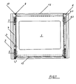
- FIG. 1 shows a solid glass appliance door (1) for an oven with an outer pane (2), an inner pane (3) and extruded profiles (4) arranged therebetween in the side areas.
- the inner pane (3) is designed as a sealing plane to the baking muffle and lies directly on a seal, not shown, which extends around the baking muffle opening.
- the handle (9) is fixed to the outer pane (2), but can also be connected in other ways with the components of the appliance door (1).
- the outer pane (2) covers the extruded profiles (4) and protrudes beyond the inner pane (3).
- hinges (5) engage in the extruded profiles (4).
- the inner pane (3) is fixed to an upper transverse profile (12) and to a lower transverse profile (13) and forms a unit therewith.
- the outer pane (2) bears against the transverse profiles (12, 13). If a device door (1) which is only open at the bottom is to be realized, the outer pane (2) bears evenly against the upper transverse profile (12) over its entire length. However, if a completely ventilated appliance door (1) is desired, the outer pane (2) rests only in partial areas on the upper transverse profile (12).
- the upper transverse profile (12) is provided on the bearing surfaces with recesses not shown here. In addition to the Contact surfaces are provided through openings, so that the air is passed through the entire interior of the door and can emerge in the upper area.
- each hollow extruded profile (4) is here covered by an end piece (6) which has a corner piece (6.1) and the connecting part (6.2).
- the connecting part (6.2) engages from above into the extruded profile (4).
- the end piece (6) not only provides a visually perfect conclusion, but the upper transverse profile (12) is also connected via a pivot point (8) with the end piece (6).
- the pivot point (8) is realized in this embodiment by a at the upper transverse profile (12) fixed pin (17) which engages in a corner piece (6.1) existing bore and is rotatably mounted there. Likewise, other trained rotary joints can be used.
- a spring element (7) is arranged, which ensures a connection to the extruded profile (4).
- the inner pane (3) is fixed to the upper transverse profile (12) and the lower transverse profile (13), for example by an adhesive bond.
- the lower transverse profile (13) forms the lower door closure and is separably connected to the extruded profiles (4).
- the inner pane (3) is detachably arranged on the extruded profile (4).
- FIG. 1 shows the side view of a full glass appliance door (1) with a on the outer pane (2) arranged handle (9).
- the handle (9) is fixed in this example on the outer pane (2) via screw (18), but may also have a different connection to the door components.
- Between the inner (3) and outer pane (2) is optionally a third to arrange, which further contributes to reducing the temperature on the outer pane (2).
- the disc (19) is for example releasably attached to the extruded profiles (4). This disc (19) can be removed for cleaning after unfolding the inner pane (3).
- hinge (5) connects the full glass appliance door (1) with a likewise not shown here oven housing.
- a spring element (11) is arranged on the extruded profile (4) for engagement in a notch (16) of the lower transverse profile (13). With engagement of this spring element (11), the discs of the door (1) are completely closed.
- An extension (11.1) of this spring element (11) serves as an aid for opening the inner pane (3). Pressing on the extension (11.1) will release it Spring element (11) from the notch (16) and the inner pane (3) can be swung.
- the transverse profile (13) is formed on its underside as a groove (15), which is also regarded as an opening aid. An engagement in this groove (15) is sufficient to thereby with a short jerk on the transverse profile (13) to release the lower connection of the inner pane (3) to the extruded profile (4).
- the end piece (6) is composed of a corner piece (6.1) and a connecting part (6.2).
- the end piece (6) is integrally formed, but it may just as well be composed of two firmly interconnected parts.
- the connecting part (6.2) engages from above into the extruded profile (4), while the corner piece (6.1) represents the optically perfect closure on the extruded profile (4).
- a spring element (7) is arranged, which engages in a recess (14) of the extruded profile (4) facing the outer pane (3).
- the recess (14) has a length (a) about which the spring element (7) in the extruded profile (4) is displaceable. This ensures that the end piece (6) with the transverse profile (12) is rotatably connected and during the unfolding of the inner pane (3) by the length (a) of the extruded profile (4) can be pulled out.
- a pivot point (8) is arranged between the upper transverse profile (12) and the end piece (6) between the upper transverse profile (12) and the end piece (6) .
- the spring element (7) moves up to the maximum distance (a) in the recess (14) of the extruded profile (4). Since the spring element (7) connected to the end piece (6) and the transverse profile (12) is rotatably mounted on the end piece (6), the inner disc (3) fixed on the transverse profile (12) also shifts upward when opened and can move upwards be folded.
- the inner pane (3) can be completely from the other door components, such as extruded profile (4) and outer pane (2) fold down and it can by simultaneous rotation in the fulcrum (8) and pulling out of the extruded profiles (4) by the length (a) to be flipped over 270 °. This means that the inner pane (3) is opened so far that it hangs completely downwards.
- the upper pivot point (8) is particularly important, because a shift in the center of gravity in the sense of stability is ensured even with an unfolded inner pane (3) and the door (1) can not strike uncontrollably. Even an inner third disc (19) can be easily removed without changing the center of gravity, because the unfolded inner disc (3) pivots in the pivot point (8) downwards and guarantees the center of gravity displacement in terms of stability.
- a release of the door hinges (5) allows a complete removal of the door (1), so that they o.ä. on a countertop. can be stored in the kitchen. Then the appliance door (1) is located so far above the floor that unfolding the inner pane (3) takes place in a position in which the user can take an ergonomically favorable attitude for cleaning.
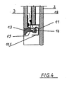
- FIG. 4 shows a detail of the lower region of FIG. 3.
- the lower cross-section (13) is firmly connected by an adhesive bond with the inner pane (3). But it is detachably arranged on the extruded profiles (4).
- the transverse profile (13) has a notch (16) for engaging a spring element (11) arranged at the lower region of the extruded profile (4).
- the notch (16) is formed either continuously over the entire length of the transverse profile (13) or at least in the areas near the spring elements (11) on the extruded profiles (4).
- the spring element (11) can be equipped with an extension (11.1).
Landscapes
- Engineering & Computer Science (AREA)
- Chemical & Material Sciences (AREA)
- Combustion & Propulsion (AREA)
- Mechanical Engineering (AREA)
- General Engineering & Computer Science (AREA)
- Securing Of Glass Panes Or The Like (AREA)
- Seal Device For Vehicle (AREA)
- Electric Stoves And Ranges (AREA)
- Devices That Are Associated With Refrigeration Equipment (AREA)
Description
- Die Erfindung betrifft einen Backofen mit einer Gerätetür, bestehend aus mindestens einer Innenscheibe, einer Außenscheibe und zwei dazwischen in Seitenbereichen angeordneten, parallel verlaufenden Strangprofilen, an welchen die Außenscheibe festgelegt ist, wobei die Innenscheibe zwecks Reinigung von den Strangprofilen lösbar ist.
- Die EP 687 867 A1 offenbart Gerätetüren für Backöfen bzw. Herde, welche aus großflächigen Außen- und Innenscheiben zusammengesetzt sind, zwischen denen im seitlichen Bereich zwei Profilelemente senkrecht verlaufen. Ein Türgriff ist über eine Schraubverbindung durch Außenscheibe und Abstandsstücke hindurch festgelegt. Die Scheiben liegen auf elastischen Dichtelementen auf. Sollte jedoch Feuchtigkeit, beispielsweise durch poröse Dichtelemente, zwischen die Scheiben gelangen, ist eine Reinigung zwischen den Scheiben für den Benutzer nur durch vollständiges Zerlegen der Tür in ihre Einzelteile möglich. Da die Backofentür aus sehr vielen Einzelteilen besteht, ist das sehr umständlich und zeitaufwendig.
- Auch in der DE 196 22 580 A1 sind Backofentüren mit Außen- und Innenscheibe und zwei dazwischen parallel angeordneten Profilelementen offenbart, welche an der oberen Seite gemeinsam von einem an den Profilelementen befestigten Handgriff überdeckt und zusammengehalten sind. Die Profilelemente dienen hier als alleinige Träger für sämtliche Türbauelemente und sind über eine Klebverbindung mit der Innenseite der Außenscheibe verbunden. Die Innenscheibe deckt die Rückseite der Profilelemente ab. Gerätetüren mit derartigem Aufbau haben den Nachteil, dass der Benutzer für eine Reinigung auch hierbei die gesamte Tür vollständig zerlegen muss. Zwar fallen bei einer derartigen Ausführung nur große Teile, wie z.B. Außenscheibe mit Profilelementen, Innenscheibe und Handgriff als Einzelteile an, jedoch muss ausreichend Abstellfläche zum Ablegen dieser Teile vorhanden sein.
- Die DE 195 23 772 offenbart eine Gerätetür, bei welcher zur Reinigung der Innentür nur die Außenscheibe im geschlossenen Zustand der Tür geöffnet und problemlos entnommen werden muss. Die Scharniere sind so dimensioniert, dass sie die schwere komplette Tür offen halten. Würde die Außenscheibe jedoch bei einer geöffneten Tür entfernt werden, ist eine ungewünschte Schwerpunktverlagerung die Folge und die dann zu leichte Tür würde sofort ungewollt zuschlagen. Um diese Tür trotzdem weiter offen zu halten, muss ein erheblicher manueller Druck auf die restliche Tür aufgewendet werden. Als besonders nachteilig erweist sich bei diesen Backofentüren allerdings, dass die Außenscheibe nur in einem Winkel kleiner als 90° von unten nach oben aufklappbar ist. Insbesondere wenn der Backofen in der unteren Küchenzeile eingebaut ist, muss die Außenscheibe zur Reinigung der Innenseiten der Scheiben daher vollständig entnommen werden. Dazu ist der Türgriff zu entfernen, weil dieser gleichzeitig als obere quer verlaufende Aufnahme der Außenscheibe ausgebildet ist. Alle Einzelteile müssen während der Reinigung zwischengelagert werden. Weiterhin sind bei einem derartigen Aufbau beim Schließen der Außenscheibe störende Geräusche nicht auszuschließen, weil durch fehlende Gummipuffer o.ä. eine dämpfende Lagerung der Außenscheibe nicht erfolgen kann.
- Die DE 197 38 504 C1 offenbart ebenfalls eine Gerätetür, bei welcher die Innenscheibe zwecks Reinigung vollständig entnommen werden muss. Das hat den Nachteil, dass ein Zerlegen der Gerätetür in viele Einzelteile notwendig ist und auch hier genügend Platz zum Ablegen vorhanden sein muss.
- Ferner ist aus der EP 0 644 378 A2 ein Backofen mit einer Gerätetür bekannt, die aus mindestens einer Innenscheibe, einer Außenscheibe und zwei in Seitenbereichen dazwischen angeordneten parallel verlaufenden Strangprofilen besteht, an welchen die Außenscheibe festgelegt ist. Die Innenscheibe ist zwecks Reinigung von den Strangprofilen lösbar angeordnet. Hierzu weist die Innenscheibe ein oberes Querprofil und ein unteres Querprofil auf, wobei das obere Querprofil schwenkbeweglich und das untere Querprofil lösbar an den Strangprofilen angeordnet und die an den Querprofilen festgelegte Innenscheibe abklappbar ist.
- Der Erfindung stellt sich somit das Problem, einen weiteren Backofen mit einer mindestens aus Innen- und Außenscheibe bestehenden Gerätetür zu schaffen, bei welcher die Innenseiten der Scheiben leicht zugänglich sind, ohne dass einzelne Teile vollständig entnommen werden müssen und die Gerätetür beim Entnehmen bzw. Klappen einer Scheibe auch nicht unkontrolliert zuschlagen kann.
- Erfindungsgemäß wird dieses Problem durch einen Backofen mit den im Patentanspruch 1 angegebenen Merkmalen gelöst. Vorteilhafte Ausgestaltungen und Weiterbildungen der Erfindung ergeben sich aus den nachfolgenden Unteransprüchen.
- Die mit der Erfindung erreichbaren Vorteile bestehen bei der Gerätetür eines Backofens neben einer mit einfachen Handgriffen klappbaren Innenscheibe insbesondere darin, dass diese Innenscheibe zum Reinigen nicht entnommen werden muss. Eine derartige Gerätetür ist eine Vollglastür, welche aus mindestens einer Innen-, einer Außenscheibe und zwei zwischen diesen Scheiben in den Seitenbereichen angeordneten, parallel verlaufenden Strangprofilen besteht. Die Außenscheibe ist an den Strangprofilen festgelegt. Die Innenscheibe ist als Abdichtebene zur Backmuffel ausgebildet und liegt direkt an der Dichtung, welche sich um die Backmuffelöffnung erstreckt. Die Innenscheibe ist fest mit einem oberen und einem unteren Querprofil verbunden. Dabei ist das obere Querprofil schwenkbeweglich und das untere Querprofil lösbar an den Strangprofilen angeordnet. Von besonderem Vorteil ist es, dass die Verbindung des Querprofils zu den Strangprofilen an jeder Seite über ein Endstück erfolgt, welches in die senkrecht angeordneten Strangprofile eingreift. Das obere Querprofil ist dann schwenkbar mit dem Endstück verbunden. Das untere Querprofil bildet den unteren Türabschluß und ist lösbar mit den Strangprofilen verbunden. Im unteren Bereich der Strangprofile ist jeweils ein Federelement angeordnet, welches in das untere Querprofil lösbar eingreift. Eine vorteilhafte Ausgestaltung sieht vor, dass das Endstück aus einem Eckstück und einem Verbindungsteil besteht. Weiterhin ist es besonders vorteilhaft, wenn das Endstück einteilig ausgebildet ist und das Verbindungsteil von oben in das Strangprofil eingreift. Eine andere vorteilhafte Ausgestaltung sieht vor, dass im Strangprofil eine Aufnahmeöffnung und am Verbindungsteil ein Federelement vorhanden ist, welches in diese Aufnahmeöffnung eingreift und dort verschiebbar geführt ist.
- Weiterhin ist es von Vorteil, das Endstück in das Strangprofil nach oben ausziehbar oder entnehmbar einzusetzen und zwischen dem Endstück und dem oberen Querprofil einen Drehpunkt anzuordnen. Der Drehpunkt ist in einer besonderen Ausgestaltung durch einen an dem Querprofil angeordneten und in eine Aufnahmeöffnung am Endstück eingreifenden Stift realisiert.
Ein anderer Vorteil besteht darin, dass die Außenscheibe an dem oberen und unteren Querprofil anliegt, wobei eine vollständige Durchlüftung der Tür oder eine nur unten offene Tür realisierbar ist. Bei einer vollständig durchlüfteten Tür liegt die Außenscheibe nur in Teilbereichen am oberen Querprofil an. Eine weitere vorteilhafte Ausgestaltung sieht in der als Hohlkehle ausgebildeten Unterseite des Querprofils eine Öffnungshilfe zum Lösen der Innenscheibe von den Strangprofilen vor. Bei einer anderen vorteilhaft ausgebildeten Öffnungshilfe weist das an den Strangprofilen angeordnete Federelement eine Verlängerung auf, welche unterhalb des Querprofils zugänglich ist. - Ein Ausführungsbeispiel der Erfindung ist in den Zeichnungen rein schematisch dargestellt und wird nachfolgend näher beschrieben. Es zeigen:
- Figur 1
- eine Gerätetür
- Figur 2
- eine Seitenansicht einer Vollglastür
- Figur 3
- einen Ausschnitt vom oberen Teilbereich der Gerätetür
- Figur 4
- einen Ausschnitt vom unteren Teilbereich der Gerätetür
- Die Figur 1 zeigt eine Vollglasgerätetür (1) für einen Backofen mit einer Außenscheibe (2), einer Innenscheibe (3) und dazwischen in den Seitenbereichen angeordneten Strangprofilen (4). Bei einer Vollglasgerätetür (1) ist die Innenscheibe (3) als Abdichtebene zur Backmuffel ausgebildet und liegt direkt an einer nicht dargestellten Dichtung, welche sich um die Backmuffelöffnung erstreckt. Der Handgriff (9) ist an der Außenscheibe (2) festgelegt, kann aber auch auf andere Weise mit den Bestandteilen der Gerätetür (1) verbunden sein. Die Außenscheibe (2) überdeckt die Strangprofile (4) und ragt über die Innenscheibe (3) hinaus. An der unteren Seite der Gerätetür (1) greifen Scharniere (5) in die Strangprofile (4) ein. Die Innenscheibe (3) ist an einem oberen Querprofil (12) und an einem unteren Querprofil (13) festgelegt und bildet mit diesem eine Einheit. Die Außenscheibe (2) liegt an den Querprofilen (12; 13) an. Soll eine nur unten offene Gerätetür (1) realisiert werden, liegt die Außenscheibe (2) an dem oberen Querprofil (12) über dessen gesamte Länge gleichmäßig an. Wird jedoch eine vollständig durchlüftete Gerätetür (1) gewünscht, liegt die Außenscheibe (2) nur in Teilbereichen an dem oberen Querprofil (12) an. Dazu ist auch das obere Querprofil (12) an den Auflageflächen mit hier nicht näher dargestellten Aussparungen versehen. Neben den Auflageflächen sind Durchtrittsöffnungen vorhanden, so dass die Luft durch das gesamte Türinnere geführt wird und im oberen Bereich austreten kann. Es wird dadurch zwar eine gute Durchlüftung der Gerätetür (1) erreicht, aber auch eine Verschmutzung im inneren Bereich tritt verstärkt auf. Außerdem birgt bei einer vollständig durchlüfteten Gerätetür (1) ein Abwischen des oberen Querprofils (12) mit einem nassen Schwamm die Gefahr, dass Tropfen zwischen die Innen- (3) und Außenscheibe (2) gelangen können. Daher muss insbesondere bei einer durchlüfteten Gerätetür (1) ein gut zugänglicher Türinnenbereich vorhanden sein. Nachfolgend wird jeweils die Ausgestaltung an einer Seite der Gerätetür (1) beschrieben, welche aber gleichermaßen auf deren andere Seite zutrifft.
- Der obere Bereich eines jeden hohlen Strangprofils (4) ist hier durch ein Endstück (6) abgedeckt, welches ein Eckstück (6.1) und das Verbindungsteil (6.2) aufweist. Das Verbindungsteil (6.2) greift von oben in das Strangprofil (4) ein. Das Endstück (6) bietet nicht nur einen optisch einwandfreien Abschluß, sondern das obere Querprofil (12) ist außerdem über einen Drehpunkt (8) mit dem Endstück (6) verbunden. Der Drehpunkt (8) ist in diesem Ausführungsbeispiel durch einen am oberen Querprofil (12) festgelegten Stift (17) realisiert, welcher in eine im Eckstück (6.1) vorhandene Bohrung eingreift und dort drehbar gelagert ist. Ebenso sind auch anders ausgebildete Drehverbindungen einsetzbar. Am Verbindungsteil (6.2) ist ein Federelement (7) angeordnet, welches für eine Verbindung zum Strangprofil (4) sorgt. Die Innenscheibe (3) ist an dem oberen Querprofil (12) und dem unteren Querprofil (13) beispielsweise durch eine Klebverbindung festgelegt. Das untere Querprofil (13) bildet den unteren Türabschluß und ist trennbar mit den Strangprofilen (4) verbunden. Dadurch ist auch die Innenscheibe (3) lösbar am Strangprofil (4) angeordnet.
- Ein Schnitt A → A aus der Figur 1 ist in der Figur 2 detailliert dargestellt. Sie zeigt die Seitenansicht einer Vollglasgerätetür (1) mit einem an der Außenscheibe (2) angeordneten Handgriff (9). Der Handgriff (9) ist in diesem Beispiel an der Außenscheibe (2) über Schraubverbindungen (18) festgelegt, kann aber ebenso eine andere Verbindung zu den Türbestandteilen aufweisen. Zwischen Innen- (3) und Außenscheibe (2) ist wahlweise eine dritte anzuordnen, welche weiter zur Reduzierung der Temperatur an der Außenscheibe (2) beiträgt. Die Scheibe (19) ist beispielsweise an den Strangprofilen (4) lösbar anzubringen. Diese Scheibe (19) kann zur Reinigung nach dem Aufklappen der Innenscheibe (3) entnommen werden. Ein in dieser Ansicht nicht dargestelltes, aber am unteren Ende der Vollglasgerätetür (1) angeordnetes Scharnier (5) verbindet die Vollglasgerätetür (1) mit einem hier ebenfalls nicht gezeigten Backofengehäuse. Am unteren Ende der Vollglasgerätetür (1) ist am Strangprofil (4) ein Federelement (11) zum Eingriff in eine Kerbe (16) des unteren Querprofils (13) angeordnet. Mit Einrasten dieses Federelementes (11) sind die Scheiben der Gerätetür (1) vollständig verschlossen. Eine Verlängerung (11.1) dieses Federelementes (11) dient als Hilfe zum Öffnen der Innenscheibe (3). Durch Druck auf die Verlängerung (11.1) löst sich das Federelement (11) aus der Kerbe (16) und die Innenscheibe (3) kann umgeschwenkt werden. Außerdem ist das Querprofil (13) an seiner Unterseite als Hohlkehle (15) ausgebildet, welche ebenfalls als Öffnungshilfe anzusehen ist. Ein Eingreifen in diese Hohlkehle (15) ist ausreichend, um dadurch mit einem kurzen Ruck an dem Querprofil (13) die untere Verbindung der Innenscheibe (3) zum Strangprofil (4) zu lösen.
- In der Figur 3 ist der obere Teilbereich aus der Figur 2 detaillierter dargestellt. Eine Vergrößerung dieses Ausschnittes zeigt insbesondere Einzelheiten des Endstückes (6) im eingebauten Zustand. Das Endstück (6) setzt sich aus einem Eckstück (6.1) und einem Verbindungsteil (6.2) zusammen. In diesem Beispiel ist das Endstück (6) einstückig ausgebildet, es kann aber genauso aus zwei fest miteinander verbundenen Teilen zusammengesetzt sein. Das Verbindungsteil (6.2) greift von oben in das Strangprofil (4) ein, während das Eckstück (6.1) den optisch einwandfreien Abschluß auf dem Strangprofil (4) darstellt. Am Verbindungsteil (6.2) ist ein Federelement (7) angeordnet, welches in eine zur Außenscheibe (3) weisende Aussparung (14) des Strangprofils (4) eingreift. Dadurch ist das Strangprofil (4) auch bei aufgeklappter Innenscheibe (3) ohne Öffnen leicht zu reinigen. Die Aussparung (14) weist eine Länge (a) auf, um die das Federelement (7) in dem Strangprofil (4) verschiebbar ist. Dadurch wird erreicht, dass das Endstück (6) mit dem Querprofil (12) drehbar verbunden ist und während des Aufklappens der Innenscheibe (3) um die Länge (a) aus dem Strangprofil (4) herausziehbar ist.
- Zwischen dem oberen Querprofil (12) und dem Endstück (6) ist ein Drehpunkt (8) angeordnet. Beim Aufklappen der Innenscheibe (3) bewegt sich das Federelement (7) maximal um den Weg (a) in der Aussparung (14) des Strangprofils (4) nach oben. Da das Federelement (7) mit dem Endstück (6) verbunden und das Querprofil (12) drehbar am Endstück (6) angeordnet ist, verschiebt sich auch die am Querprofil (12) festgelegte Innenscheibe (3) beim Öffnen nach oben und kann nach oben umgeklappt werden. Die Innenscheibe (3) läßt sich vollständig von den übrigen Türbestandteilen, wie Strangprofil (4) und Außenscheibe (2) abklappen und sie kann durch gleichzeitiges Drehen im Drehpunkt (8) und Herausziehen aus den Strangprofilen (4) um die Länge (a) um mehr als 270° umgeklappt werden. Das bedeutet, dass die Innenscheibe (3) so weit aufgeklappt wird, dass sie vollständig nach unten hängt. Der obere Drehpunkt (8) ist besonders wichtig, weil dadurch eine Schwerpunktverlagerung im Sinne der Stabilität auch bei einer aufgeklappten Innenscheibe (3) gewährleistet wird und die Gerätetür (1) nicht unkontrolliert zuschlagen kann. Selbst eine innenliegende dritte Scheibe (19) kann ohne Schwerpunktveränderung problemlos entnommen werden, weil die aufgeklappte Innenscheibe (3) in dem Drehpunkt (8) geschwenkt nach unten hängt und die Schwerpunktverlagerung im Sinne der Stabilität garantiert.
- Ein Lösen der Türscharniere (5) erlaubt eine vollständige Entnahme der Gerätetür (1), so dass diese auf einer Arbeitsplatte o.ä. in der Küche abgelegt werden kann. Dann befindet sich die Gerätetür (1) so weit oberhalb des Fußbodens, dass ein Aufklappen der Innenscheibe (3) in eine Position erfolgt, in welcher der Benutzer zum Reinigen eine ergonomisch günstige Haltung einnehmen kann.
- In der Figur 4 ist ein Ausschnitt des unteren Bereiches aus Figur 3 dargestellt. Auch das untere Querprofil (13) ist durch eine Klebverbindung fest mit der Innenscheibe (3) verbunden. Es ist aber lösbar an den Strangprofilen (4) angeordnet. Das Querprofil (13) besitzt eine Kerbe (16) zum Eingriff eines am unteren Bereich des Strangprofils (4) angeordneten Federelementes (11). Die Kerbe (16) ist entweder durchgehend über die gesamte Länge des Querprofils (13) ausgebildet oder wenigstens in den Bereichen in Nähe der Federelemente (11) an den Strangprofilen (4). Zur einfachen Bedienung beim Lösen der Innenscheibe (3) kann das Federelement (11) mit einer Verlängerung (11.1) ausgestattet sein. Ein Druck auf diese Verlängerung (11.1) hebt das Federelement (11) aus der Kerbe (16) und löst so die Innenscheibe (3) vom Strangprofil (4). Beim Aufklappen verschiebt sich dann im oberen Türbereich das Federelement (7) im Endstück (6) maximal um die Länge (a) und die Innenscheibe (3) ist um den Drehpunkt (8) größer als 270° umklappbar.
Claims (9)
- Backofen mit einer Gerätetür (1), bestehend aus mindestens einer Innenscheibe (3), einer Außenscheibe (2) und zwei in Seitenbereichen dazwischen angeordneten parallel verlaufenden Strangprofilen (4), an welchen die Außenscheibe (2) festgelegt ist, wobei die Innenscheibe (3) zwecks Reinigung von den Strangprofilen (4) lösbar ist und die Innenscheibe (3) ein oberes Querprofil (12) und ein unteres Querprofil (13) aufweist, und das obere Querprofil (12) schwenkbeweglich und das untere Querprofil (13) lösbar an den Strangprofilen (4) angeordnet ist, wobei die an den Querprofilen (12, 13) festgelegte Innenscheibe (3) abklappbar ist,
dadurch gekennzeichnet,
dass das obere Querprofil (12) an jeder Seite drehbar an einem Endstück (6) angeordnet ist, welches mit einem der Strangprofile (4) verbunden ist,
und dass im unteren Bereich der Strangprofile (4) jeweils ein Federelement (11) angeordnet ist, welches in das untere Querprofil (13) eingreift. - Backofen nach Anspruch 1,
dadurch gekennzeichnet,
dass das Endstück (6) ein Eckstück (6.1) und ein Verbindungsteil (6.2) zum Strangprofil (4) umfasst und aus dem Strangprofil (4) nach oben ausziehbar oder entnehmbar ist. - Backofen nach Anspruch 2,
dadurch gekennzeichnet,
dass das Strangprofil (4) eine Aufnahmeöffnung (14) an der mit der Außenscheibe (2) verbundenen Seite aufweist,
und dass am Verbindungsteil (6.2) ein Federelement (7) angeordnet ist, welches in die Aufnahmeöffnung (14) eingreift und dort verschiebbar geführt ist. - Backofen nach Anspruch 3,
dadurch gekennzeichnet,
dass die Aufnahmeöffnung (14) eine Länge (a) aufweist. - Backofen nach mindestens einem der Ansprüche 1 bis 4,
dadurch gekennzeichnet,
dass an dem Querprofil (12) ein Stift (17) mit rundem Querschnitt angeordnet ist, welcher in eine Bohrung am Endstück (6) lösbar eingreift. - Backofen nach mindestens einem der Ansprüche 1 bis 5,
dadurch gekennzeichnet,
dass das Querprofil (13) an seiner Unterseite mit einer Öffnungshilfe versehen ist, welche als Hohlkehle (15) ausgebildet ist. - Backofen nach mindestens einem der Ansprüche 1 bis 6,
dadurch gekennzeichnet,
dass das Federelement (11) eine Verlängerung (11.1) aufweist, welche unterhalb des Querprofils (13) als Öffnungshilfe zugänglich ist. - Backofen nach mindestens einem der Ansprüche 1 bis 7,
dadurch gekennzeichnet,
dass die Außenscheibe (2) an den Querprofilen (12; 13) wenigstens in Teilbereichen aufliegt. - Backofen nach mindestens einem der Ansprüche 1 bis 8,
dadurch gekennzeichnet,
dass zwischen Außenscheibe (2) und Innenscheibe (3) mindestens eine weitere Scheibe (19) an den Strangprofilen (4) festlegbar ist.
Applications Claiming Priority (2)
| Application Number | Priority Date | Filing Date | Title |
|---|---|---|---|
| DE19906747 | 1999-02-17 | ||
| DE19906747A DE19906747A1 (de) | 1999-02-17 | 1999-02-17 | Backofen |
Publications (3)
| Publication Number | Publication Date |
|---|---|
| EP1030116A2 EP1030116A2 (de) | 2000-08-23 |
| EP1030116A3 EP1030116A3 (de) | 2004-08-18 |
| EP1030116B1 true EP1030116B1 (de) | 2006-05-17 |
Family
ID=7897875
Family Applications (1)
| Application Number | Title | Priority Date | Filing Date |
|---|---|---|---|
| EP00103039A Expired - Lifetime EP1030116B1 (de) | 1999-02-17 | 2000-02-15 | Backofen |
Country Status (3)
| Country | Link |
|---|---|
| EP (1) | EP1030116B1 (de) |
| AT (1) | ATE326666T1 (de) |
| DE (2) | DE19906747A1 (de) |
Families Citing this family (18)
| Publication number | Priority date | Publication date | Assignee | Title |
|---|---|---|---|---|
| DE10163149B4 (de) * | 2000-12-22 | 2004-11-11 | Miele & Cie. Kg | Gerätetür,vorzugsweise für ein Haushaltgerät |
| DE10143926B4 (de) * | 2001-09-07 | 2004-06-24 | BSH Bosch und Siemens Hausgeräte GmbH | Gargerätetür |
| DE10144273C1 (de) * | 2001-09-08 | 2003-05-28 | Debag Deutsche Backofenbau | Backofen |
| DE10323192A1 (de) * | 2003-05-22 | 2004-12-09 | BSH Bosch und Siemens Hausgeräte GmbH | Scheibenhalteeinheit |
| DE102007040670B4 (de) * | 2007-08-27 | 2012-07-19 | Miele & Cie. Kg | Vorrichtung zum Verbinden von Glasscheiben einer Haushaltsgerätetür |
| EP2090831B1 (de) | 2008-02-13 | 2016-07-13 | Electrolux Home Products Corporation N.V. | Backofentür |
| WO2010029056A2 (en) * | 2008-09-09 | 2010-03-18 | Arcelik Anonim Sirketi | An oven |
| ITFR20090010A1 (it) * | 2009-03-05 | 2010-09-06 | Alfa Caminetti Srl | Guarnizioni inox di tenuta con geometria a sgancio rapido in porte di focolari chiusi per combustibili solidi (stufe, caldaie, caminetti) |
| DE102010013903A1 (de) | 2010-04-01 | 2011-10-06 | Electrolux Home Products Corporation N.V. | Ofentüre, sowie Verfahren zum Befestigen eines Türabdeckteils |
| DE102010041027A1 (de) * | 2010-09-20 | 2012-03-22 | BSH Bosch und Siemens Hausgeräte GmbH | Gargerätetür |
| WO2013083433A1 (de) * | 2011-12-05 | 2013-06-13 | BSH Bosch und Siemens Hausgeräte GmbH | Türverglasung |
| DE102012203009A1 (de) * | 2012-02-28 | 2013-08-29 | BSH Bosch und Siemens Hausgeräte GmbH | Trägerteil für eine Türscheibe einer Backofentür sowie Tür für ein Haushaltsgerät zum Zubereiten von Lebensmitteln mit einem derartigen Trägerteil |
| EP2851622B1 (de) | 2013-09-19 | 2019-01-16 | Electrolux Appliances Aktiebolag | Eine haltestruktur für ein erstes folienartiges element und verfahren zur montage derselben |
| EP2930437B1 (de) * | 2014-04-08 | 2017-03-29 | Whirlpool EMEA S.p.A | Haushaltsgargerät mit einer tür |
| US10145565B2 (en) | 2014-04-08 | 2018-12-04 | Whirlpool Emea S.P.A. | Door for a domestic cooking oven |
| WO2015180790A1 (en) * | 2014-05-30 | 2015-12-03 | Arcelik Anonim Sirketi | Glass door with improved safety against breakage for use in a household appliance and method of manufacturing the same |
| DE202019001917U1 (de) | 2019-04-25 | 2019-06-04 | Lothar Bader | Backofentür mit wenigstens einer Sichtscheibe an oder in wenigstens einen Rahmen |
| EP3978808B1 (de) * | 2020-09-30 | 2023-05-03 | Whirlpool Corporation | Mit einer türverriegelungsanordnung ausgestattetes kochgerät |
Family Cites Families (6)
| Publication number | Priority date | Publication date | Assignee | Title |
|---|---|---|---|---|
| DE8229113U1 (de) * | 1982-10-16 | 1987-04-23 | Licentia Patent-Verwaltungs-Gmbh, 6000 Frankfurt | Back- und Bratofen |
| IT1265573B1 (it) * | 1993-09-17 | 1996-11-22 | Zanussi Grandi Impianti Spa | Forno di cottura di alimenti con porta perfezionata |
| GB2290611B (en) * | 1994-06-14 | 1998-06-24 | Blue Circle Domestic Appliance | Cooking appliances |
| DE19523772A1 (de) * | 1995-06-29 | 1997-01-02 | Bosch Siemens Hausgeraete | Hausgeräte-Tür, vorzugsweise Ofentür eines Backofens |
| DE19622580A1 (de) * | 1996-06-05 | 1997-12-11 | Aeg Hausgeraete Gmbh | Tür mit Betätigungshandgriff zum Verschließen der Ofenmuffel eines Back- und Bratofens |
| DE19738504C5 (de) * | 1997-09-03 | 2013-04-18 | Electrolux Rothenburg Gmbh Factory And Development | Tür für ein Haushaltsgerät, insbesondere einen Haushaltsgarofen |
-
1999
- 1999-02-17 DE DE19906747A patent/DE19906747A1/de not_active Withdrawn
-
2000
- 2000-02-15 AT AT00103039T patent/ATE326666T1/de not_active IP Right Cessation
- 2000-02-15 EP EP00103039A patent/EP1030116B1/de not_active Expired - Lifetime
- 2000-02-15 DE DE50012742T patent/DE50012742D1/de not_active Expired - Lifetime
Also Published As
| Publication number | Publication date |
|---|---|
| DE50012742D1 (de) | 2006-06-22 |
| ATE326666T1 (de) | 2006-06-15 |
| EP1030116A3 (de) | 2004-08-18 |
| EP1030116A2 (de) | 2000-08-23 |
| DE19906747A1 (de) | 2000-08-24 |
Similar Documents
| Publication | Publication Date | Title |
|---|---|---|
| DE19906747A1 (de) | Backofen | |
| AT9077U1 (de) | Möbelscharnier mit öffnungsautomatik, insbesondere für möbeltüren | |
| EP3021047B1 (de) | Tür für ein haushaltsgerät und haushaltsgerät | |
| DE10163150C2 (de) | Gerätetür, vorzugsweise für einen Backofen | |
| EP1918644B1 (de) | Tür für ein Gargerät und Gargerät | |
| DE102010013903A1 (de) | Ofentüre, sowie Verfahren zum Befestigen eines Türabdeckteils | |
| DE29912626U1 (de) | Tür, insbesondere für Öfen zum Erwärmen von Nahrungsmitteln o.dgl. | |
| DE102010041027A1 (de) | Gargerätetür | |
| DE202005008449U1 (de) | Kühl- und/oder Gefriergerät | |
| EP0874103A2 (de) | Schrägdach-Klappschwingfenster | |
| DE102008041494B4 (de) | Hausgerät, insbesondere Backofen | |
| EP1612362B2 (de) | Flügel in einem Blendrahmen mit einem Antrieb | |
| EP1767864B1 (de) | Haushaltsgerätbetätigungsvorrichtung | |
| DE69614247T2 (de) | Scharnier zum Anbringen einer Tür an einer Trägerstruktur | |
| DE29920826U1 (de) | Klappe zum Verschließen einer Karosserieöffnung | |
| WO2020169245A1 (de) | Fenster für ein fahrzeug oder einen container mit einem verriegelungsmechanismus | |
| WO2013083433A1 (de) | Türverglasung | |
| DE20103299U1 (de) | Falttürenschrank | |
| DE2631453C2 (de) | Beschlag für Dachfenster | |
| DE10204744B4 (de) | Verschluss an einem Flügel eines Fensters, einer Tür od. dgl. mit einem Klappgriff | |
| DE10162951B4 (de) | Dunsthaube | |
| DE4427054C2 (de) | Elektrischer Brotröster | |
| DE8201379U1 (de) | Verkaufstheke | |
| DE2218225C3 (de) | Mikrowellenherd | |
| DE10026468A1 (de) | Verschluß für Geräte mit hoher Innentemperatur |
Legal Events
| Date | Code | Title | Description |
|---|---|---|---|
| PUAI | Public reference made under article 153(3) epc to a published international application that has entered the european phase |
Free format text: ORIGINAL CODE: 0009012 |
|
| AK | Designated contracting states |
Kind code of ref document: A2 Designated state(s): AT BE CH CY DE DK ES FI FR GB GR IE IT LI LU MC NL PT SE |
|
| AX | Request for extension of the european patent |
Free format text: AL;LT;LV;MK;RO;SI |
|
| RAP1 | Party data changed (applicant data changed or rights of an application transferred) |
Owner name: IMPERIAL-WERKE OHG |
|
| PUAL | Search report despatched |
Free format text: ORIGINAL CODE: 0009013 |
|
| AK | Designated contracting states |
Kind code of ref document: A3 Designated state(s): AT BE CH CY DE DK ES FI FR GB GR IE IT LI LU MC NL PT SE |
|
| AX | Request for extension of the european patent |
Extension state: AL LT LV MK RO SI |
|
| 17P | Request for examination filed |
Effective date: 20050120 |
|
| AKX | Designation fees paid |
Designated state(s): AT BE CH CY DE DK ES FI FR GB GR IE IT LI LU MC NL PT SE |
|
| GRAP | Despatch of communication of intention to grant a patent |
Free format text: ORIGINAL CODE: EPIDOSNIGR1 |
|
| RIN1 | Information on inventor provided before grant (corrected) |
Inventor name: DITTRICH, HARTMUT, DR. Inventor name: BERGER, UWE Inventor name: WEMHOENER, HARTMUT |
|
| GRAS | Grant fee paid |
Free format text: ORIGINAL CODE: EPIDOSNIGR3 |
|
| GRAA | (expected) grant |
Free format text: ORIGINAL CODE: 0009210 |
|
| AK | Designated contracting states |
Kind code of ref document: B1 Designated state(s): AT BE CH CY DE DK ES FI FR GB GR IE IT LI LU MC NL PT SE |
|
| PG25 | Lapsed in a contracting state [announced via postgrant information from national office to epo] |
Ref country code: NL Free format text: LAPSE BECAUSE OF FAILURE TO SUBMIT A TRANSLATION OF THE DESCRIPTION OR TO PAY THE FEE WITHIN THE PRESCRIBED TIME-LIMIT Effective date: 20060517 Ref country code: IE Free format text: LAPSE BECAUSE OF FAILURE TO SUBMIT A TRANSLATION OF THE DESCRIPTION OR TO PAY THE FEE WITHIN THE PRESCRIBED TIME-LIMIT Effective date: 20060517 Ref country code: IT Free format text: LAPSE BECAUSE OF FAILURE TO SUBMIT A TRANSLATION OF THE DESCRIPTION OR TO PAY THE FEE WITHIN THE PRE;WARNING: LAPSES OF ITALIAN PATENTS WITH EFFECTIVE DATE BEFORE 2007 MAY HAVE OCCURRED AT ANY TIME BEFORE 2007. THE CORRECT EFFECTIVE DATE MAY BE DIFFERENT FROM THE ONE RECORDED.SCRIBED TIME-LIMIT Effective date: 20060517 Ref country code: FI Free format text: LAPSE BECAUSE OF FAILURE TO SUBMIT A TRANSLATION OF THE DESCRIPTION OR TO PAY THE FEE WITHIN THE PRESCRIBED TIME-LIMIT Effective date: 20060517 |
|
| REG | Reference to a national code |
Ref country code: GB Ref legal event code: FG4D Free format text: NOT ENGLISH |
|
| REG | Reference to a national code |
Ref country code: CH Ref legal event code: NV Representative=s name: PA ALDO ROEMPLER Ref country code: CH Ref legal event code: EP |
|
| REG | Reference to a national code |
Ref country code: IE Ref legal event code: FG4D Free format text: LANGUAGE OF EP DOCUMENT: GERMAN |
|
| REF | Corresponds to: |
Ref document number: 50012742 Country of ref document: DE Date of ref document: 20060622 Kind code of ref document: P |
|
| PG25 | Lapsed in a contracting state [announced via postgrant information from national office to epo] |
Ref country code: DK Free format text: LAPSE BECAUSE OF FAILURE TO SUBMIT A TRANSLATION OF THE DESCRIPTION OR TO PAY THE FEE WITHIN THE PRESCRIBED TIME-LIMIT Effective date: 20060817 Ref country code: SE Free format text: LAPSE BECAUSE OF FAILURE TO SUBMIT A TRANSLATION OF THE DESCRIPTION OR TO PAY THE FEE WITHIN THE PRESCRIBED TIME-LIMIT Effective date: 20060817 |
|
| PG25 | Lapsed in a contracting state [announced via postgrant information from national office to epo] |
Ref country code: ES Free format text: LAPSE BECAUSE OF FAILURE TO SUBMIT A TRANSLATION OF THE DESCRIPTION OR TO PAY THE FEE WITHIN THE PRESCRIBED TIME-LIMIT Effective date: 20060828 |
|
| GBT | Gb: translation of ep patent filed (gb section 77(6)(a)/1977) |
Effective date: 20060809 |
|
| PG25 | Lapsed in a contracting state [announced via postgrant information from national office to epo] |
Ref country code: PT Free format text: LAPSE BECAUSE OF FAILURE TO SUBMIT A TRANSLATION OF THE DESCRIPTION OR TO PAY THE FEE WITHIN THE PRESCRIBED TIME-LIMIT Effective date: 20061017 |
|
| NLV1 | Nl: lapsed or annulled due to failure to fulfill the requirements of art. 29p and 29m of the patents act | ||
| REG | Reference to a national code |
Ref country code: GB Ref legal event code: 746 Effective date: 20061011 |
|
| ET | Fr: translation filed | ||
| REG | Reference to a national code |
Ref country code: IE Ref legal event code: FD4D |
|
| PG25 | Lapsed in a contracting state [announced via postgrant information from national office to epo] |
Ref country code: MC Free format text: LAPSE BECAUSE OF NON-PAYMENT OF DUE FEES Effective date: 20070228 |
|
| PLBE | No opposition filed within time limit |
Free format text: ORIGINAL CODE: 0009261 |
|
| STAA | Information on the status of an ep patent application or granted ep patent |
Free format text: STATUS: NO OPPOSITION FILED WITHIN TIME LIMIT |
|
| 26N | No opposition filed |
Effective date: 20070220 |
|
| BERE | Be: lapsed |
Owner name: IMPERIAL-WERKE OHG Effective date: 20070228 |
|
| PG25 | Lapsed in a contracting state [announced via postgrant information from national office to epo] |
Ref country code: BE Free format text: LAPSE BECAUSE OF NON-PAYMENT OF DUE FEES Effective date: 20070228 |
|
| PG25 | Lapsed in a contracting state [announced via postgrant information from national office to epo] |
Ref country code: GR Free format text: LAPSE BECAUSE OF FAILURE TO SUBMIT A TRANSLATION OF THE DESCRIPTION OR TO PAY THE FEE WITHIN THE PRESCRIBED TIME-LIMIT Effective date: 20060818 |
|
| PG25 | Lapsed in a contracting state [announced via postgrant information from national office to epo] |
Ref country code: AT Free format text: LAPSE BECAUSE OF NON-PAYMENT OF DUE FEES Effective date: 20070215 |
|
| REG | Reference to a national code |
Ref country code: CH Ref legal event code: PCAR Free format text: ALDO ROEMPLER PATENTANWALT;BRENDENWEG 11 POSTFACH 154;9424 RHEINECK (CH) |
|
| PG25 | Lapsed in a contracting state [announced via postgrant information from national office to epo] |
Ref country code: LU Free format text: LAPSE BECAUSE OF NON-PAYMENT OF DUE FEES Effective date: 20070215 Ref country code: CY Free format text: LAPSE BECAUSE OF FAILURE TO SUBMIT A TRANSLATION OF THE DESCRIPTION OR TO PAY THE FEE WITHIN THE PRESCRIBED TIME-LIMIT Effective date: 20060517 |
|
| PGFP | Annual fee paid to national office [announced via postgrant information from national office to epo] |
Ref country code: DE Payment date: 20140204 Year of fee payment: 15 Ref country code: CH Payment date: 20140220 Year of fee payment: 15 |
|
| PGFP | Annual fee paid to national office [announced via postgrant information from national office to epo] |
Ref country code: FR Payment date: 20140218 Year of fee payment: 15 Ref country code: IT Payment date: 20140228 Year of fee payment: 15 |
|
| PGFP | Annual fee paid to national office [announced via postgrant information from national office to epo] |
Ref country code: GB Payment date: 20140220 Year of fee payment: 15 |
|
| REG | Reference to a national code |
Ref country code: DE Ref legal event code: R119 Ref document number: 50012742 Country of ref document: DE |
|
| REG | Reference to a national code |
Ref country code: CH Ref legal event code: PL |
|
| GBPC | Gb: european patent ceased through non-payment of renewal fee |
Effective date: 20150215 |
|
| PG25 | Lapsed in a contracting state [announced via postgrant information from national office to epo] |
Ref country code: LI Free format text: LAPSE BECAUSE OF NON-PAYMENT OF DUE FEES Effective date: 20150228 Ref country code: CH Free format text: LAPSE BECAUSE OF NON-PAYMENT OF DUE FEES Effective date: 20150228 |
|
| REG | Reference to a national code |
Ref country code: FR Ref legal event code: ST Effective date: 20151030 |
|
| PG25 | Lapsed in a contracting state [announced via postgrant information from national office to epo] |
Ref country code: IT Free format text: LAPSE BECAUSE OF NON-PAYMENT OF DUE FEES Effective date: 20150215 |
|
| PG25 | Lapsed in a contracting state [announced via postgrant information from national office to epo] |
Ref country code: DE Free format text: LAPSE BECAUSE OF NON-PAYMENT OF DUE FEES Effective date: 20150901 Ref country code: GB Free format text: LAPSE BECAUSE OF NON-PAYMENT OF DUE FEES Effective date: 20150215 |
|
| PG25 | Lapsed in a contracting state [announced via postgrant information from national office to epo] |
Ref country code: FR Free format text: LAPSE BECAUSE OF NON-PAYMENT OF DUE FEES Effective date: 20150302 |