EP1029560B1 - Mobile pump unit for fire-fighting - Google Patents
Mobile pump unit for fire-fighting Download PDFInfo
- Publication number
- EP1029560B1 EP1029560B1 EP00250049A EP00250049A EP1029560B1 EP 1029560 B1 EP1029560 B1 EP 1029560B1 EP 00250049 A EP00250049 A EP 00250049A EP 00250049 A EP00250049 A EP 00250049A EP 1029560 B1 EP1029560 B1 EP 1029560B1
- Authority
- EP
- European Patent Office
- Prior art keywords
- water
- pump unit
- pressure
- unit according
- mobile pump
- Prior art date
- Legal status (The legal status is an assumption and is not a legal conclusion. Google has not performed a legal analysis and makes no representation as to the accuracy of the status listed.)
- Expired - Lifetime
Links
Images
Classifications
-
- A—HUMAN NECESSITIES
- A62—LIFE-SAVING; FIRE-FIGHTING
- A62C—FIRE-FIGHTING
- A62C5/00—Making of fire-extinguishing materials immediately before use
- A62C5/02—Making of fire-extinguishing materials immediately before use of foam
Definitions
- the invention relates to a mobile pump unit for fire fighting with a pump for sucking extinguishing water from a water reservoir.
- the known, mobile pump units are usually designed for water as extinguishing agent.
- Schmitz ONE SEVEN® system it is also known to introduce into the extinguishing water with certain Zumischern a foam concentrate, which contains substantially foaming agent and means for reducing the surface tension of the water, and depending on the amount of water, foam and air to provide the foaming agents and other factors with different foaming and fire-fighting properties according to the particular type of fire.
- the known devices of this type have proven to be excellent in fire fighting. However, they are not intended for mobile use independent of the fire engine
- the invention has for its object to develop a mobile pump unit for fire fighting, either individually or simultaneously can provide both wet or dry foam and water as extinguishing agent available and is lightweight and compact with little equipment expense and quickly ready for use.
- a mobile pump unit for fire fighting with a pump for sucking extinguishing water from a water reservoir and for discharging the fire water in a specific flow rate via a fire-extinguishing water line and with a branching off from the extinguishing water line further pressure and flow-controlled pressure line
- a foaming agent admixer with downstream foaming channel is involved and before the foaming channel connected to a compressor pressure-controlled compressed air line opens
- the pump and the compressor are driven by a trained as an internal combustion engine engine, the engine according to the invention an exhaust gas heater, which is connected via the pump to the suction line to suck in the suction line existing air.
- a conventional mobile fire water pump with an admixer for a Schaumkonzentat, a VerMumungskanal and upstream of this compressed air supply and the corresponding pressure and flow control devices, it is possible either foam with certain extinguishing effects or fire water or both at the same time for fire fighting from a water reservoir , for example, a natural body of water, even in places that are not accessible to fire trucks.
- the pump unit which is arranged on a carriage with carrying handles, can be carried in fire-fighting vehicles due to their compact design and worn due to the lightweight design to the final location.
- the required cooling of the compressor via a cooling circuit, which is inserted from one into the pressure line bound venturi is operated.
- the cooling circuit thus produced is characterized by a low expenditure on equipment.
- the foaming is carried out in a short expansion channel formed by the pressure line, are provided in the swirling elements, preferably in the form of attached to the circumference of an axially disposed rod discs.
- a flow reduction element is in the extinguishing water pipe in front of the water outlet integrated in order to ensure a sufficient flow in the pressure line for foam generation in parallel extinguishing water and foam operation.
- the mobile pump unit described below is mounted on a carriage (not shown) and covered with a cover (not shown). It can be accommodated in a fire truck and carried by means mounted on the carriage carrying handles to the site.
- Their essential functional elements are a pump 1 and a compressor 2, which are driven by a common motor 3, and a foaming agent admixer 4 and a foaming channel. 5
- a suction line 6 is connected, which in a water reservoir (water tank, natural water) (not shown) is sufficient.
- a water reservoir water tank, natural water
- a pressure line 7 from the fire-extinguishing water pipe 8
- a flow reduction element 10 of ball valve and baffle plate and a first shut-off valve 11 is further included for blocking or releasing the discharge of extinguishing water.
- the pressure line 7 continues via a venturi 12 with pressure gauge 12a, a baffle plate 13, a water filter 14, a solenoid valve 15 with integrated pressure reduction / flow rate limitation and a ball valve 16 to the foamant admixer 4.
- the function of the mobile pump unit to provide foam and / or water to a source of fire is described below.
- the engine 3 is an internal combustion engine, the exhaust pipe is formed as exhaust gas emitter 3a, which is connected to the suction side of the pump 1 to suck the existing air in the suction line 6 at startup of the mobile pump unit and a quick and easy suction of water guarantee.
- the sucked water is passed through the Venturi 12, which is connected to the compressor 2 in its conically narrowing space and its diffuser-like expanding space to form a cooling water circuit.
- the pressure of the pumped water is reduced.
- solenoid valve 15 With the subsequent, from a central control panel (not shown) via a button “water” to be actuated solenoid valve 15 with integrated pressure reduction and flow limitation the maximum for the generation of foam required Wasser barnflußmenge, which is 170 l / min in the embodiment set.
- the ball valve 16 upstream of the admixer 4 in the pressure line 7 the amount of water flowing through for wet or dry foam (170 l / min or 70 l / min) is set.
- the foaming agent admixer 4 is designed as a metering piston. The adjustment of the admixing rate of foam concentrate takes place with a metering rod 4a provided on its underside.
- the foaming agent admixer 4 is operated hydraulically and sucks the foaming agent according to the set dosage from a container (not shown).
- the foaming agent admixer 4, a second check valve 17 is connected downstream in the pressure line 7, which prevents the then introduced into the pressure line 7 and thus in the water-foaming agent mixture via the compressed air line 20 compressed air or the now formed Wasser-Schaumstoff- Air mixture flows back to the foaming agent admixer 4.
- the wet or dry foam produced in accordance with the water flow rate set on the ball valve 16 is discharged via the second shut-off valve 18 and the foam outlet 19.
- the described mobile pump unit can thus be operated simultaneously or optionally with water or foam as an extinguishing agent. It is compact and portable and can therefore be moved to inaccessible locations.
- the compressor 2 also provides the required compressed air for other applications and can also be used to achieve short-term greater throw lengths for the discharged via a jet extinguishing foam.
- the facility has via a control panel (not shown), over which its function is controlled from a central point. Some of the control elements of the central control panel are shown in the drawing for the sake of simplicity.
- Reference numeral 26 denotes a button for switching on and off the compressor 2.
- a button 27 for actuating the pressure control valve 22 for the compressed air supply and a button 28 for the actuation of the solenoid valve 15 in the water-carrying pressure line are shown.
- the switching on and off of the foaming agent Zumischers 4 the delivery of wet or dry foam through the adjustable with the ball valve 16 amount of water, the connection or disconnection of the connected to the pump 1 exhaust faucet 3a, the opening and closing of the shut-off valves 11 and 18 at the water outlet 8a and / or foam outlet 19 or the Wasser malflußreduzi für the water output in the extinguishing water pipe 8 by means of naturalflußreduzi mecanicselements 10 via the arranged on the control panel display elements, switches and buttons (not shown).
- the invention is not limited to the embodiment of a pump unit described above by way of example.
- the invention which consists in combining the components required for both water and foam supply into a compact, portable pump unit, numerous modifications are conceivable.
Abstract
Description
Die Erfindung betrifft eine mobile Pumpeneinheit zur Brandbekämpfung mit einer Pumpe zum Ansaugen von Löschwasser aus einem Wasserreservoir.The invention relates to a mobile pump unit for fire fighting with a pump for sucking extinguishing water from a water reservoir.
Bei der Brandbekämpfung kommen üblicherweise spezielle Feuerlöschfahrzeuge zum Einsatz, bei denen die erforderlichen Pumpen zum Fördern und Austragen des Löschmittels über entsprechende Druckleitungen und Strahlrohre fest auf dem Löschfahrzeug installiert sind. Für Feuerlöscharbeiten in unwegsamen oder für die großen Feuerlöschfahrzeuge nicht zugänglichen Bereichen ist es darüber hinaus erforderlich, auf den Feuerlöschfahrzeugen mobile, vom Fahrzeug entfernbare Pumpeneinheiten mitzuführen, die am Brandort aufgestellt werden und von einem jeweils zur Verfügung stehenden Wasserreservoir mit einem Löschmittel versorgt werden können.When fighting fires usually special fire fighting vehicles are used in which the required pumps for conveying and discharging the extinguishing agent via appropriate pressure lines and jet pipes are installed firmly on the fire truck. For fire-fighting work in rough or inaccessible to the large fire fighting vehicles areas, it is also necessary to carry on the fire fighting vehicles mobile, removable from the vehicle pump units that are placed at the fire site and can be supplied by a respective available water reservoir with an extinguishing agent.
Die bekannten, mobilen Pumpeneinheiten sind üblicherweise für Wasser als Löschmittel ausgelegt.The known, mobile pump units are usually designed for water as extinguishing agent.
Durch das sogenannte Schmitz ONE SEVEN®-System ist es weiterhin bekannt, in das Löschwasser mit bestimmten Zumischern ein Schaummittelkonzentrat, das im wesentlich Schaumbildner und Mittel zur Reduzierung der Oberflächenspannung des Wassers enthält, einzubringen und in Abhängigkeit von der Menge an Wasser, Schaummittel und Luft, den jeweiligen Temperaturen und Drücken, dem verwendeten Schaummittel und anderen Faktoren einen Schaum mit entsprechend der jeweiligen Art des Brandes unterschiedlichen Eigenschaften und Wirkungen zur Brandbekämpfung zur Verfügung zu stellen. Die bekannten Einrichtungen dieser Art haben sich bei der Brandbekämpfung hervorragend bewährt. Sie sind jedoch nicht für den vom Feuerlöschfahrzeug unabhängigen mobilen Einsatz vorgesehenBy the so-called Schmitz ONE SEVEN® system, it is also known to introduce into the extinguishing water with certain Zumischern a foam concentrate, which contains substantially foaming agent and means for reducing the surface tension of the water, and depending on the amount of water, foam and air to provide the foaming agents and other factors with different foaming and fire-fighting properties according to the particular type of fire. The known devices of this type have proven to be excellent in fire fighting. However, they are not intended for mobile use independent of the fire engine
Eine gattungsgemäße mobile Pumpeneinheit zur Brandbekämpfung mit den in der Beschreibungseinleitung angegebenen Merkmalen ist aus der
Der Erfindung liegt die Aufgabe zugrunde, eine mobile Pumpeneinheit zur Brandkämpfung zu entwickeln, die entweder einzeln oder gleichzeitig sowohl Naß- oder Trockenschaum als auch Wasser als Löschmittel zur Verfügung stellen kann und bei geringem apparativem Aufwand leicht und kompakt ausgebildet und schnell einsatzbereit ist.The invention has for its object to develop a mobile pump unit for fire fighting, either individually or simultaneously can provide both wet or dry foam and water as extinguishing agent available and is lightweight and compact with little equipment expense and quickly ready for use.
Bei einer mobilen Pumpeneinheit zur Brandbekämpfung mit einer Pumpe zum Ansaugen von Löschwasser aus einem Wasserreservoir und zum Ausbringen des Löschwasser in einer bestimmten Durchflussmenge über eine Löschwasserleitung sowie mit einer von der Löschwasserleitung abzweigenden weiteren druck- und durchflussmengengeregelten Druckleitung, in die ein Schaummittel-Zumischer mit nachgeschaltetem Verschäumungskanal eingebunden ist und vor dem Verschäumungskanal eine an einen Kompressor angeschlossene druckgeregelte Druckluftleitung mündet, wobei die Pumpe und der Kompressor von einem als Verbrennungsmotor ausgebildeten gemeinsamen Motor angetrieben werden, weist der Motor erfindungsgemäß einen Abgasstrahler auf, der über die Pumpe an deren Saugleitung angeschlossen ist, um in der Saugleitung vorhandene Luft abzusaugen. Dadurch ist die mobile Pumpeneinheit schnell einsatzbereit.In a mobile pump unit for fire fighting with a pump for sucking extinguishing water from a water reservoir and for discharging the fire water in a specific flow rate via a fire-extinguishing water line and with a branching off from the extinguishing water line further pressure and flow-controlled pressure line, in which a foaming agent admixer with downstream foaming channel is involved and before the foaming channel connected to a compressor pressure-controlled compressed air line opens, the pump and the compressor are driven by a trained as an internal combustion engine engine, the engine according to the invention an exhaust gas heater, which is connected via the pump to the suction line to suck in the suction line existing air. As a result, the mobile pump unit is ready for use quickly.
Durch die Kombination einer herkömmlichen mobilen Löschwasserpumpe mit einem Zumischer für ein Schaumkonzentat, einem Verschäumungskanal und einer diesem vorgeschalteten Druckluftzufuhr sowie den entsprechenden Druck- und Durchflußmengen-Regeleinrichtungen ist es möglich, wahlweise Schaum mit bestimmten Löschwirkungen oder Löschwasser oder auch beides gleichzeitig zur Brandbekämpfung aus einem Wasserreservoir, zum Beispiel einem natürlichen Gewässer, zur Verfügung zu stellen, und zwar auch an Orten, die für Löschfahrzeuge nicht zugänglich sind. Die Pumpeneinheit, die auf einem Schlitten mit Traggriffen angeordnet ist, kann aufgrund ihrer kompakten Ausbildung in Feuerlösch-fahrzeugen mitgeführt und aufgrund der leichten Bauweise zum endgültigen Einsatzort getragen werden.By combining a conventional mobile fire water pump with an admixer for a Schaumkonzentat, a Verschäumungskanal and upstream of this compressed air supply and the corresponding pressure and flow control devices, it is possible either foam with certain extinguishing effects or fire water or both at the same time for fire fighting from a water reservoir , for example, a natural body of water, even in places that are not accessible to fire trucks. The pump unit, which is arranged on a carriage with carrying handles, can be carried in fire-fighting vehicles due to their compact design and worn due to the lightweight design to the final location.
In vorteilhafter Weiterbildung der Erfindung erfolgt die erforderliche Kühlung des Kompressors über einen Kühlkreislauf, der von einer in die Druckleitung einge bundenen Venturidüse betrieben wird. Der so hergestellte Kühlkreislauf zeichnet sich durch einen geringen apparativen Aufwand aus.In an advantageous embodiment of the invention, the required cooling of the compressor via a cooling circuit, which is inserted from one into the pressure line bound venturi is operated. The cooling circuit thus produced is characterized by a low expenditure on equipment.
In weiterer Ausgestaltung der Erfindung erfolgt das Verschäumen in einem von der Druckleitung gebildeten, kurzen Verschäumungskanal, in dem Verwirbelungselemente, vorzugsweise in Form von am Umfang einer axial angeordneten Stange angebrachten Scheiben, vorgesehen sind.In a further embodiment of the invention, the foaming is carried out in a short expansion channel formed by the pressure line, are provided in the swirling elements, preferably in the form of attached to the circumference of an axially disposed rod discs.
In weiterer Ausbildung der Erfindung ist in die Löschwasserleitung vor dem Wasserausgang ein Durchflußreduzierungselement eingebunden, um bei parallelem Löschwasser- und Schaumbetrieb einen ausreichenden Durchfluß in der Druckleitung für die Schaumerzeugung zu gewährleisten.In a further embodiment of the invention, a flow reduction element is in the extinguishing water pipe in front of the water outlet integrated in order to ensure a sufficient flow in the pressure line for foam generation in parallel extinguishing water and foam operation.
Aus den Unteransprüchen und aus der nachfolgenden Beschreibung einer beispielhaften, bevorzugten Ausführungsform der Erfindung ergeben sich weitere Merkmale und zweckmäßige Ausgestaltungen der Erfindung.From the subclaims and from the following description of an exemplary, preferred embodiment of the invention, further features and expedient embodiments of the invention result.
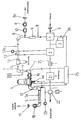
Ein Ausführungsbeispiel der Erfindung wird anhand der Zeichnung, in deren einziger Figur eine Prinzipdarstellung einer mobilen Pumpeneinheit für Wasser oder Schaum als Löschmittel wiedergegeben ist, näher erläutert.An embodiment of the invention will be explained in more detail with reference to the drawing, in the sole figure, a schematic representation of a mobile pump unit for water or foam is shown as extinguishing agent.
Die nachfolgend beschriebene mobile Pumpeneinheit ist auf einem Schlitten (nicht dargestellt) montiert und mit einer Abdeckhaube (nicht dargestellt) abgedeckt. Sie kann in einem Feuerlöschfahrzeug untergebracht werden und mittels am Schlitten angebrachter Traggriffe zum Einsatzort getragen werden. Ihre wesentlichen Funktionselemente sind eine Pumpe 1 und ein Kompressor 2, die von einem gemeinsamen Motor 3 angetrieben werden, sowie ein Schaummittel-Zumischer 4 und ein Verschäumungskanal 5.The mobile pump unit described below is mounted on a carriage (not shown) and covered with a cover (not shown). It can be accommodated in a fire truck and carried by means mounted on the carriage carrying handles to the site. Their essential functional elements are a
An die als einstufige Kreiselpumpe ausgebildete Pumpe 1 wird eine Saugleitung 6 angeschlossen, die in ein Wasserreservoir (Wassertank, natürliches Gewässer) (nicht dargestellt) reicht. Von der an die Druckseite der Pumpe 1 angeschlossenen Löschwasserleitung 8 zweigt nach einem Rückschlagventil 9 eine Druckleitung 7 ab. In die Löschwasserleitung 8 ist weiterhin ein Durchflußreduzierungselement 10 aus Kugelhahn und Stauscheibe sowie ein erstes Absperrventil 11 zur Sperrung bzw. Freigabe des Austritts von Löschwasser eingebunden. Die Druckleitung 7 führt weiter über eine Venturidüse 12 mit Manometer 12a, eine Stauscheibe 13, einen Wasserfilter 14, ein Magnetventil 15 mit integrierter Druckreduzierung/Durchflußmengenbegrenzung und einen Kugelhahn 16 zu dem Schaummittel-Zumischer 4. Von dem Schaummittel-Zumischer 4 führt die Druckleitung 7 über ein zweites Rückschlagventil 17 und den Verschäumungskanal 5 sowie ein zweites Absperrventil 18 zum Schaumausgang 19. In die Druckleitung 7 ist vor dem Verschäumungskanal 5 eine vom Kompressor 2 kommende Druckluftleitung 20 eingebunden. Die Druckluftleitung 20 führt zur Luftberuhigung über einen Luftberuhigungskessel 21. In die Druckluftleitung 20 ist ein Druckregelventil 22 mit Manometer 23 sowie eine Druckluftaustragsleitung 24 zur Versorgung anderer Druckluftverbraucher eingebunden. Die gesamte Pumpeneinheit ist an eine zentrale Entwässerung 25 angeschlossen, die mit einem einheitlichen Hebelsystem bedient werden kann, um die Anlage im wesentlichen als Ganzes zu entwässern.To the designed as a single-stage
Die Funktion der mobilen Pumpeneinheit zur Bereitstellung von Schaum und/oder Wasser an einem Brandherd wird nachfolgend beschrieben.The function of the mobile pump unit to provide foam and / or water to a source of fire is described below.
Das von der Pumpe 1 angesaugte Wasser wird in die Löschwasserleitung 8 und - sofern das erste Absperrventil geöffnet ist - zum Wasserausgang 8a gefördert. Wenn gleichzeitig mit der Bereitstellung von Löschwasser am Schaumausgang 19 auch Schaum zur Brandbekämpfung ausgetragen werden soll, wird mit dem Durchflußreduzierungselement 10 in der Löschwasserleitung 8 der Waseraustrag bei 8a reduziert, damit eine ausreichende Wassermenge zur Schaumerzeugung zur Verfügung steht.The sucked by the
Der Motor 3 ist ein Verbrennungsmotor, dessen Abgasleitung als Abgasstrahler 3a ausgebildet ist, die an der Saugseite an die Pumpe 1 angeschlossen ist, um die in der Saugleitung 6 vorhandene Luft bei der Inbetriebnahme der mobilen Pumpeneinheit abzusaugen und ein schnelles und problemloses Ansaugen von Wasser zu gewährleisten.The
Für die Schaumerzeugung wird das angesaugte Wasser weiter durch die Venturidüse 12 geleitet, die in ihrem sich konisch verengenden Raum und ihrem sich diffusorartig erweiternden Raum zur Bildung eines Kühlwasser-Kreislaufs an den Kompressor 2 angeschlossen ist. Dadurch ist auf einfache Weise eine ausreichende Kühlung des Kompressors 2 möglich. Mit Hilfe einer der Venturidüse 12 nachgeschalteten Stauscheibe 13 wird der Druck des geförderten Wassers reduziert. Mit dem anschließenden, von einem zentralen Bedienfeld (nicht dargestellt) über einen Taster "Wasser" zu betätigenden Magnetventil 15 mit integrierter Druckreduzierung und Durchflußmengenbegrenzung wird die für die Schaumerzeugung maximal erforderliche Wasserdurchflußmenge, die im Ausführungsbeispiel 170 l/min beträgt, eingestellt. Mit dem dem Zumischer 4 in der Druckleitung 7 vorgeschalteten Kugelhahn 16 wird die durchfließende Wassermenge für Nass- oder Trockenschaum (170 l/min bzw. 70 l /min) eingestellt.For the foam generation, the sucked water is passed through the Venturi 12, which is connected to the
Der Schaummittel-Zumischer 4 ist als Dosierkolbenzumischer ausgebildet. Die Einstellung der Zumischrate an Schaummittelkonzentrat erfolgt mit einem an seiner Unterseite vorgesehenen Dosierstab 4a. Der Schaummittel-Zumischer 4 ist wasserhydraulisch betrieben und saugt das Schaummittel entsprechend der eingestellten Dosiermenge aus einem Behälter (nicht dargestellt) an. Dem Schaummittel-Zumischer 4 ist in der Druckleitung 7 ein zweites Rückschlagventil 17 nachgeschaltet, das verhindert, daß die danach in die Druckleitung 7 und damit in das Wasser-Schaummittel-Gemisch über die Druckluftleitung 20 eingeführte Druckluft bzw. das jetzt gebildete Wasser-Schaummittel-Luft-Gemisch zum Schaummittel-Zumischer 4 zurückströmt. Das Wasser-Schaummittel-Luft-Gemisch (Schaum), das durch die Luftzufuhr bereits teilsweise verschäumt ist, gelangt nun in den Verschäumungskanal 5, in dem es durch in diesen eingebaute Verwirbelungselemente 5a verwirbelt und dadurch intensiv verschäumt wird.The
Der entsprechend der am Kugelhahn 16 eingestellten Wasserdurchflußmenge erzeugte Naß- oder Trockenschaum wird über das zweite Absperrventil 18 und den Schaumausgang 19 ausgetragen.The wet or dry foam produced in accordance with the water flow rate set on the
Die beschriebene mobile Pumpeneinheit kann somit gleichzeitig oder wahlweise mit Wasser oder Schaum als Löschmittel betrieben werden. Sie ist kompakt ausgebildet und tragbar und kann daher auch an unzugängliche Einsatzorte verbracht werden. Der Kompressor 2 liefert auch die erforderliche Druckluft für andere Anwendungsfälle und kann zudem dafür genutzt werden, kurzzeitig größere Wurfweiten für den über ein Strahlrohr ausgebrachten Löschschaum zu erzielen. Die Anlage verfügt über eine Bedientafel (nicht dargestellt), über die ihre Funktion von zentraler Stelle gesteuert wird. Einige der Bedienelemente des zentralen Bedientableaus sind der Einfachheit halber in der Zeichnung dargestellt. Bezugszeichen 26 bezeichnet einen Taster zum Ein- und Ausschalten des Kompressors 2. Weiterhin sind ein Taster 27 zur Betätigung des Druckregelventils 22 für die Druckluftzufuhr und ein Taster 28 für die Betätigung des Magnetventils 15 in der wasserführenden Druckleitung dargestellt. Auch das Ein- und Ausschalten des Schaummittel-Zumischers 4, die Abgabe von Naß- oder Trockenschaum durch die mit dem Kugelhahn 16 einstellbare Wassermenge, das Zu- oder Abschalten des an die Pumpe 1 angeschlossenen Abgasstrahlers 3a, das Öffnen und Schließen der Absperrventile 11 und 18 am Wasserausgang 8a und/oder Schaumausgang 19 oder die Wasserdurchflußreduzierung für die Wasserausgabe in der Löschwasserleitung 8 mit Hilfe des Durchflußreduzierungselements 10 erfolgen über die auf dem Bedienfeld angeordneten Anzeigeelemente, Schalter und Taster (nicht dargestellt).The described mobile pump unit can thus be operated simultaneously or optionally with water or foam as an extinguishing agent. It is compact and portable and can therefore be moved to inaccessible locations. The
Die Erfindung ist selbstverständlich nicht auf die zuvor beispielhaft beschriebene Ausführungsform einer Pumpeneinheit beschränkt. Im Rahmen des Grundgedankens der Erfindung, der in der Kombination der sowohl für eine Wasser- als auch eine Schaumbereitstellung erforderlichen Bauteile zu einer kompakt ausgebildeten, tragbaren Pumpeneinheit besteht, sind zahlreiche Modifikationen denkbar.Of course, the invention is not limited to the embodiment of a pump unit described above by way of example. Within the scope of the invention, which consists in combining the components required for both water and foam supply into a compact, portable pump unit, numerous modifications are conceivable.
- 11
- Pumpe (einstufige Kreiselpumpe)Pump (single-stage centrifugal pump)
- 22
- Kompressor (Kolbenkompressor)Compressor (piston compressor)
- 33
- Motor (Verbrennungsmotor)Engine (combustion engine)
- 3a3a
- AbgasstrahlpumpeExhaust jet pump
- 44
- Schaummittel-Zumischer (Dosierkolbenzumischer)Foaming agent admixer (dosing piston mixer)
- 4a4a
- Dosierstabmetering
- 55
- VerschäumungskanalVerschäumungskanal
- 5a5a
- Verwirbelungselementeturbulators
- 66
- Saugleitungsuction
- 77
- Druckleitungpressure line
- 88th
- LöschwasserleitungWater supply line
- 8a8a
- WassserausgangWassserausgang
- 99
- erstes Rückschlagventilfirst check valve
- 1010
- DurchflußreduzierungselementDurchflußreduzierungselement
- 1111
- erstes Absperrventilfirst shut-off valve
- 1212
- Venturidüseventuri
- 12a12a
- Manometer-WasserdruckPressure gauge water pressure
- 1313
- Stauscheibebaffle plate
- 1414
- Wasserfilterwater filters
- 1515
- Magnetventil mit integrierter Druckreduzierung und DurchflußmengenbegrenzungSolenoid valve with integrated pressure reduction and flow limitation
- 1616
- Kugelhahn Trocken/NaßBall valve dry / wet
- 1717
- zweites Rückschlagventilsecond check valve
- 1818
- zweites Absperrventilsecond shut-off valve
- 1919
- SchaumausgangFOAM OUTPUT
- 2020
- DruckluftleitungCompressed air line
- 2121
- LuftberuhigungskesselPlenum boiler
- 2222
- DruckregelventilPressure control valve
- 2323
- Manometer (Luftdruck)Pressure gauge (air pressure)
- 2424
- DruckluftaustragsleitungDruckluftaustragsleitung
- 2525
- zentrale Entwässerungcentral drainage
- 2626
- Taster KompressorPush button compressor
- 2727
-
Taster für Druckregelventil 22Push button for
pressure control valve 22 - 2828
-
Taster für Magnetventil 15Button for
solenoid valve 15
Claims (15)
- A mobile pump unit for fire fighting with a pump (1) for aspirating water from a water reservoir at a specific flowrate via a water fire main (8) and another pressure and flowrate-controlled pressure pipe (7) that branches off the water fire main (8) and has an integrated foam agent admixer (4) with a downstream foaming duct (5), and runs into a pressure-controlled compressed air pipe (20) connected to a compressor (2) upstream of said foaming duct (5), the pump (1) and the compressor (2) being driven by a joint engine (3) that is designed as an internal combustion engine, characterized in that the engine (3) comprises an exhaust gas jet (3a) that is connected via the pump (1) to the suction line (6) to suck off the air that is present in the suction line (6).
- The mobile pump unit according to claim 1, characterized in that a venturi nozzle (12) the nozzle part and diffusor part of which are integrated into a cooling circuit that runs via the compressor (2) is integrated into the pressure pipe (7) in the flow direction of the pump (1).
- The mobile pump unit according to claim 1, characterized in that a flow reducing element (10) is provided upstream of the water outlet (8a) in the water fire main (8) for simultaneous ejection of fire fighting water and fire fighting foam to ensure the pressure required for foam generation.
- The mobile pump unit according to claim 1, characterized in that vortexing elements (5a) are integrated into the foaming duct (5).
- The mobile pump unit according to claim 4, characterized in that said vortexing elements (5a) consist of discs attached to the periphery of a rod orientated in axial direction.
- The mobile pump unit according to claim 1, characterized in that a check valve (17) is inserted into the pressure pipe (7) before it runs into the foaming duct (5).
- The mobile pump unit according to claim 1, characterized in that a ball valve (16) for adjusting the throughput of wet and dry foam is inserted upstream of the foaming agent admixer (4).
- The mobile pump unit according to any one of claims 1 to 6, characterized in that a baffle plate (13) for pressure reduction, a water filter (14), and a solenoid valve (15) with an integrated pressure reducer and flow restrictor are inserted into the pressure pipe (7) in flow direction upstream of the foaming agent admixer (4).
- The mobile pump unit according to any one of claims 1 to 8, characterized in that a check valve (9) is inserted immediately after the pump (1) into the water fire main (8).
- The mobile pump unit according to any one of claims 1 to 9, characterized in that the compressed air line (20) for generating an even air flow is conducted across a plenum (21).
- The mobile pump unit according to any one of claims 1 to 10, characterized in that a pressure outlet line (24) for supplying other compressed air consumers is connected to the compressed air line (20) via a pressure control valve (22).
- The mobile pump unit according to any one of claims 1 to 11, characterized in that its water-conducting components are connected to a central drainage system.
- The mobile pump unit according to any one of claims 1 to 12, characterized by a central operating console on which pushbuttons are provided for switching the compressor and the foaming agent admixer on and off, for flow and pressure setting for water or compressed air to produce a specific foam quality or to ensure parallel operation of fire fighting water and foam, for releasing and/or shutting off the water and/or foam outlet and for starting the internal combustion engine as well as the respective pressure display devices for air and water pressure.
- The mobile pump unit according to any one of claims 1 to 13, characterized in that the foaming agent admixer (4) is designed as a hydraulically operated proportioning piston admixer with dosing rod (4a).
- The mobile pump unit according to any one of the preceding claims, characterized in that all functional and control components including the operating console and a cover are placed on a carriage with carrying handles.
Applications Claiming Priority (2)
| Application Number | Priority Date | Filing Date | Title |
|---|---|---|---|
| DE29903572U DE29903572U1 (en) | 1999-02-18 | 1999-02-18 | Mobile pump unit for fire fighting |
| DE29903572U | 1999-02-18 |
Publications (4)
| Publication Number | Publication Date |
|---|---|
| EP1029560A2 EP1029560A2 (en) | 2000-08-23 |
| EP1029560A3 EP1029560A3 (en) | 2002-01-02 |
| EP1029560B1 true EP1029560B1 (en) | 2007-08-08 |
| EP1029560B8 EP1029560B8 (en) | 2008-07-16 |
Family
ID=8070072
Family Applications (1)
| Application Number | Title | Priority Date | Filing Date |
|---|---|---|---|
| EP00250049A Expired - Lifetime EP1029560B8 (en) | 1999-02-18 | 2000-02-18 | Mobile pump unit for fire-fighting |
Country Status (4)
| Country | Link |
|---|---|
| EP (1) | EP1029560B8 (en) |
| AT (1) | ATE369192T1 (en) |
| DE (2) | DE29903572U1 (en) |
| ES (1) | ES2288147T3 (en) |
Families Citing this family (8)
| Publication number | Priority date | Publication date | Assignee | Title |
|---|---|---|---|---|
| AT3857U1 (en) * | 1999-10-25 | 2000-09-25 | Lenzing Technik Gmbh & Co Kg | ADDITIONAL DEVICE FOR FIRE EXTINGUISHING SYSTEMS |
| DE10132326B4 (en) * | 2001-07-02 | 2004-05-06 | Schmitz Gmbh | Fire fighting device with compressed air foam |
| EP1473061B1 (en) | 2003-04-30 | 2009-07-08 | Rassek, Bernd-Dietrich | Method for admixture (dosing) of liquid additives in fire extinguishing installations with water-based fire extinguishing agents |
| DE10343935A1 (en) * | 2003-09-23 | 2005-04-28 | Iveco Magirus | Fire fighting equipment |
| DE102004002112B4 (en) * | 2004-01-14 | 2013-10-31 | Karl Perr | Control system for a compressed air foam fire extinguishing device |
| AT501355B1 (en) * | 2005-02-08 | 2006-12-15 | Rosenbauer Int Ag | FOAM EXTRACTION DEVICE AND METHOD OF OPERATION THEREOF |
| ES2784733A1 (en) * | 2019-03-28 | 2020-09-30 | Martino Joaquin Gracia | Fire extinguishing pump for high intensity fires and high temperatures (Machine-translation by Google Translate, not legally binding) |
| NL2023888B1 (en) * | 2019-09-24 | 2021-04-13 | Hytrans Beheer B V | MOBILE PUMP SYSTEM WITH DOSING PUMP AND METHOD FOR THIS |
Citations (1)
| Publication number | Priority date | Publication date | Assignee | Title |
|---|---|---|---|---|
| US5582776A (en) * | 1995-03-28 | 1996-12-10 | The Snuffer Corporation | Apparatus for generating foam |
Family Cites Families (3)
| Publication number | Priority date | Publication date | Assignee | Title |
|---|---|---|---|---|
| GB831720A (en) * | 1958-09-23 | 1960-03-30 | Kronenburg N V Geb | Improvements in or relating to fire extinguishing installations |
| CH595850A5 (en) * | 1975-05-02 | 1978-02-28 | Vogt Ag Oberdiessbach | Fire fighting equipment with hand held nozzles |
| DE29811105U1 (en) * | 1998-01-22 | 1998-09-10 | Vigh Andreas Dipl Ing Fh | Stepless automatic mechanical foam dosing system for high and normal pressure fire-fighting centrifugal pumps |
-
1999
- 1999-02-18 DE DE29903572U patent/DE29903572U1/en not_active Expired - Lifetime
-
2000
- 2000-02-18 DE DE50014534T patent/DE50014534D1/en not_active Expired - Fee Related
- 2000-02-18 AT AT00250049T patent/ATE369192T1/en not_active IP Right Cessation
- 2000-02-18 EP EP00250049A patent/EP1029560B8/en not_active Expired - Lifetime
- 2000-02-18 ES ES00250049T patent/ES2288147T3/en not_active Expired - Lifetime
Patent Citations (1)
| Publication number | Priority date | Publication date | Assignee | Title |
|---|---|---|---|---|
| US5582776A (en) * | 1995-03-28 | 1996-12-10 | The Snuffer Corporation | Apparatus for generating foam |
Also Published As
| Publication number | Publication date |
|---|---|
| EP1029560B8 (en) | 2008-07-16 |
| ATE369192T1 (en) | 2007-08-15 |
| DE50014534D1 (en) | 2007-09-20 |
| EP1029560A2 (en) | 2000-08-23 |
| EP1029560A3 (en) | 2002-01-02 |
| DE29903572U1 (en) | 1999-07-08 |
| ES2288147T3 (en) | 2008-01-01 |
Similar Documents
| Publication | Publication Date | Title |
|---|---|---|
| EP1663504B1 (en) | Cleaning lance | |
| EP1259296B1 (en) | Mixing chamber for producing compressed air foam for extinguishing devices | |
| DE3517284C2 (en) | Method and device for producing and dispensing extinguishing agents mixed with an additive | |
| DE102004032020B4 (en) | Process and arrangement for the production of compressed air foam for fire fighting and decontamination | |
| EP1029560B1 (en) | Mobile pump unit for fire-fighting | |
| EP3337576A1 (en) | Fire extinguisher | |
| DE3740677C2 (en) | ||
| EP1632272B1 (en) | Tunnel with a pressurised air foam fire extinguishing system | |
| EP2105166A1 (en) | Device for fighting fires in a vehicle | |
| EP1273321B1 (en) | Device for fire fighting with pressurised air foam | |
| DE4415709C2 (en) | Mixer for foaming agents | |
| EP1016469A1 (en) | Drain cleaning pistol | |
| DE19650171C1 (en) | Abrasive sand-blasting appliance for use with dry or wet sand | |
| DE19521536A1 (en) | Spray gun for both high and low pressure cleaning | |
| CH201450A (en) | Air foam generator. | |
| AT523064B1 (en) | Method and liquid mixing system for providing a liquid-foam mixture | |
| EP0266495B1 (en) | Powder-extinguishing installation for fire engines | |
| DE4209353A1 (en) | Abrasive water jet gun - has wet sand feed pipe with opening through which surrounding air is drawn to mix with sand and reduce viscosity, thereby improving jet efficiency | |
| DE19908224B4 (en) | Gas-charged hot air generator for room heating | |
| DE4029354C1 (en) | Fire extinguisher generating foam - incorporates separate tanks for water, foaming agent and pressurised gas | |
| DE3933582A1 (en) | Mixing nozzle for producing foam for fire-fighting - has mixing chamber with side connection for foam producing medium | |
| AT142276B (en) | Foam extinguishing system. | |
| DE202012003752U1 (en) | Device for producing foam | |
| AT4223U1 (en) | DEVICE FOR ADDING A COMPRESSED GAS TO A FOAMING EXTINGUISHING LIQUID | |
| AT158686B (en) | Air foam generator. |
Legal Events
| Date | Code | Title | Description |
|---|---|---|---|
| PUAI | Public reference made under article 153(3) epc to a published international application that has entered the european phase |
Free format text: ORIGINAL CODE: 0009012 |
|
| AK | Designated contracting states |
Kind code of ref document: A2 Designated state(s): AT BE CH CY DE DK ES FI FR GB GR IE IT LI LU MC NL PT SE |
|
| AX | Request for extension of the european patent |
Free format text: AL;LT;LV;MK;RO;SI |
|
| PUAL | Search report despatched |
Free format text: ORIGINAL CODE: 0009013 |
|
| AK | Designated contracting states |
Kind code of ref document: A3 Designated state(s): AT BE CH CY DE DK ES FI FR GB GR IE IT LI LU MC NL PT SE |
|
| AX | Request for extension of the european patent |
Free format text: AL;LT;LV;MK;RO;SI |
|
| 17P | Request for examination filed |
Effective date: 20011203 |
|
| AKX | Designation fees paid |
Free format text: AT BE CH CY DE DK ES FI FR GB GR IE IT LI LU MC NL PT SE |
|
| 17Q | First examination report despatched |
Effective date: 20050318 |
|
| GRAP | Despatch of communication of intention to grant a patent |
Free format text: ORIGINAL CODE: EPIDOSNIGR1 |
|
| GRAS | Grant fee paid |
Free format text: ORIGINAL CODE: EPIDOSNIGR3 |
|
| GRAA | (expected) grant |
Free format text: ORIGINAL CODE: 0009210 |
|
| AK | Designated contracting states |
Kind code of ref document: B1 Designated state(s): AT BE CH CY DE DK ES FI FR GB GR IE IT LI LU MC NL PT SE |
|
| REG | Reference to a national code |
Ref country code: GB Ref legal event code: FG4D Free format text: NOT ENGLISH |
|
| REG | Reference to a national code |
Ref country code: CH Ref legal event code: EP |
|
| REG | Reference to a national code |
Ref country code: IE Ref legal event code: FG4D Free format text: LANGUAGE OF EP DOCUMENT: GERMAN |
|
| GBT | Gb: translation of ep patent filed (gb section 77(6)(a)/1977) |
Effective date: 20070820 |
|
| REF | Corresponds to: |
Ref document number: 50014534 Country of ref document: DE Date of ref document: 20070920 Kind code of ref document: P |
|
| ET | Fr: translation filed | ||
| REG | Reference to a national code |
Ref country code: CH Ref legal event code: NV Representative=s name: ANDRE ROLAND S.A. |
|
| REG | Reference to a national code |
Ref country code: ES Ref legal event code: FG2A Ref document number: 2288147 Country of ref document: ES Kind code of ref document: T3 |
|
| PG25 | Lapsed in a contracting state [announced via postgrant information from national office to epo] |
Ref country code: FI Free format text: LAPSE BECAUSE OF FAILURE TO SUBMIT A TRANSLATION OF THE DESCRIPTION OR TO PAY THE FEE WITHIN THE PRESCRIBED TIME-LIMIT Effective date: 20070808 |
|
| REG | Reference to a national code |
Ref country code: CH Ref legal event code: PUE Owner name: SOGEPI S.A. Free format text: SCHMITZ GMBH#FEUERWEHR- UND UMWELTTECHNIK, RUDOLF-BREITSCHEID-STRASSE 78#14943 LUCKENWALDE (DE) -TRANSFER TO- SOGEPI S.A.#RUE DE LA FLAMME 66, C/O JAWER (NEUCHATEL) SA#2108 COUVET (CH) |
|
| REG | Reference to a national code |
Ref country code: IE Ref legal event code: FD4D |
|
| PG25 | Lapsed in a contracting state [announced via postgrant information from national office to epo] |
Ref country code: GR Free format text: LAPSE BECAUSE OF FAILURE TO SUBMIT A TRANSLATION OF THE DESCRIPTION OR TO PAY THE FEE WITHIN THE PRESCRIBED TIME-LIMIT Effective date: 20071109 Ref country code: DK Free format text: LAPSE BECAUSE OF FAILURE TO SUBMIT A TRANSLATION OF THE DESCRIPTION OR TO PAY THE FEE WITHIN THE PRESCRIBED TIME-LIMIT Effective date: 20070808 |
|
| PG25 | Lapsed in a contracting state [announced via postgrant information from national office to epo] |
Ref country code: IE Free format text: LAPSE BECAUSE OF FAILURE TO SUBMIT A TRANSLATION OF THE DESCRIPTION OR TO PAY THE FEE WITHIN THE PRESCRIBED TIME-LIMIT Effective date: 20070808 Ref country code: PT Free format text: LAPSE BECAUSE OF FAILURE TO SUBMIT A TRANSLATION OF THE DESCRIPTION OR TO PAY THE FEE WITHIN THE PRESCRIBED TIME-LIMIT Effective date: 20080108 |
|
| NLS | Nl: assignments of ep-patents |
Owner name: SOGEPI S.A. Effective date: 20080410 |
|
| PLBE | No opposition filed within time limit |
Free format text: ORIGINAL CODE: 0009261 |
|
| STAA | Information on the status of an ep patent application or granted ep patent |
Free format text: STATUS: NO OPPOSITION FILED WITHIN TIME LIMIT |
|
| REG | Reference to a national code |
Ref country code: CH Ref legal event code: NV Representative=s name: ANDRE ROLAND S.A. |
|
| PG25 | Lapsed in a contracting state [announced via postgrant information from national office to epo] |
Ref country code: SE Free format text: LAPSE BECAUSE OF FAILURE TO SUBMIT A TRANSLATION OF THE DESCRIPTION OR TO PAY THE FEE WITHIN THE PRESCRIBED TIME-LIMIT Effective date: 20071108 |
|
| 26N | No opposition filed |
Effective date: 20080509 |
|
| REG | Reference to a national code |
Ref country code: FR Ref legal event code: CA |
|
| BERE | Be: lapsed |
Owner name: *SCHMITZ G.M.B.H. FEUERWERK- UND UMWELTTECHNIK Effective date: 20080228 |
|
| PG25 | Lapsed in a contracting state [announced via postgrant information from national office to epo] |
Ref country code: MC Free format text: LAPSE BECAUSE OF NON-PAYMENT OF DUE FEES Effective date: 20080228 |
|
| REG | Reference to a national code |
Ref country code: ES Ref legal event code: PC2A |
|
| REG | Reference to a national code |
Ref country code: CH Ref legal event code: PLI Owner name: ONE SEVEN OF GERMANY GMBH Free format text: SOGEPI S.A.#RUE DE LA FLAMME 66, C/O JAWER (NEUCHATEL) SA#2108 COUVET (CH) -TRANSFER TO- ONE SEVEN OF GERMANY GMBH#RUDOLF-BREITSCHEID-STR. 78#14943 LUCKENWALDE (DE) |
|
| PG25 | Lapsed in a contracting state [announced via postgrant information from national office to epo] |
Ref country code: BE Free format text: LAPSE BECAUSE OF NON-PAYMENT OF DUE FEES Effective date: 20080228 |
|
| REG | Reference to a national code |
Ref country code: GB Ref legal event code: 732E Free format text: REGISTERED BETWEEN 20090326 AND 20090401 |
|
| PGFP | Annual fee paid to national office [announced via postgrant information from national office to epo] |
Ref country code: LU Payment date: 20090225 Year of fee payment: 10 Ref country code: AT Payment date: 20090227 Year of fee payment: 10 Ref country code: ES Payment date: 20090326 Year of fee payment: 10 |
|
| NLUE | Nl: licence registered with regard to european patents |
Effective date: 20090211 |
|
| PGFP | Annual fee paid to national office [announced via postgrant information from national office to epo] |
Ref country code: NL Payment date: 20090223 Year of fee payment: 10 |
|
| PGFP | Annual fee paid to national office [announced via postgrant information from national office to epo] |
Ref country code: CH Payment date: 20090224 Year of fee payment: 10 Ref country code: GB Payment date: 20090225 Year of fee payment: 10 |
|
| PG25 | Lapsed in a contracting state [announced via postgrant information from national office to epo] |
Ref country code: CY Free format text: LAPSE BECAUSE OF FAILURE TO SUBMIT A TRANSLATION OF THE DESCRIPTION OR TO PAY THE FEE WITHIN THE PRESCRIBED TIME-LIMIT Effective date: 20070808 |
|
| PGFP | Annual fee paid to national office [announced via postgrant information from national office to epo] |
Ref country code: IT Payment date: 20090223 Year of fee payment: 10 Ref country code: DE Payment date: 20090327 Year of fee payment: 10 |
|
| REG | Reference to a national code |
Ref country code: ES Ref legal event code: GD2A Effective date: 20090820 |
|
| PGFP | Annual fee paid to national office [announced via postgrant information from national office to epo] |
Ref country code: FR Payment date: 20090220 Year of fee payment: 10 |
|
| REG | Reference to a national code |
Ref country code: NL Ref legal event code: V1 Effective date: 20100901 |
|
| REG | Reference to a national code |
Ref country code: CH Ref legal event code: PL |
|
| GBPC | Gb: european patent ceased through non-payment of renewal fee |
Effective date: 20100218 |
|
| PG25 | Lapsed in a contracting state [announced via postgrant information from national office to epo] |
Ref country code: LI Free format text: LAPSE BECAUSE OF NON-PAYMENT OF DUE FEES Effective date: 20100228 Ref country code: CH Free format text: LAPSE BECAUSE OF NON-PAYMENT OF DUE FEES Effective date: 20100228 |
|
| REG | Reference to a national code |
Ref country code: FR Ref legal event code: ST Effective date: 20101029 |
|
| PG25 | Lapsed in a contracting state [announced via postgrant information from national office to epo] |
Ref country code: AT Free format text: LAPSE BECAUSE OF NON-PAYMENT OF DUE FEES Effective date: 20100218 |
|
| PG25 | Lapsed in a contracting state [announced via postgrant information from national office to epo] |
Ref country code: NL Free format text: LAPSE BECAUSE OF NON-PAYMENT OF DUE FEES Effective date: 20100901 Ref country code: FR Free format text: LAPSE BECAUSE OF NON-PAYMENT OF DUE FEES Effective date: 20100301 |
|
| PG25 | Lapsed in a contracting state [announced via postgrant information from national office to epo] |
Ref country code: DE Free format text: LAPSE BECAUSE OF NON-PAYMENT OF DUE FEES Effective date: 20100901 |
|
| REG | Reference to a national code |
Ref country code: ES Ref legal event code: FD2A Effective date: 20110323 |
|
| PG25 | Lapsed in a contracting state [announced via postgrant information from national office to epo] |
Ref country code: IT Free format text: LAPSE BECAUSE OF NON-PAYMENT OF DUE FEES Effective date: 20100218 Ref country code: GB Free format text: LAPSE BECAUSE OF NON-PAYMENT OF DUE FEES Effective date: 20100218 |
|
| PG25 | Lapsed in a contracting state [announced via postgrant information from national office to epo] |
Ref country code: ES Free format text: LAPSE BECAUSE OF NON-PAYMENT OF DUE FEES Effective date: 20110310 |
|
| PG25 | Lapsed in a contracting state [announced via postgrant information from national office to epo] |
Ref country code: ES Free format text: LAPSE BECAUSE OF NON-PAYMENT OF DUE FEES Effective date: 20100219 |
|
| PG25 | Lapsed in a contracting state [announced via postgrant information from national office to epo] |
Ref country code: LU Free format text: LAPSE BECAUSE OF NON-PAYMENT OF DUE FEES Effective date: 20100218 |