EP1028540A2 - Spreizspektrumempfänger mit Entspreizern verteilt unter RAKE-Kombinatoren - Google Patents
Spreizspektrumempfänger mit Entspreizern verteilt unter RAKE-Kombinatoren Download PDFInfo
- Publication number
- EP1028540A2 EP1028540A2 EP00102621A EP00102621A EP1028540A2 EP 1028540 A2 EP1028540 A2 EP 1028540A2 EP 00102621 A EP00102621 A EP 00102621A EP 00102621 A EP00102621 A EP 00102621A EP 1028540 A2 EP1028540 A2 EP 1028540A2
- Authority
- EP
- European Patent Office
- Prior art keywords
- despreaders
- spread spectrum
- multipath components
- rake
- groups
- Prior art date
- Legal status (The legal status is an assumption and is not a legal conclusion. Google has not performed a legal analysis and makes no representation as to the accuracy of the status listed.)
- Withdrawn
Links
Images


Classifications
-
- H—ELECTRICITY
- H04—ELECTRIC COMMUNICATION TECHNIQUE
- H04B—TRANSMISSION
- H04B1/00—Details of transmission systems, not covered by a single one of groups H04B3/00 - H04B13/00; Details of transmission systems not characterised by the medium used for transmission
- H04B1/69—Spread spectrum techniques
- H04B1/707—Spread spectrum techniques using direct sequence modulation
- H04B1/7097—Interference-related aspects
- H04B1/711—Interference-related aspects the interference being multi-path interference
- H04B1/7115—Constructive combining of multi-path signals, i.e. RAKE receivers
- H04B1/7117—Selection, re-selection, allocation or re-allocation of paths to fingers, e.g. timing offset control of allocated fingers
-
- H—ELECTRICITY
- H04—ELECTRIC COMMUNICATION TECHNIQUE
- H04B—TRANSMISSION
- H04B7/00—Radio transmission systems, i.e. using radiation field
- H04B7/02—Diversity systems; Multi-antenna system, i.e. transmission or reception using multiple antennas
- H04B7/04—Diversity systems; Multi-antenna system, i.e. transmission or reception using multiple antennas using two or more spaced independent antennas
- H04B7/06—Diversity systems; Multi-antenna system, i.e. transmission or reception using multiple antennas using two or more spaced independent antennas at the transmitting station
- H04B7/0602—Diversity systems; Multi-antenna system, i.e. transmission or reception using multiple antennas using two or more spaced independent antennas at the transmitting station using antenna switching
-
- H—ELECTRICITY
- H04—ELECTRIC COMMUNICATION TECHNIQUE
- H04B—TRANSMISSION
- H04B2201/00—Indexing scheme relating to details of transmission systems not covered by a single group of H04B3/00 - H04B13/00
- H04B2201/69—Orthogonal indexing scheme relating to spread spectrum techniques in general
- H04B2201/707—Orthogonal indexing scheme relating to spread spectrum techniques in general relating to direct sequence modulation
- H04B2201/70707—Efficiency-related aspects
- H04B2201/7071—Efficiency-related aspects with dynamic control of receiver resources
Definitions
- the present invention relates generally to spread spectrum receivers, and more specifically to a spread spectrum receiver where multiple RAKE combiners are provided for multiple users.
- a transmitted radio signal is reflected off objects, causing radio waves of multipath reflections to arrive on a receive site at different times depending on the lengths of the propagation paths.
- CDMA code division multiple access
- more than one cell-site transmitter uses the same PN code for modulating a signal and transmit the spread spectrum signal simultaneously on the same carrier frequency.
- a mobile site is able to take advantage of the characteristic of the PN modulation by despreading a received signal with mutually delayed PN codes of the same sequence and maximal-ratio combining the despread multipath signals using what is known as a RAKE combiner to produce a high level signal. It is therefore desirable to provide RAKE combining as many component signals as there are propagation paths for a received spread spectrum signal.
- the number of propagation paths a single spread spectrum signal may take varies significantly depending on the particular multipath environment of the signal.
- a known multi-user spread spectrum RAKE receiver is comprised of a plurality of despreaders and a plurality of RAKE combiners. These RAKE combiners are provided in a one-to-one correspondence to multiple users. Because of the presence of multipath components in a received spread spectrum signal, a fixed number of despreaders are provided for each user. Usually, five to 10 despreaders are provided for each user. Since the number of such multipath components is determined by the number (J) of cell-site transmitters which a single receiver can detect, a total number (J x M) of despreaders is required for a multi-user receiver, where M is the number of its users.
- This object is obtained by sharing a plurality of despreaders among multiple RAKE combiners.
- a spread spectrum receiver comprising a plurality of despreaders and a plurality of RAKE combiners associated respectively with multiple users to which a plurality of spread spectrum signals are transmitted respectively.
- Allocation circuitry is provided for detecting one or more multipath components of received spread spectrum signals and allocating the despreaders to the RAKE combiners according to the detected one or more multipath components. All despreaders are provided in number that is smaller than the number of the RAKE combiners times a maximum number of possible multipath components of each spread spectrum signal and greater than the number of said RAKE combiners.
- the allocation circuitry is arranged to configure the plurality of despreaders into a plurality of groups corresponding to received spread spectrum signals, with each group having one or more despreaders corresponding to the detected one or more multipath components of each of the received spread spectrum signals, and allocate the despreaders of each group to a corresponding one of the RAKE combiners.
- a multi-user CDMA (code division multiple access) RAKE receiver of the present invention for receiving a number of spread spectrum signals respectively destined for M users.
- the spread spectrum signals directed to the multiple users of the spread spectrum receiver are transmitted from one or more sources such as cell-site base transmitters.
- a transmitted signal propagates over a plurality of paths of different (lengths) propagation delay times, or multipath fading channels.
- multipath channels For a given spread spectrum signal, there may be as many multipath channels as there are cell-site transmitters or only one propagation path, depending on the multipath environment of the spread spectrum signal.
- the spread spectrum receiver includes a plurality of despreaders 11 1 through 11 K , all of which are connected to the antenna 10 to receive spread spectrum signals destined for the users of the receiver.
- Each despreader includes a correlator 20 and a variable delay element 21 to produce a despread signal.
- the correlator 20 of each despreader is supplied with a pseudonoise (PN) code sequence via the variable delay element 21 for correlating the spread spectrum signals from antenna 10 with the PN code sequence.
- PN pseudonoise
- the variable delay element 21 is supplied with an externally supplied delay time value determined by the length of a particular multipath fading channel. Thus, there is at least one delay time value for each PN code sequence depending on multipath environment of each transmitted spread spectrum signal.
- Selectors 12 1 ⁇ 12 M are provided respectively for M users, each selector having K input terminals connected to the outputs of despreaders 11 1 ⁇ 11 K respectively and J output terminals, where J is the number of cell-site transmitters, or a maximum number of multipath fading channels of each user signal.
- RAKE combiners, or adders 13 1 ⁇ 13 M are associated with the selectors 12 1 ⁇ 12 M , respectively.
- Each adder 13 has J input terminals connected to the outputs of the associated selector 12 to combine output signals from an allocated group of despreaders whose number varies depending on the number of paths over which the spread spectrum signal of the associated user is actually propagated.
- each adder 13 the selected multipath signals are weighted by optimum coefficients and maximal-ratio combined to produce a high level output in a manner known in the art.
- the integer K is greater than M and smaller than J x M.
- the multiple users are assigned pseudonoise codes PN 1 ⁇ PN M, respectively.
- all despreaders 11 are configured into a plurality of groups corresponding in number to the multiple users, or RAKE combiners 13 1 ⁇ 13 M .
- the number of despreaders in each group may differ from each other depending on the number of multipath components of the corresponding spread spectrum signal (i.e., multiple propagation paths the spread spectrum signal take during transmission).
- the selectors 12 are controlled to establish one or more connections between its K input terminals and its J output terminals so that each selector 12 supplies the output signals from a group of despreaders to the associated adder 13, where the multipath components of the corresponding spread spectrum signal are RAKE combined.
- the output of each adder 13 is supplied to one of decision devices 14 1 ⁇ 14 M that is connected to the associated user, where the RAKE combined signal is compared to a decision threshold to produce a demodulated signal for the associated user.
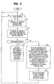
- control processor proceeds as shown in the flowchart of Fig. 2.
- the processor determines the number of all received spread spectrum signals including the currently received signal (step 202) and determines the number of multipath components of the currently received spread spectrum signal from the outputs of searchers 15 (step 203).
- the control processor checks to see if despreaders are available for allocation to the RAKE combiner corresponding to the currently received spread spectrum signal.
- step 204 If the decision at step 204 is affirmative, flow proceeds to step 205 to allocate despreaders to that RAKE combiner corresponding to the detected multipath components of the spread spectrum signal.
- the control processor returns to the starting point of the routine.
- step 204 If the decision at step 204 is negative, flow proceeds to step 206 to configure all despreaders into a plurality of groups corresponding to the received spread spectrum signals according to the number of multipath components of each received spread spectrum signal and the relative strengths of the multipath components, so that each group has one or more despreaders substantially corresponding to the detected multipath components of the spread spectrum signal.
- control processor allocates despreaders to the RAKE combiners according to the configured groups, and returns to the starting point of the routine.
- All despreaders 11 are therefore efficiently utilized to be commonly shared by M users.
- the number of despreaders allocated to each user varies from time to time depending on multipath fading environment of the propagation path. Therefore, a despreader allocated to a particular user at a given instant of time may be reallocated to another user at the next instant.
- the allocation of despreaders and delay time values is performed by a plurality of searchers 15 1 ⁇ 15 M , a control processor 16, a switch 17, a PN code generator 18 and a time data memory 19, with the aid of the selectors 12 1 ⁇ 12 M .
- Searchers 15 are provided in number corresponding to the M users.
- Each searcher includes a correlator 25, and a variable delay element 26 which introduces a constantly varying delay time to the PN code of the associated user supplied from the PN code generator 18. This delay time is cyclically swept across a range of delay time values in order to search for multipath components.
- the spread spectrum signals from antenna 10 are despread with each user's PN code of constantly varying phase and one or more significant peaks will be detected when the varying phase coincides with multipath signal components.
- the pseudonoise generator 18 produces a plurality of different pseudonoise code sequences PN 1 through PN M corresponding respectively to the multiple users and supplies these PN codes respectively to the searchers 15 and to the switch 17.
- Time data memory 19 provides delay time values t 1 ⁇ t n to the switch 17.
- the switch 17 establishes connections to the despreaders from the PN generator 18 and the time data memory 19 so that the despreaders of each group are supplied with the PN code of the associated user and delay time values.
- Despreaders allocated to each user are therefore supplied with the user's PN code and respectively loaded with different delay time values corresponding to the propagation paths of the spread spectrum signal destined for the user.
- the switch 17 may be reconfigured according to varying propagation paths and their varying path lengths so that despreaders previously assigned to one user are reassigned to another user.
- the present invention achieves a savings of despreaders. If the maximum number of multipath channels for each user signal (usually determined by the number of accessible cell-site transmitters) is denoted as J and the average number of multipath channels allocated to each user is denoted as A, the RAKE receiver of this invention achieves a J-to-A savings of despreaders and associated circuits.
- Fig. 3 is a block diagram of a second embodiment of the present invention.
- the time-serial outputs of searchers 15 1 ⁇ 15 M are converted to parallel signals in respective tapped delay lines 31 1 ⁇ 30 M and compared in comparators 31 1 ⁇ 31 M with the parallel outputs of adders 12 1 ⁇ 12 M .
- the output of each comparator 31 represents the timing differences of the actually recovered multipath signals from the multipath signals detected by the corresponding searcher 15.
- the output of each comparator 31 is supplied to the control processor 16 as a feedback signal.
- Control processor 16 uses the feedback signals from the comparators 31 to reconfigure the switch 17. Precision feedback control is therefore achieved.
- Fig. 4 shows a further embodiment of the present invention in which a number of diversity antennas 40 1 ⁇ 40 N are used, instead of the single antenna 10.
- Antenna switches 41 1 ⁇ 41 K are associated respectively with despreaders 11 1 ⁇ 11 K .
- Each of the antenna switches 41 has N input terminals respectively connected to the antennas 40 1 ⁇ 40 N and a single output terminal connected to the input of the associated despreader.
- a diversity controller 42 receives all signals detected by the antennas 40 1 ⁇ 40 N and the users' PN code sequences PN 1 ⁇ PN M from PN generator 18 to control the switches 41 1 ⁇ 41 K .
- the diversity controller 42 includes a plurality of searcher units 50 1 ⁇ 50 M associated respectively with the M users.
- Each searcher unit comprises searchers 53 1 ⁇ 53 N identical in structure to the searchers 15 used in Fig. 3.
- Searcher units 50 1 ⁇ 50 M are supplied with PN codes PN 1 through PN M, respectively.
- Searchers 53 1 ⁇ 53 N of each unit are connected respectively to the antennas 40 1 ⁇ 40 N to despread the respective antenna signals with the same PN code, so that each searcher unit produces a plurality of outputs each containing a series of multipath components of the signal destined for the user associated with the searcher unit.
- Maximum selectors 51 1 ⁇ 51 M are associated respectively with the searcher units 50 1 ⁇ 50 M to receive the output signals of the searchers of the associated unit.
- Each maximum selector makes a search through the despread signals of all antennas and selects one having the multipath component of highest strength and applies all multipath components of the selected signal to a controller 52 in addition to the identity of the selected antenna. All outputs of the maximum selectors 51 1 ⁇ 51 M are analyzed by the controller 52 and the number of significant multipath components is determined for each user and the selected antenna. Controller 52-individually operates the switches 41 1 ⁇ 41 K by allocating them to the selected antennas so that each selected antenna is connected through a number of switches 41 to the associated despreaders.
Landscapes
- Engineering & Computer Science (AREA)
- Computer Networks & Wireless Communication (AREA)
- Signal Processing (AREA)
- Mobile Radio Communication Systems (AREA)
- Noise Elimination (AREA)
- Radio Transmission System (AREA)
- Stereo-Broadcasting Methods (AREA)
Applications Claiming Priority (2)
| Application Number | Priority Date | Filing Date | Title |
|---|---|---|---|
| JP3044899A JP2000232430A (ja) | 1999-02-08 | 1999-02-08 | Rake(熊手)受信機 |
| JP3044899 | 1999-02-08 |
Publications (2)
| Publication Number | Publication Date |
|---|---|
| EP1028540A2 true EP1028540A2 (de) | 2000-08-16 |
| EP1028540A3 EP1028540A3 (de) | 2001-02-21 |
Family
ID=12304208
Family Applications (1)
| Application Number | Title | Priority Date | Filing Date |
|---|---|---|---|
| EP20000102621 Withdrawn EP1028540A3 (de) | 1999-02-08 | 2000-02-08 | Spreizspektrumempfänger mit Entspreizern verteilt unter RAKE-Kombinatoren |
Country Status (5)
| Country | Link |
|---|---|
| EP (1) | EP1028540A3 (de) |
| JP (1) | JP2000232430A (de) |
| KR (1) | KR100364035B1 (de) |
| CN (1) | CN1126306C (de) |
| BR (1) | BR0000493A (de) |
Cited By (14)
| Publication number | Priority date | Publication date | Assignee | Title |
|---|---|---|---|---|
| EP1158688A1 (de) * | 2000-05-25 | 2001-11-28 | Lucent Technologies Inc. | Dynamische Fingerzuweisung für Rake-Empfänger |
| GB2381714A (en) * | 2001-11-02 | 2003-05-07 | Toshiba Res Europ Ltd | Flexible rake receiver with configurable correlation |
| WO2003088515A1 (en) | 2002-04-12 | 2003-10-23 | Interdigital Technology Corporation | Path searcher using reconfigurable correlator sets |
| KR100427577B1 (ko) * | 2001-12-27 | 2004-04-28 | 한국전자통신연구원 | 하드웨어 복잡도를 줄인 레이크 수신기 |
| WO2004040791A1 (de) * | 2002-10-31 | 2004-05-13 | Infineon Technologies Ag | Vorrichtung und verfahren zur rake-demodulation von signalen mit freier zuordnung zwischen spreizcode-generatoren und rake-fingern |
| EP1246371A3 (de) * | 2001-03-31 | 2004-05-19 | Alcatel | Verfahren und Vorrichtung zum dynamischen verteilen der Korrelator-Ressourcen eines funkbasierten CDMA Kommunikationssystems |
| DE10306301B3 (de) * | 2003-02-14 | 2004-10-07 | Infineon Technologies Ag | Vorrichtung zur Erzeugung von Spreizcodes in einem Mobilfunksystem und deren Verwendung in einem CDMA-Übertragungssystem |
| EP1376887A4 (de) * | 2001-04-02 | 2004-11-17 | Mitsubishi Electric Corp | Mehrbenutzer-demodulationsvorrichtung, empfangsvorrichtung und mehrkanal-demodulationsverfahren |
| US7092432B2 (en) | 2002-04-12 | 2006-08-15 | Interdigital Technology Corporation | Node-B/base station rake finger pooling |
| CN100361413C (zh) * | 2004-06-03 | 2008-01-09 | 电子科技大学 | 一种直接序列扩频信号的解扩方法 |
| US7372895B2 (en) | 2004-12-08 | 2008-05-13 | Telefonaktiebolaget Lm Ericsson (Publ) | Method of and system for delay estimation with minimized finger allocation |
| US7480356B2 (en) | 2004-12-08 | 2009-01-20 | Telefonaktiebolaget L M Ericsson (Publ) | Method of and system for path selection in rich multipath conditions |
| US7586974B2 (en) | 2004-10-19 | 2009-09-08 | Telefonaktiebolaget L M Ericsson (Publ) | Method and apparatus for rake finger allocation in a DS-CDMA receiver |
| EP2107706A1 (de) * | 2008-04-02 | 2009-10-07 | Telefonaktiebolaget LM Ericsson (publ) | Empfänger und Verfahren für die mobile Kommunikation |
Families Citing this family (4)
| Publication number | Priority date | Publication date | Assignee | Title |
|---|---|---|---|---|
| US6104709A (en) * | 1998-07-17 | 2000-08-15 | Motorola, Inc. | Channel assignment within a broad-band communication system |
| JP4096724B2 (ja) * | 2002-12-12 | 2008-06-04 | 日本電気株式会社 | マルチビームアンテナ受信装置およびマルチビーム受信方法 |
| WO2005076492A1 (ja) * | 2004-02-03 | 2005-08-18 | Matsushita Electric Industrial Co., Ltd. | Rake受信装置およびrake受信方法 |
| CN101351979B (zh) * | 2006-06-22 | 2012-06-13 | 中兴通讯股份有限公司 | Cdma下行接收信号的解调方法及其多径分配的优化方法 |
Family Cites Families (2)
| Publication number | Priority date | Publication date | Assignee | Title |
|---|---|---|---|---|
| FI932605A7 (fi) * | 1993-06-07 | 1994-12-08 | Nokia Telecommunications Oy | Tukiasemavastaanotinlaitteisto |
| JP2820918B2 (ja) * | 1996-03-08 | 1998-11-05 | 株式会社ワイ・アール・ピー移動通信基盤技術研究所 | スペクトル拡散通信装置 |
-
1999
- 1999-02-08 JP JP3044899A patent/JP2000232430A/ja active Pending
-
2000
- 2000-02-02 CN CN00100743A patent/CN1126306C/zh not_active Expired - Fee Related
- 2000-02-07 KR KR1020000005556A patent/KR100364035B1/ko not_active Expired - Fee Related
- 2000-02-08 BR BR0000493-6A patent/BR0000493A/pt not_active IP Right Cessation
- 2000-02-08 EP EP20000102621 patent/EP1028540A3/de not_active Withdrawn
Cited By (21)
| Publication number | Priority date | Publication date | Assignee | Title |
|---|---|---|---|---|
| EP1158688A1 (de) * | 2000-05-25 | 2001-11-28 | Lucent Technologies Inc. | Dynamische Fingerzuweisung für Rake-Empfänger |
| EP1246371A3 (de) * | 2001-03-31 | 2004-05-19 | Alcatel | Verfahren und Vorrichtung zum dynamischen verteilen der Korrelator-Ressourcen eines funkbasierten CDMA Kommunikationssystems |
| EP1575182A3 (de) * | 2001-04-02 | 2005-10-05 | Mitsubishi Denki Kabushiki Kaisha | Mehrbenutzer-Demodulationsvorrichtung, Empfangsvorrichtung und Mehrkanal-Demodulationsverfahren |
| EP1376887A4 (de) * | 2001-04-02 | 2004-11-17 | Mitsubishi Electric Corp | Mehrbenutzer-demodulationsvorrichtung, empfangsvorrichtung und mehrkanal-demodulationsverfahren |
| GB2397986B (en) * | 2001-11-02 | 2004-12-15 | Toshiba Res Europ Ltd | Receiver processing system |
| GB2381714B (en) * | 2001-11-02 | 2004-07-07 | Toshiba Res Europ Ltd | Receiver processing system |
| GB2397986A (en) * | 2001-11-02 | 2004-08-04 | Toshiba Res Europ Ltd | Flexible Rake receiver with variable delay means |
| GB2381714A (en) * | 2001-11-02 | 2003-05-07 | Toshiba Res Europ Ltd | Flexible rake receiver with configurable correlation |
| KR100427577B1 (ko) * | 2001-12-27 | 2004-04-28 | 한국전자통신연구원 | 하드웨어 복잡도를 줄인 레이크 수신기 |
| US7082286B2 (en) | 2002-04-12 | 2006-07-25 | Interdigital Technology Corporation | Path searcher using reconfigurable correlator sets |
| WO2003088515A1 (en) | 2002-04-12 | 2003-10-23 | Interdigital Technology Corporation | Path searcher using reconfigurable correlator sets |
| EP1495550A4 (de) * | 2002-04-12 | 2006-07-12 | Interdigital Tech Corp | Wegesucher mit umkonfigurierbaren korrelatormengen |
| US7092432B2 (en) | 2002-04-12 | 2006-08-15 | Interdigital Technology Corporation | Node-B/base station rake finger pooling |
| US7630690B2 (en) | 2002-04-12 | 2009-12-08 | Interdigital Technology Corp. | Access burst detector correlator pool |
| WO2004040791A1 (de) * | 2002-10-31 | 2004-05-13 | Infineon Technologies Ag | Vorrichtung und verfahren zur rake-demodulation von signalen mit freier zuordnung zwischen spreizcode-generatoren und rake-fingern |
| DE10306301B3 (de) * | 2003-02-14 | 2004-10-07 | Infineon Technologies Ag | Vorrichtung zur Erzeugung von Spreizcodes in einem Mobilfunksystem und deren Verwendung in einem CDMA-Übertragungssystem |
| CN100361413C (zh) * | 2004-06-03 | 2008-01-09 | 电子科技大学 | 一种直接序列扩频信号的解扩方法 |
| US7586974B2 (en) | 2004-10-19 | 2009-09-08 | Telefonaktiebolaget L M Ericsson (Publ) | Method and apparatus for rake finger allocation in a DS-CDMA receiver |
| US7372895B2 (en) | 2004-12-08 | 2008-05-13 | Telefonaktiebolaget Lm Ericsson (Publ) | Method of and system for delay estimation with minimized finger allocation |
| US7480356B2 (en) | 2004-12-08 | 2009-01-20 | Telefonaktiebolaget L M Ericsson (Publ) | Method of and system for path selection in rich multipath conditions |
| EP2107706A1 (de) * | 2008-04-02 | 2009-10-07 | Telefonaktiebolaget LM Ericsson (publ) | Empfänger und Verfahren für die mobile Kommunikation |
Also Published As
| Publication number | Publication date |
|---|---|
| BR0000493A (pt) | 2000-10-24 |
| EP1028540A3 (de) | 2001-02-21 |
| JP2000232430A (ja) | 2000-08-22 |
| CN1126306C (zh) | 2003-10-29 |
| CN1263390A (zh) | 2000-08-16 |
| KR100364035B1 (ko) | 2002-12-11 |
| KR20000071333A (ko) | 2000-11-25 |
Similar Documents
| Publication | Publication Date | Title |
|---|---|---|
| KR100235978B1 (ko) | 스펙트럼 확산 통신 수신기 | |
| EP1028540A2 (de) | Spreizspektrumempfänger mit Entspreizern verteilt unter RAKE-Kombinatoren | |
| CA2213654C (en) | Rake receiver | |
| JP3162400B2 (ja) | ベース・ステーション受信装置 | |
| US6252864B1 (en) | CDMA communication apparatus and CDMA communication method | |
| KR19990023878A (ko) | Ds-cdma 수신기 및 순방향 링크 다이버시티 방법 | |
| US20070224996A1 (en) | Wireless base station device and path search method | |
| JPH11261531A (ja) | Ds―cdmaシステムにおいて干渉抑圧のための通信装置および方法 | |
| US7382821B2 (en) | Method and apparatus for configuring a RAKE receiver | |
| US6377614B1 (en) | Spreading code synchronization circuit and method | |
| JP2001069041A (ja) | デジタル無線リンクを提供する装置、通信システム、動作させる方法、受信機及びサーチャー。 | |
| EP1424791A1 (de) | Interferenzwellenleistungsmessvorrichtung, sendeleistungssteuervorrichtung und verfahren | |
| US7200133B2 (en) | Rake finger receiver and method therefor in a spread spectrum communication system | |
| US6959070B2 (en) | Radio base station apparatus and radio communication method | |
| KR100584337B1 (ko) | 이동통신 시스템에서 셀 탐색 및 다중경로 탐색 장치 및방법 | |
| EP1044516A2 (de) | Tstd-sender mit ausgleich der antennensendeleistung und steuerverfahren dafür für basisstation in einem mobilen kommunikationssystem | |
| US6665282B1 (en) | Method and apparatus for configuring a RAKE receiver | |
| JP3380435B2 (ja) | Rake受信装置 | |
| JP3836856B2 (ja) | 無線装置 |
Legal Events
| Date | Code | Title | Description |
|---|---|---|---|
| PUAI | Public reference made under article 153(3) epc to a published international application that has entered the european phase |
Free format text: ORIGINAL CODE: 0009012 |
|
| AK | Designated contracting states |
Kind code of ref document: A2 Designated state(s): DE GB |
|
| AX | Request for extension of the european patent |
Free format text: AL;LT;LV;MK;RO;SI |
|
| PUAL | Search report despatched |
Free format text: ORIGINAL CODE: 0009013 |
|
| 17P | Request for examination filed |
Effective date: 20001215 |
|
| AK | Designated contracting states |
Kind code of ref document: A3 Designated state(s): AT BE CH CY DE DK ES FI FR GB GR IE IT LI LU MC NL PT SE |
|
| AX | Request for extension of the european patent |
Free format text: AL;LT;LV;MK;RO;SI |
|
| AKX | Designation fees paid |
Free format text: DE GB |
|
| STAA | Information on the status of an ep patent application or granted ep patent |
Free format text: STATUS: THE APPLICATION HAS BEEN WITHDRAWN |
|
| 18W | Application withdrawn |
Effective date: 20031010 |