EP1028498B1 - Steckverbinder für Koaxialkabel mit glattem Aussenleiter - Google Patents
Steckverbinder für Koaxialkabel mit glattem Aussenleiter Download PDFInfo
- Publication number
- EP1028498B1 EP1028498B1 EP00101073A EP00101073A EP1028498B1 EP 1028498 B1 EP1028498 B1 EP 1028498B1 EP 00101073 A EP00101073 A EP 00101073A EP 00101073 A EP00101073 A EP 00101073A EP 1028498 B1 EP1028498 B1 EP 1028498B1
- Authority
- EP
- European Patent Office
- Prior art keywords
- connector
- clamping
- segments
- cable
- cable conductor
- Prior art date
- Legal status (The legal status is an assumption and is not a legal conclusion. Google has not performed a legal analysis and makes no representation as to the accuracy of the status listed.)
- Expired - Lifetime
Links
- 239000004020 conductor Substances 0.000 title claims description 32
- 239000011324 bead Substances 0.000 claims description 3
- 238000003780 insertion Methods 0.000 claims description 3
- 230000037431 insertion Effects 0.000 claims description 3
- 230000004323 axial length Effects 0.000 claims description 2
- 238000006073 displacement reaction Methods 0.000 claims description 2
- 210000003128 head Anatomy 0.000 description 19
- 241000538562 Banjos Species 0.000 description 14
- 229910052751 metal Inorganic materials 0.000 description 3
- 239000002184 metal Substances 0.000 description 3
- 238000010276 construction Methods 0.000 description 2
- 238000009434 installation Methods 0.000 description 2
- 229910000838 Al alloy Inorganic materials 0.000 description 1
- RYGMFSIKBFXOCR-UHFFFAOYSA-N Copper Chemical compound [Cu] RYGMFSIKBFXOCR-UHFFFAOYSA-N 0.000 description 1
- 229910000881 Cu alloy Inorganic materials 0.000 description 1
- 238000005452 bending Methods 0.000 description 1
- 230000005540 biological transmission Effects 0.000 description 1
- 239000010949 copper Substances 0.000 description 1
- 230000006866 deterioration Effects 0.000 description 1
- 230000018109 developmental process Effects 0.000 description 1
- 239000006260 foam Substances 0.000 description 1
- 239000011888 foil Substances 0.000 description 1
- 210000001061 forehead Anatomy 0.000 description 1
- 230000013011 mating Effects 0.000 description 1
- 238000000034 method Methods 0.000 description 1
- 239000007787 solid Substances 0.000 description 1
- 230000001360 synchronised effect Effects 0.000 description 1
Images


Classifications
-
- H—ELECTRICITY
- H01—ELECTRIC ELEMENTS
- H01R—ELECTRICALLY-CONDUCTIVE CONNECTIONS; STRUCTURAL ASSOCIATIONS OF A PLURALITY OF MUTUALLY-INSULATED ELECTRICAL CONNECTING ELEMENTS; COUPLING DEVICES; CURRENT COLLECTORS
- H01R9/00—Structural associations of a plurality of mutually-insulated electrical connecting elements, e.g. terminal strips or terminal blocks; Terminals or binding posts mounted upon a base or in a case; Bases therefor
- H01R9/03—Connectors arranged to contact a plurality of the conductors of a multiconductor cable, e.g. tapping connections
- H01R9/05—Connectors arranged to contact a plurality of the conductors of a multiconductor cable, e.g. tapping connections for coaxial cables
- H01R9/0527—Connection to outer conductor by action of a resilient member, e.g. spring
Definitions
- the invention relates to a connector in the preamble of claim 1.
- a connector is known from DE-A-35 22 736. It includes one Plug head on the cable end of a Plug sleeve is turned on and thereby a pressure ring or a clamping cone against the annular surface in the recess of the Pushes sleeve between this ring surface and the corresponding surface of the pressure ring or the clamping cone the crimped end of the outer cable clamp.
- This connector is for field mounting only conditionally suitable because it consists of several, individually to be assembled one after the other and in the correct order Sharing exists.
- Coaxial cable for commercial applications especially for Transfer of larger services, on the other hand, have one massive, screw or ring-corrugated outer conductor, which without Deterioration of the electrical properties of the cable gives a certain flexibility.
- Connector developed in the pre-assembled state without previous disassembly mounted on the end of the coaxial cable can be what, especially at exposed assembly sites such as Antenna masts and the like a considerable time and Safety gain during assembly (see DE 43 43 229 C2).
- the invention has for its object a connector of the genre specified in the introduction, that it is on a coaxial cable with a smooth cable outer conductor can be dismantled without disassembly.
- This task is the introductory step for a connector mentioned type according to the invention solved by a for enclosing of the outer cable certain contact sleeve, the radially resilient segments with thickened ends and in the unloaded Condition has an inside diameter that is in the range the thickened ends of the segments smaller than the diameter of the flared end area of the outer cable and is larger than this diameter in the remaining area, and by a banjo bolt that surrounds the contact sleeve and after covering a span by turning in an internal thread of the recess of the plug head the segments the contact sleeve loaded in the clamping direction, so that this the flared end area of the outer cable against the ring surface in the recess of the plug head can jam.
- This connector can be delivered pre-assembled be that he only up to the prepared cable end must be pushed to the stop. Then he needs Installer only screw the banjo bolt into the plug head, until a prescribed tightening torque is reached is, which indicates that a sufficiently firm clamping of the Cable outer conductor has occurred. Nevertheless, the fitter can the connector, if necessary, also by complete Disassemble the banjo bolt from the plug head.
- the connector according to the invention in the Installation on a coaxial cable with a smooth outer conductor same advantages as a connector that can be assembled without disassembly for coaxial cables with corrugated outer conductor.
- the connector has a device that Clamping path of the banjo bolt is divided into two sections, by which the first a pre-assembled state of the connector and the second, its final assembly on the cable correspond (claim 2). If the installer detects the connector completely disassembled, or completely disassemble this facility enables him to Plug connectors back in the correct, factory-set Bring pre-assembly condition, the prerequisite for correct installation on the cable.
- the device for structuring the clamping path of the banjo bolt can consist of an O-ring in an annular groove lies, which is arranged so that the O-ring at the end of first span section on the cable end edge of the plug head and over the second span section is taken into the plug head (claim 3).
- This execution of the facility for structuring the The tensioning path is structurally particularly simple.
- the o-ring can simultaneously seal between the plug head and form the banjo bolt.
- the banjo bolt has a cable side following the annular groove over an axial length that at least equal to the length of the second span section is an outer diameter that is smaller than the inner diameter the recess of the plug head on its cable side End is (claim 4).
- the inner wall can be used to facilitate the assembly process the inside of the banjo bolt is a radially protruding one Shoulder that has a stop for a collar of the ring Contact sleeve forms and in the pre-assembled state of the connector limits the displacement of the contact sleeve that between the annular surface and the segments of the contact sleeve an insertion gap for the end area of the cable outer conductor remains (claim 5).
- projecting shoulder of the banjo bolt can be another take on another function, namely that of transmission of the thrust of the banjo bolt on the contact sleeve.
- the shoulder of the hollow screw is on best as a continuous or interrupted ring shoulder trained, the plug-side end face at the end of second clamping path section the clamping force on the thickened Formed ends of the segments of the contact sleeve Transmits counter surfaces (claim 6).
- the cable 1 shows a coaxial cable of a newer type. It comprises a tubular inner conductor 1, a cable dielectric 2, usually a foam dielectric, a smooth outer cable 3 made of a copper or aluminum alloy and a cable sheath 4 made of plastic.
- the cable outer conductor 3 has a crimped end region 32, here in a conical shape, with the largest diameter D 1 .
- the flaring can also be flange-shaped at right angles.
- the cable including the cable jacket 4 has an outer diameter D 2 .
- the diameter D 1 must be less than or at most equal to the diameter D 2 because, as will be explained, the cable sheath extends into the connector, the latter at least at its cable end Must have inner diameter D 2 .
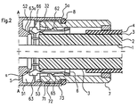
- the connector shown in Fig. 2 in longitudinal section comprises a plug head 5, a contact sleeve 6, one of these enclosing hollow screw 7 and one in an annular groove 73 the hollow screw 7 lying O-ring 8. From the plug head 5 is only this in this figure and in the other figures for electrical contacting and mechanical clamping of the Cable outer conductor 3 formed part shown. To the left of the dashed line A-A, the plug head 5 one of the have usual, known constructions, which after the direct the respective application. Nor can he shown connector inner conductor after any, Principle known in the prior art with the inner cable 1 mechanically and electrically connected and in particular be contacted according to the plug / socket principle. This is not the subject of the invention.
- Fig. 2 shows the connector in the pre-assembled state.
- the O-ring 8 is just on the cable side Front edge 5a of the plug head 5, while the external thread 72 of the hollow screw 7 in the first threads of Internal thread 53 in the recess 51 of the plug head 5 intervenes.
- the connector is already on the coaxial cable postponed, etc. until the first palpable Resistance occurs. This is caused by the fact that the Front edge of the crimped end portion 32 of the cable outer conductor 3 against a run-up surface 63b (see FIG.
- the conical ring surface 63a has a few more tenth of a millimeter high, circumferential bead 66 on the after mounting on the outside of the flared end area 32 of the cable outer conductor 3 comes to rest there digs in a bit and thereby the mechanical clamping and electrical contacting improved and over the scope uniform. The latter is achieving a big one Intermodulation distance useful.
- the banjo bolt 7 is inserted into the plug head 5 turned, etc. against the resistance of yourself deforming O-rings 8.
- the contact sleeve 6 is initially still displaceable in the axial direction around the second clamping path section b, which is equal to the distance between the mating end face 71a of the ring shoulder 71 of the banjo bolt 7 to the thickened ends 63 of the segments 62 of the contact sleeve 6 trained counter surfaces 63c.
- This Metal ring 9 primarily acts on the cable Bending forces, so that this at least largely from the Contacting point, that is between the surfaces 52 and 63 a (see FIG. 2) clamped, crimped end region 32 of the outer cable can be kept away.
- a tight connection between the cable and the connector can e.g. with a shrink tube. This is known and therefore not shown.
Landscapes
- Coupling Device And Connection With Printed Circuit (AREA)
Description
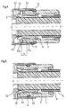
- Fig. 1
- das Ende eines Koaxialkabels im Längsschnitt,
- Fig. 2 bis 5
- den kabelseitigen Teil eines Ausführungsbeispiels eines Steckverbinders nach der Erfindung, in verschiedenen Montagezuständen.
Claims (8)
- Steckverbinder für einen glatten Außenleiter (3) aufweisende Koaxialkabel, mit einem Steckerkopf (5), der eine Ausnehmung (51) mit einer Ringfläche (52) zur innenseitigen Kontaktierung eines aufgebördelten Endbereiches (32) des Kabelaußenleiters (3) hat, gekennzeichnet durch eine zum Umschließen des Kabelaußenleites bestimmte Kontakthülse (6), die radial federnde Segmente (62) mit verdickten Enden (63) und im unbelasteten Zustand einen Innendurchmesser hat, der im Bereich der verdickten Enden (63) der Segmente (62) kleiner als der Durchmesser (D1) des aufgebördelten Endbereiches (32) des Kabelaußenleiters (3) und im übrigen Bereich größer als dieser Durchmesser (D1) ist, und durch eine Hohlschraube (7), welche die Kontakthülse (6) umgibt und nach dem Zurücklegen eines Spannweges durch Eindrehen in ein Innengewinde der Ausnehmung (51) des Steckerkopfes (5) die Segmente (62) der Kontakthülse (6) in Spannrichtung belastet, so daß diese den aufgebördelten Endbereich (32) des Kabelaußenleiters (3) gegen die Ringfläche (52) in der Ausnehmung (51) des Steckerkopfes (5) klemmen kann.
- Steckverbinder nach Anspruch 1, gekennzeichnet durch eine Einrichtung, die den Spannweg der Hohlschraube (7) in zwei Abschnitte gliedert, von denen der erste einem vormontierten Zustand des Steckverbinders und der zweite dessen Endmontage auf dem Kabel entsprechen.
- Steckverbinder nach Anspruch 2, dadurch gekennzeichnet, daß die Einrichtung zur Gliederung des Spannweges der Hohlschraube (7) aus einem O-Ring (8) besteht, der in einer Ringnut (73) liegt, die so angeordnet ist, daß der O-Ring (8) am Ende des ersten Spannwegabschnittes auf den kabelseitigen Stirnrand des Steckerkopfes (5) aufläuft und über den zweiten Spannwegabschnitt in den Steckerkopf hinein mitgenommen wird.
- Steckverbinder nach Anspruch 3, dadurch gekennzeichnet, daß die Hohlschraube (7) kabelseitig anschließend an die Ringnut (73) über eine axiale Länge, die mindestens gleich der Länge des zweiten Spannwegabschnittes ist, eine Außendurchmesser hat, der kleiner als der Innendurchmesser der Ausnehmung (51) des Steckerkopfes (5) an seinem kabelseitigen Ende ist.
- Steckverbinder nach einem der Ansprüche 1 bis 4, dadurch gekennzeichnet, daß die Innenwand der Hohlschraube (7) innenseitig eine radial einspringende Schulter (71) hat, die einen Anschlag für einen Ringbund (65) der Kontakthülse (6) bildet und im vormontierten Zustand des Steckverbinders den Verschiebeweg der Kontakthülse (6) so begrenzt, daß zwischen der Ringfläche (52) und den Segmenten (62) der Kontakthülse (6) ein Einführspalt (s) für den Endbereich (32) des Kabelaußenleiters (3) verbleibt.
- Steckverbinder nach Anspruch 5, dadurch gekennzeichnet, daß die einspringende Schulter der Hohlschraube (7) eine Ringschulter (71) ist, deren steckseitige Stirnfläche (71a) am Ende des zweiten Spannwegabschnittes die Spannkraft auf an den verdickten Enden (63) der Segmente (62) der Kontakthülse (6) ausgebildete Gegenflächen (63c) überträgt.
- Steckverbinder nach einem der Ansprüche 1 bis 6, dadurch gekennzeichnet, daß an den verdickten Enden (63) der Segmente (62) der Kontakthülse (6) jeweils eine auf einer Kegelmantelfläche liegende Auflauffläche (63b) für den Stirnrand des Kabelaußenleiters (3) ausgebildet ist und daß der Kegelwinkel so gewählt ist, daß die Segmente bei Überschreitung einer gewissen, von dem Stirnrand des Kabelaußenleiters (3) auf die Auflaufflächen (63b) ausgeübten Axialkraft radial auffedern.
- Steckverbinder nach einem der Ansprüche 1 bis 7, dadurch gekennzeichnet, daß mindestens eine der zur Klemmung des Endbereiches (32) des Kabelaußenleiters (3) bestimmten Flächen (52, 63a) mindestens einen Wulst (66) zur Verbesserung der Klemmung und Kontaktierung hat.
Priority Applications (1)
| Application Number | Priority Date | Filing Date | Title |
|---|---|---|---|
| DK00101073T DK1028498T3 (da) | 1999-02-10 | 2000-01-20 | Stikforbinder for et koaksialkabel med glat yderleder |
Applications Claiming Priority (2)
| Application Number | Priority Date | Filing Date | Title |
|---|---|---|---|
| DE19906023 | 1999-02-10 | ||
| DE19906023 | 1999-02-10 |
Publications (2)
| Publication Number | Publication Date |
|---|---|
| EP1028498A1 EP1028498A1 (de) | 2000-08-16 |
| EP1028498B1 true EP1028498B1 (de) | 2004-11-24 |
Family
ID=7897390
Family Applications (1)
| Application Number | Title | Priority Date | Filing Date |
|---|---|---|---|
| EP00101073A Expired - Lifetime EP1028498B1 (de) | 1999-02-10 | 2000-01-20 | Steckverbinder für Koaxialkabel mit glattem Aussenleiter |
Country Status (4)
| Country | Link |
|---|---|
| US (1) | US6383019B1 (de) |
| EP (1) | EP1028498B1 (de) |
| DE (1) | DE50008711D1 (de) |
| DK (1) | DK1028498T3 (de) |
Families Citing this family (24)
| Publication number | Priority date | Publication date | Assignee | Title |
|---|---|---|---|---|
| CN103178365B (zh) | 2000-05-10 | 2018-04-17 | 托马斯及贝茨国际股份有限公司 | 具有可拆卸锁定套的同轴连接器 |
| DK1303005T3 (da) * | 2001-10-10 | 2005-05-02 | Corning Cabelcon As | Inderledersystem |
| ATE336808T1 (de) * | 2002-06-22 | 2006-09-15 | Spinner Gmbh Elektrotech | Koaxialer steckverbinder |
| US6802739B2 (en) | 2003-01-16 | 2004-10-12 | Corning Gilbert Inc. | Coaxial cable connector |
| US6733336B1 (en) | 2003-04-03 | 2004-05-11 | John Mezzalingua Associates, Inc. | Compression-type hard-line connector |
| US7261581B2 (en) | 2003-12-01 | 2007-08-28 | Corning Gilbert Inc. | Coaxial connector and method |
| US7044785B2 (en) * | 2004-01-16 | 2006-05-16 | Andrew Corporation | Connector and coaxial cable with outer conductor cylindrical section axial compression connection |
| US6955562B1 (en) | 2004-06-15 | 2005-10-18 | Corning Gilbert Inc. | Coaxial connector with center conductor seizure |
| DE202004014843U1 (de) * | 2004-09-23 | 2004-11-18 | Rosenberger Hochfrequenztechnik Gmbh & Co. Kg | Koaxialsteckverbinder und Außenleiterkontakthülse für diesen |
| US8157589B2 (en) | 2004-11-24 | 2012-04-17 | John Mezzalingua Associates, Inc. | Connector having a conductively coated member and method of use thereof |
| US7077700B2 (en) | 2004-12-20 | 2006-07-18 | Corning Gilbert Inc. | Coaxial connector with back nut clamping ring |
| US7275957B1 (en) * | 2006-03-22 | 2007-10-02 | Andrew Corporation | Axial compression electrical connector for annular corrugated coaxial cable |
| US7435135B2 (en) * | 2007-02-08 | 2008-10-14 | Andrew Corporation | Annular corrugated coaxial cable connector with polymeric spring finger nut |
| US8171629B2 (en) | 2007-12-21 | 2012-05-08 | Commscope Inc. Of North Carolina | Reuseable coaxial connector method |
| US7740502B2 (en) * | 2007-12-21 | 2010-06-22 | Commscope, Inc. Of North Carolina | Reuseable coaxial connectors and related methods |
| US20100064857A1 (en) * | 2008-09-15 | 2010-03-18 | Commscope, Inc. Of North Carolina | Coaxial cable end preparation tool and related methods |
| US20100064522A1 (en) * | 2008-09-15 | 2010-03-18 | Commscope, Inc. Of North Carolina | Coaxial cable end preparation tool with drive shaft and related methods |
| US20100275341A1 (en) * | 2009-04-29 | 2010-11-04 | Ansell Healthcare Products Llc | Knitted Glove Having A Single Layer With A Plurality Of Yarns |
| US9017101B2 (en) | 2011-03-30 | 2015-04-28 | Ppc Broadband, Inc. | Continuity maintaining biasing member |
| US8172608B2 (en) | 2010-04-29 | 2012-05-08 | Commscope Inc. Of North Carolina | Reuseable coaxial connectors and related extraction tools and methods |
| US8337229B2 (en) | 2010-11-11 | 2012-12-25 | John Mezzalingua Associates, Inc. | Connector having a nut-body continuity element and method of use thereof |
| US8366481B2 (en) | 2011-03-30 | 2013-02-05 | John Mezzalingua Associates, Inc. | Continuity maintaining biasing member |
| US9017102B2 (en) * | 2012-02-06 | 2015-04-28 | John Mezzalingua Associates, LLC | Port assembly connector for engaging a coaxial cable and an outer conductor |
| US10404048B2 (en) * | 2013-11-26 | 2019-09-03 | Commscope Technologies Llc | Adapter for sealing cover for electrical interconnections |
Family Cites Families (8)
| Publication number | Priority date | Publication date | Assignee | Title |
|---|---|---|---|---|
| FR1402025A (fr) * | 1964-04-27 | 1965-06-11 | Superflexit | Perfectionnements aux raccords pour conduits souples et dispositifs analogues |
| DE3522736C1 (de) * | 1985-06-25 | 1987-02-19 | Spinner Gmbh Elektrotech | Vorrichtung zum druckdichten Verbinden des Aussenleiters einer Koaxialleitung |
| US5137470A (en) * | 1991-06-04 | 1992-08-11 | Andrew Corporation | Connector for coaxial cable having a helically corrugated inner conductor |
| DE4343229C2 (de) * | 1993-06-01 | 1995-04-13 | Spinner Gmbh Elektrotech | Steckverbinder für Wellrohrkoaxialkabel |
| US5595502A (en) * | 1995-08-04 | 1997-01-21 | Andrew Corporation | Connector for coaxial cable having hollow inner conductor and method of attachment |
| DE19734236C2 (de) * | 1996-09-14 | 2000-03-23 | Spinner Gmbh Elektrotech | Koaxialkabel-Steckverbinder |
| US5766037A (en) * | 1996-10-11 | 1998-06-16 | Radio Frequency Systems, Inc. | Connector for a radio frequency cable |
| DE19729876C2 (de) * | 1997-07-11 | 1999-11-11 | Spinner Gmbh Elektrotech | Steckverbinder für Koaxialkabel |
-
2000
- 2000-01-20 DK DK00101073T patent/DK1028498T3/da active
- 2000-01-20 EP EP00101073A patent/EP1028498B1/de not_active Expired - Lifetime
- 2000-01-20 DE DE50008711T patent/DE50008711D1/de not_active Expired - Fee Related
- 2000-02-10 US US09/501,252 patent/US6383019B1/en not_active Expired - Fee Related
Also Published As
| Publication number | Publication date |
|---|---|
| US6383019B1 (en) | 2002-05-07 |
| DE50008711D1 (de) | 2004-12-30 |
| EP1028498A1 (de) | 2000-08-16 |
| DK1028498T3 (da) | 2005-01-03 |
Similar Documents
| Publication | Publication Date | Title |
|---|---|---|
| EP1028498A1 (de) | Steckverbinder für Koaxialkabel mit glattem Aussenleiter | |
| EP0494438B1 (de) | Vorrichtung für den Anschluss eines Kabelendes | |
| DE69500741T2 (de) | Mikrominiatur-Koaxialverbinder mit Schnappbefestigung | |
| DE69307662T2 (de) | Koaxialer Verbinder für gewellten Rohrleiter | |
| DE60225672T2 (de) | Kabelverschraubungszusammenbau | |
| EP0897202B1 (de) | Steckverbinder für Koaxialkabel | |
| DE3141966C2 (de) | ||
| DE69713200T2 (de) | Elektrische Verbinderanordnung mit Koaxialkabel mit gewelltem Aussenleiter | |
| DE69704203T2 (de) | Verfahren zum verbinden von koaxialkabeln und dazu gehöriger stecker | |
| DE602004008654T2 (de) | Coaxialverbinder mit verbessertem isolationsglied und assoziiertes verfahren | |
| DE102004004567B3 (de) | Steckverbinder für Koaxialkabel mit ringgewelltem Außenleiter | |
| EP0901200B1 (de) | Steckverbinder für Koaxialkabel mit ringgewelltem Aussenleiter | |
| EP1810374A1 (de) | Kabelstecker für ein koaxialkabel sowie verfahren zum montieren eines solchen kabelsteckers | |
| DE19815157A1 (de) | Steckverbinder für Koaxialkabel | |
| DE4343229A1 (de) | Steckverbinder für Wellrohrkoaxialkabel | |
| DE2647043C2 (de) | Zugentlastungsvorrichtung für eine Kabeleinführung in ein Gehäuse eines elektrischen Gerätes | |
| DE102009035995A1 (de) | Verbindungseinrichtung für Hochspannungskabel | |
| DE4224673C2 (de) | Kabelstecker | |
| DE4300243C1 (de) | Koaxialer 7/16-Buchsensteckverbinder | |
| DE69622668T2 (de) | Kabelend-Verbindungsanordnung | |
| DE3935360C2 (de) | ||
| DE19528235A1 (de) | Vorrichtung zur Verbindung der Abschirmung eines Kabels mit dem Gehäuse eines elektrischen Verbinders | |
| EP1657795A1 (de) | Kabelsteckverbinder einer Steckverbindungseinrichtung für die Mittel- und Hochspannungstechnik | |
| EP4092835B1 (de) | Elektrischer steckverbinder, elektrische steckverbinderanordnung und elektrische steckverbindung | |
| EP0918370A2 (de) | Koaxialverbinder |
Legal Events
| Date | Code | Title | Description |
|---|---|---|---|
| PUAI | Public reference made under article 153(3) epc to a published international application that has entered the european phase |
Free format text: ORIGINAL CODE: 0009012 |
|
| AK | Designated contracting states |
Kind code of ref document: A1 Designated state(s): DE DK FI FR GB IT SE |
|
| AX | Request for extension of the european patent |
Free format text: AL;LT;LV;MK;RO;SI |
|
| 17P | Request for examination filed |
Effective date: 20000720 |
|
| 17Q | First examination report despatched |
Effective date: 20001030 |
|
| AKX | Designation fees paid |
Free format text: DE DK FI FR GB IT SE |
|
| GRAH | Despatch of communication of intention to grant a patent |
Free format text: ORIGINAL CODE: EPIDOS IGRA |
|
| GRAS | Grant fee paid |
Free format text: ORIGINAL CODE: EPIDOSNIGR3 |
|
| GRAA | (expected) grant |
Free format text: ORIGINAL CODE: 0009210 |
|
| AK | Designated contracting states |
Kind code of ref document: B1 Designated state(s): DE DK FI FR GB IT SE |
|
| REG | Reference to a national code |
Ref country code: GB Ref legal event code: FG4D Free format text: NOT ENGLISH |
|
| REG | Reference to a national code |
Ref country code: SE Ref legal event code: TRGR |
|
| REF | Corresponds to: |
Ref document number: 50008711 Country of ref document: DE Date of ref document: 20041230 Kind code of ref document: P |
|
| REG | Reference to a national code |
Ref country code: DK Ref legal event code: T3 |
|
| GBT | Gb: translation of ep patent filed (gb section 77(6)(a)/1977) |
Effective date: 20050322 |
|
| ET | Fr: translation filed | ||
| PLBI | Opposition filed |
Free format text: ORIGINAL CODE: 0009260 |
|
| PLAF | Information modified related to communication of a notice of opposition and request to file observations + time limit |
Free format text: ORIGINAL CODE: EPIDOSCOBS2 |
|
| PLAX | Notice of opposition and request to file observation + time limit sent |
Free format text: ORIGINAL CODE: EPIDOSNOBS2 |
|
| 26 | Opposition filed |
Opponent name: WILHELM SIHN JR. GMBH & CO. KGWILHELM-SIHN-STR Effective date: 20050824 |
|
| RAP2 | Party data changed (patent owner data changed or rights of a patent transferred) |
Owner name: SPINNER GMBH |
|
| PLBB | Reply of patent proprietor to notice(s) of opposition received |
Free format text: ORIGINAL CODE: EPIDOSNOBS3 |
|
| REG | Reference to a national code |
Ref country code: FR Ref legal event code: CD |
|
| PLAY | Examination report in opposition despatched + time limit |
Free format text: ORIGINAL CODE: EPIDOSNORE2 |
|
| PLBC | Reply to examination report in opposition received |
Free format text: ORIGINAL CODE: EPIDOSNORE3 |
|
| PLAL | Information related to reply to examination report in opposition modified |
Free format text: ORIGINAL CODE: EPIDOSCORE3 |
|
| PLAB | Opposition data, opponent's data or that of the opponent's representative modified |
Free format text: ORIGINAL CODE: 0009299OPPO |
|
| R26 | Opposition filed (corrected) |
Opponent name: WILHELM SIHN JR. GMBH & CO. KG WILHELM-SIHN-STRASS Effective date: 20050824 |
|
| PLCK | Communication despatched that opposition was rejected |
Free format text: ORIGINAL CODE: EPIDOSNREJ1 |
|
| PGFP | Annual fee paid to national office [announced via postgrant information from national office to epo] |
Ref country code: DK Payment date: 20080124 Year of fee payment: 9 |
|
| PLBN | Opposition rejected |
Free format text: ORIGINAL CODE: 0009273 |
|
| STAA | Information on the status of an ep patent application or granted ep patent |
Free format text: STATUS: OPPOSITION REJECTED |
|
| PGFP | Annual fee paid to national office [announced via postgrant information from national office to epo] |
Ref country code: DE Payment date: 20071213 Year of fee payment: 9 Ref country code: FI Payment date: 20080122 Year of fee payment: 9 Ref country code: GB Payment date: 20080123 Year of fee payment: 9 Ref country code: IT Payment date: 20080126 Year of fee payment: 9 Ref country code: SE Payment date: 20080124 Year of fee payment: 9 |
|
| 27O | Opposition rejected |
Effective date: 20071207 |
|
| PGFP | Annual fee paid to national office [announced via postgrant information from national office to epo] |
Ref country code: FR Payment date: 20080118 Year of fee payment: 9 |
|
| EUG | Se: european patent has lapsed | ||
| GBPC | Gb: european patent ceased through non-payment of renewal fee |
Effective date: 20090120 |
|
| REG | Reference to a national code |
Ref country code: DK Ref legal event code: EBP |
|
| PG25 | Lapsed in a contracting state [announced via postgrant information from national office to epo] |
Ref country code: DE Free format text: LAPSE BECAUSE OF NON-PAYMENT OF DUE FEES Effective date: 20090801 Ref country code: FI Free format text: LAPSE BECAUSE OF NON-PAYMENT OF DUE FEES Effective date: 20090120 |
|
| REG | Reference to a national code |
Ref country code: FR Ref legal event code: ST Effective date: 20091030 |
|
| PG25 | Lapsed in a contracting state [announced via postgrant information from national office to epo] |
Ref country code: GB Free format text: LAPSE BECAUSE OF NON-PAYMENT OF DUE FEES Effective date: 20090120 |
|
| PG25 | Lapsed in a contracting state [announced via postgrant information from national office to epo] |
Ref country code: FR Free format text: LAPSE BECAUSE OF NON-PAYMENT OF DUE FEES Effective date: 20090202 |
|
| PG25 | Lapsed in a contracting state [announced via postgrant information from national office to epo] |
Ref country code: DK Free format text: LAPSE BECAUSE OF NON-PAYMENT OF DUE FEES Effective date: 20090731 |
|
| PG25 | Lapsed in a contracting state [announced via postgrant information from national office to epo] |
Ref country code: IT Free format text: LAPSE BECAUSE OF NON-PAYMENT OF DUE FEES Effective date: 20090120 |
|
| PG25 | Lapsed in a contracting state [announced via postgrant information from national office to epo] |
Ref country code: SE Free format text: LAPSE BECAUSE OF NON-PAYMENT OF DUE FEES Effective date: 20090121 |