EP1028342A1 - Device for pivoting an object, e.g. an optical element, around two orthogonal axes - Google Patents
Device for pivoting an object, e.g. an optical element, around two orthogonal axes Download PDFInfo
- Publication number
- EP1028342A1 EP1028342A1 EP00102490A EP00102490A EP1028342A1 EP 1028342 A1 EP1028342 A1 EP 1028342A1 EP 00102490 A EP00102490 A EP 00102490A EP 00102490 A EP00102490 A EP 00102490A EP 1028342 A1 EP1028342 A1 EP 1028342A1
- Authority
- EP
- European Patent Office
- Prior art keywords
- axis
- inner ring
- coupling
- axes
- support
- Prior art date
- Legal status (The legal status is an assumption and is not a legal conclusion. Google has not performed a legal analysis and makes no representation as to the accuracy of the status listed.)
- Granted
Links
- 230000003287 optical effect Effects 0.000 title claims description 32
- 230000008878 coupling Effects 0.000 claims abstract description 70
- 238000010168 coupling process Methods 0.000 claims abstract description 70
- 238000005859 coupling reaction Methods 0.000 claims abstract description 70
- 230000005540 biological transmission Effects 0.000 claims description 3
- 238000013519 translation Methods 0.000 claims description 2
- 230000014616 translation Effects 0.000 claims 1
- 239000007787 solid Substances 0.000 description 4
- 238000006073 displacement reaction Methods 0.000 description 3
- 238000004519 manufacturing process Methods 0.000 description 2
- 241000238631 Hexapoda Species 0.000 description 1
- 238000005452 bending Methods 0.000 description 1
- 230000015572 biosynthetic process Effects 0.000 description 1
- 238000012937 correction Methods 0.000 description 1
- 238000011161 development Methods 0.000 description 1
- 230000018109 developmental process Effects 0.000 description 1
- 238000010586 diagram Methods 0.000 description 1
- 230000000694 effects Effects 0.000 description 1
- 238000001459 lithography Methods 0.000 description 1
- 239000004065 semiconductor Substances 0.000 description 1
- 239000000725 suspension Substances 0.000 description 1
- 230000007704 transition Effects 0.000 description 1
Images


Classifications
-
- G—PHYSICS
- G03—PHOTOGRAPHY; CINEMATOGRAPHY; ANALOGOUS TECHNIQUES USING WAVES OTHER THAN OPTICAL WAVES; ELECTROGRAPHY; HOLOGRAPHY
- G03F—PHOTOMECHANICAL PRODUCTION OF TEXTURED OR PATTERNED SURFACES, e.g. FOR PRINTING, FOR PROCESSING OF SEMICONDUCTOR DEVICES; MATERIALS THEREFOR; ORIGINALS THEREFOR; APPARATUS SPECIALLY ADAPTED THEREFOR
- G03F7/00—Photomechanical, e.g. photolithographic, production of textured or patterned surfaces, e.g. printing surfaces; Materials therefor, e.g. comprising photoresists; Apparatus specially adapted therefor
- G03F7/70—Microphotolithographic exposure; Apparatus therefor
- G03F7/708—Construction of apparatus, e.g. environment aspects, hygiene aspects or materials
- G03F7/70808—Construction details, e.g. housing, load-lock, seals or windows for passing light in or out of apparatus
- G03F7/70825—Mounting of individual elements, e.g. mounts, holders or supports
-
- G—PHYSICS
- G02—OPTICS
- G02B—OPTICAL ELEMENTS, SYSTEMS OR APPARATUS
- G02B7/00—Mountings, adjusting means, or light-tight connections, for optical elements
- G02B7/003—Alignment of optical elements
-
- G—PHYSICS
- G02—OPTICS
- G02B—OPTICAL ELEMENTS, SYSTEMS OR APPARATUS
- G02B7/00—Mountings, adjusting means, or light-tight connections, for optical elements
- G02B7/02—Mountings, adjusting means, or light-tight connections, for optical elements for lenses
- G02B7/023—Mountings, adjusting means, or light-tight connections, for optical elements for lenses permitting adjustment
Definitions
- the invention relates to a device for tilting a Object around at least one axis, in particular one optical element, according to the preamble of claim 1.
- a device of this type is in DD 278 207 Al described.
- the adjustment elements consist of two directly adjacent, one inside the other and independently rotatable washers.
- Rotations of the washers which form a pair of wedge rings, a defined inclination of the optical axis of the adjust the optical element. That way they can optical axes of individual optical elements with high Accuracy to the mechanical axis of a lens be aligned.
- With a device of this type achieved that the optical axis of a single optical Element with the optical axis of the lens in the the optical element is installed, does not match, can be aligned.
- the skewing of an optical axis of an optical element can e.g. due to manufacturing inaccuracies or uneven flanges an outer ring.
- the adjustment elements according to DD 278 207 A1 there are deviations the optical axes of optical elements from the axis of the Objectives, but not for lenses for semiconductor lithography correct the required high accuracy because the Adjustment with the pair of wedge rings is fraught with friction and thus so-called stick-slip and hysteresis effects occur that a Correcting "About" will result. So it always becomes one slightly larger adjustment as desired.
- the optical element not decoupled from the outer frame deformation, so that tension and deformations on the flange on the optical element be transmitted.
- the present invention has for its object a To improve the device of the type mentioned at the outset in such a way that an object, especially an optical element, very much exactly of at least around one axis, but especially around two Axes, can be pivoted, the object at the same time also decoupled from deformation in relation to its socket or its outer ring should be.
- this task is characterized by Part of claim 1 mentioned features solved.
- the inner ring is the optical element now carries over a total of six coupling with the frame or the outer ring connected.
- Four paddocks serve as so-called support coupling in such a way that the inner ring only around rotate the two tilt axes perpendicular to each other can.
- the other two couplers which act as adjusting couplers, support the torques around the two tilt axes (x-axis and y-axis) and are also used for adjustment and adjustment of the tilt angle.
- the coupling is the storage of the inner ring thus determined statically, at the same time in this way a deformation decoupling of the inner ring towards the outer ring. Because the two tilt axes standing perpendicular to each other, the tilting movements influence each other not mutually, which is why post-corrections when adjusting in one direction are not necessary.
- the design of the support coupling can be any. So can for this e.g. Solid-state joints, ball joints or the like are used, the connection with the inner ring and the outer ring via a joint or an adjustable or compliant connection can be made.
- tilting manipulators known from practice which are based on a Three-point or hexapod bearing of the inner ring in the outer ring based, experiences the optical element when tilted because of a tilt offset with respect to the optical axis by tilting around other tilt axes again must be highlighted. Since in the device according to the invention the two tilt axes the optical axis of the optical In this case, there can be no axial misalignment when tilting up.
- tilting movements continue to influence each other, because the tilt axes are not perpendicular to each other.
- Tilt axes perpendicular to each other so that no mutual The tilting movements are influenced.
- the adjustment range is selected so that the Tilt angle between the inner ring and outer ring, which at a Outer ring deformation, e.g. by screwing on the outer ring an uneven surface due to the statically determined storage arises, can be corrected.
- Tilting of the inner ring whereby for reasons of practicability, e.g. Solid-state joints, generally tilting would be limited to smaller angular ranges.
- Each of the six paddocks has a joint 10, with which the associated coupling with the inner ring 7 and another joint 11, with which also the associated coupling with the outer ring 8 or one Adjustment mechanism (see FIG. 5, reference numerals 21-27), which is held by the outer ring 8, is connected.
- the joints 10 and 11 can be used as ball joints, solid joints or in be formed in a similar manner.
- the inner ring 7 By connecting the inner ring 7 with the outer ring 8 via the six coupling is the inner ring 7 of manufacturing inaccuracies of the outer ring 8 or the socket and its deformations decoupled. At the same time, the six paddocks however an adjustment around two perpendicular axes, namely the x-axis and the y-axis. This is done in the following way:
- the inner ring 7 is formed by the four support couplers 1, 2, 3 and 4 worn on the outer ring 8 such that for the inner ring 7th only two degrees of freedom, namely around the x-axis and the y-axis, given are. These two axes represent the tilt axes
- the y-axis is the axis of rotation or tilting through the intersections 12 and 13, the connecting line of which represents y-axis.
- the intersection 12 results from this the extension line 14 of the support coupling 1 with the extension line 15 of the support coupling 2 and the intersection 13 results itself from the extension line 16 of the support coupling 3 with the Extension line 17 of the support coupling 4.
- the axis of rotation or tilt which is 90 ° lies to this, namely the x-axis, by means of a connecting line formed by the intersections 18 and 19.
- the intersection 18 results from the extension line 15 of the support coupling 2 with the extension line 16 of the support coupling 3.
- the Intersection 19 results from the extension line 14 of the Support coupling 1 with the extension line 17 of the support coupling 4.
- the support coupling 1 and 2 form in the embodiment form a plane and the support coupling 3 and 4 the other level, the intersection line of both levels the Represents tilt axis.
- the x and y axes rotate or tilt exactly through the z axis.
- the two tilt axes are in accordance with Embodiment according to FIG. 1, however, offset in height to each other, which is why there is a lateral offset when tipping sets.
- Disadvantageous is, however, that the rigidity of the device in the z direction suffers.
- the Tilt angle of the inner ring 7 about the y-axis of rotation can by a Move the coupling 5 in the x direction compared to Outer ring 8 can be adjusted.
- the adjusting coupling 6 supports the torques about the x-axis and is located on the y-axis of the outer ring 8. Through a displacement of the coupling 6 in the y direction compared to Outer ring 8 can the tilt angle of the inner ring 7 about the x-axis can be set.
- An arrangement angle ⁇ describes the arrangement of the support coupling 1 to 4 to the inner ring 7 in plan view (see Figure 2).
- the arrangement angle ⁇ is the angle between the tangent of the Starting point of the support coupling 1, 2, 3 or 4 on the inner ring 7 and the support paddle projected into the xy plane.
- the arrangement angle ⁇ the support coupling 1, 2, 3 or 4 thus defines the axial position the tilt axes to each other.
- the arrangement angle ⁇ divides the angle of attack ⁇ into an angle of attack for the x tilt axis, which the projection of the Angle of attack ⁇ is on the yz plane, and in an angle of attack for the y-tilt axis, which is the projection of the angle of attack is on the zx level.
- Figures 2 to 6 is a top view in principle a possible configuration for the support coupling 1, 2, 3 and 4 and the coupling 5 and 6 shown.
- the support couplers 1, 2, 3, 4 are always on straight lines from 45 ° to the inner ring.
- the support paddles are 1, 2, 3 and 4 each via the joint 11 with the outer ring 8 and the joint 10 connected to the inner ring.
- the figure 4 shows a section along the line IV-IV of FIG an embodiment of the support coupling 1 to 4 as solid joints in an enlarged view.
- the pivot points are also included 10, 11 recognizable.
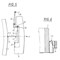
- the two couplers 5 and 6 can either by one direct attack on these can be adjusted or by adjusting screws 20 (see schematic diagram in Figure 5), which about a parallel guidance with a gear ratio on the Adjustment of the coupling 5 and 6 in the direction of the x or y axis (see arrows).
- the parallel guide shown only has one Transmission lever 21 on which the adjusting screw 20 engages.
- the translation lever 21 is articulated with a shoulder 22 one Angle lever 23 connected, which in turn with his other Leg as the drive leg 24 with an adjusting plate 25 Stellkoppel 5 or 6 is connected.
- the setting angle 23 is over an articulated connection 26 connected to the outer ring 8.
- the adjusting plate 25 is again on another leg 27 hinged to the outer ring 8.
- the setting angle 23, the Setting plate 25 and the leg 27 form a parallel guide for the joint 11 of the coupling 5 or 6.
- Figure 6 shows an enlarged section of section VI-VI 3 shows a structural design of the adjusting coupling 5 or 6 with solid-state joints 10, 11.
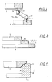
- FIGS. 7 to 9 show some configurations of support couplers, which, however, can only be seen as an example.
- the support coupling 1, 2, 3 or 4 shown in FIG. 7 is provided with low-friction ball joints 28 and 29, which the Form joints 10 and 11.
- FIG. 8 shows an embodiment of the support coupling 1 to 4 with Solid-state joints 10 and 11, as in the embodiment according to Figures 1 to 6 are shown by Formation of elastic, thin transition points between the one-piece inner ring 7 and outer ring 8.
- FIG. 9 shows a special type, the support coupling 1 to 4 by spherical surfaces between the inner ring 7 and the outer ring 8 are formed or assume their function. In doing so the joints 10 and 11 through the curved surfaces on the inner ring 7 and formed on the outer ring 8, with a radius of curvature smaller than the other radius of curvature.
- the kinematic pivot points 10 and 11 of this connection lie on the centers of curvature the spherical surfaces.
- the device each four support coupling 1 to 4, the starting points are evenly distributed around the circumference on the inner ring 7, and two adjusting brackets 5 and 6, which enclose an angle of 90 °.
- the optical element can be used a mirror or another optical element is also provided that is decoupled from deformation.
Abstract
Description
Die Erfindung betrifft eine Vorrichtung zum Kippen eines
Gegenstandes um wenigstens eine Achse, insbesondere eines
optischen Elementes, nach dem Oberbegriff von Anspruch 1.The invention relates to a device for tilting a
Object around at least one axis, in particular one
optical element, according to the preamble of
Eine Vorrichtung dieser Art ist in der DD 278 207 Al beschrieben. Dabei ist eine Fassung mit Justierelementen vorgesehen, auf denen einzeln gefaßte optische Elemente in einem Füllfassungsrohr angeordnet sind. Die Justierelemente bestehen aus zwei unmittelbar aneinandergrenzende, ineinander und unabhängig voneinander verdrehbare Ringscheiben. Durch Drehungen der Ringscheiben, welche ein Keilringpaar bilden, läßt sich eine definierte Neigung der optischen Achse des optischen Elementes einstellen. Auf diese Weise können die optischen Achsen einzelner optischer Elemente mit hoher Genauigkeit zur mechanischen Achse eines Objektives ausgerichtet werden. Mit einer Vorrichtung dieser Art wird erreicht, daß die optische Achse eines einzelnen optischen Elementes, das mit der optischen Achse des Objektives, in das das optische Element eingebaut ist, nicht übereinstimmt, ausgerichtet werden kann.A device of this type is in DD 278 207 Al described. There is a socket with adjustment elements provided on which individually composed optical elements in a filling tube are arranged. The adjustment elements consist of two directly adjacent, one inside the other and independently rotatable washers. By Rotations of the washers, which form a pair of wedge rings, a defined inclination of the optical axis of the adjust the optical element. That way they can optical axes of individual optical elements with high Accuracy to the mechanical axis of a lens be aligned. With a device of this type achieved that the optical axis of a single optical Element with the optical axis of the lens in the the optical element is installed, does not match, can be aligned.
Die Schiefstellung einer optischen Achse eines optischen Elementes kann z.B. durch Fertigungsungenauigkeiten oder Flanschunebenheiten eines Außenringes verursacht sein. Durch die Justierelemente nach der DD 278 207 A1 lassen sich Abweichungen der optischen Achsen von optischen Elementen von der Achse des Objektives, aber nicht in der für Objektive für die Halbleiterlithographie geforderten hohen Genauigkeit korrigieren, da die Justage mit dem Keilringpaar reibungsbehaftet ist und somit sogenannten Stick-Slip- und Hystereseeffekte auftreten, die ein "Über"korrigieren zur Folge haben. Es wird daher immer eine etwas größere Verstellung wie erwünscht eingestellt. Zudem wird bei der vorbekannten Vorrichtung das optische Element jedoch von der Außenfassung nicht deformationsentkoppelt, so daß Verspannungen und Deformationen am Flansch auf das optische Element übertragen werden.The skewing of an optical axis of an optical element can e.g. due to manufacturing inaccuracies or uneven flanges an outer ring. Through the adjustment elements according to DD 278 207 A1 there are deviations the optical axes of optical elements from the axis of the Objectives, but not for lenses for semiconductor lithography correct the required high accuracy because the Adjustment with the pair of wedge rings is fraught with friction and thus so-called stick-slip and hysteresis effects occur that a Correcting "About" will result. So it always becomes one slightly larger adjustment as desired. In addition, in the known device, however, the optical element not decoupled from the outer frame deformation, so that tension and deformations on the flange on the optical element be transmitted.
Der vorliegenden Erfindung liegt die Aufgabe zugrunde, eine Vorrichtung der eingangs erwähnten Art derart zu verbessern, daß ein Gegenstand, insbesondere ein optisches Element, sehr genau von wenigstens um eine Achse, insbesondere jedoch um zwei Achsen, geschwenkt werden kann, wobei der Gegenstand gleichzeitig auch gegenüber seiner Fassung oder seinem Außenring deformationsentkoppelt sein soll.The present invention has for its object a To improve the device of the type mentioned at the outset in such a way that an object, especially an optical element, very much exactly of at least around one axis, but especially around two Axes, can be pivoted, the object at the same time also decoupled from deformation in relation to its socket or its outer ring should be.
Erfindungsgemäß wird diese Aufgabe durch die im kennzeichnenden
Teil von Anspruch 1 genannten Merkmale gelöst.According to the invention, this task is characterized by
Part of
Erfindungsgemäß ist der Innenring, der das optische Element trägt, nunmehr über insgesamt sechs Koppeln mit der Fassung bzw. dem Außenring verbunden. Vier Koppeln dienen dabei als sogenannte Stützkoppeln derart, daß sich der Innenring nur um die beiden senkrecht zueinander stehenden Kippachsen drehen kann. Die beiden anderen Koppeln, die als Stellkoppeln wirken, stützen jeweils die Drehmomente um die beiden Kippachsen (x-Achse und y-Achse) ab und dienen gleichzeitig zur Einstellung und Verstellung der Kippwinkel. Durch die Koppeln ist die Lagerung des Innenringes somit statisch bestimmt, wobei gleichzeitig auf diese Weise eine Deformationsentkoppelung des Innenringes gegenüber dem Außenring erreicht wird. Da die beiden Kippachsen senkrecht zueinander stehen, beeinflussen sich die Kippbewegungen nicht gegenseitig, weshalb Nachkorrekturen bei Verstellung in einer Richtung nicht notwendig werden.According to the invention, the inner ring is the optical element now carries over a total of six coupling with the frame or the outer ring connected. Four paddocks serve as so-called support coupling in such a way that the inner ring only around rotate the two tilt axes perpendicular to each other can. The other two couplers, which act as adjusting couplers, support the torques around the two tilt axes (x-axis and y-axis) and are also used for adjustment and adjustment of the tilt angle. The coupling is the storage of the inner ring thus determined statically, at the same time in this way a deformation decoupling of the inner ring towards the outer ring. Because the two tilt axes standing perpendicular to each other, the tilting movements influence each other not mutually, which is why post-corrections when adjusting in one direction are not necessary.
Wenn in einer sehr vorteilhaften Ausgestaltung der Erfindung vorgesehen ist, daß die beiden Kippachsen durch die z-Achse, d.h. bei einem optischen Element als Gegenstand durch die optische Achse verlaufen, wird ein Höhenversatz des optischen Elementes beim Kippen vermieden. If in a very advantageous embodiment of the invention it is provided that the two tilt axes through the z axis, i.e. with an optical element as an object by the optical Axis, there will be a height offset of the optical element avoided when tipping.
Die Ausgestaltung der Stützkoppeln kann beliebig sein. So können hierfür z.B. Festkörpergelenke, Kugelgelenke oder ähnliches verwendet werden, wobei die Verbindung mit dem Innenring und dem Außenring jeweils über ein Gelenk bzw. eine einstellbare oder nachgiebige Verbindung erfolgen kann.The design of the support coupling can be any. So can for this e.g. Solid-state joints, ball joints or the like are used, the connection with the inner ring and the outer ring via a joint or an adjustable or compliant connection can be made.
Bei aus der Praxis bekannten Kippmanipulatoren, die auf einer Dreipunkt- oder Hexapodlagerung des Innenrings im Außenring basieren, erfährt beim Kippen das optische Element wegen der zur optischen Achse windschief liegenden Kippachsen einen Höhenversatz, der durch Nachkippen um andere Kippachsen wieder herausgestellt werden muß. Da bei der erfindungsgemäßen Vorrichtung die beiden Kippachsen die optische Achse des optischen Elementes schneiden können, tritt in diesem Fall kein Axialversatz beim Kippen auf.In tilting manipulators known from practice, which are based on a Three-point or hexapod bearing of the inner ring in the outer ring based, experiences the optical element when tilted because of a tilt offset with respect to the optical axis by tilting around other tilt axes again must be highlighted. Since in the device according to the invention the two tilt axes the optical axis of the optical In this case, there can be no axial misalignment when tilting up.
Bei bekannten Kippmanipulatoren, ausgenommen kardanischen Aufhängungen, beeinflussen sich weiterhin die Kippbewegungen gegenseitig, da die Kippachsen nicht senkrecht zueinander stehen. Bei der erfindungsgemäßen Vorrichtung hingegen stehen die Kippachsen senkrecht zueinander, so daß keine gegenseitige Beeinflussung der Kippbewegungen gegeben ist.In known tilt manipulators, except gimbal suspensions, the tilting movements continue to influence each other, because the tilt axes are not perpendicular to each other. In contrast, in the device according to the invention Tilt axes perpendicular to each other, so that no mutual The tilting movements are influenced.
Erfindungsgemäß ist der Verstellbereich so gewählt, daß der Kippwinkel zwischen Innenring und Außenring, der bei einer Außenringdeformation, z.B. durch Anschrauben des Außenrings auf eine unebene Unterlage, durch die statisch bestimmte Lagerung entsteht, korrigiert werden kann. Denkbar ist auch eine gezielte Verkippung des Innenringes, wobei aus Gründen der Praktikabilität, z.B. Festkörpergelenke, im allgemeinen Verkippungen sich auf kleinere Winkelbereiche beschränken würden.According to the adjustment range is selected so that the Tilt angle between the inner ring and outer ring, which at a Outer ring deformation, e.g. by screwing on the outer ring an uneven surface due to the statically determined storage arises, can be corrected. A targeted one is also conceivable Tilting of the inner ring, whereby for reasons of practicability, e.g. Solid-state joints, generally tilting would be limited to smaller angular ranges.
Weitere vorteilhafte Ausgestaltungen und Weiterbildungen ergeben sich aus den übrigen Unteransprüchen und aus dem nachfolgend anhand der Zeichnung prinzipmäßig dargestellten Ausführungsbeispiel. Further advantageous refinements and developments result from the remaining subclaims and from the shown in principle below with reference to the drawing Embodiment.
Es zeigt:
Figur 1- schematisch eine perspektivische Darstellung der erfindungsgemäßen Vorrichtung mit einem Innenring, Stütz- und Stellkoppeln und einem Außenring,
Figur 2- eine Draufsicht auf die Vorrichtung nach
Figur 1 in Prinzipdarstellung, Figur 3- eine Draufsicht auf die erfindungsgemäße Vorrichtung in einer konstruktiven Ausgestaltung,
Figur 4- einen Schnitt nach der Linie IV-IV der Fig. 3 in vergrößerter Darstellung,
Figur 5- ausschnittsweise eine Prinzipdarstellung einer Stellkoppel mit Verstelleinrichtung,
Figur 6- einen Schnitt nach der Linie VI-VI der Fig. 3 in vergrößerter Darstellung,
Figur 7- eine vergrößerte Darstellung einer Stützkoppel mit Kugelgelenken,
Figur 8- eine vergrößerte Darstellung einer Stützkoppel mit Festkörpergelenken, und
- Figur 9
- eine vergrößerte Darstellung einer Stützkoppel mit Kugelflächen.
- Figure 1
- schematically a perspective view of the device according to the invention with an inner ring, support and adjusting coupling and an outer ring,
- Figure 2
- 2 shows a top view of the device according to FIG. 1 in a basic illustration,
- Figure 3
- a plan view of the device according to the invention in a constructive embodiment,
- Figure 4
- 3 shows a section along the line IV-IV of FIG. 3 in an enlarged view,
- Figure 5
- excerpts a basic representation of an adjusting coupling with adjustment device,
- Figure 6
- 4 shows a section along the line VI-VI of FIG. 3 in an enlarged view,
- Figure 7
- an enlarged view of a support coupling with ball joints,
- Figure 8
- an enlarged view of a support coupling with solid joints, and
- Figure 9
- an enlarged view of a support coupling with spherical surfaces.
Vier Stützkoppeln 1, 2, 3 und 4 und zwei Stellkoppeln 5 und 6
verbinden einen Innenring 7 mit einem Außenring 8. Der Innenring
7 trägt ein optisches Element 9 (in der Figur 1 aus Übersichtlichkeitsgründen
nicht dargestellt). Jede der sechs Koppeln
besitzt ein Gelenk 10, mit welchem die dazugehörige Koppel
mit dem Innenring 7 und ein weiteres Gelenk 11, mit welchem
ebenfalls die dazugehörige Koppel mit dem Außenring 8 oder einen
Verstellmechanismus (siehe Figur 5, Bezugszeichen 21-27),
der vom Außenring 8 gehalten wird, verbunden ist. Die Gelenke
10 und 11 können als Kugelgelenke, Festkörpergelenke oder in
ähnlicher Weise ausgebildet sein.Four
Durch die Verbindung des Innenringes 7 mit dem Außenring 8 über
die sechs Koppeln ist der Innenring 7 von Fertigungsungenauigkeiten
des Außenringes 8 bzw. der Fassung und von dessen Deformationen
entkoppelt. Gleichzeitig kann über die sechs Koppeln
jedoch eine Justage um zwei senkrecht zueinander stehende Achsen,
nämlich die x-Achse und die y-Achse, vorgenommen werden.
Dies geschieht auf folgende Weise:By connecting the
Durch die vier Stützkoppeln 1, 2, 3 und 4 wird der Innenring 7
derart auf dem Außenring 8 getragen, daß für den Innenring 7
nur noch zwei Freiheitsgrade, nämlich um die x-Achse und die y-Achse,
gegeben sind. Diese beiden Achsen stellen die Kippachsen
dar. Die y-Achse als Dreh- bzw. Kippachse ergibt sich dabei
durch die Schnittpunkte 12 und 13, deren Verbindungslinie die
y-Achse darstellt. Der Schnittpunkt 12 ergibt sich hierfür aus
der Verlängerungslinie 14 der Stützkoppel 1 mit der Verlängerungslinie
15 der Stützkoppel 2 und der Schnittpunkt 13 ergibt
sich aus der Verlängerungslinie 16 der Stützkoppel 3 mit der
Verlängerungslinie 17 der Stützkoppel 4.The
In ähnlicher Weise wird die Dreh- bzw. Kippachse, welche 90°
dazu liegt, nämlich der x-Achse, mittels einer Verbindungslinie
durch die Schnittpunkte 18 und 19 gebildet. Der Schnittpunkt 18
ergibt sich dabei durch die Verlängerungslinie 15 der Stützkoppel
2 mit der Verlängerungslinie 16 der Stützkoppel 3. Der
Schnittpunkt 19 ergibt sich durch die Verlängerungslinie 14 der
Stützkoppel 1 mit der Verlängerungslinie 17 der Stützkoppel 4.
Anders ausgedrückt: Die Stützkoppeln 1 und 2 bilden im Ausführungsbeispiel
eine Ebene und die Stützkoppeln 3 und 4 bilden
die andere Ebene, wobei die Schnittgerade beider Ebenen die
Kippachse darstellt. Similarly, the axis of rotation or tilt, which is 90 °
lies to this, namely the x-axis, by means of a connecting line
formed by the
Bei dieser Ausgestaltung und Anordnung der Stützkoppeln 1 bis 4
gehen die Dreh- bzw. Kippachsen x-, y-Achse, genau durch die z-Achse.
Dabei liegt ein Anstellwinkel α als Stützkoppelanstellwinkel
der Winkel zwischen der Stützkoppel 1, 2, 3 oder 4 und
der xy-Ebene. Wie ersichtlich, sind die beiden Kippachsen gemäß
Ausführungsbeispiel nach der Fig. 1 jedoch in der Höhe versetzt
zueinander, weshalb sich bei einer Kippung ein Lateralversatz
einstellt. Je näher die beiden Kippachsen zum Innenring 7 liegen,
d.h. je flacher ein Anstellwinkel α der Stützkoppeln zur
xy-Ebene ist, desto geringer wird der Lateralversatz. Nachteilig
ist jedoch, daß dabei die Steifigkeit der Vorrichtung in z-Richtung
leidet. Umgekehrt, je steiler bzw. je größer die Winkel
a der Stützkoppeln zur z-Achse sind, desto weiter liegen
die Kippachsen vom Außenring 8 weg und desto steifer wird die
Vorrichtung in z-Richtung, wobei jedoch entsprechend der Lateralversatz
zunimmt. Dies bedeutet, in der Praxis wird man die
Anstellwinkel α der Stützkoppeln entsprechend den gewünschten
Anforderungen wählen.In this configuration and arrangement of the
Die Stellkoppel 5, welche auf der x-Achse vom Innenring 7 bzw.
Außenring 8 liegt, stützt Drehmomente um die y-Achse ab. Der
Kippwinkel des Innenringes 7 um die y-Drehachse kann durch ein
Verschieben der Stellkoppel 5 in x-Richtung gegenüber dem
Außenring 8 eingestellt werden.The adjusting
Die Stellkoppel 6 stützt die Drehmomente um die x-Achse ab und
befindet sich hierzu auf der y-Achse des Außenringes 8. Durch
ein Verschieben der Stellkoppel 6 in y-Richtung gegenüber dem
Außenring 8 kann der Kippwinkel des Innenringes 7 um die x-Achse
eingestellt werden.The adjusting
Ein Anordnungswinkel ϕ beschreibt die Anordnung der Stützkoppeln
1 bis 4 zum Innenring 7 in der Draufsicht (siehe Figur 2).
Der Anordnungswinkel ϕ ist der Winkel zwischen der Tangente des
Ansatzpunktes der Stützkoppel 1, 2, 3 bzw. 4 am Innenring 7 und
der in die xy-Ebene projizierte Stützkoppel. Der Anordnungswinkel
ϕ der Stützkoppel 1, 2, 3 bzw. 4 legt damit die axiale Lage
der Kippachsen zueinander fest. Da der Anstellwinkel α der
Stützkoppeln 1, 2, 3, 4 die Höhe der Kippachsen vom Außenring 8
bestimmt, teilt der Anordnungswinkel ϕ den Anstellwinkel α in
einen Anstellwinkel für die x-Kippachse, der die Projektion des
Anstellwinkels α auf die yz-Ebene ist, und in einen Anstellwinkel
für die Y-Kippachse, der die Projektion des Anstellwinkels
auf die zx-Ebene ist, auf.An arrangement angle ϕ describes the arrangement of the
Sind die Stützkoppeln 1, 2, 3, 4 radial zum Innenring ausgerichtet
(ϕ = 90°), so sind die projizierten Winkel gleich groß,
und damit liegen die x- und y-Kippachsen gleichweit vom Außenring
8 entfernt. Die x- und y-Kippachsen schneiden sich und
spannen dann eine horizontale Ebene auf. In diesem Fall liegt
auch für beide Kipprichtungen ein gleicher Lateralversatz vor.Are the
Die Stützkoppeln 1 bis 4 können von tangential (ϕ = 0°) bis zu
radial (ϕ = 90°) an den Innenring 7 angeordnet werden.The
Bei tangentialer Anordnung der Stützkoppeln 1 bis 4 liegt eine
Kippachse oberhalb des Außenringes 8, während die andere Kippachse
im gleichen Abstand unterhalb des Außenringes 8 liegt
(nicht dargestellt).In the case of a tangential arrangement of the
Dies bedeutet, die beiden Kippachsen, nämlich die x- und y-Achsen,
liegen auf diese Weise auf verschiedenen Seiten des
Innenringes 7 bzw. Außenringes 8. Der Vorteil dieser Ausgestaltung
liegt in einer platzsparenden Anordnung.This means the two tilt axes, namely the x and y axes,
are in this way on different sides of the
Je nach den Anforderungen an die Vorrichtung und den Platzverhältnissen sind im Bedarfsfalle sämtliche Anordnungswinkel ϕ zwischen radial und tangential möglich.Depending on the requirements for the device and the space available if necessary, all arrangement angles Bedarf possible between radial and tangential.
Bei der Wahl des Anordnungswinkels ϕ der Stützkoppel 1, 2, 3, 4
sollte berücksichtigt werden, daß nichtschneidende Kippachsen
unterschiedliche Lateralversätze in den beiden Kipprichtungen
bewirken. When choosing the arrangement angle ϕ of the
In den Figuren 2 bis 6 ist in der Draufsicht in Prinzipdarstellung
eine mögliche Ausgestaltung für die Stützkoppeln 1, 2, 3
und 4 und die Stellkoppeln 5 und 6 dargestellt. Wie ersichtlich,
liegen die Stützkoppeln 1, 2, 3, 4 stets auf Geraden von
45° zum Innenring. Wie weiterhin ersichtlich, sind die Stützkoppeln
1, 2, 3 und 4 jeweils über das Gelenk 11 mit dem Außenring
8 und das Gelenk 10 mit dem Innenring verbunden. Die Figur
4 zeigt einen Schnitt nach der Linie IV-IV der Figur 3 mit
einer Ausgestaltung der Stützkoppeln 1 bis 4 als Festkörpergelenke
in vergrößerter Darstellung. Dabei sind auch die Gelenkpunkte
10, 11 erkennbar.In Figures 2 to 6 is a top view in principle
a possible configuration for the
Die beiden Stellkoppeln 5 und 6 können entweder durch einen
direkten Angriff an diesen verstellt werden oder durch Stellschrauben
20 (siehe Prinzipdarstellung in Figur 5), welche über
eine Parallelführung mit einem Übersetzungsverhältnis auf die
Verstellung der Stellkoppeln 5 und 6 in Richtung der x- bzw. y-Achse
(siehe Pfeile) einwirken.The two
Die nur beispielsweise dargestellte Parallelführung weist einen
Übersetzungshebel 21 auf, an dem die Stellschraube 20 angreift.
Der Übersetzungshebel 21 ist gelenkig mit einem Ansatz 22 eines
Winkelhebels 23 verbunden, welcher wiederum mit seinem anderen
Schenkel als Antriebsschenkel 24 mit einer Stellplatte 25 der
Stellkoppel 5 bzw. 6 verbunden ist. Der Stellwinkel 23 ist über
eine gelenkige Verbindung 26 mit dem Außenring 8 verbunden.
Über einen weiteren Schenkel 27 ist die Stellplatte 25 nochmals
gelenkig mit dem Außenring 8 verbunden. Der Stellwinkel 23, die
Stellplatte 25 und der Schenkel 27 bilden eine Parallelführung
für das Gelenk 11 der Stellkoppel 5 bzw. 6. Wie ersichtlich,
führen Verstellbewegungen der Stellschraube 20 in Pfeilrichtung
zu einer Verschiebung der Stellkoppel 5 in x-Richtung und der
Stellkoppel 6 in y-Richtung. Auf diese Weise erhält man bei
einem großen Verstellweg mit der Stellschraube 20 eine sehr
feine Verschiebung bzw. Anstellung der Stellkoppeln 5 und 6 in
x- bzw. y-Richtung. The parallel guide shown only has one
Figur 6 zeigt als Ausschnittsvergrößerung des Schnittes VI-VI
der Figur 3 eine konstruktive Ausgestaltung der Stellkoppel 5
bzw. 6 mit Festkörpergelenken 10, 11.Figure 6 shows an enlarged section of section VI-
Die Figuren 7 bis 9 zeigen einige Ausgestaltungen von Stützkoppeln, welche jedoch nur als beispielsweise anzusehen sind.FIGS. 7 to 9 show some configurations of support couplers, which, however, can only be seen as an example.
Die in der Figur 7 dargestellte Stützkoppel 1, 2, 3 oder 4 ist
mit reibungsarmen Kugelgelenken 28 und 29 versehen, welche die
Gelenke 10 und 11 bilden.The
Die Figur 8 zeigt eine Ausführung der Stützkoppeln 1 bis 4 mit
Festkörpergelenken 10 und 11, wie sie in dem Ausführungsbeispiel
nach den Figuren 1 bis 6 dargestellt sind und zwar durch
Bildung von elastischen, dünnen Übergangsstellen zwischen dem
einstückig gefertigten Innenring 7 und Außenring 8.FIG. 8 shows an embodiment of the
Die Figur 9 zeigt eine Spezialart, wobei die Stützkoppeln 1 bis
4 durch Kugelflächen zwischen dem Innenring 7 und dem Außenring
8 gebildet werden bzw. deren Funktion übernehmen. Dabei werden
die Gelenke 10 und 11 durch die Krümmungsflächen am Innenring 7
und am Außenring 8 gebildet, wobei ein Krümmungsradius kleiner
ist als der andere Krümmungsradius. Die kinematischen Gelenkpunkte
10 und 11 dieser Verbindung liegen dabei auf den Krümmungsmittelpunkten
der Kugelflächen.FIG. 9 shows a special type, the
Bei den vorstehend beschriebenen Ausführungsbeispielen besitzt
die Vorrichtung jeweils vier Stützkoppeln 1 bis 4, deren Ansatzpunkte
am Innenring 7 gleichmäßig am Umfang verteilt sind,
und zwei Stellkoppeln 5 und 6, die einen Winkel von 90° einschließen.In the above-described embodiments
the device each four
Bei einer Ausführung der Stützkoppeln 1 bis 4 und der Stellkoppeln
5 und 6 mit Festkörpergelenken können für eine symmetrische
Deformation des Innenringes 7 durch die Festkörpergelenk-Biegemomente
zusätzlich Ausgleichskoppeln angebracht werden.
Derartige Ausgleichskoppeln können umfangseitig gegenüber den
Stellkoppeln 5 und 6 angeordnet werden, besitzen jedoch selbst
keine Stellfunktion. Selbstverständlich können die Ausgleichskoppeln
jedoch auch noch an einer anderen Stelle angeordnet
werden. Ersetzt man die Festkörpergelenke derartiger Ausgleichskoppeln
durch ideale Gelenke, müssen die Ausgleichskoppeln
am Innenring 7 alle sechs Freiheitsgrade freigeben.In the case of a
Obwohl vorstehend nur Vorrichtungen mit jeweils vier Stützkoppeln 1 bis 4 beschrieben sind, wird nachdrücklich darauf hingewiesen, daß auch im Rahmen der Erfindung andere Anzahlen, Anordnungen und Gestaltungen von Stützkoppeln möglich sind. So sind z.B. auch Einsatzfälle möglich, wobei nur zwei sich gegenüberliegende Stützkoppeln vorhanden sind, die jeweils um 90° versetzt zu Stellkoppeln, welche sich ebenfalls gegenüberliegen, angeordnet sind.Although above only devices with four support couplers each 1 to 4, it is emphasized that that other numbers, arrangements within the scope of the invention and designs of support couplers are possible. So are e.g. applications are also possible, with only two opposing ones Support couplers are available, each 90 ° offset to adjusting couplers, which are also opposite each other, are arranged.
Als optisches Element kann statt einer Linse 9 selbstverständlich auch ein Spiegel oder ein anderes optisches Element vorgesehen sein, das deformationsentkoppelt wird.Of course, instead of a lens 9, the optical element can be used a mirror or another optical element is also provided that is decoupled from deformation.
Claims (12)
Applications Claiming Priority (2)
| Application Number | Priority Date | Filing Date | Title |
|---|---|---|---|
| DE19905779 | 1999-02-12 | ||
| DE19905779A DE19905779A1 (en) | 1999-02-12 | 1999-02-12 | Device for tilting an object around at least one axis, in particular an optical element |
Publications (2)
| Publication Number | Publication Date |
|---|---|
| EP1028342A1 true EP1028342A1 (en) | 2000-08-16 |
| EP1028342B1 EP1028342B1 (en) | 2003-08-27 |
Family
ID=7897224
Family Applications (1)
| Application Number | Title | Priority Date | Filing Date |
|---|---|---|---|
| EP00102490A Expired - Lifetime EP1028342B1 (en) | 1999-02-12 | 2000-02-05 | Device for pivoting an optical element around two orthogonal axes |
Country Status (4)
| Country | Link |
|---|---|
| US (1) | US6271976B1 (en) |
| EP (1) | EP1028342B1 (en) |
| JP (1) | JP2000235134A (en) |
| DE (2) | DE19905779A1 (en) |
Cited By (2)
| Publication number | Priority date | Publication date | Assignee | Title |
|---|---|---|---|---|
| WO2002016993A1 (en) * | 2000-08-18 | 2002-02-28 | Nikon Corporation | Optical element holding device |
| JP2002162549A (en) * | 2000-08-18 | 2002-06-07 | Nikon Corp | Optical element holder, lens barrel and aligner, and method of manufacturing microdevice |
Families Citing this family (20)
| Publication number | Priority date | Publication date | Assignee | Title |
|---|---|---|---|---|
| DE19905779A1 (en) * | 1999-02-12 | 2000-08-17 | Zeiss Carl Fa | Device for tilting an object around at least one axis, in particular an optical element |
| JP4945845B2 (en) * | 2000-03-31 | 2012-06-06 | 株式会社ニコン | An optical element holding device, a lens barrel, an exposure apparatus, and a microdevice manufacturing method. |
| DE10039712A1 (en) * | 2000-08-14 | 2002-02-28 | Zeiss Carl | Device for adjusting the position of two components relative to one another |
| DE10051706A1 (en) * | 2000-10-18 | 2002-05-02 | Zeiss Carl | Device for supporting optical element, has approximately T-shaped joints with connection points between holders at outer ends of T-bearer and manipulators engaging T-support |
| DE10100546A1 (en) | 2001-01-08 | 2002-07-11 | Zeiss Carl | Device for adjusting an optical element in a lens |
| DE10106650B4 (en) * | 2001-02-12 | 2006-11-02 | Klaus Hoffmann | Binocular optical device, in particular electronic glasses, with an electronic camera for automatic focusing including correction of various vision defects |
| JP2002287023A (en) | 2001-03-27 | 2002-10-03 | Nikon Corp | Projection optical system, projection aligner equipped with projection optical system, and projection aligning method |
| TWI244119B (en) * | 2001-11-07 | 2005-11-21 | Asml Netherlands Bv | Lithographic apparatus and device manufacturing method |
| JP4134566B2 (en) * | 2002-02-04 | 2008-08-20 | 株式会社ニコン | Optical element positioning method and apparatus, projection optical system, and exposure apparatus |
| WO2004109357A1 (en) * | 2003-06-06 | 2004-12-16 | Nikon Corporation | Optical element holding device, lens barrel, exposing device, and device producing method |
| DE102004025832A1 (en) * | 2004-05-24 | 2005-12-22 | Carl Zeiss Smt Ag | Optics module for a lens |
| JP4654915B2 (en) * | 2003-12-25 | 2011-03-23 | 株式会社ニコン | Optical element holding device, lens barrel, exposure apparatus, and device manufacturing method |
| DE102004052154B4 (en) | 2004-10-24 | 2006-10-05 | Berliner Elektronenspeicherring-Gesellschaft für Synchrotronstrahlung mbH | Rotary bearing for the highly precisely adjustable angular position of an optical mirror |
| WO2007056595A1 (en) * | 2005-11-09 | 2007-05-18 | Thomson Licensing | Optical seaming adjuster |
| CN101652698B (en) * | 2007-02-28 | 2012-03-07 | 康宁股份有限公司 | Optical mount pivotable about a single point |
| FR2925963B1 (en) * | 2008-01-02 | 2010-08-13 | Briot Int | APPARATUS FOR PALPING AN OPTICAL GLASS MOUNT AND ASSOCIATED METHOD |
| WO2009110963A2 (en) * | 2008-02-29 | 2009-09-11 | Corning Incorporated | Kinematic optical mount |
| DE102009025309B4 (en) * | 2009-06-15 | 2016-12-22 | Toptica Photonics Ag | Kinematic holder |
| DE102013204305A1 (en) | 2013-03-13 | 2014-09-18 | Carl Zeiss Smt Gmbh | Arrangement for the actuation of at least one element in an optical system |
| DE102017203079A1 (en) * | 2017-02-24 | 2018-08-30 | Carl Zeiss Smt Gmbh | LITHOGRAPHIC APPARATUS AND METHOD |
Citations (4)
| Publication number | Priority date | Publication date | Assignee | Title |
|---|---|---|---|---|
| US3917385A (en) * | 1973-09-19 | 1975-11-04 | Rockwell International Corp | Simplified micropositioner |
| US3989358A (en) * | 1974-11-21 | 1976-11-02 | Kms Fusion, Inc. | Adjustable micrometer stage |
| US4298248A (en) * | 1980-05-16 | 1981-11-03 | The United States Of America As Represented By The Secretary Of The Navy | Pivotal support with independent adjusting elements and locking means |
| DD278207A1 (en) * | 1988-12-19 | 1990-04-25 | Zeiss Jena Veb Carl | ASSEMBLY WITH ADJUSTING ELEMENTS |
Family Cites Families (4)
| Publication number | Priority date | Publication date | Assignee | Title |
|---|---|---|---|---|
| US5353167A (en) * | 1992-07-22 | 1994-10-04 | The United States Of America As Represented By The United States Department Of Energy | Mirror mount |
| US5986827A (en) * | 1998-06-17 | 1999-11-16 | The Regents Of The University Of California | Precision tip-tilt-piston actuator that provides exact constraint |
| DE19901295A1 (en) * | 1999-01-15 | 2000-07-20 | Zeiss Carl Fa | Optical imaging device, in particular objective, with at least one optical element |
| DE19905779A1 (en) * | 1999-02-12 | 2000-08-17 | Zeiss Carl Fa | Device for tilting an object around at least one axis, in particular an optical element |
-
1999
- 1999-02-12 DE DE19905779A patent/DE19905779A1/en not_active Withdrawn
-
2000
- 2000-01-27 US US09/490,890 patent/US6271976B1/en not_active Expired - Lifetime
- 2000-02-05 DE DE50003407T patent/DE50003407D1/en not_active Expired - Fee Related
- 2000-02-05 EP EP00102490A patent/EP1028342B1/en not_active Expired - Lifetime
- 2000-02-07 JP JP2000028740A patent/JP2000235134A/en active Pending
Patent Citations (4)
| Publication number | Priority date | Publication date | Assignee | Title |
|---|---|---|---|---|
| US3917385A (en) * | 1973-09-19 | 1975-11-04 | Rockwell International Corp | Simplified micropositioner |
| US3989358A (en) * | 1974-11-21 | 1976-11-02 | Kms Fusion, Inc. | Adjustable micrometer stage |
| US4298248A (en) * | 1980-05-16 | 1981-11-03 | The United States Of America As Represented By The Secretary Of The Navy | Pivotal support with independent adjusting elements and locking means |
| DD278207A1 (en) * | 1988-12-19 | 1990-04-25 | Zeiss Jena Veb Carl | ASSEMBLY WITH ADJUSTING ELEMENTS |
Cited By (4)
| Publication number | Priority date | Publication date | Assignee | Title |
|---|---|---|---|---|
| WO2002016993A1 (en) * | 2000-08-18 | 2002-02-28 | Nikon Corporation | Optical element holding device |
| JP2002162549A (en) * | 2000-08-18 | 2002-06-07 | Nikon Corp | Optical element holder, lens barrel and aligner, and method of manufacturing microdevice |
| US7154684B2 (en) | 2000-08-18 | 2006-12-26 | Nikon Corporation | Optical element holding apparatus |
| US7420752B2 (en) | 2000-08-18 | 2008-09-02 | Nikon Corporation | Holding apparatus |
Also Published As
| Publication number | Publication date |
|---|---|
| DE50003407D1 (en) | 2003-10-02 |
| DE19905779A1 (en) | 2000-08-17 |
| US6271976B1 (en) | 2001-08-07 |
| EP1028342B1 (en) | 2003-08-27 |
| JP2000235134A (en) | 2000-08-29 |
Similar Documents
| Publication | Publication Date | Title |
|---|---|---|
| EP1028342B1 (en) | Device for pivoting an optical element around two orthogonal axes | |
| DE102009037135B4 (en) | Holding device for an optical element | |
| EP1749242A1 (en) | Optical module for a lens | |
| DE102006047666A1 (en) | Projection lens for micro lithography, has multiple lenses with local optical axis, where one lens is assigned to manipulator with actuators, and input force or input torque is attained by former actuators | |
| DE102009005954B4 (en) | damping device | |
| DE10344178B4 (en) | Holding and positioning device for an optical element | |
| EP1164397A1 (en) | Lens mount especially suited for semiconductor lithography projection lens | |
| WO2008022797A1 (en) | Projection exposure apparatus and optical system | |
| WO2010037778A1 (en) | Support elements for an optical element | |
| DE19901295A1 (en) | Optical imaging device, in particular objective, with at least one optical element | |
| DE102005057860A1 (en) | Lens, in particular projection objective for semiconductor lithography | |
| EP1015931A2 (en) | Optical system, especially a projection light facility for microlithography | |
| DE102016217479A1 (en) | OPTICAL MODULE WITH TILTABLE OPTICAL SURFACES | |
| DE10139805C1 (en) | Tension-free lens holder for UV objectives comprises supporting elements lying on the inner surface of a holding ring so that they can be moved by a pressing force directed radially | |
| EP1657577B1 (en) | Rotating bearing for high precision angular positioning of an object | |
| DE10116997A1 (en) | Scope | |
| EP0762081A1 (en) | Angular measurement device | |
| EP0431114A1 (en) | Fixed gantry mount for a precision coordinate-measuring instrument. | |
| DE102020134653B3 (en) | Adjustable optics holder for an optical element | |
| DE102018200181A1 (en) | Projection exposure machine with reduced parasitic deformation of components | |
| WO2003087944A2 (en) | Device for the low-deformation mounting of a rotationally asymmetric optical element | |
| DE102020205306A1 (en) | Assembly, especially in a microlithographic projection exposure system | |
| EP0425476A2 (en) | Device for relative shift | |
| DE102018209526A1 (en) | Projection exposure apparatus with an arrangement for holding optical elements with additional torsion decoupling | |
| DE102022115934B3 (en) | Screw gear drive as well as reticle stage and measuring device for semiconductor lithography applications |
Legal Events
| Date | Code | Title | Description |
|---|---|---|---|
| PUAI | Public reference made under article 153(3) epc to a published international application that has entered the european phase |
Free format text: ORIGINAL CODE: 0009012 |
|
| AK | Designated contracting states |
Kind code of ref document: A1 Designated state(s): DE FR NL |
|
| AX | Request for extension of the european patent |
Free format text: AL;LT;LV;MK;RO;SI |
|
| 17P | Request for examination filed |
Effective date: 20001114 |
|
| AKX | Designation fees paid |
Free format text: DE FR NL |
|
| 17Q | First examination report despatched |
Effective date: 20020617 |
|
| RIC1 | Information provided on ipc code assigned before grant |
Ipc: 7G 02B 7/00 A Ipc: 7G 02B 7/02 B Ipc: 7G 02B 7/182 B |
|
| RTI1 | Title (correction) |
Free format text: DEVICE FOR PIVOTING AN OPTICAL ELEMENT AROUND TWO ORTHOGONAL AXES |
|
| GRAH | Despatch of communication of intention to grant a patent |
Free format text: ORIGINAL CODE: EPIDOS IGRA |
|
| GRAS | Grant fee paid |
Free format text: ORIGINAL CODE: EPIDOSNIGR3 |
|
| GRAA | (expected) grant |
Free format text: ORIGINAL CODE: 0009210 |
|
| AK | Designated contracting states |
Designated state(s): DE FR NL |
|
| PG25 | Lapsed in a contracting state [announced via postgrant information from national office to epo] |
Ref country code: NL Free format text: LAPSE BECAUSE OF FAILURE TO SUBMIT A TRANSLATION OF THE DESCRIPTION OR TO PAY THE FEE WITHIN THE PRESCRIBED TIME-LIMIT Effective date: 20030827 Ref country code: FR Free format text: LAPSE BECAUSE OF FAILURE TO SUBMIT A TRANSLATION OF THE DESCRIPTION OR TO PAY THE FEE WITHIN THE PRESCRIBED TIME-LIMIT Effective date: 20030827 |
|
| REF | Corresponds to: |
Ref document number: 50003407 Country of ref document: DE Date of ref document: 20031002 Kind code of ref document: P |
|
| NLV1 | Nl: lapsed or annulled due to failure to fulfill the requirements of art. 29p and 29m of the patents act | ||
| PLBE | No opposition filed within time limit |
Free format text: ORIGINAL CODE: 0009261 |
|
| STAA | Information on the status of an ep patent application or granted ep patent |
Free format text: STATUS: NO OPPOSITION FILED WITHIN TIME LIMIT |
|
| 26N | No opposition filed |
Effective date: 20040528 |
|
| EN | Fr: translation not filed | ||
| PGFP | Annual fee paid to national office [announced via postgrant information from national office to epo] |
Ref country code: DE Payment date: 20080219 Year of fee payment: 9 |
|
| PG25 | Lapsed in a contracting state [announced via postgrant information from national office to epo] |
Ref country code: DE Free format text: LAPSE BECAUSE OF NON-PAYMENT OF DUE FEES Effective date: 20090901 |