EP1657577B1 - Rotating bearing for high precision angular positioning of an object - Google Patents
Rotating bearing for high precision angular positioning of an object Download PDFInfo
- Publication number
- EP1657577B1 EP1657577B1 EP05090292A EP05090292A EP1657577B1 EP 1657577 B1 EP1657577 B1 EP 1657577B1 EP 05090292 A EP05090292 A EP 05090292A EP 05090292 A EP05090292 A EP 05090292A EP 1657577 B1 EP1657577 B1 EP 1657577B1
- Authority
- EP
- European Patent Office
- Prior art keywords
- cage
- rotational
- bearing
- holding element
- bearing according
- Prior art date
- Legal status (The legal status is an assumption and is not a legal conclusion. Google has not performed a legal analysis and makes no representation as to the accuracy of the status listed.)
- Active
Links
- 230000009471 action Effects 0.000 claims abstract description 10
- 229910000831 Steel Inorganic materials 0.000 claims description 10
- 239000010959 steel Substances 0.000 claims description 10
- 239000000463 material Substances 0.000 claims description 8
- 239000004033 plastic Substances 0.000 claims description 4
- 229920003023 plastic Polymers 0.000 claims description 4
- 239000002131 composite material Substances 0.000 claims description 3
- 229910001092 metal group alloy Inorganic materials 0.000 claims description 2
- 238000006243 chemical reaction Methods 0.000 claims 1
- 239000007787 solid Substances 0.000 abstract description 20
- 238000003860 storage Methods 0.000 description 34
- 230000033001 locomotion Effects 0.000 description 20
- 230000008878 coupling Effects 0.000 description 16
- 238000010168 coupling process Methods 0.000 description 16
- 238000005859 coupling reaction Methods 0.000 description 16
- 230000003287 optical effect Effects 0.000 description 11
- 238000005452 bending Methods 0.000 description 9
- 238000013461 design Methods 0.000 description 7
- 230000007246 mechanism Effects 0.000 description 5
- 238000013519 translation Methods 0.000 description 4
- 230000014616 translation Effects 0.000 description 4
- 230000008859 change Effects 0.000 description 3
- 239000000835 fiber Substances 0.000 description 3
- 238000004519 manufacturing process Methods 0.000 description 3
- 230000006978 adaptation Effects 0.000 description 2
- 229910052782 aluminium Inorganic materials 0.000 description 2
- XAGFODPZIPBFFR-UHFFFAOYSA-N aluminium Chemical compound [Al] XAGFODPZIPBFFR-UHFFFAOYSA-N 0.000 description 2
- 230000015572 biosynthetic process Effects 0.000 description 2
- 238000010276 construction Methods 0.000 description 2
- 229910052751 metal Inorganic materials 0.000 description 2
- 239000002184 metal Substances 0.000 description 2
- 238000005096 rolling process Methods 0.000 description 2
- 229910001220 stainless steel Inorganic materials 0.000 description 2
- 238000012549 training Methods 0.000 description 2
- 230000007704 transition Effects 0.000 description 2
- 238000003466 welding Methods 0.000 description 2
- 229910000906 Bronze Inorganic materials 0.000 description 1
- 229920000049 Carbon (fiber) Polymers 0.000 description 1
- RTAQQCXQSZGOHL-UHFFFAOYSA-N Titanium Chemical compound [Ti] RTAQQCXQSZGOHL-UHFFFAOYSA-N 0.000 description 1
- 239000000853 adhesive Substances 0.000 description 1
- 238000004026 adhesive bonding Methods 0.000 description 1
- 230000001070 adhesive effect Effects 0.000 description 1
- 230000008901 benefit Effects 0.000 description 1
- 229910052790 beryllium Inorganic materials 0.000 description 1
- ATBAMAFKBVZNFJ-UHFFFAOYSA-N beryllium atom Chemical compound [Be] ATBAMAFKBVZNFJ-UHFFFAOYSA-N 0.000 description 1
- 230000005540 biological transmission Effects 0.000 description 1
- 239000010974 bronze Substances 0.000 description 1
- 239000004917 carbon fiber Substances 0.000 description 1
- KUNSUQLRTQLHQQ-UHFFFAOYSA-N copper tin Chemical compound [Cu].[Sn] KUNSUQLRTQLHQQ-UHFFFAOYSA-N 0.000 description 1
- 238000005520 cutting process Methods 0.000 description 1
- 230000001419 dependent effect Effects 0.000 description 1
- 238000011161 development Methods 0.000 description 1
- 230000018109 developmental process Effects 0.000 description 1
- 238000006073 displacement reaction Methods 0.000 description 1
- 238000005553 drilling Methods 0.000 description 1
- 230000000694 effects Effects 0.000 description 1
- 230000007613 environmental effect Effects 0.000 description 1
- 239000004744 fabric Substances 0.000 description 1
- 230000002349 favourable effect Effects 0.000 description 1
- 230000006872 improvement Effects 0.000 description 1
- 238000005304 joining Methods 0.000 description 1
- 238000000034 method Methods 0.000 description 1
- NJPPVKZQTLUDBO-UHFFFAOYSA-N novaluron Chemical compound C1=C(Cl)C(OC(F)(F)C(OC(F)(F)F)F)=CC=C1NC(=O)NC(=O)C1=C(F)C=CC=C1F NJPPVKZQTLUDBO-UHFFFAOYSA-N 0.000 description 1
- 238000005457 optimization Methods 0.000 description 1
- 230000003071 parasitic effect Effects 0.000 description 1
- 239000002985 plastic film Substances 0.000 description 1
- 229920006255 plastic film Polymers 0.000 description 1
- 230000008569 process Effects 0.000 description 1
- 230000001681 protective effect Effects 0.000 description 1
- 230000003068 static effect Effects 0.000 description 1
- 239000010936 titanium Substances 0.000 description 1
- 229910052719 titanium Inorganic materials 0.000 description 1
Images


Classifications
-
- G—PHYSICS
- G02—OPTICS
- G02B—OPTICAL ELEMENTS, SYSTEMS OR APPARATUS
- G02B7/00—Mountings, adjusting means, or light-tight connections, for optical elements
- G02B7/18—Mountings, adjusting means, or light-tight connections, for optical elements for prisms; for mirrors
- G02B7/182—Mountings, adjusting means, or light-tight connections, for optical elements for prisms; for mirrors for mirrors
- G02B7/1822—Mountings, adjusting means, or light-tight connections, for optical elements for prisms; for mirrors for mirrors comprising means for aligning the optical axis
- G02B7/1827—Motorised alignment
Definitions
- the invention relates to a rotary bearing for highly accurately adjustable angular position of an object with a holding element for holding the object and a stationary base element, which is firmly connected to a plurality of circumferentially evenly distributed, each at both ends solid joints as elastically deformable deformation zones having oblique support coupling with the holding element is, and with an actuator for adjusting the angular position.
- a parallel kinematic guide for example Hexapode or Cartesian six-bar bearing, makes it possible to guide and adjust independent movements in all six Cartesian spatial directions.
- many applications do not require three translational and three rotational movements of the article.
- the three rotational degrees of freedom for the three Cartesian axes lying orthogonally to the mirror surface are generally sufficient. Often only the two become Tilting in the plane of the mirror needed, the rotation about the vertical axis can be omitted if it makes no adjustment changes for the beam path. However, rotation is of interest if the reflection is dependent on the surface structure of the mirror. Important for the adjustment of the angular position of a mirror is its rotation about its reflection pole. This is the optical center in the mirror surface, that is the part of the surface that reflects the center ray of the light. In special cases, such as in an autocorrelator, this point may also lie on the edge of the mirror surface.
- a rotation about the reflection pole is required so that no translational components occur and the mirror is not moved out of the incident light beam during the rotation.
- this point may be referred to as a "rotation pole” or “center of rotation” and may be specified at any desired location.
- the selected term "reflection pole” is to be transmitted in an analogous manner to the "rotation pole” in the case of non-reflecting objects.
- the functions as well as the sequential structure are similar to the aforementioned device, but on a larger scale. Both devices allow only two tilts of the mirror, a rotation around the Mirror standards can not be executed.
- the bars are not train push rods here, but torsion connections. They lie in the same or in parallel planes and do not exactly define the translational position of the mirror surface along its mirror normal.
- rotary bearing which is primarily intended to effect a deformation decoupling of the object from its socket, consists of an inner ring as a holding element for holding the object and an outer ring as a stationary base element. Between the inner ring and the outer ring four uniformly distributed around the circumference support coupling are arranged. These are connected via solid joints at each end firmly with the rings.
- the support coupling do not have a common point of intersection in their lines of action, but define the two possible tilt axes for the object, with the position of the intersection of the two tilt axes can quite a lateral offset when tilting occur.
- the orientation of the support coupling from radial to tangential thus determines the position of the tilt axes.
- the removal of the tilt axes from the reflection pole and the inner ring determines the rigidity of the device.
- On each of the two axes between the inner and outer ring is still a sliding actuator coupling arranged as an actuator for adjusting the angular positioning, which in each case supports the torque about the other axis.
- a high-precision rotation is not feasible even in this known device.
- a lateral offset in the tilting can only be prevented if the support coupling are radially aligned. In this positioning, however, the rigidity of the device is very low. However, this is for the high-precision positioning of particular importance and only increases when the support coupling are arranged obliquely, which in turn, however, a greater lateral displacement occurs.
- the solid-state joints are parallel in their lines of action and therefore do not allow exclusive rotation of a mirror in its reflection pole. From the basic task forth, this known arrangement is to align exactly two mirrors to each other. From the US 5,626,312 a similar arrangement is known, but which serves only the rotation of two elements to each other. From the DE 197 42 205 A1 For example, a high stiffness micropositioning device is known that allows for two translations and rotation through an array of alternating passive and active rods and solid joints between the support member and the socket member. The active rods (actuators) have different points of intersection for generating the movements. This ensures that with the same translation of both points of intersection purely translatory positioning movements are performed.
- the bending mechanism also includes a support member and a pedestal member between which inclined support pads are uniformly distributed on the circular periphery so as to intersect at a common convergence point above the support member.
- the flexible support coupling may for example consist of stainless steel wire and may be connected by ball and cylinder joints with the support member and the base member.
- the solution for this task according to the invention is that the holding element, the solid joints, the support coupling and the base element form a translationally stiff, common storage basket, wherein the support coupling formed as a spoke-like basket struts with high axial bending stiffness and adjacent three-dimensional star-shaped and are the lines of action Cut all basket struts in the stationary Rotationspol the object.
- the rotary bearing according to the invention essentially comprises a basket of a plurality of basket struts, which are all aligned at one point, the reflection point of the object to be positioned. It allows exactly three rotations about the Cartesian axes in the pole of reflection, but - apart from very small, predictable and reproducible so-called "parasitic shifts" - does not permit translation - not even vertically. This ensures that the object to be twisted does not leave its center of reflection and thus, for example, an optical beam path or changes the path length of a beam path.
- the structure of the claimed rotation bearing is very compact.
- the essential elements, retaining element, base element and support coupling, are basically fabric or positively connected with each other. Mistakes because there are no frictional rotatable joints.
- the rotations are done without play, friction and hysteresis exclusively on the solid joints. As a result, the reproducibility of the movements is extremely high.
- the axial or translational stiffness of the rotary bearing is also very high and highly static parallel, the space requirement and the mass are very low, the production cost is also very low.
- the solid-state hinges at both ends of the basket struts act as elastically deformable deformation zones that allow for three-axis applications bends in two orthogonal directions and rotation (ball-and-socket joints for meridional, sagittal, and azimuth rotations).
- An essential feature of the rotary bearing according to the invention is the bearing basket free of relative movements, which nevertheless allows a slight and at the same time very compact bearing design with the highest translational rigidity.
- the lines of action of the rods are predominantly not in one or in parallel planes.
- the storage basket may have different shapes, an adaptation to the particular application and the expression of the object to be stored is possible.
- the production is relatively simple, since no high accuracy limits must be met. It is advantageous if the storage basket is round or rectangular.
- the rotary bearing according to the invention is reminiscent of a shuttlecock in its appearance with its usually close to the circumference distributed basket struts. All basket straps point to the rotation or reflection pole of the object.
- gaps between the basket struts may be provided.
- a round training shows the greatest symmetry and thus homogeneous load capacity.
- Such a symmetrical design is particularly well suited for carrying symmetrical objects, for example a round mirror.
- it is easier to produce a rectangular design. Even with such training can without another alignment of all basket struts on the rotation point of the object done.
- a rectangular formation of the storage basket is suitable for storing rectangular objects, for example an elongate mirror block.
- the storage basket made of a metal alloy, a fiber composite material or a plastic.
- UHV ultrahigh vacuum
- aluminum, titanium, beryllium bronze or various stainless steels are suitable.
- the fiber composite materials, in particular with carbon fibers, and also plastics are well suited for this application, if the environmental conditions and other application parameters, such as weight of the object to be stored, allow this.
- there is also another way of producing the storage basket In addition to the conventional assembly of several items, it may for example also be integrally formed.
- the contour can be cut out of a metal sheet or a rigid plastic film by laser and then transferred into the spatial form.
- the joint can be closed by welding or gluing or remain open depending on the rigidity of the material selected.
- the storage basket can also be milled or eroded directly, for example from a corresponding aluminum blank. Relatively simple is the structure of the storage basket, if this is at least partially formed in one piece and the solid joints of constrictions are formed in the basket struts.
- a round storage basket can be bent together in one piece or a rectangular storage basket, for example, composed of two long and two short sides.
- the basket struts When working out the storage basket or sides thereof, it is advisable to constrict directly during the cutting process the basket struts in their connection to the holding or the base element, in their cross-section or only in their width, so that results in a lower bending strength and flexible solid-state bearing, the but still have sufficient rigidity to be formed.
- the basket struts of steel cables may be formed, which are each connected as a solid state joints with the holding element and the base member and have in their central region a rigid tube sleeve as a support coupling.
- the solid joints can thus be constructed of steel cable segments. These are crimped in tube sleeves, which then act as rods.
- the steel cable segments can be glued or clamped in the holding and the base element.
- Steel cable segments have the advantage that they damp vibrations well. Furthermore, they show greater elastic deformability than monolithic materials and are also very useful in the UHV range. The service life of steel cable segments is higher than that of monolithic material and a fatigue failure is due to the fraying, ie breaking of individual fibers on time. Spiral springs are in their properties between monolithic material and steel cable segments, are easily available commercially and easy to process.
- the adjustment of the rotary bearing according to the invention can be done in the context of the actuator via appropriate control elements by hand or by motor. Magnetic or electrostatic direct drives of the holding element are also conceivable.
- the mechanical drives are arranged so that for each rotational movement, a drive is provided which acts on a lever arm (boom).
- the lever arms are preferably arranged orthogonally so that a favorable decoupling of the individual rotation axes takes place.
- a remote control of the mechanical control elements via cable is possible. Basically, two concepts can be distinguished.
- a third actuator can attack Azimutalwindung of the article to a fixedly connected to the holding element boom.
- the central rod can be fixedly connected to the retaining element via a multiple leg which rises to the edge of the retaining element.
- the drive for the two tilting movements takes place from the interior of the storage basket, resulting in a very compact construction.
- the central rod is deflected by two actuating elements and transmits this deflection via its bearing on the holding element of the rotary bearing. This is tilted accordingly, the storage basket is deformed accordingly.
- the possible deflections are in the millimeter range. If the azimuth rotation is dispensed with, the boom is eliminated, so that the drive for the two tilting movements can only take place via the basket interior.
- a suitable arm can, for example, have a T-shape and be firmly connected centrally to the retaining element. Due to the generated high torques, a high-precision adjustment of all three rotations with this embodiment is particularly easy. Also in this embodiment, a cantilever can be omitted if an azimuth rotation is not required. In order to reliably prevent this, a bellows can be arranged congruent with the vertical axis of the storage basket in its interior to avoid the vertical rotation of the storage basket.
- the actuator for rotation about the azimuth then deleted accordingly.
- the bellows prevents rotation about the central axis, but he allows the two tilting movements without further ado.
- the bellows results in a further increase in the stiffness of the Rotation bearing and thus a further improvement of the setting accuracy in the micrometer range.
- a further increase in rigidity can also be achieved by arranging a plurality of identically shaped bearing baskets one above the other, with lines of action of all basket struts intersecting in the stationary rotation pole of the object. Due to the high degree of parallelism very high stiffness and thus positioning accuracies can be achieved. Due to the basket-like design of the storage basket is a nesting of a plurality of identically shaped storage baskets, which may have any shape, for example, round or square, without further possible. A connection of the individual storage baskets with each other must not take place, these can only be fastened together on the holding or on the base element. Further details on this embodiment and also on the abovementioned, to which the invention is not limited, can be found in the following specific description part. The same applies to the continuous representation of the basket struts as double joint bars, each with a solid-state joint at their ends. Also possible are embodiments in which the basket struts have further solid joints over their course in order to produce additional flexibility can.
- the high translational stiffness of the rotary bearing according to the invention allows to continue to increase the adjustment accuracy by means of differential spring gears.
- a spring is set between the actuator and the boom, which converts the path change of the actuator into a force change. Due to the stiffness of the spring, the force change per unit travel and thus the transmission ratio of the differential spring gear can be adjusted. Since in most applications high natural frequencies of the setup are sought, the high-level parallelism causes a very high Stiffness, which is very sensitively equipped by soft springs and with nevertheless very high dynamic position stability.
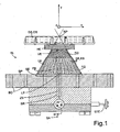
- the FIG. 1 shows a rotary bearing RL for highly accurate adjustable angular positioning of an object GS, in the embodiment of an optical mirror OS.
- This can be rotated by the rotary bearing RL around all three Cartesian axes x, y and z with angular adjustments in the ⁇ rad or nrad range.
- the two rotations about the x- and the z-axis are called "tilting" and the rotation about the y- axis is called azimuth rotation.
- the central element of the rotary bearing RL is a bearing basket LK, which is designed in the manner of a shuttlecock. At its lower edge, the bearing basket LK on a stationary base member SE , which formed in the embodiment shown as a round steel plate SP is.
- the bearing basket LK on a holding element HE , which serves to support the mirror OS .
- the holding element is for this purpose connected to a holding crown HK , which receives the mirror OS evenly.
- the storage basket LK has in its middle part a plurality of adjacent to its periphery adjacent oblique support coupling SK , which are formed as a spoke-like basket struts KS .
- the intersection is the origin of a Cartesian motion coordinate system.
- the storage basket LK is made in one piece.
- the holding element HE, the basket struts KS and the base element SE have been cut out, for example by laser from a metal sheet.
- the basket struts KS are designed rod-like and the solid state joints FG are formed by corresponding constrictions ES .
- the rotary bearing RL has a bellows FB which prevents vertical rotation of the rotary bearing RL . This should therefore only allow tilting in the embodiment shown.
- the bellows FB is connected at its upper end via connecting elements VE fixed to the holding element HE .
- a third actuator STE for bringing about an azimuth rotation of the mirror OS is not provided in the illustrated embodiment, but could easily be positioned on a corresponding boom AL .
- the central rod ZS is surrounded by a protective tube SR , resulting in a very compact and easy to handle rotary bearing RL .
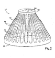
- FIG. 2 is the storage basket LK according to FIG. 1 shown in perspective.
- the holding element HE can be seen.
- this is a plate with holes BO for direct attachment of the object GS or indirect attachment of the article GS of other fasteners.
- the particularly compact design of the LK storage basket is easy to recognize. Its rigidity is very high, the space requirement and the mass are very low. The rotational movements take place without play, friction and hysteresis with a very high reproducibility.
- an actuator SA which has two actuating elements SE , which act on a central rod ZS .
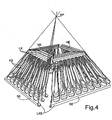
- an actuator SA is shown, which is realized by means of three arms AL .
- the three arms AL are integrally united in a T-shaped component TB , which is fixedly connected in its center on the bottom with the holding element HE and carries on the top of the object to be adjusted GS fixed.
- At each boom AL engages in each case an actuating element STE .
- the attack directions are chosen so that each a rotation in the x, y and z direction is effected. Good to recognize in FIG.
- a tilt in the x direction results when that in the FIG. 3 shown middle control element STE is moved vertically as an axial drive, the other two control elements STE remain fixed.
- Tilting in the z- direction results from the adjustment of the left-hand control element STE as an axial drive, which is arranged parallel to the central control element STE , with a fixation of the other two control elements STE.
- a pure rotation is effected by adjusting the right control element STE as an axial drive, which is arranged orthogonal to the two other control elements STE while they are fixed.
- any combination of individual movements can be brought about, so that each angular position of the object GS can be adjusted in the room with high accuracy.
- the shape of the storage basket LK is freely selectable and can be adapted to the respective application.
- FIG. 4 is a rectangular bearing basket LK shown, in which each bearing cage side LKS is made in one piece, for example, a very rigid plastic plate.
- the individual bearing cage sides LKS can, but need not be connected to each other.
- the base and retaining elements SE, HE corresponding to other connecting elements are firmly joined together.
- a highly parallel solution of particularly high stiffness results from the parallel connection of several storage baskets LK, as in US Pat FIG. 3 shown.
- the basket struts KS should not lie in a common or in parallel planes.
- each rotary bearing RL has a rectangular bearing basket LK and carries a rectangular optical mirror OS. At each rotary bearing RL all three rotations can be adjusted via control elements STE . In each case, two control elements STE on a boom AL and in each case an actuating element STE on a central rod ZS attack.
- the rotary bearings RL can be arranged both with the storage basket LK downwards and upwards, since the mirror OS is firmly connected to the holding element HE .
Landscapes
- Physics & Mathematics (AREA)
- General Physics & Mathematics (AREA)
- Optics & Photonics (AREA)
- Pivots And Pivotal Connections (AREA)
- Rolling Contact Bearings (AREA)
- Mounting And Adjusting Of Optical Elements (AREA)
- Support Of The Bearing (AREA)
- Magnetic Bearings And Hydrostatic Bearings (AREA)
- Sliding-Contact Bearings (AREA)
- Telescopes (AREA)
Abstract
Description
Die Erfindung bezieht sich auf ein Rotationslager zur hochgenau einstellbaren Winkelposition eines Gegenstandes mit einem Halteelement zur Halterung des Gegenstandes und einem ortfesten Sockelelement, das über mehrere am Umfang gleichmäßig verteilte, jeweils an beiden Enden Festkörpergelenke als elastisch deformierbare Verformungszonen aufweisende schräge Stützkoppeln mit dem Halteelement fest verbunden ist, und mit einem Stellantrieb zur Einstellung der Winkelposition.The invention relates to a rotary bearing for highly accurately adjustable angular position of an object with a holding element for holding the object and a stationary base element, which is firmly connected to a plurality of circumferentially evenly distributed, each at both ends solid joints as elastically deformable deformation zones having oblique support coupling with the holding element is, and with an actuator for adjusting the angular position.
Für Positionieraufgaben im Genauigkeitsbereich unterhalb eines Mikrometers scheiden Konstruktionen aus, die auf Wälz- oder Gleitlagern beruhen, oder auf kinematischen Aufstellungen, wie Kugel auf einer Planfläche, einem Konus, einer oder drei V-Nuten, kardanischen Gelenken oder gestapelten Einzelachsführungen, basieren. Die Formfehler der abwälzenden und gleitenden Körper und die Bewegungswiderstände durch Reibung führen zu unvermeidlichen Stellabweichungen oberhalb der einzuhaltenden Genauigkeit. Eine parallelkinematische Führung, beispielsweise Hexapode oder kartesisches Sechsstablager, ermöglicht es, in allen sechs kartesischen Raumrichtungen unabhängige Bewegungen zu führen und zu justieren. Für viele Anwendungen sind jedoch nicht drei translatorische und drei rotatorische Bewegungen des Gegenstandes erforderlich. Für die hochgenaue Winkelpositionierung eines optischen Spiegels in einem Strahlengang beispielsweise reichen die drei rotatorischen Freiheitsgrade für die orthogonal zur Spiegeloberfläche liegenden drei kartesischen Achsen in der Regel aus. Oft werden auch nur die zwei Kippungen in der Ebene des Spiegels benötigt, das Drehen um die vertikale Achse kann entfallen, wenn sie keine Einstellungsveränderungen für den Strahlengang erbringt. Das Drehen ist jedoch dann von Interesse, wenn die Reflexion von der Oberflächenstruktur des Spiegels abhängig ist. Wichtig für die Einstellung der Winkelposition eines Spiegels ist dessen Drehung um seinen Reflexionspol. Hierbei handelt es sich um den optischen Mittelpunkt in der Spiegeloberfläche, also den Teil der Oberfläche, der den Mittelstrahl des Lichtes reflektiert. In speziellen Fällen, wie z.B. in einem Autokorrelator, kann dieser Punkt auch am Rand der Spiegeloberfläche liegen. Eine Drehung um den Reflexionspol ist erforderlich, damit keine translatorischen Anteile auftreten und der Spiegel bei der Drehung nicht aus dem einfallenden Lichtstrahl herausgefahren wird. Bei nicht spiegelnden Oberflächen kann dieser Punkt als "Rotationspol" oder "Drehzentrum" bezeichnet werden, wobei er auch an einer beliebigen Sollstelle festgelegt werden kann. In den nachfolgenden Ausführungen ist daher der gewählte Begriff "Reflexionspol" in analoger Weise auf den "Rotationspol" bei nicht spiegelnden Gegenständen zu übertragen.For sub-micron precision positioning applications, designs based on rolling or plain bearings or based on kinematic setups such as a ball on a flat surface, a cone, one or three V-grooves, cardan joints or stacked single-axis guides are excluded. The shape errors of the rolling and sliding body and the resistance to movement caused by friction lead to unavoidable deviations above the accuracy to be maintained. A parallel kinematic guide, for example Hexapode or Cartesian six-bar bearing, makes it possible to guide and adjust independent movements in all six Cartesian spatial directions. However, many applications do not require three translational and three rotational movements of the article. For the high-precision angular positioning of an optical mirror in a beam path, for example, the three rotational degrees of freedom for the three Cartesian axes lying orthogonally to the mirror surface are generally sufficient. Often only the two become Tilting in the plane of the mirror needed, the rotation about the vertical axis can be omitted if it makes no adjustment changes for the beam path. However, rotation is of interest if the reflection is dependent on the surface structure of the mirror. Important for the adjustment of the angular position of a mirror is its rotation about its reflection pole. This is the optical center in the mirror surface, that is the part of the surface that reflects the center ray of the light. In special cases, such as in an autocorrelator, this point may also lie on the edge of the mirror surface. A rotation about the reflection pole is required so that no translational components occur and the mirror is not moved out of the incident light beam during the rotation. For non-reflecting surfaces, this point may be referred to as a "rotation pole" or "center of rotation" and may be specified at any desired location. In the following explanations, therefore, the selected term "reflection pole" is to be transmitted in an analogous manner to the "rotation pole" in the case of non-reflecting objects.
Aus der
Aus der
Aus der
Ferner ist aus der
Ausgehend von der weiter oben gewürdigten
Das erfindungsgemäße Rotationslager weist im Wesentlichen einen Korb aus einer Vielzahl von Korbstreben auf, die alle auf einen Punkt, den Reflexionspunkt des zu positionierenden Gegenstandes, ausgerichtet sind. Es erlaubt genau drei Rotationen um die kartesischen Achsen im Reflexionspol, lässt aber - abgesehen von sehr geringen, berechenbaren und reproduzierbaren so genannten "Parasitärverschiebungen" - keine Translation - auch nicht vertikal - zu. Somit ist gewährleistet, dass der zu verdrehende Gegenstand nicht seinen Reflexionsmittelpunkt und damit beispielsweise einen optischen Strahlengang verlässt oder die Weglänge eines Strahlenganges verändert. Der Aufbau des beanspruchten Rotationslagers ist sehr kompakt. Die wesentlichen Elemente, Halteelement, Sockelelement und Stützkoppeln, sind grundsätzlich stoff- oder kraftschlüssig miteinander verbunden. Fehler, da reibungsbehaftete drehbare Gelenke treten nicht auf. Die Drehungen erfolgen ohne Spiel, Reibung und Hysterese ausschließlich über die Festkörpergelenke. Dadurch ist die Reproduziergenauigkeit der Bewegungen extrem hoch. Die axiale bzw. translatorische Steifigkeit des Rotationslagers ist ebenfalls sehr hoch und hochgradig statisch parallel, der Platzbedarf und die Masse sind sehr gering, der Herstellungsaufwand ist ebenfalls sehr gering. Die Festkörpergelenke an beiden Enden der Korbstreben wirken als elastisch deformierbare Verformungszonen, die für dreiachsige Anwendungen Biegungen (Kippungen) in zwei orthogonalen Richtungen und Drehung zulassen (elastische Kugelgelenke für Meridional-, Sagittal- und Azimutaldrehungen).The rotary bearing according to the invention essentially comprises a basket of a plurality of basket struts, which are all aligned at one point, the reflection point of the object to be positioned. It allows exactly three rotations about the Cartesian axes in the pole of reflection, but - apart from very small, predictable and reproducible so-called "parasitic shifts" - does not permit translation - not even vertically. This ensures that the object to be twisted does not leave its center of reflection and thus, for example, an optical beam path or changes the path length of a beam path. The structure of the claimed rotation bearing is very compact. The essential elements, retaining element, base element and support coupling, are basically fabric or positively connected with each other. Mistakes because there are no frictional rotatable joints. The rotations are done without play, friction and hysteresis exclusively on the solid joints. As a result, the reproducibility of the movements is extremely high. The axial or translational stiffness of the rotary bearing is also very high and highly static parallel, the space requirement and the mass are very low, the production cost is also very low. The solid-state hinges at both ends of the basket struts act as elastically deformable deformation zones that allow for three-axis applications bends in two orthogonal directions and rotation (ball-and-socket joints for meridional, sagittal, and azimuth rotations).
Wesentliches Merkmal des Rotationslagers nach der Erfindung ist der von Relativbewegungen freie Lagerkorb, der bei höchster translatorischer Steifigkeit trotzdem einen leichte und dabei sehr kompakte Lagerbauart ermöglicht. Die Wirkungslinien der Stäbe liegen vorwiegend nicht in einer oder in parallelen Ebenen. Dabei kann der Lagerkorb unterschiedliche Formen aufweisen, eine Anpassung an den jeweiligen Anwendungsfall und die Ausprägung des zu lagernden Gegenstandes ist möglich. Die Herstellung ist relativ einfach, da keine hohen Genauigkeitsgrenzen eingehalten werden müssen. Vorteilhaft ist es, wenn der Lagerkorb rund oder rechteckig ausgebildet ist. Bei einer runden Ausführungsform erinnert das Rotationslager nach der Erfindung in seinem Erscheinungsbild mit seinen in der Regel dicht benachbart am Umfang verteilten Korbstreben an einen Federball. Dabei zeigen alle Korbstreben auf den Rotations- bzw. Reflexionspol des Gegenstandes. Weiterhin können auch Lücken zwischen den Korbstreben, beispielsweise durch Wegfall von zwei oder drei benachbarten Korbstreben, vorgesehen sein. Eine runde Ausbildung zeigt größte Symmetrie und damit homogene Belastbarkeit. Eine derart symmetrische Ausbildung ist insbesondere auch zum Tragen symmetrischer Gegenstände, beispielsweise eines runden Spiegels, gut geeignet. Einfacher herzustellen ist dagegen eine rechteckige Ausbildung. Auch bei einer solchen Ausbildung kann ohne weiteres eine Ausrichtung aller Korbstreben auf den Rotationspunkt des Gegenstandes erfolgen. In den Eckbereichen treten zwar Inhomogenitäten auf, dafür ist eine rechteckige Ausbildung des Lagerkorbes gut geeignete, rechteckig Gegenstände, beispielsweise einen länglichen Spiegelblock, zu lagern.An essential feature of the rotary bearing according to the invention is the bearing basket free of relative movements, which nevertheless allows a slight and at the same time very compact bearing design with the highest translational rigidity. The lines of action of the rods are predominantly not in one or in parallel planes. In this case, the storage basket may have different shapes, an adaptation to the particular application and the expression of the object to be stored is possible. The production is relatively simple, since no high accuracy limits must be met. It is advantageous if the storage basket is round or rectangular. In a round embodiment, the rotary bearing according to the invention is reminiscent of a shuttlecock in its appearance with its usually close to the circumference distributed basket struts. All basket straps point to the rotation or reflection pole of the object. Furthermore, gaps between the basket struts, for example, by eliminating two or three adjacent basket struts, may be provided. A round training shows the greatest symmetry and thus homogeneous load capacity. Such a symmetrical design is particularly well suited for carrying symmetrical objects, for example a round mirror. On the other hand, it is easier to produce a rectangular design. Even with such training can without another alignment of all basket struts on the rotation point of the object done. Although inhomogeneities occur in the corner regions, a rectangular formation of the storage basket is suitable for storing rectangular objects, for example an elongate mirror block.
Große Vielfalt besteht auch bei der Materialausführung des Lagerkorbes. Auch hier besteht wieder die Möglichkeit der Anpassung an den jeweiligen Anwendungsfall, wobei auch eine Optimierung im Hinblick auf die Herstellungskosten sinnvoll ist. Insbesondere kann der Lagerkorb aus einer Metalllegierung, einem Faserverbundmaterial oder einem Kunststoff bestehen. Für einen Einsatz des Rotationslagers im Ultrahochvakuum (UHV) eigenen sich beispielsweise Aluminium, Titan, Berylliumbronze oder auch verschiedene Edelstähle. Auch die Faserverbundmaterialien, insbesondere mit Kohlenstofffasern, und auch Kunststoffe sind für diese Anwendung gut geeignet, wenn die Umgebungsbedingungen und weiteren Anwendungsparameter, beispielsweise Gewicht des zu lagernden Gegenstandes, dies zulassen. Je nach Materialwahl ergibt sich auch eine andere Herstellungsart für den Lagerkorb. Neben dem konventionellen Zusammenbau aus mehreren Einzelteilen kann er beispielsweise auch einstückig ausgebildet sein. Dazu kann aus einem Metallblech oder einer steifen Kunststofffolie die Kontur per Laser herausgeschnitten und dann in die räumliche Form überführt werden. Die Stoßstelle kann durch Schweißen oder Kleben verschlossen werden oder je nach Steifigkeit des ausgewählten Materials auch offen bleiben. Weiterhin kann der Lagerkorb auch direkt beispielsweise aus einem entsprechenden Aluminiumrohling herausgefräst oder erodiert werden. Relativ einfach wird der Aufbau des Lagerkorbes, wenn dieser zumindest abschnittsweise einstückig ausgebildet ist und die Festkörpergelenke von Einschnürungen in den Korbstreben gebildet sind. Somit kann ein runder Lagerkorb aus einem Stück zusammengebogen oder ein rechteckiger Lagerkorb beispielsweise aus zwei langen und zwei kurzen Seiten zusammengesetzt werden.Great variety also exists in the material design of the storage basket. Again, there is the possibility of adaptation to the particular application, with an optimization in terms of manufacturing costs is useful. In particular, the storage basket made of a metal alloy, a fiber composite material or a plastic. For use of the rotary bearing in ultrahigh vacuum (UHV), for example, aluminum, titanium, beryllium bronze or various stainless steels are suitable. The fiber composite materials, in particular with carbon fibers, and also plastics are well suited for this application, if the environmental conditions and other application parameters, such as weight of the object to be stored, allow this. Depending on the choice of material, there is also another way of producing the storage basket. In addition to the conventional assembly of several items, it may for example also be integrally formed. For this purpose, the contour can be cut out of a metal sheet or a rigid plastic film by laser and then transferred into the spatial form. The joint can be closed by welding or gluing or remain open depending on the rigidity of the material selected. Furthermore, the storage basket can also be milled or eroded directly, for example from a corresponding aluminum blank. Relatively simple is the structure of the storage basket, if this is at least partially formed in one piece and the solid joints of constrictions are formed in the basket struts. Thus, a round storage basket can be bent together in one piece or a rectangular storage basket, for example, composed of two long and two short sides.
Bei der Herausarbeitung des Lagerkorbes oder Seiten davon bietet es sich an, direkt beim Schneidevorgang die Korbstreben in ihrem Anschluss zum Halte- bzw. zum Sockelelement, in ihrem Querschnitt oder nur in ihrer Breite einzuschnüren, sodass sich eine geringere Biegefestigkeit ergibt und flexible Festkörperlager, die aber immer noch über eine ausreichende Steifigkeit verfügen, gebildet werden. Bei einem mehrstückigen Aufbau können aber auch die Korbstreben von Stahlseilen gebildet sein, die jeweils als Festkörpergelenke mit dem Halteelement und dem Sockelelement verbunden sind und in ihrem mittleren Bereich eine starre Rohrhülse als Stützkoppel aufweisen. Die Festkörpergelenke können somit auch aus Stahlseilsegmenten aufgebaut sein. Diese werden in Rohrhülsen gequetscht (crimpen), die dann als Stäbe fungieren. Die Stahlseilsegmente können in das Halte- und das Sockelelement eingeklebt oder eingeklemmt werden. Stahlseilsegmente haben den Vorteil, dass sie Schwingungen gut bedämpfen. Des Weiteren zeigen sie eine größere elastische Verformbarkeit als monolithische Materialien und sind auch im UHV-Bereich sehr gut einsetzbar. Die Lebensdauer von Stahlseilsegmenten ist höhere als die von monolithischem Material und ein Ermüdungsbruch kündigt sich durch das Ausfasern, also Brechen von Einzelfasern rechtzeitig an. Spiralfedern liegen in ihren Eigenschaften zwischen monolithischem Material und Stahlseilsegmenten, sind kommerziell einfach erhältlich und gut verarbeitbar.When working out the storage basket or sides thereof, it is advisable to constrict directly during the cutting process the basket struts in their connection to the holding or the base element, in their cross-section or only in their width, so that results in a lower bending strength and flexible solid-state bearing, the but still have sufficient rigidity to be formed. In a multi-piece construction but also the basket struts of steel cables may be formed, which are each connected as a solid state joints with the holding element and the base member and have in their central region a rigid tube sleeve as a support coupling. The solid joints can thus be constructed of steel cable segments. These are crimped in tube sleeves, which then act as rods. The steel cable segments can be glued or clamped in the holding and the base element. Steel cable segments have the advantage that they damp vibrations well. Furthermore, they show greater elastic deformability than monolithic materials and are also very useful in the UHV range. The service life of steel cable segments is higher than that of monolithic material and a fatigue failure is due to the fraying, ie breaking of individual fibers on time. Spiral springs are in their properties between monolithic material and steel cable segments, are easily available commercially and easy to process.
Die Verstellung des Rotationslagers nach der Erfindung kann im Rahmen des Stellantriebes über entsprechende Stellelemente von Hand oder motorisch erfolgen. Magnetische oder elektrostatische Direktantriebe des Halteelementes sind ebenso denkbar. Die mechanischen Antriebe sind so angeordnet, dass für jede Rotationsbewegung ein Antrieb vorgesehen ist, der an einem Hebelarm (Ausleger) wirkt. Die Hebelarme werden vorzugsweise orthogonal so angeordnet, dass eine günstige Entkopplung der einzelnen Rotationsachsen erfolgt. Im UHV ist eine Fernbedienung der mechanischen Stellelemente per Seilzug möglich. Grundsätzlich können zwei Konzepte unterschieden werden. Zum einen können zwei Stellelemente zum Kippen des Gegenstandes an einem zentralen Stab angreifen, der kongruent mit der Längsachse des Lagerkorbes mit der Unterseite des Halteelements fest verbunden und in einem Punkt gelagert ist, ein drittes Stellelement kann zur Azimutaldrehung des Gegenstandes an einem mit dem Halteelement fest verbundenen Ausleger angreifen. Dabei kann der zentrale Stab über ein zum Rand des Halteelements aufspringendes Mehrfachbein mit dem Halteelement fest verbunden sein. Bei dieser Ausführungsform erfolgt der Antrieb für die beiden Kippbewegungen aus dem Inneren des Lagerkorbes, wodurch sich eine sehr kompakte Konstruktion ergibt. Der zentrale Stab wird von zwei Stellelementen ausgelenkt und überträgt diese Auslenkung über seine Lagerung auf das Halteelement des Rotationslagers. Diese wird entsprechend gekippt, der Lagerkorb wird entsprechend verformt. Die möglichen Auslenkungen liegen dabei im Millimeterbereich. Wird auf die Azimutaldrehung verzichtet, entfällt der Ausleger, sodass der Antrieb für die beiden Kippbewegungen ausschließlich über das Korbinnere erfolgen kann.The adjustment of the rotary bearing according to the invention can be done in the context of the actuator via appropriate control elements by hand or by motor. Magnetic or electrostatic direct drives of the holding element are also conceivable. The mechanical drives are arranged so that for each rotational movement, a drive is provided which acts on a lever arm (boom). The lever arms are preferably arranged orthogonally so that a favorable decoupling of the individual rotation axes takes place. In the UHV, a remote control of the mechanical control elements via cable is possible. Basically, two concepts can be distinguished. On the one hand, two control elements for tilting the object engage a central rod, which is congruent with the longitudinal axis of the storage basket with the underside of the holding member fixedly connected and mounted in one point, a third actuator can attack Azimutaldrehung of the article to a fixedly connected to the holding element boom. In this case, the central rod can be fixedly connected to the retaining element via a multiple leg which rises to the edge of the retaining element. In this embodiment, the drive for the two tilting movements takes place from the interior of the storage basket, resulting in a very compact construction. The central rod is deflected by two actuating elements and transmits this deflection via its bearing on the holding element of the rotary bearing. This is tilted accordingly, the storage basket is deformed accordingly. The possible deflections are in the millimeter range. If the azimuth rotation is dispensed with, the boom is eliminated, so that the drive for the two tilting movements can only take place via the basket interior.
Zum anderen können drei Stellelemente zum Kippen und zum Drehen des Gegenstandes an drei in einer Ebene jeweils einen rechten Winkel zueinander einschließenden und mit dem Halteelement fest verbundenen Auslegern in den kartesischen Richtungen angreifen. Ein geeigneter Ausleger kann beispielsweise T-Form aufweisen und mit dem Halteelement zentral fest verbunden sein. Durch die erzeugten hohen Drehmomente ist eine hochpräzise Einstellung aller drei Rotationen mit dieser Ausführungsform besonders einfach möglich. Auch bei dieser Ausführungsform kann ein Ausleger entfallen, wenn eine Azimutaldrehung nicht erforderlich ist. Um diese sicher zu verhindern, kann kongruent mit der Vertikalachse des Lagerkorbes in dessen Innerem ein Faltenbalg zur Vermeidung der vertikalen Drehung des Lagerkorbes angeordnet sein. Das Stellelement zur Drehung um den Azimut entfällt dann entsprechend. Der Faltenbalg verhindert zwar eine Drehung um die Mittelachse, die beiden Kippbewegungen lässt er jedoch ohne weiteres zu. Durch den Faltenbalg ergibt sich eine weitere Erhöhung der Steifigkeit des Rotationslagers und damit eine weitere Verbesserung der Einstellgenauigkeit im Mikrometerbereich.On the other hand, three adjusting elements for tilting and for rotating the object on three in a plane in each case a right angle to each other enclosing and firmly connected to the holding element arms in the Cartesian directions attack. A suitable arm can, for example, have a T-shape and be firmly connected centrally to the retaining element. Due to the generated high torques, a high-precision adjustment of all three rotations with this embodiment is particularly easy. Also in this embodiment, a cantilever can be omitted if an azimuth rotation is not required. In order to reliably prevent this, a bellows can be arranged congruent with the vertical axis of the storage basket in its interior to avoid the vertical rotation of the storage basket. The actuator for rotation about the azimuth then deleted accordingly. Although the bellows prevents rotation about the central axis, but he allows the two tilting movements without further ado. The bellows results in a further increase in the stiffness of the Rotation bearing and thus a further improvement of the setting accuracy in the micrometer range.
Eine weitere Erhöhung der Steifigkeit kann auch dadurch erreicht werden, dass mehrere gleich geformte Lagerkörbe übereinander angeordnet sind, wobei sich Wirkungslinien aller Korbstreben im ortsfesten Rotationspol des Gegenstandes schneiden. Durch die hochgradige Parallelität können sehr hohe Steifigkeiten und damit Stellgenauigkeiten erreicht werden. Durch die korbartige Bauform des Lagerkorbes ist eine Ineinanderschachtelung mehrerer gleich geformter Lagerkörbe, die jede Form, beispielsweise rund oder eckig, aufweisen können, ohne Weiters möglich. Eine Verbindung der einzelnen Lagerkörbe untereinander darf nicht erfolgen, diese können lediglich gemeinsam am Halte- bzw. am Sockelelement befestigt werden. Weitere Details zu dieser Ausführungsform und auch zu den zuvor genannten, auf die sich die Erfindung jedoch nicht beschränkt, sind dem nachfolgenden speziellen Beschreibungsteil zu entnehmen. Gleiches gilt für die durchgehende Darstellung der Korbstreben als Doppelgelenkstäbe mit je einem Festkörpergelenk an ihren Enden. Möglich sind auch Ausführungsformen, bei denen die Korbstreben weitere Festkörpergelenke über ihren Verlauf aufweisen, um eine zusätzliche Biegsamkeit erzeugen zu können.A further increase in rigidity can also be achieved by arranging a plurality of identically shaped bearing baskets one above the other, with lines of action of all basket struts intersecting in the stationary rotation pole of the object. Due to the high degree of parallelism very high stiffness and thus positioning accuracies can be achieved. Due to the basket-like design of the storage basket is a nesting of a plurality of identically shaped storage baskets, which may have any shape, for example, round or square, without further possible. A connection of the individual storage baskets with each other must not take place, these can only be fastened together on the holding or on the base element. Further details on this embodiment and also on the abovementioned, to which the invention is not limited, can be found in the following specific description part. The same applies to the continuous representation of the basket struts as double joint bars, each with a solid-state joint at their ends. Also possible are embodiments in which the basket struts have further solid joints over their course in order to produce additional flexibility can.
Die hohe translatorische Steifigkeit des Rotationslagers nach der Erfindung, insbesondere unter Anwendung der zuvor beschriebenen mehrfach konzentrischen Anordnungen, erlaubt es, mit Hilfe von Differenz-Federgetrieben die Justiergenauigkeit weiterhin zu steigern. Dazu wird zwischen das Stellelement und den Ausleger eine Feder gesetzt, die die Wegänderung des Stellelements in eine Kraftänderung wandelt. Durch die Steifigkeit der Feder kann die Kraftänderung pro Wegeinheit und damit das Übersetzungsverhältnis des Differenzfedergetriebes eingestellt werden. Da in den meisten Anwendungsfällen hohe Eigenfrequenzen der Aufstellung angestrebt werden, bewirkt die hochgradige Parallelität eine sehr hohe Steifigkeit, die durch weiche Federn sehr feinfühlig und mit dennoch sehr hoher dynamischer Positionsstabilität ausgestattet ist.The high translational stiffness of the rotary bearing according to the invention, in particular using the multi-concentric arrangements described above, allows to continue to increase the adjustment accuracy by means of differential spring gears. For this purpose, a spring is set between the actuator and the boom, which converts the path change of the actuator into a force change. Due to the stiffness of the spring, the force change per unit travel and thus the transmission ratio of the differential spring gear can be adjusted. Since in most applications high natural frequencies of the setup are sought, the high-level parallelism causes a very high Stiffness, which is very sensitively equipped by soft springs and with nevertheless very high dynamic position stability.
Ausbildungsformen des Rotationslagers nach der Erfindung werden zu deren weiterem Verständnis nachfolgend anhand der schematischen Figuren näher erläutert. Dabei zeigt:
- Figur 1
- eine Seitenansicht des Rotationslagers mit einem zentralem Antrieb,
- Figur 2
- eine perspektivische Ansicht des runden Lagerkorbes gemäß
Figur 1 , - Figur 3
- eine perspektivische Ansicht des Rotationslagers mit einem Antrieb über drei Ausleger
- Figur 4
- mehrere rechteckige Lagerkörbe in Parallelschaltung und
- Figur 5
- einen optischen Strahlengang mit zwei Rotationslagern mit rechteckigem Lagerkorb.
- FIG. 1
- a side view of the rotary bearing with a central drive,
- FIG. 2
- a perspective view of the round storage basket according to
FIG. 1 . - FIG. 3
- a perspective view of the rotary bearing with a drive via three arms
- FIG. 4
- several rectangular baskets in parallel and
- FIG. 5
- an optical beam path with two rotary bearings with rectangular bearing basket.
Die
Der Lagerkorb LK weist in seinem Mittelteil eine Vielzahl von dicht an seinem Umfang benachbarten schrägen Stützkoppeln SK auf, die als speichenartige Korbstreben KS ausgebildet sind. Dabei schneiden sich die Wirkungslinien aller Korbstreben KS im ortsfesten Reflexionspol RP des Spiegels OS (= Rotationspol RP bei einem nicht spiegelnden Gegenstand GS), sodass dieser nur Rotations- und keine Translationsbewegungen ausführt. Der Schnittpunkt ist der Ursprung eines kartesischen Bewegungskoordinatensystems. Der Lagerkorb LK ist einstückig ausgeführt. Das Halteelement HE, die Korbstreben KS und das Sockelelement SE sind beispielsweise per Laser aus einem Metallblech herausgeschnitten worden. Am Übergang der Korbstreben KS zum Halteelement HE und zum Sockelelement SE sind Festkörpergelenke FG vorgesehen, die eine Deformation des Lagerkorbes LK zur Einstellung vorgegebener Winkelpositionen, die durch Rotationsbewegungen eingestellt werden, ermöglichen. Im gewählten Ausführungsbeispiel sind die Korbstreben KS stabartig ausgeführt und die Festkörpergelenke FG werden von entsprechenden Einschnürungen ES gebildet. Im Inneren des Lagerkorbs LK weist das Rotationslager RL einen Faltenbalg FB auf, der eine vertikale Drehung des Rotationslagers RL verhindert. Dieses soll also im gezeigten Ausführungsbeispiel nur Kippungen erlauben. Der Faltenbalg FB ist an seinem oberen Ende über Verbindungselemente VE fest mit dem Halteelement HE verbunden.The storage basket LK has in its middle part a plurality of adjacent to its periphery adjacent oblique support coupling SK , which are formed as a spoke-like basket struts KS . In this case, the lines of action of all basket struts KS intersect in the stationary reflection pole RP of the mirror OS (= rotation pole RP in a non-reflecting object GS), so that it executes only rotational and no translational movements. The intersection is the origin of a Cartesian motion coordinate system. The storage basket LK is made in one piece. The holding element HE, the basket struts KS and the base element SE have been cut out, for example by laser from a metal sheet. At the transition of the basket members KS to the holding element HE and the base element SE solid joints FG are provided which allow a deformation of the storage basket LK for setting predetermined angular positions, which are adjusted by rotational movements. In the selected embodiment, the basket struts KS are designed rod-like and the solid state joints FG are formed by corresponding constrictions ES . Inside the bearing cage LK , the rotary bearing RL has a bellows FB which prevents vertical rotation of the rotary bearing RL . This should therefore only allow tilting in the embodiment shown. The bellows FB is connected at its upper end via connecting elements VE fixed to the holding element HE .
Unterhalb der Stahlplatte SP sind zwei Stellelemente STE zum Kippen des Spiegels OS um die x- und die z-Achse als Teil eines Stellantriebs SA dargestellt, die entsprechend auf den beiden Achsen liegen und an einem zentralen Stab ZS (in der
In der
In der
Eine Kippung in x-Richtung ergibt sich, wenn das in der
Die Form des Lagerkorbes LK ist frei wählbar und kann dem jeweiligen Anwendungsfall angepasst sein. In der
In der
- ALAL
- Auslegerboom
- BOBO
- Bohrungdrilling
- ESIT
- Einschnürungconstriction
- FBFB
- Faltenbalgbellow
- FGFG
- FestkörpergelenkSolid joint
- GSGS
- Gegenstandobject
- HEHE
- Halteelementretaining element
- HKHK
- Haltekroneholding crown
- KSKS
- Korbstrebebasket strut
- LKLK
- Lagerkorbstorage cage
- LKSLKS
- LagerkorbseiteStorage cage side
- LPLP
- Lagerpunktbearing point
- OSOS
- optischer Spiegeloptical mirror
- RLRL
- Rotationslagerrotary bearings
- RPRP
- Reflexionspol (spiegelnd), RotationspolReflection pole (specular), rotation pole
- SASA
- Stellantriebactuator
- SESE
- Sockelelementbase element
- SKSK
- Stützkoppelsupporting coupler
- SPSP
- Stahlplattesteel plate
- SRSR
- Schutzrohrthermowell
- STESTE
- Stellelementactuator
- TBTB
- T-förmiges BauteilT-shaped component
- VEVE
- Verbindungselementconnecting element
- x,y,zx, y, z
- kartesische AchseCartesian axis
- ZSZS
- zentraler Stabcentral bar
Claims (12)
- A rotational bearing for angular positioning, with high-precision adjustability, of an object comprising a holding element for holding the object and a stationary base element that is fixedly connected to the holding element by way of a plurality of inclined supporting couplers that are distributed over the periphery and have in each case at both ends solid-body joints as elastically deformable deformation zones, and having an actuating drive to adjust the angular position,
characterised in that
the holding element (HE), the solid-body joints (FG) which are formed as elastic ball joints for meridional, sagittal and azimuthal rotations, the supporting couplers (SK) and the base element (SE) form a translationally rigid, common bearing cage (LK) with the possibility of permitting three rotations about the cartesian axes at a rotational pole (RP), wherein the supporting couplers (SK) are formed as spoke-like cage struts (KS) with high axial rigidity and are arranged adjacently three-dimensionally in a star shape and the lines of action of all the cage struts (KS) intersect at the stationary rotational pole (RP) of the object (GS). - A rotational bearing according to claim 1,
characterised in that
the bearing cage (LK) is formed so that it is round or rectangular, in which case gaps can also be provided between the cage struts (KS). - A rotational bearing according to claim 1 or 2,
characterised in that
the bearing cage (LK) consists of a metal alloy, a fibre-composite material or a plastics material. - A rotational bearing according to one of claims 1 to 3, characterised in that
the bearing cage (LK) is formed at least in sections in one piece from one material, and the solid-body joints (FG) are formed in the cage struts (KS) from constrictions (ES) with lower flexural strength than the cage struts (KS). - A rotational bearing according to one of claims 1 to 3, characterised in that
the cage struts (KS) are formed from steel cables or spiral springs which are each connected as solid-body joints (FG) to the holding element (HE) and the base element (SE), and in their central area have a rigid tube sleeve as a supporting coupler (SK). - A rotational bearing according to one of claims 1 to 5, characterised in that
for the functioning of the actuating drive (SA) two actuating elements (STE) for tilting the object (GS) act on a central bar (ZA - sic) which is fixedly connected to the underside of the holding element (HE) congruently with respect to the longitudinal axis of the bearing cage (LK) and is mounted at a bearing point (LP), and a third actuating element (STE) for rotating the object (GS) acts on an extension arm (AL) fixedly connected to the holding element (HE). - A rotational bearing according to claim 6,
characterised in that
the central bar (ZS) is fixedly connected to the holding element (HE) by way of a multiple leg that springs up to the edge of the holding element (HE). - A rotational bearing according to one of claims 1 to 5, characterised in that
for the functioning of the actuating drive (SA) three actuating elements (STE) for tilting and rotating the object (GS) act in the cartesian directions (x, y, z) on three extension arms (AL) which in a plane in each case enclose a right angle in relation to each other and are fixedly connected to the holding element (HE). - A rotational bearing according to one of claims 6 to 8, characterised in that
provided between the actuating element (STE) and the central bar (ZS) or the extension arm (AL) respectively there is a spring with selectable rigidity for path-force conversion. - A rotational bearing according to one of claims 1 to 9, characterised in that
arranged congruently with respect to the vertical axis of the bearing cage (LK) in its interior there is a bellows (FB) for the avoidance of an azimuthal rotation of the bearing cage (LK), and an actuating element (STE) for azimuthal rotation is not provided. - A rotational bearing according to one of claims 1 to 10, characterised in that
a plurality of identically formed bearing cages (LK) are arranged one on top of the other, yet so that they are statically parallel, with lines of action of all the cage struts (KS) intersecting at the stationary rotational pole (RP) of the object (GS). - A rotational bearing according to one of claims 1 to 11, characterised in that each cage strut (KS) has further solid-body joints.
Applications Claiming Priority (1)
| Application Number | Priority Date | Filing Date | Title |
|---|---|---|---|
| DE102004052154A DE102004052154B4 (en) | 2004-10-24 | 2004-10-24 | Rotary bearing for the highly precisely adjustable angular position of an optical mirror |
Publications (2)
| Publication Number | Publication Date |
|---|---|
| EP1657577A1 EP1657577A1 (en) | 2006-05-17 |
| EP1657577B1 true EP1657577B1 (en) | 2009-05-06 |
Family
ID=35654137
Family Applications (1)
| Application Number | Title | Priority Date | Filing Date |
|---|---|---|---|
| EP05090292A Active EP1657577B1 (en) | 2004-10-24 | 2005-10-24 | Rotating bearing for high precision angular positioning of an object |
Country Status (3)
| Country | Link |
|---|---|
| EP (1) | EP1657577B1 (en) |
| AT (1) | ATE430949T1 (en) |
| DE (2) | DE102004052154B4 (en) |
Families Citing this family (7)
| Publication number | Priority date | Publication date | Assignee | Title |
|---|---|---|---|---|
| DE202008008821U1 (en) * | 2008-08-28 | 2010-02-11 | STABILA Messgeräte Gustav Ullrich GmbH | laser device |
| DE102012025493A1 (en) * | 2012-12-21 | 2014-06-26 | Manfred Steinbach | Precision holder for correct fixation of e.g. optical lens to carriers, has intermediate elements that are arranged in intermediate links, such that zero degree of freedom is ensured by movement of components relative to carriers |
| DE102014002182B4 (en) | 2014-02-15 | 2016-04-07 | Laservorm Gmbh | Biaxial deflectable monolithic solid-body joint |
| DE202014001450U1 (en) | 2014-02-15 | 2014-03-10 | Laservorm Gmbh | Biaxial deflectable monolithic solid-body joint |
| DE102014224217A1 (en) * | 2014-11-27 | 2016-06-02 | Carl Zeiss Smt Gmbh | Projection exposure system with actuator cables |
| DE102014226061A1 (en) * | 2014-12-16 | 2016-06-16 | Kadia Produktion Gmbh + Co. | Workpiece holding device |
| CN113075780B (en) * | 2021-04-13 | 2022-09-16 | 中国科学院重庆绿色智能技术研究院 | Off-axis parabolic mirror assembly and using method thereof |
Family Cites Families (13)
| Publication number | Priority date | Publication date | Assignee | Title |
|---|---|---|---|---|
| DE1213141B (en) | 1965-09-24 | 1966-03-24 | Leitz Ernst Gmbh | Wobble mirror |
| US4973145A (en) * | 1988-12-21 | 1990-11-27 | Lockheed Missiles & Space Company, Inc. | Flexure mechanism |
| IL93738A (en) * | 1990-03-14 | 1994-10-07 | Israel State | Single axis optical system made from a single portion of material |
| DE4300026A1 (en) * | 1993-01-02 | 1994-07-07 | Andreas Lotze | Sensing head for coordinate measurement device |
| EP0665389A1 (en) | 1994-01-26 | 1995-08-02 | Carl Zeiss | Bearing for an element movable about an axis |
| US5626312A (en) | 1994-07-06 | 1997-05-06 | Mcdonnell Douglas Corporation | Piezoelectric actuator |
| DE19742205A1 (en) | 1997-09-24 | 1998-03-12 | Heinzl Joachim | Micropositioning appliance, e.g. for industrial robot |
| DE19905779A1 (en) * | 1999-02-12 | 2000-08-17 | Zeiss Carl Fa | Device for tilting an object around at least one axis, in particular an optical element |
| US6318871B1 (en) | 2000-06-09 | 2001-11-20 | C Speed Corporation | Optical mirror system with multi-axis rotational control |
| DE10029306C2 (en) | 2000-06-14 | 2003-07-31 | Physik Instr Pi Gmbh & Co | Arrangement for temperature-compensated, multi-dimensional micropositioning of optical components defined in relation to one another |
| GB2388064B (en) * | 2002-05-01 | 2005-06-08 | Kfh Design Ltd | Precise positioning of an object |
| KR100431581B1 (en) | 2002-05-28 | 2004-05-17 | 한국과학기술원 | Micromirror Actuator |
| JP2004281644A (en) * | 2003-03-14 | 2004-10-07 | Canon Inc | Drive mechanism, aligner employing it, and process for fabricating device |
-
2004
- 2004-10-24 DE DE102004052154A patent/DE102004052154B4/en not_active Expired - Fee Related
-
2005
- 2005-10-24 EP EP05090292A patent/EP1657577B1/en active Active
- 2005-10-24 AT AT05090292T patent/ATE430949T1/en not_active IP Right Cessation
- 2005-10-24 DE DE502005007230T patent/DE502005007230D1/en active Active
Also Published As
| Publication number | Publication date |
|---|---|
| EP1657577A1 (en) | 2006-05-17 |
| DE102004052154A1 (en) | 2006-05-11 |
| DE502005007230D1 (en) | 2009-06-18 |
| ATE430949T1 (en) | 2009-05-15 |
| DE102004052154B4 (en) | 2006-10-05 |
Similar Documents
| Publication | Publication Date | Title |
|---|---|---|
| EP1657577B1 (en) | Rotating bearing for high precision angular positioning of an object | |
| DE60131630T2 (en) | INDUSTRIAL ROBOT DEVICE | |
| DE112010000685B4 (en) | Head for the continuous precision machining of three-dimensional bodies and machining equipment that includes the head | |
| EP2114633A1 (en) | Device for displacing and positioning an object in a space | |
| DE102012008122B4 (en) | Device for multiaxial orientation and / or positioning of a tool | |
| DE19962247A1 (en) | Motion transmission device | |
| EP1028342B1 (en) | Device for pivoting an optical element around two orthogonal axes | |
| DE102009002702A1 (en) | Micromechanical sensor | |
| EP2843454A1 (en) | Optical assembly with a socket with connecting units with directed elasticity | |
| EP3259089B1 (en) | Compensation device and clamping device for workpieces equipped with a compensation device of this type | |
| WO1999008832A1 (en) | Device for moving and positioning an object in a plane | |
| DE10026119A1 (en) | Elastic arrangement with elastic construction element which has first and second rigid connecting part and at least three shape-changeable connecting parts located at endface of both connecting parts | |
| WO2019007463A1 (en) | Joint | |
| DE4208229A1 (en) | ADJUSTABLE TELESCOPIC MIRROR | |
| DE102010018095A1 (en) | Parallel kinematics machine | |
| AT515278B1 (en) | Positioning device for space applications | |
| DE19742205A1 (en) | Micropositioning appliance, e.g. for industrial robot | |
| WO2014005583A1 (en) | Manipulator with serial and parallel kinematics | |
| DE2544580C2 (en) | Technical gyro | |
| DE4229507A1 (en) | MICROMECHANICAL 3-D ACTUATOR | |
| EP4119908A1 (en) | Electromagnetic compensating beam scale | |
| EP1228838B1 (en) | Kinematical device for moving a carrier | |
| DE10211055A1 (en) | Positioning mechanism comprises triangular platform mounted on rails and connecting rods pivoted at their upper ends on slides which move up and down rails, lower ends of rods being pivoted on moving support | |
| DE10250094B4 (en) | Measuring system with a coupling rod | |
| WO2015185397A1 (en) | Device and method for compensating the gravitational force |
Legal Events
| Date | Code | Title | Description |
|---|---|---|---|
| PUAI | Public reference made under article 153(3) epc to a published international application that has entered the european phase |
Free format text: ORIGINAL CODE: 0009012 |
|
| AK | Designated contracting states |
Kind code of ref document: A1 Designated state(s): AT BE BG CH CY CZ DE DK EE ES FI FR GB GR HU IE IS IT LI LT LU LV MC NL PL PT RO SE SI SK TR |
|
| AX | Request for extension of the european patent |
Extension state: AL BA HR MK YU |
|
| 17P | Request for examination filed |
Effective date: 20060327 |
|
| 17Q | First examination report despatched |
Effective date: 20060622 |
|
| RIN1 | Information on inventor provided before grant (corrected) |
Inventor name: LAMMERT, HEINER Inventor name: NOLL, TINO |
|
| AKX | Designation fees paid |
Designated state(s): AT BE BG CH CY CZ DE DK EE ES FI FR GB GR HU IE IS IT LI LT LU LV MC NL PL PT RO SE SI SK TR |
|
| GRAP | Despatch of communication of intention to grant a patent |
Free format text: ORIGINAL CODE: EPIDOSNIGR1 |
|
| RAP1 | Party data changed (applicant data changed or rights of an application transferred) |
Owner name: HELMHOLTZ-ZENTRUM BERLIN FUER MATERIALIEN UND ENER |
|
| GRAS | Grant fee paid |
Free format text: ORIGINAL CODE: EPIDOSNIGR3 |
|
| GRAA | (expected) grant |
Free format text: ORIGINAL CODE: 0009210 |
|
| AK | Designated contracting states |
Kind code of ref document: B1 Designated state(s): AT BE BG CH CY CZ DE DK EE ES FI FR GB GR HU IE IS IT LI LT LU LV MC NL PL PT RO SE SI SK TR |
|
| REG | Reference to a national code |
Ref country code: GB Ref legal event code: FG4D Free format text: NOT ENGLISH |
|
| REG | Reference to a national code |
Ref country code: CH Ref legal event code: EP |
|
| REG | Reference to a national code |
Ref country code: IE Ref legal event code: FG4D |
|
| REF | Corresponds to: |
Ref document number: 502005007230 Country of ref document: DE Date of ref document: 20090618 Kind code of ref document: P |
|
| PG25 | Lapsed in a contracting state [announced via postgrant information from national office to epo] |
Ref country code: ES Free format text: LAPSE BECAUSE OF FAILURE TO SUBMIT A TRANSLATION OF THE DESCRIPTION OR TO PAY THE FEE WITHIN THE PRESCRIBED TIME-LIMIT Effective date: 20090817 Ref country code: FI Free format text: LAPSE BECAUSE OF FAILURE TO SUBMIT A TRANSLATION OF THE DESCRIPTION OR TO PAY THE FEE WITHIN THE PRESCRIBED TIME-LIMIT Effective date: 20090506 Ref country code: LT Free format text: LAPSE BECAUSE OF FAILURE TO SUBMIT A TRANSLATION OF THE DESCRIPTION OR TO PAY THE FEE WITHIN THE PRESCRIBED TIME-LIMIT Effective date: 20090506 Ref country code: PT Free format text: LAPSE BECAUSE OF FAILURE TO SUBMIT A TRANSLATION OF THE DESCRIPTION OR TO PAY THE FEE WITHIN THE PRESCRIBED TIME-LIMIT Effective date: 20090906 |
|
| NLV1 | Nl: lapsed or annulled due to failure to fulfill the requirements of art. 29p and 29m of the patents act | ||
| PG25 | Lapsed in a contracting state [announced via postgrant information from national office to epo] |
Ref country code: NL Free format text: LAPSE BECAUSE OF FAILURE TO SUBMIT A TRANSLATION OF THE DESCRIPTION OR TO PAY THE FEE WITHIN THE PRESCRIBED TIME-LIMIT Effective date: 20090506 Ref country code: SI Free format text: LAPSE BECAUSE OF FAILURE TO SUBMIT A TRANSLATION OF THE DESCRIPTION OR TO PAY THE FEE WITHIN THE PRESCRIBED TIME-LIMIT Effective date: 20090506 Ref country code: LV Free format text: LAPSE BECAUSE OF FAILURE TO SUBMIT A TRANSLATION OF THE DESCRIPTION OR TO PAY THE FEE WITHIN THE PRESCRIBED TIME-LIMIT Effective date: 20090506 Ref country code: IS Free format text: LAPSE BECAUSE OF FAILURE TO SUBMIT A TRANSLATION OF THE DESCRIPTION OR TO PAY THE FEE WITHIN THE PRESCRIBED TIME-LIMIT Effective date: 20090906 Ref country code: SE Free format text: LAPSE BECAUSE OF FAILURE TO SUBMIT A TRANSLATION OF THE DESCRIPTION OR TO PAY THE FEE WITHIN THE PRESCRIBED TIME-LIMIT Effective date: 20090806 Ref country code: PL Free format text: LAPSE BECAUSE OF FAILURE TO SUBMIT A TRANSLATION OF THE DESCRIPTION OR TO PAY THE FEE WITHIN THE PRESCRIBED TIME-LIMIT Effective date: 20090506 |
|
| REG | Reference to a national code |
Ref country code: IE Ref legal event code: FD4D |
|
| PG25 | Lapsed in a contracting state [announced via postgrant information from national office to epo] |
Ref country code: IE Free format text: LAPSE BECAUSE OF FAILURE TO SUBMIT A TRANSLATION OF THE DESCRIPTION OR TO PAY THE FEE WITHIN THE PRESCRIBED TIME-LIMIT Effective date: 20090506 Ref country code: CZ Free format text: LAPSE BECAUSE OF FAILURE TO SUBMIT A TRANSLATION OF THE DESCRIPTION OR TO PAY THE FEE WITHIN THE PRESCRIBED TIME-LIMIT Effective date: 20090506 Ref country code: EE Free format text: LAPSE BECAUSE OF FAILURE TO SUBMIT A TRANSLATION OF THE DESCRIPTION OR TO PAY THE FEE WITHIN THE PRESCRIBED TIME-LIMIT Effective date: 20090506 Ref country code: DK Free format text: LAPSE BECAUSE OF FAILURE TO SUBMIT A TRANSLATION OF THE DESCRIPTION OR TO PAY THE FEE WITHIN THE PRESCRIBED TIME-LIMIT Effective date: 20090506 Ref country code: RO Free format text: LAPSE BECAUSE OF FAILURE TO SUBMIT A TRANSLATION OF THE DESCRIPTION OR TO PAY THE FEE WITHIN THE PRESCRIBED TIME-LIMIT Effective date: 20090506 |
|
| PG25 | Lapsed in a contracting state [announced via postgrant information from national office to epo] |
Ref country code: SK Free format text: LAPSE BECAUSE OF FAILURE TO SUBMIT A TRANSLATION OF THE DESCRIPTION OR TO PAY THE FEE WITHIN THE PRESCRIBED TIME-LIMIT Effective date: 20090506 |
|
| PLBE | No opposition filed within time limit |
Free format text: ORIGINAL CODE: 0009261 |
|
| STAA | Information on the status of an ep patent application or granted ep patent |
Free format text: STATUS: NO OPPOSITION FILED WITHIN TIME LIMIT |
|
| PG25 | Lapsed in a contracting state [announced via postgrant information from national office to epo] |
Ref country code: BG Free format text: LAPSE BECAUSE OF FAILURE TO SUBMIT A TRANSLATION OF THE DESCRIPTION OR TO PAY THE FEE WITHIN THE PRESCRIBED TIME-LIMIT Effective date: 20090806 |
|
| 26N | No opposition filed |
Effective date: 20100209 |
|
| BERE | Be: lapsed |
Owner name: HELMHOLTZ-ZENTRUM BERLIN FUR MATERIALIEN UND ENER Effective date: 20091031 |
|
| PG25 | Lapsed in a contracting state [announced via postgrant information from national office to epo] |
Ref country code: MC Free format text: LAPSE BECAUSE OF NON-PAYMENT OF DUE FEES Effective date: 20091031 |
|
| PG25 | Lapsed in a contracting state [announced via postgrant information from national office to epo] |
Ref country code: BE Free format text: LAPSE BECAUSE OF NON-PAYMENT OF DUE FEES Effective date: 20091031 Ref country code: GR Free format text: LAPSE BECAUSE OF FAILURE TO SUBMIT A TRANSLATION OF THE DESCRIPTION OR TO PAY THE FEE WITHIN THE PRESCRIBED TIME-LIMIT Effective date: 20090807 |
|
| PG25 | Lapsed in a contracting state [announced via postgrant information from national office to epo] |
Ref country code: AT Free format text: LAPSE BECAUSE OF NON-PAYMENT OF DUE FEES Effective date: 20091024 |
|
| PG25 | Lapsed in a contracting state [announced via postgrant information from national office to epo] |
Ref country code: IT Free format text: LAPSE BECAUSE OF FAILURE TO SUBMIT A TRANSLATION OF THE DESCRIPTION OR TO PAY THE FEE WITHIN THE PRESCRIBED TIME-LIMIT Effective date: 20090506 |
|
| PG25 | Lapsed in a contracting state [announced via postgrant information from national office to epo] |
Ref country code: LU Free format text: LAPSE BECAUSE OF NON-PAYMENT OF DUE FEES Effective date: 20091024 |
|
| PG25 | Lapsed in a contracting state [announced via postgrant information from national office to epo] |
Ref country code: HU Free format text: LAPSE BECAUSE OF FAILURE TO SUBMIT A TRANSLATION OF THE DESCRIPTION OR TO PAY THE FEE WITHIN THE PRESCRIBED TIME-LIMIT Effective date: 20091107 |
|
| PG25 | Lapsed in a contracting state [announced via postgrant information from national office to epo] |
Ref country code: TR Free format text: LAPSE BECAUSE OF FAILURE TO SUBMIT A TRANSLATION OF THE DESCRIPTION OR TO PAY THE FEE WITHIN THE PRESCRIBED TIME-LIMIT Effective date: 20090506 |
|
| PG25 | Lapsed in a contracting state [announced via postgrant information from national office to epo] |
Ref country code: CY Free format text: LAPSE BECAUSE OF FAILURE TO SUBMIT A TRANSLATION OF THE DESCRIPTION OR TO PAY THE FEE WITHIN THE PRESCRIBED TIME-LIMIT Effective date: 20090506 |
|
| REG | Reference to a national code |
Ref country code: DE Ref legal event code: R084 Ref document number: 502005007230 Country of ref document: DE Effective date: 20120412 |
|
| PGFP | Annual fee paid to national office [announced via postgrant information from national office to epo] |
Ref country code: FR Payment date: 20120824 Year of fee payment: 8 |
|
| PGFP | Annual fee paid to national office [announced via postgrant information from national office to epo] |
Ref country code: CH Payment date: 20130820 Year of fee payment: 9 |
|
| PGFP | Annual fee paid to national office [announced via postgrant information from national office to epo] |
Ref country code: GB Payment date: 20130815 Year of fee payment: 9 |
|
| REG | Reference to a national code |
Ref country code: DE Ref legal event code: R085 Ref document number: 502005007230 Country of ref document: DE Effective date: 20131107 |
|
| REG | Reference to a national code |
Ref country code: FR Ref legal event code: ST Effective date: 20140630 |
|
| PG25 | Lapsed in a contracting state [announced via postgrant information from national office to epo] |
Ref country code: FR Free format text: LAPSE BECAUSE OF NON-PAYMENT OF DUE FEES Effective date: 20131031 |
|
| REG | Reference to a national code |
Ref country code: CH Ref legal event code: PL |
|
| GBPC | Gb: european patent ceased through non-payment of renewal fee |
Effective date: 20141024 |
|
| PG25 | Lapsed in a contracting state [announced via postgrant information from national office to epo] |
Ref country code: CH Free format text: LAPSE BECAUSE OF NON-PAYMENT OF DUE FEES Effective date: 20141031 Ref country code: LI Free format text: LAPSE BECAUSE OF NON-PAYMENT OF DUE FEES Effective date: 20141031 Ref country code: GB Free format text: LAPSE BECAUSE OF NON-PAYMENT OF DUE FEES Effective date: 20141024 |
|
| PGFP | Annual fee paid to national office [announced via postgrant information from national office to epo] |
Ref country code: DE Payment date: 20231018 Year of fee payment: 19 |