EP1028287A1 - Atmosphärischer Gasbrenner sowie Gasverteilervorrichtung für einen Gasbrenner - Google Patents
Atmosphärischer Gasbrenner sowie Gasverteilervorrichtung für einen Gasbrenner Download PDFInfo
- Publication number
- EP1028287A1 EP1028287A1 EP00102842A EP00102842A EP1028287A1 EP 1028287 A1 EP1028287 A1 EP 1028287A1 EP 00102842 A EP00102842 A EP 00102842A EP 00102842 A EP00102842 A EP 00102842A EP 1028287 A1 EP1028287 A1 EP 1028287A1
- Authority
- EP
- European Patent Office
- Prior art keywords
- gas
- channel
- nozzles
- gas nozzles
- mixing
- Prior art date
- Legal status (The legal status is an assumption and is not a legal conclusion. Google has not performed a legal analysis and makes no representation as to the accuracy of the status listed.)
- Withdrawn
Links
Images


Classifications
-
- F—MECHANICAL ENGINEERING; LIGHTING; HEATING; WEAPONS; BLASTING
- F23—COMBUSTION APPARATUS; COMBUSTION PROCESSES
- F23D—BURNERS
- F23D14/00—Burners for combustion of a gas, e.g. of a gas stored under pressure as a liquid
- F23D14/46—Details
- F23D14/62—Mixing devices; Mixing tubes
- F23D14/64—Mixing devices; Mixing tubes with injectors
-
- F—MECHANICAL ENGINEERING; LIGHTING; HEATING; WEAPONS; BLASTING
- F23—COMBUSTION APPARATUS; COMBUSTION PROCESSES
- F23D—BURNERS
- F23D14/00—Burners for combustion of a gas, e.g. of a gas stored under pressure as a liquid
- F23D14/02—Premix gas burners, i.e. in which gaseous fuel is mixed with combustion air upstream of the combustion zone
- F23D14/04—Premix gas burners, i.e. in which gaseous fuel is mixed with combustion air upstream of the combustion zone induction type, e.g. Bunsen burner
- F23D14/045—Premix gas burners, i.e. in which gaseous fuel is mixed with combustion air upstream of the combustion zone induction type, e.g. Bunsen burner with a plurality of burner bars assembled together, e.g. in a grid-like arrangement
-
- F—MECHANICAL ENGINEERING; LIGHTING; HEATING; WEAPONS; BLASTING
- F23—COMBUSTION APPARATUS; COMBUSTION PROCESSES
- F23D—BURNERS
- F23D2900/00—Special features of, or arrangements for burners using fluid fuels or solid fuels suspended in a carrier gas
- F23D2900/14—Special features of gas burners
- F23D2900/14641—Special features of gas burners with gas distribution manifolds or bars provided with a plurality of nozzles
Definitions
- the invention is based on an atmospheric gas burner for heaters and a gas distribution device for Gas burner according to the genus of the main claims.
- atmospheric gas burners especially larger ones, it is known that the combustion air supply is along the burner surface is often uneven.
- the reasons for this can be and will be of different types in particular through those downstream of the gas burner Components of a heater, such as the combustion chamber and heat exchanger certainly.
- the combustion chamber is airtight towards the atmosphere is complete
- less combustion air available stands as in the marginal areas, because over the central arranged injectors, or mixing tubes less primary air is sucked in than over those in the Edge areas of the gas burner are arranged.
- Gas distribution device with different nozzle sizes equip.
- the arrangement according to the invention with the features of Main claims has the advantage that in a simple manner and Way of influencing air numbers along the Burner surface is possible. Through the targeted Air ratio control increases combustion stability and reduced pollutant emissions at the same time.
- the different distances between the gas nozzles and the Entry level of the mixing tube openings are in advantageously achieved in that the Gas distribution device on the nozzle assembly side is graduated.
- An alternative solution is to mix the mixing tubes or to train the mixing pipe system in stages.
- the one intended for the atmospheric gas burner is distinguished characterized in that the cross section of the channel that the individual nozzles supplied with fuel gas, from the beginning of the channel to Channel end decreases. This ensures that in particular with longer gas distribution channels due to friction occurring pressure losses are compensated and at all Gas nozzles of the gas distribution device the same pressure is present.
- the narrowing of the cross section in the base part of the Gas distribution device formed channel is thereby achieved that the u-shaped channel in the base part by a with a wedged lid is completed, whereby the wedge protrudes into the channel so that the Cross section reduced from the beginning of the duct to the end of the duct.
- Figures 1a and 1b show the stepped Execution of a gas distribution device for one atmospheric gas burner in the mixing tube area
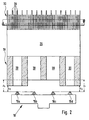
- FIG. 2 the representation of an atmospheric gas burner with a tiered training of the mixing tubes or Mixing pipe system.
- FIGS. 1a and 1b show a gas distributor device 10 which consists of a base part 12 and a lid-shaped closure part 14.
- gas nozzles 16a-f are distributed at regular intervals.
- the gas distribution device 10 is arranged opposite a mixing tube system 18 with individual mixing tubes 20, the gas nozzles 16a-f of the gas distribution device 10 being centrally opposite the openings of the individual mixing tubes 20 at a distance ⁇ n .
- the side of the base part 12 in which the gas nozzles 16a-f are arranged is of stepped construction.
- the gradation of the base part 12 results in different distances ⁇ n between the exit plane of the gas nozzles 16a-f and the entry plane of the injector tube openings.
- the two gas nozzles 16c, d arranged centrally on the base part 12 are at a distance ⁇ 1 from the entry plane of their corresponding mixing tube openings, while the gas nozzles 16b, e arranged therefrom on the left or right are at a distance ⁇ 2 from the entry plane of the mixing tube openings ,.
- the gas nozzles 16a, f arranged on the extreme left and right are spaced apart by a distance ⁇ 3 from the mixing tube openings, where ⁇ 1 > ⁇ 2 > ⁇ 3 .
- the different distances ⁇ n of the gas nozzles 16 to the mixing tube openings make it possible to control the primary air intake in a targeted manner.
- the gradation or the distances ⁇ n are selected such that in the edge regions of the mixing tube system 18 with the distances ⁇ 3 of the gas nozzles 16a, f from the entry plane of their corresponding mixing tube openings, via which exits from the gas nozzles 16a, f Gas flow the smaller amount of combustion air is entrained.
- the correspondingly larger distances ⁇ 2 and ⁇ 1 are used to inject more combustion air into the mixing tubes 20 via the gas nozzles 16b, e and 16c, d, respectively.
- Such an influence on the air ratio can be used in particular in gas-powered heating devices which have a closed combustion chamber and where all the combustion air required for superstoichiometric combustion is already provided with the primary air intake. Devices of this type show the tendency that, with the gas nozzles at an equal distance from the mixing tube openings, more combustion air is supplied in the edge regions.
- the lid-shaped is Locking part 14 of the gas distribution device 10 is a wedge 22 arranged, which when the base part 12 with the closure part 14 inside the base part 12 arranged channel 24 extends over its entire length, channel 24 being the gas supply for the individual Gas nozzles 16 takes over.
- the channel 24 protruding wedge 22 reduces the cross section of the Channel 24 Gas distribution channels caused by friction Pressure losses are compensated, so that at all gas nozzles 16 Gas distribution device 10 is the same gas pressure.
- Figure 2 shows the second embodiment of the invention, in which the same components are provided with the same reference numerals.
- the different distances ⁇ n between the gas nozzles 16a-d and the entry planes of the mixing tube openings are realized in that the mixing tubes 20 have different lengths or that the mixing tube system 18 is of stepped construction.
- the distances ⁇ 2 in the edge region of the mixing tube system 18 are smaller than the distances ⁇ 1 in the central region of the mixing tube system 18.
- the mixing pipe system 18 is followed by a mixing distributor space 26 for the fuel gas / air mixture, which is closed at the top by a burner deck 30 constructed from ribs 28.
- a burner deck 30 constructed from ribs 28.
- the fuel gas-air mixture flowing between the ribs 28 is ignited via an ignition device, not shown, and brought to combustion.
Landscapes
- Engineering & Computer Science (AREA)
- Chemical & Material Sciences (AREA)
- Combustion & Propulsion (AREA)
- Mechanical Engineering (AREA)
- General Engineering & Computer Science (AREA)
- Gas Burners (AREA)
Abstract
Description
Claims (7)
- Atmosphärischer Gasbrenner für ein Heizgerät mit einer mit Gasdüsen ausgestatteten Gasverteilervorrichtung, sowie mit Mischrohren, die den einzelnen Gasdüsen zugeordnet sind, so daß der aus den Gasdüsen austretende Gasstrom unter Ansaugung von Verbrennungsluft in die Mischrohre eintreten kann, sowie mit Mitteln zur Beeinflussung der Primärluftansaugung, dadurch gekennzeichnet, daß die Abstände ▵n zwischen den Gasdüsen (16) und der Eintrittsebene der Mischrohröffnungen unterschiedlich groß ausgebildet sind.
- Gasbrenner nach Anspruch 1, dadurch gekennzeichnet, daß die Abstände ▵n von der Mitte der Gasverteilervorrichtung (10) nach außen zu beiden Seiten hin abnehmen.
- Gasbrenner nach Anspruch 1 oder 2, dadurch gekennzeichnet, daß die Gasverteilervorrichtung (10) gestuft ausgebildet ist, so daß sich die unterschiedlichen Abstände ▵n zwischen den Gasdüsen (16) und der Eintrittsebene der Mischrohröffnungen ergeben.
- Gasbrenner nach Anspruch 1 oder 2, dadurch gekennzeichnet, daß die Mischrohre (20) gestuft ausgebildet sind, so daß sich die unterschiedlichen Abstände ▵n zwischen den Gasdüsen (16)und der Eintrittsebene der Mischrohröffnungen ergeben.
- Gasverteilervorrichtung für einen atmosphärischen Gasbrenner mit einem Basisteil, in dem mehrere Gasdüsen verteilt angeordnet sind, sowie mit einem Kanal für die Versorgung der Gasdüsen mit Brenngas, dadurch gekennzeichnet, daß das Basisteil (12) auf der Seite der Gasdüsen (16) gestuft ausgebildet ist.
- Gasverteilervorrichtung nach Anspruch 5, dadurch gekennzeichnet, daß der Kanalquerschnitt vom Kanalanfang zum Kanalende hin abnimmt.
- Gasverteilervorrichtung nach Anspruch 5 oder 6, dadurch gekennzeichnet, daß der im Basisteil (12) ausgebildete u-förmige Kanal (24) durch ein mit einem Keil (22) versehenes deckelförmiges Verschlußteil (14) abgeschlossen ist, wobei der Keil (22) in den Kanal (24) so hineinragt, daß sich der Querschnitt zum Kanalende hin verkleinert.
Applications Claiming Priority (2)
| Application Number | Priority Date | Filing Date | Title |
|---|---|---|---|
| DE19905789 | 1999-02-12 | ||
| DE1999105789 DE19905789B4 (de) | 1999-02-12 | 1999-02-12 | Atmosphärischer Gasbrenner sowie Gasverteilervorrichtung für einen Gasbrenner |
Publications (1)
| Publication Number | Publication Date |
|---|---|
| EP1028287A1 true EP1028287A1 (de) | 2000-08-16 |
Family
ID=7897233
Family Applications (1)
| Application Number | Title | Priority Date | Filing Date |
|---|---|---|---|
| EP00102842A Withdrawn EP1028287A1 (de) | 1999-02-12 | 2000-02-11 | Atmosphärischer Gasbrenner sowie Gasverteilervorrichtung für einen Gasbrenner |
Country Status (2)
| Country | Link |
|---|---|
| EP (1) | EP1028287A1 (de) |
| DE (1) | DE19905789B4 (de) |
Cited By (4)
| Publication number | Priority date | Publication date | Assignee | Title |
|---|---|---|---|---|
| EP1355110A1 (de) * | 2002-04-18 | 2003-10-22 | Furigas Assen B.V. | Brenneranordnung |
| DE202006002336U1 (de) * | 2006-02-13 | 2007-03-29 | Viessmann Werke Gmbh & Co Kg | Atmosphärischer Gasbrenner |
| ITMO20130184A1 (it) * | 2013-06-25 | 2014-12-26 | Worgas Bruciatori Srl | Metodo per ottenereun collettore per bruciatori a gas e collettore ottenuto. |
| IT202100032039A1 (it) * | 2021-12-21 | 2023-06-21 | Beckett Thermal Solutions S R L | Modulo bruciatore |
Families Citing this family (3)
| Publication number | Priority date | Publication date | Assignee | Title |
|---|---|---|---|---|
| DE20016808U1 (de) | 2000-09-29 | 2000-12-21 | Viessmann Werke GmbH & Co., 35108 Allendorf | Gasverteiler |
| DE10157086C2 (de) * | 2001-11-21 | 2003-11-13 | Viessmann Werke Kg | Gasverteiler |
| EP1426682A1 (de) * | 2002-12-02 | 2004-06-09 | Vaillant GmbH | Brenngasleiste mit Brenngasdüsen für einen Injektorbrenner |
Citations (6)
| Publication number | Priority date | Publication date | Assignee | Title |
|---|---|---|---|---|
| FR339111A (fr) * | 1903-10-19 | 1904-11-14 | Georges Jean Louis Edouard Lan | Bruleur à canalisations séparées d'air et de combustible sans emploi d'énergie extérieure |
| US3799452A (en) * | 1972-06-22 | 1974-03-26 | Vaillant Joh Kg | Premixing gas burner |
| DE2649454A1 (de) * | 1976-10-29 | 1978-05-03 | Ruhrgas Ag | Kochstellenbrenner fuer gasherde |
| DE3840976A1 (de) * | 1987-12-11 | 1989-06-22 | Vaillant Joh Gmbh & Co | Verfahren zum verteilen eines brennstoff-luft-gemisches im brennraum eines brennerbeheizten geraetes, z. b. eines wasserheizers, sowie brenner zur durchfuehrung dieses verfahrens |
| DE9302238U1 (de) * | 1992-02-18 | 1993-03-25 | Joh. Vaillant Gmbh U. Co, 5630 Remscheid | Gas-Verteileinrichtung |
| AT398477B (de) * | 1992-09-24 | 1994-12-27 | Vaillant Gmbh | Düsenplatte eines atmosphärischen gasbrenners |
Family Cites Families (3)
| Publication number | Priority date | Publication date | Assignee | Title |
|---|---|---|---|---|
| NL181601C (nl) * | 1977-07-27 | Stelrad Group Ltd | Gasbrander voor constante vlamgrootte. | |
| DE3811477A1 (de) * | 1987-04-15 | 1988-10-27 | Vaillant Joh Gmbh & Co | Atmosphaerischer gasbrenner |
| US5205851A (en) * | 1990-10-12 | 1993-04-27 | Sumitomo Electric Industries, Ltd. | Method and apparatus for producing optical fiber coupler |
-
1999
- 1999-02-12 DE DE1999105789 patent/DE19905789B4/de not_active Expired - Fee Related
-
2000
- 2000-02-11 EP EP00102842A patent/EP1028287A1/de not_active Withdrawn
Patent Citations (6)
| Publication number | Priority date | Publication date | Assignee | Title |
|---|---|---|---|---|
| FR339111A (fr) * | 1903-10-19 | 1904-11-14 | Georges Jean Louis Edouard Lan | Bruleur à canalisations séparées d'air et de combustible sans emploi d'énergie extérieure |
| US3799452A (en) * | 1972-06-22 | 1974-03-26 | Vaillant Joh Kg | Premixing gas burner |
| DE2649454A1 (de) * | 1976-10-29 | 1978-05-03 | Ruhrgas Ag | Kochstellenbrenner fuer gasherde |
| DE3840976A1 (de) * | 1987-12-11 | 1989-06-22 | Vaillant Joh Gmbh & Co | Verfahren zum verteilen eines brennstoff-luft-gemisches im brennraum eines brennerbeheizten geraetes, z. b. eines wasserheizers, sowie brenner zur durchfuehrung dieses verfahrens |
| DE9302238U1 (de) * | 1992-02-18 | 1993-03-25 | Joh. Vaillant Gmbh U. Co, 5630 Remscheid | Gas-Verteileinrichtung |
| AT398477B (de) * | 1992-09-24 | 1994-12-27 | Vaillant Gmbh | Düsenplatte eines atmosphärischen gasbrenners |
Cited By (6)
| Publication number | Priority date | Publication date | Assignee | Title |
|---|---|---|---|---|
| EP1355110A1 (de) * | 2002-04-18 | 2003-10-22 | Furigas Assen B.V. | Brenneranordnung |
| DE202006002336U1 (de) * | 2006-02-13 | 2007-03-29 | Viessmann Werke Gmbh & Co Kg | Atmosphärischer Gasbrenner |
| ITMO20130184A1 (it) * | 2013-06-25 | 2014-12-26 | Worgas Bruciatori Srl | Metodo per ottenereun collettore per bruciatori a gas e collettore ottenuto. |
| IT202100032039A1 (it) * | 2021-12-21 | 2023-06-21 | Beckett Thermal Solutions S R L | Modulo bruciatore |
| EP4202298A1 (de) * | 2021-12-21 | 2023-06-28 | Beckett Thermal Solutions S.R.L. | Brennermodul |
| EP4202298B1 (de) | 2021-12-21 | 2024-03-20 | Beckett Thermal Solutions S.R.L. | Brennermodul |
Also Published As
| Publication number | Publication date |
|---|---|
| DE19905789A1 (de) | 2000-08-24 |
| DE19905789B4 (de) | 2004-11-04 |
Similar Documents
| Publication | Publication Date | Title |
|---|---|---|
| DE2936426C2 (de) | ||
| DE69315804T2 (de) | Gasbeheiztes Gerät mit atmosphärischem Brenner | |
| EP0598189B1 (de) | Zerstäuber für einen Ölbrenner | |
| DE2832708C2 (de) | ||
| DE2660865C3 (de) | Verbrennungseinrichtung zur Durchführung einer zweistufigen Verbrennung unter Abgasrückführung | |
| EP1130315B1 (de) | Atmosphärischer Gasbrenner | |
| DE102020121597A1 (de) | Verfahren und Anordnung zur pneumatischen Gemischbildung bei einem Vormischbrenner | |
| EP1028287A1 (de) | Atmosphärischer Gasbrenner sowie Gasverteilervorrichtung für einen Gasbrenner | |
| WO2002052201A1 (de) | Brenner mit gestufter brennstoffeindüsung | |
| DE19822336C2 (de) | Vorrichtung zum Betreiben eines atmosphärischen, insbesondere vollvormischenden Gasbrenners | |
| EP0829678B1 (de) | Kanalbrenner und Verfahren zum Aufheizen eines strömenden Gases | |
| DE19905791C2 (de) | Atmosphärischer Gasbrenner | |
| DE69307816T2 (de) | Atmospherischer Gasbrenner zur Verbrennung mit niedrigem Stickoxiden- und Kohlenoxiden-Gehalt | |
| EP0866270B1 (de) | Gasheizgerät, insbesondere für Wassererhitzer | |
| AT399382B (de) | Atmosphärischer vormisch-gasbrenner | |
| DE3826279C2 (de) | Gasbrenner mit einer Brennerkammer | |
| EP0529042B1 (de) | Vormischgasbrenner | |
| EP0602404B1 (de) | Gasturbinenbrennkammer | |
| DE19750870C2 (de) | Verfahren zur Überwachung der Flammenposition an einem regelbaren atmosphärischen Gasbrenner für Heizgeräte, insbesondere Wassererhitzer | |
| DE4311009A1 (de) | Verfahren und Anordnung zum Zuführen von Ausbrandluft in den Rauchgasstrom eines kohlenstaubgefeuerten Dampfkessels | |
| DE8633823U1 (de) | Atmosphärischer Gasbrenner zur Regelung der Luftzahl des einem solchen Gasbrenner zugeführten Gas-Luft-Gemisches | |
| DE19810750A1 (de) | Verfahren und Vorrichtung zum Betreiben eines atmosphärischen Gasbrenners | |
| DE3440050A1 (de) | Kraftstoffsparvorrichtung | |
| EP0509229A2 (de) | Steuer- bzw. Regelvorrichtung für Gasbrenner mit einem Gebläse zum Zuführen der Verbrennungsluft | |
| DE4301664A1 (de) | Glasschmelzofen |
Legal Events
| Date | Code | Title | Description |
|---|---|---|---|
| PUAI | Public reference made under article 153(3) epc to a published international application that has entered the european phase |
Free format text: ORIGINAL CODE: 0009012 |
|
| AK | Designated contracting states |
Kind code of ref document: A1 Designated state(s): DE ES FR GB IT NL |
|
| AX | Request for extension of the european patent |
Free format text: AL;LT;LV;MK;RO;SI |
|
| 17P | Request for examination filed |
Effective date: 20010216 |
|
| AKX | Designation fees paid |
Free format text: DE ES FR GB IT NL |
|
| 17Q | First examination report despatched |
Effective date: 20010907 |
|
| GRAH | Despatch of communication of intention to grant a patent |
Free format text: ORIGINAL CODE: EPIDOS IGRA |
|
| GRAH | Despatch of communication of intention to grant a patent |
Free format text: ORIGINAL CODE: EPIDOS IGRA |
|
| STAA | Information on the status of an ep patent application or granted ep patent |
Free format text: STATUS: THE APPLICATION IS DEEMED TO BE WITHDRAWN |
|
| 18D | Application deemed to be withdrawn |
Effective date: 20030902 |