EP1028221A2 - Vorrichtung zum Öffnen und Schliessen einer Fensterjalousie - Google Patents
Vorrichtung zum Öffnen und Schliessen einer Fensterjalousie Download PDFInfo
- Publication number
- EP1028221A2 EP1028221A2 EP00102632A EP00102632A EP1028221A2 EP 1028221 A2 EP1028221 A2 EP 1028221A2 EP 00102632 A EP00102632 A EP 00102632A EP 00102632 A EP00102632 A EP 00102632A EP 1028221 A2 EP1028221 A2 EP 1028221A2
- Authority
- EP
- European Patent Office
- Prior art keywords
- runner
- louver
- opening
- stopper
- window blind
- Prior art date
- Legal status (The legal status is an assumption and is not a legal conclusion. Google has not performed a legal analysis and makes no representation as to the accuracy of the status listed.)
- Granted
Links
- 239000000969 carrier Substances 0.000 claims description 8
- 230000007246 mechanism Effects 0.000 description 17
- 238000010276 construction Methods 0.000 description 5
- 230000004048 modification Effects 0.000 description 5
- 238000012986 modification Methods 0.000 description 5
- 210000000078 claw Anatomy 0.000 description 4
- 238000000034 method Methods 0.000 description 4
- 230000008569 process Effects 0.000 description 4
- 230000009471 action Effects 0.000 description 3
- 230000000903 blocking effect Effects 0.000 description 2
- 230000007704 transition Effects 0.000 description 2
- 238000007792 addition Methods 0.000 description 1
- XAGFODPZIPBFFR-UHFFFAOYSA-N aluminium Chemical compound [Al] XAGFODPZIPBFFR-UHFFFAOYSA-N 0.000 description 1
- 229910052782 aluminium Inorganic materials 0.000 description 1
- 238000013459 approach Methods 0.000 description 1
- 230000015556 catabolic process Effects 0.000 description 1
- 238000006731 degradation reaction Methods 0.000 description 1
- 230000013011 mating Effects 0.000 description 1
- 239000011347 resin Substances 0.000 description 1
- 229920005989 resin Polymers 0.000 description 1
- 239000007787 solid Substances 0.000 description 1
Images


Classifications
-
- E—FIXED CONSTRUCTIONS
- E06—DOORS, WINDOWS, SHUTTERS, OR ROLLER BLINDS IN GENERAL; LADDERS
- E06B—FIXED OR MOVABLE CLOSURES FOR OPENINGS IN BUILDINGS, VEHICLES, FENCES OR LIKE ENCLOSURES IN GENERAL, e.g. DOORS, WINDOWS, BLINDS, GATES
- E06B9/00—Screening or protective devices for wall or similar openings, with or without operating or securing mechanisms; Closures of similar construction
- E06B9/24—Screens or other constructions affording protection against light, especially against sunshine; Similar screens for privacy or appearance; Slat blinds
- E06B9/26—Lamellar or like blinds, e.g. venetian blinds
- E06B9/36—Lamellar or like blinds, e.g. venetian blinds with vertical lamellae ; Supporting rails therefor
- E06B9/362—Travellers; Lamellae suspension stems
- E06B9/364—Operating mechanisms therein
-
- Y—GENERAL TAGGING OF NEW TECHNOLOGICAL DEVELOPMENTS; GENERAL TAGGING OF CROSS-SECTIONAL TECHNOLOGIES SPANNING OVER SEVERAL SECTIONS OF THE IPC; TECHNICAL SUBJECTS COVERED BY FORMER USPC CROSS-REFERENCE ART COLLECTIONS [XRACs] AND DIGESTS
- Y10—TECHNICAL SUBJECTS COVERED BY FORMER USPC
- Y10S—TECHNICAL SUBJECTS COVERED BY FORMER USPC CROSS-REFERENCE ART COLLECTIONS [XRACs] AND DIGESTS
- Y10S160/00—Flexible or portable closure, partition, or panel
- Y10S160/90—Vertical type venetian blind
Definitions
- the present invention relates to an opening and closing device for a window blind, in which respective louvers are suspended on a plurality of runners, for closing the window blind by widening distances between the louvers in a louver group and opening the window blind by stacking the louvers in the louver group.
- a top runner is pulled by a drive cord to sequentially draw the louvers from one by one from the louver attached to the top runner for folding the louver to open the window blind.
- the louvers in the louver group are moved in a condition stacked at the leading end of opening to cause substantial load on a drive shaft for opening and closing the window blind, to damage the runner and/or drive shaft by wearing, or to degrade appearance.
- louvers when a tilt shaft is pivoted by pulling a tilt cord, a carrier of all of runners extending through the tilt shaft are rotated simultaneously to vary angles of the louvers all together.
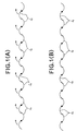
- the louvers When the louvers are placed in closed condition, the louvers are partially overlapped in back and forth direction constantly as viewed from the front side.
- louvers are overlapped with fitting the curves with each other as shown in Fig. 1A.
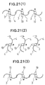
- the front and back surfaces of the louvers 4 are reversed by pivoting in the direction shown by arrow over about 180° all together by the tilt shaft, curves are mated in back-to back relationship as shown in Fig. 1B. In either case of Figs.
- an opening and closing device for a window blind in which louvers are hanged on carriers respectively carried by runners in a runner group traveling along a rail for opening and closing the group of louvers, and the carriers are rotated by a tilt shaft extending through the runner group for varying orientation of the louvers in unison, comprises:
- the belt connecting pin actuating projection is projected to drive the belt connection pin of the second runner to retract and to release from the runner connecting portion of the runner driving endless belt to stop the second runner in the condition stacked with the end runner.
- the runner driving endless belt is further driven in the same direction to circulate to stop the third runner with neatly stacking on the second runner.
- the belt connecting pin actuating projection is projected to drive the belt connection pin of the third runner to retract to release from the runner connecting portion of the runner driving endless belt to stop the third runner in the condition stacked with the end runner.
- the louver group can be sequentially folded forwardly from the end runner.
- the runner connecting portions of the runner driving endless belt may be holes.
- a pinion rotatable about the tilt shaft for varying orientation of the louvers in the louver group in unison and a cam for rotating the pinion with engaging with the belt connecting pin actuating projection projecting from the receptacle opening may be provided within each runner and a rack portion meshing with the pinion may be provided on the belt connecting pin.
- a cam engaging with the belt connecting pin actuating projection projecting from the receptacle opening for retracting the belt connecting pin against the spring may be provided in the belt connecting pin.
- An end stopper is fixed to one end in the rail and a belt connecting pin actuating projection may be provided for retracting the belt connecting pin by projecting into the end runner into the receptacle opening.
- a runner restricting stopper is provided on a top runner arranged at the leading end among the runners for restricting travel of the top runner relative to the rail and releasing from restricted state
- stopper actuating member may be provided on the top runner for actuating the runner restricting stopper to a travel restricting position when the louvers may be oriented in closing orientation (in the orientation to be parallel to the axis of the rail) and for actuating the runner restricting stopper to released position when the louver may be oriented in opening orientation (in the orientation intersecting with the axis of the rail).
- a propeller may be fixed on the carrier of each runner, and louver reversing member may be projected from a louver reversing endless belt which can circulate along the rail for sequentially rotating each individual carrier together with the propeller by colliding with the propeller.
- louvers when the louver reversing endless belt is circulated, the louver reversing member projected from the louver reversing endless belt sequentially collides on the propeller of the carriers of the runner group to sequentially rotates respective individual carrier without using the tilt shaft.
- the louvers can be reversed the front and rear surfaces individually in one-by-one basis.
- a propeller rotation stopper restricting rotation of the propeller at an orientation with a given angle relative to the rail may be provided on each runner, and a propeller stopper releasing member releasing the propeller rotation stopper to permit rotation of the propeller may be provided on the louver reversing member.
- the louver reversing endless belt may be wound around sprocket wheels rotatably supported on the rail, a louver reversal restricting stopper for restricting rotation of the sprocket and releasing restriction is provided on the rail, and a stopper releasing member for retracting the louver reversal restricting stopper to a released position is provided on the top runner.
- the louvers in the louver group can be drawn frontwardly from the end runner side sequentially conversely from the prior art, a problem of damaging of the runner or the drive shaft due to wearing can be resolved to provide good appearance when the window blind is opened to the midway.
- a runner restricting stopper which can restrict travel of the top runner relative the rail and releasing restriction is provided on the top runner and a stopper actuating member may be provided on the carrier of the top runner for actuating the runner restricting stopper to traveling restricting position when the louver is oriented in closing orientation (orientation to be parallel to the axis of the rail) and for actuating the runner restricting stopper to released position when the louver is oriented in opening orientation (orientation to intersect with the axis of the rail).
- the louver may be reversed S shaped cross section.
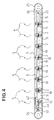
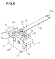
- a plurality of runners 2 in a form shown in Figs. 5 and 6, are mounted within a box shaped rail 1 in slidable fashion.
- a carrier 3 mounted on each individual runner 2 suspends a louver 4.
- a group of runners 2 may slidingly travel along the rail 1 by means of an endless belt 5 for driving the runner, which endless belt circulates within the rail 1.
- a tilt shaft 6 extending through all of runners 2, all of the carriers 3 carried by respective runners 2 are rotated simultaneously for varying orientation of all of the louvers 4 all together.
- each louver 4 has a reversed S shaped cross section.
- orientation of the group of louvers 4 relative to the group of runners 2 are shown separately from the group of the runners 2.
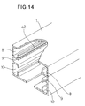
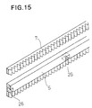
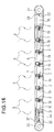
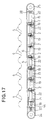
- the rail 1 is molded into the boxed shaped configuration with aluminum and defines three stages of guide portions on both sides as shown in Figs. 1 and 14. Namely, the rail 1 defines an upper belt guide portion 8 guiding the endless belt 7 for reversing the louvers, an intermediate runner guide portion 9 for guiding the group of the runners 2, and a lower belt guide portion 10 for guiding the endless belt 5 for driving the runners. In Fig. 15, parts of the endless belt 5 for driving the runners and the endless belt 7 for reversing the louvers are shown.
- the group of runners 2 are mounted within the rail 1 for sliding movement in horizontal direction by slidably engaging the projecting portions 11 on both side surfaces with the runner guide portion 9. It should be noted that rollers rotating within the runner guide portion 9 may be rotatably supported on the runners 2 in place of the projecting portion 11.
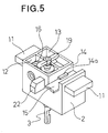
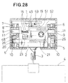
- Each runner 2 is molded into a box shaped configuration with a resin as shown in Figs. 5 and 6 and defines a carrier rotating mechanism chamber 12 and a belt connecting pin projecting and retracting mechanism chamber 13 in alignment along the runner traveling direction, and further defines a connecting recess portion 14.
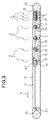
- the group of runners 2 are chained with each other with a given interval by engaging a tip end claw portion 15a of a connecting piece 15 projecting from own connecting recess portion 14 with a projection 14a in the connecting recess portion 14 of the adjacent runner 2 as shown in Figs. 3 and 4.
- a direction to which the group of louvers 4 are extracted by increasing distances between the runners 2 and whereby closing the window blind will be referred to as forward
- a direction to which the group of louvers 4 are retracted by reducing the distances between the runners 2 and whereby opening the window blind will be referred to as backward (toward right in Figs. 3 and 4).
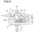
- a worm gear 16 formed integrally with the tilt shaft 6 extending therethrough and a part of the carrier 3 are housed.
- the worm gear 16 meshes with a worm gear 17 provided on the carrier 3.
- a pinion 18 through which the tilt shaft 6 extends, rotatable about the latter, a cam 18a provided integrally with the pinion 18, a belt connecting pin 20 having a rack portion 20a meshing with the pinion 18 to be projected and retracted associating with rotation of the pinion 18, and a spring 21 for biasing the belt connecting pin 20 in projecting direction.
- each runner 2 On the front surface of each runner 2, the belt connection pin actuating projection 22 for actuating the belt connection pin 20 of one preceding runner 2 is projected integrally, as shown in Fig. 5. On the back surface of each runner 2 as opposite surface, a receptacle opening 23 is formed for accommodating a tip end portion of the belt connection pin actuating projection 22 of immediately trailing runner 2 within the belt connection pin projecting and retracting mechanism chamber 13 for engagement with the cam 18a, as shown in Fig. 6.
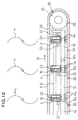
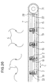
- the endless belt 5 for driving the runner on the rail side is wound around sprocket wheels 24 and 25 rotatably supported at both end portions of the rail 1 as shown in Figs. 3 and 4.
- the endless belt 5 is circulated along the lower belt guide portion 10.
- a plurality of runner connection holes 26 are provided at regular interval (corresponding to the interval of the connecting pieces 15) for accommodating the tip end portion of respective belt connection pins 20 in releasable fashion.
- an end stopper 28 which is not movable, is fixedly provided in the vicinity of the right side sprocket wheel 25, in the vicinity of the right side sprocket wheel 25, an end stopper 28 which is not movable, is fixedly provided. Even on the end stopper 28, the belt connection pin actuating projection 22 and the connecting piece 15 are projected in the similar manner as the belt connection pin actuating projection 22 of the runner 2. The end stopper 28 extends through the tilt shaft 6.
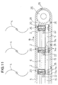
- the endless belt 5 for driving the runner for closing the window blind is circulated in the direction of arrow A of Fig. 3, the runner 2 projecting the belt connection pin 20 into the runner connection hole 26 sequentially travels frontwardly as being drawn by the endless belt 5 driving the runner.
- the belt connection pin 20 of all runners 2 in the runner group is arranged in equal interval with projecting the belt connection pins 20 into the runner connection holes 26.
- the runners 2 in the runner group are driven to travel backwardly.
- the belt connection pin actuating projection 22 of the end stopper 28 enters into the receptacle opening 23 of the end runner 2 to engage with the cam 18a.
- the pinion 18 rotates about the tilt shaft 6.
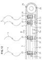
- the belt connection pin 20 is then released from the runner connection hole 26 against a biasing force of the spring 21. Therefore, the end runner 2 at the rearmost position is initially separated from the endless belt 5 for driving the runner to stop as shown in Fig. 12.
- the operation set forth above is performed sequentially in one-by-one basis. Therefore, the group of louvers 4 are sequentially folded from the rear end (from right end) instead of folded from the front end as in the prior art as shown in Figs. 10 to 13.
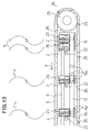
- the endless belt 5 for driving the runner is circulated in the direction of arrow A as shown in Fig. 13. Then, the runner 2 which maintains the belt connection pin 20 thereof projecting into the runner connection hole 26 is driven frontwardly as drawn by the endless belt 5 for driving the runner to be placed in a condition where the immediately trailing runner 2 is drawn through the connecting piece 15.
- the belt connection pin actuating projection 22 of further immediately trailing runner 2 is withdrawn from the receptacle opening 23 of the immediately trailing runner 2. Therefore, the belt connection pin 20 of the drawn runner 2 is placed in a condition again projected by the action of the spring 21 to project the endless belt 5 for driving the runner 2 into the next runner connection hole 26. Then, the runner 2 is drawn by the endless belt 5 for driving the runner 2 via the connecting piece 15.
- the group of the louvers 4 transits from the state of Fig. 13 to respective states of Figs. 12, 11 and 10 to close the window blind.
- two vane propeller 19 is fixed to the carrier 3 for integral rotation therewith in the orientation intersecting with the orientation of the louver 4, as shown in Figs. 5 and 6.
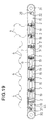
- the endless belt 7 for reversing the louver on the rail side is wound around sprocket wheels 30 and 31 rotatably supported at both end portions of the rail 1 as shown in Fig. 16.
- the endless belt 7 is circulated along the upper belt guide portion 8.
- louvers 4 are mated in back-to-back relationship. Reversing operation of the louver 4 is diagrammatically illustrated as shown in Figs. 21(1) to 21(3).
- louver reversing member 32 On the endless belt 7 for reversal of the louver, a louver reversing member 32 is fixed in inwardly projected fashion as shown in Fig. 18 in order to reverse each of the louver 4 in one-by-one basis from the condition shown in Fig. 18.
- the louver reversing portion 32 is sequentially collide to the propeller 19 of the runner 2.
- the carrier 3 When the propeller 19 collides on the louver reversing member 32, the carrier 3 is rotated. In this case, the worm gear 17 provided on the carrier 3 is meshed with the worm gear 16 for integral rotation together with the tilt shaft 6 as set forth above. Due to slip (play) between the worm gear 17 and the worm gear 16, the tilt shaft 6 does not rotate for large load loaded on the tilt shaft 6, when only one carrier 3 is rotated. Only one carrier 3 whose propeller 19 is in collision with the louver reversing member 32, is rotated to vary orientation of one louver 4.
- the endless belt 7 for reversing the louver is circulated in the direction of arrow C to collide the louver reversing member 32 to the propeller 19 from the runner 2 at the right end to the runner on the left side, sequentially in one-by-one basis.
- the runner 2, on which the louver reversing member 32 collides, is rotated the carrier 3 thereof in clockwise direction to orient the louver 4 intersecting with the tilt shaft 6.
- louvers 4 in the louver group it is appropriate to perform reversal of the louvers 4 in the louver group in one-by-one basis when the window blind is fully closed and the distance between the louvers becomes maximum.
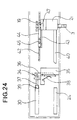
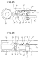
- rotation of the left side sprocket wheel 30 is restricted by means of the louver reversal restricting stopper mechanism 34, as shown in Figs. 23 to 26.
- the louver reversal restricting stopper mechanism 34 discusses discussion will be given for the louver reversal restricting stopper mechanism 34.
- a stopper base 35 On the inner side (within a rail side cap) of the left end portion of the rail 1, a stopper base 35 is fixed.
- a lever 36 is pivotably supported on the stopper base 35.
- a louver reversal restricting stopper 37 is provided for back and forth movement toward the sprocket wheel 30 on left side as guided by the stopper base 35. Then, the lever 36 and the stopper 37 are connected by pin .
- the lever 36 is biased by a spring 38. Then, a gear portion 39 provided at the tip end of the stopper 37 is normally meshed with the sprocket wheel 30 on left side as shown in Figs. 23 and 24.
- a bar shaped stopper releasing member 40 is projected frontwardly in horizontal direction.
- the stopper releasing member 40 pushes the lower end portion of the lever 36 through a guide hole 41 defined in the stopper base 35 to cause pivot motion of the lever 36 against the spring 38.
- the stopper 37 is retracted to release a teeth portion 39 from the sprocket wheel 30 on the left side as shown in Figs. 25 and 26 to permit rotation of the sprocket wheel 30 and whereby to permit circulation of the endless belt 7 for reversal of the louver.
- the orientation of the louvers in the louver group can be sequentially reversed in one-by-one basis.
- louver 4 Since the louver 4 is in reversed S shaped configuration in cross section, upon opening the window blind, if the louvers 4 are moved backwardly with maintaining a condition where the louvers 4 in the louver group are oriented to be parallel to the rail 1 to overlap the portions thereof, movement can be performed smoothly. Therefore, when the orientation of the louvers 4 in the louver group is placed in the condition to be parallel to the rail 1 with overlapping the portions thereof, a runner restricting stopper mechanism 41 restricting travel of the top runner 2t is provided in the top runner 2t in order to restrict opening and closing operation of the window blind. Finally, the runner restricting stopper mechanism 41 will be discussed.
- a saw tooth portion 42 is provided on the inner side surface of the rail 1.
- a stopper base plate 43 is fixed on the top runner 2t.
- a runner restricting stopper 44 having a claw portion 44a is pivotably mounted by means of a pin 45 for pivot motion in horizontal direction.
- the stopper 44 is biased in a direction for preventing the claw portion 44a from engaging with the saw toothed member 42 of the rail 1 by a spring 46 mounted on the stopper base plate 43.
- a cam (stopper actuating member) 47 which is smaller than the propeller 19 is fixed in the orientation with the propeller 19.
- the stopper 44 Since the cam 47 does not push the stopper 44 when the louver is oriented intersecting with the tilt shaft 6 as shown in Figs. 4 and 16, as shown in Fig. 23, the stopper 44 is retracted to the position not engaging with the saw toothed member 42 of the rail 1 by the action of the spring 46. Accordingly, in this case, travel of the top runner 2t is permitted to enable opening and closing of the window blind.
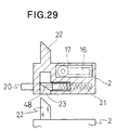
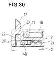
- a cam 48 is fixed on the upper surface of the belt connection pin 20 per se .
- the cam 48 and the belt connection pin 20 have tilting portion.
- the belt connection pin actuating projection 22 of the immediately trailing runner 2 enters into the receptacle opening 23 to engage with the cam 48 as shown in Figs. 29 and 30.
- the belt connection pin 22 is directly retracted by the belt connection pin actuating projection 22 against the spring 21 to be withdrawn from the runner connection hole 26 of the endless belt 5 for driving the runner.
- the mechanism to retract the belt connection pin 22 to withdraw from the runner connection hole 26 can be simpler than that of the foregoing embodiment.
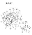
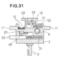
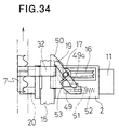
- a propeller rotation stopper 49 restricting rotation of the propeller 19 is mounted in the following manner in each runner 2. Also, on tip end portion of the louver reversing member 32, a propeller rotation stopper releasing member 50 is fixed for releasing restriction by the propeller rotation stopper 49.
- the propeller rotation stopper 49 is fixed on the slider 51 which is slidably loaded in each runner 2, as shown in Fig. 31.
- the slider 51 is biased to a predetermined position by a spring 52.
- a lever 53 is integrally fixed to the propeller 19 for rotation therewith.
- the tip end of the lever 53 contacts with a projecting portion 49a of the propeller rotation stopper 49, as shown in Figs. 27 and 32.
- the propeller 19 is restricted rotation in the orientation perpendicular to the centerline of the rail 1. At this time, the orientation of the louver 4 becomes parallel to the rail 1.
- the propeller rotation stopper releasing member 50 engages with the propeller rotation stopper 49 as shown in Fig. 33 to retract the propeller rotation stopper 49 against the spring 52 as shown in Fig. 33 to release the projecting portion 49a of the propeller rotation stopper 49 and the tip end of the lever 53.
- the propeller 19 is permitted to rotate.
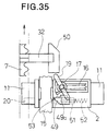
- louver reversing member 32 When the louver reversing member 32 is further traveled, it collides on the propeller 19 as shown in Fig. 34 to rotate the propeller 19 in clockwise direction to reverse the louver 4. When the louver reversing member 32 is further driven to travel as shown in Fig. 35, the similar operation is performed in the next runner 2 to reverse the louvers 4 sequentially.
- the runner connecting portion of the endless belt 5 for driving the runner is not limited to the hole (runner connection hole 26) as in the foregoing embodiments, but can be a projecting portion or step portion to engage with the belt connection pin 20.
- the louvers in the louver group can be drawn frontwardly from the end runner side sequentially conversely from the prior art, a problem of damaging of the runner or the drive shaft due to wearing can be resolved to provide good appearance when the window blind is opened to the midway.
- opening and closing of the window blind can be performed without interference even when the shaped louvers, such as the louver having S shaped cross section, are employed.
- the louvers can be overlapped with neatly fitting the front and rear surfaces even when the front and rear surfaces are reversed even when the shaped louvers, such as the louver having S shaped cross section, are employed.
- the louvers in the louver group can be neatly oriented in the predetermined orientation to assure reversal of the louver by the louver reversing member.
- the endless belt for reversing the louver cannot be circulated by the action of the louver reversal restricting stopper, and when the top runner reaches the terminal end to certainly provide sufficient interval between the louvers, restriction of the louver reversal restricting stopper can be released to permit circulation of the endless belt for reversing the louver to smoothly reversing the front and rear surfaces individually and sequentially.
- the present invention can avoid such problem.
Landscapes
- Engineering & Computer Science (AREA)
- Structural Engineering (AREA)
- Architecture (AREA)
- Civil Engineering (AREA)
- Blinds (AREA)
- Specific Sealing Or Ventilating Devices For Doors And Windows (AREA)
Applications Claiming Priority (2)
| Application Number | Priority Date | Filing Date | Title |
|---|---|---|---|
| JP3347299 | 1999-02-10 | ||
| JP11033472A JP2995301B1 (ja) | 1999-02-10 | 1999-02-10 | ブラインドのル―バ―反転装置 |
Publications (3)
| Publication Number | Publication Date |
|---|---|
| EP1028221A2 true EP1028221A2 (de) | 2000-08-16 |
| EP1028221A3 EP1028221A3 (de) | 2002-10-09 |
| EP1028221B1 EP1028221B1 (de) | 2004-04-21 |
Family
ID=12387498
Family Applications (1)
| Application Number | Title | Priority Date | Filing Date |
|---|---|---|---|
| EP00102632A Expired - Lifetime EP1028221B1 (de) | 1999-02-10 | 2000-02-08 | Vorrichtung zum Öffnen und Schliessen einer Fensterjalousie |
Country Status (4)
| Country | Link |
|---|---|
| US (1) | US6240998B1 (de) |
| EP (1) | EP1028221B1 (de) |
| JP (1) | JP2995301B1 (de) |
| DE (1) | DE60009967T2 (de) |
Cited By (1)
| Publication number | Priority date | Publication date | Assignee | Title |
|---|---|---|---|---|
| GB2360311A (en) * | 2000-02-01 | 2001-09-19 | Harris Parts Ltd | Carrier for vertical louvre blind |
Families Citing this family (10)
| Publication number | Priority date | Publication date | Assignee | Title |
|---|---|---|---|---|
| CN1313697C (zh) * | 2001-12-13 | 2007-05-02 | 有限会社美铃 | 百叶窗 |
| TWM251922U (en) * | 2004-01-14 | 2004-12-01 | Nien Made Entpr Co Ltd | Slat structure of venetian blind |
| AU2009100562B4 (en) * | 2009-06-10 | 2009-09-03 | Liftmaster Electronics Pty Ltd | Blind slat |
| CN203082144U (zh) * | 2012-12-21 | 2013-07-24 | 亿丰综合工业股份有限公司 | 百叶窗叶片角度的调整装置 |
| DE102013000238A1 (de) * | 2013-01-10 | 2014-07-10 | Hunter Douglas Industries Switzerland Gmbh | Strangelement, Profilstrang und/oder Verschattungsanlage mit einem solchen Strangelement |
| DE102013000237A1 (de) * | 2013-01-10 | 2014-07-10 | Hunter Douglas Industries Switzerland Gmbh | Schwenkgetriebe für eine Vertikaljalousie und Vertikaljalousie mit einem solchen Schwenkgetriebe |
| BE1022563B1 (nl) * | 2014-10-16 | 2016-06-02 | Renson Sunprotection Screens Nv | Lamelleninrichting |
| FR3049976B1 (fr) * | 2016-04-12 | 2022-08-05 | Biossun | Installation pour couvrir et decouvrir une surface a l'aide de lames orientables automotrices attelees |
| KR101930341B1 (ko) | 2017-08-04 | 2018-12-18 | 민인영 | 천장, 경사면, 곡면 및 외부 차양용 블라인드 장치 |
| JP7319902B2 (ja) * | 2019-12-12 | 2023-08-02 | 株式会社ニチベイ | 縦型ブラインド |
Citations (1)
| Publication number | Priority date | Publication date | Assignee | Title |
|---|---|---|---|---|
| JPH0714623A (ja) | 1993-06-23 | 1995-01-17 | Nec Corp | 接続用フレキシブルプリント基盤の収納構造 |
Family Cites Families (6)
| Publication number | Priority date | Publication date | Assignee | Title |
|---|---|---|---|---|
| US3079988A (en) * | 1962-05-23 | 1963-03-05 | Green Martin | Venetian blind |
| US5289863A (en) * | 1989-12-13 | 1994-03-01 | Schon B.V. | Apparatus for suspending lamellar sun-blinds or the like |
| CH682249A5 (de) * | 1991-01-24 | 1993-08-13 | Bratschi Silent Gliss | |
| US5275219A (en) * | 1991-12-12 | 1994-01-04 | Giacomel Jeffrey A | Environmentally interactive automatic closing system for blinds and other louvered window coverings |
| US5524692A (en) * | 1994-03-07 | 1996-06-11 | Back Tracker, Inc. | Vertical blind retraction apparatus with spacing control |
| US5865234A (en) * | 1996-08-12 | 1999-02-02 | Kabushiki Kaisha Nichibei | Vertical blind |
-
1999
- 1999-02-10 JP JP11033472A patent/JP2995301B1/ja not_active Expired - Fee Related
-
2000
- 2000-02-08 DE DE60009967T patent/DE60009967T2/de not_active Expired - Fee Related
- 2000-02-08 EP EP00102632A patent/EP1028221B1/de not_active Expired - Lifetime
- 2000-02-09 US US09/501,135 patent/US6240998B1/en not_active Expired - Fee Related
Patent Citations (1)
| Publication number | Priority date | Publication date | Assignee | Title |
|---|---|---|---|---|
| JPH0714623A (ja) | 1993-06-23 | 1995-01-17 | Nec Corp | 接続用フレキシブルプリント基盤の収納構造 |
Cited By (2)
| Publication number | Priority date | Publication date | Assignee | Title |
|---|---|---|---|---|
| GB2360311A (en) * | 2000-02-01 | 2001-09-19 | Harris Parts Ltd | Carrier for vertical louvre blind |
| GB2360311B (en) * | 2000-02-01 | 2003-08-06 | Harris Parts Ltd | Vertical louvre blinds |
Also Published As
| Publication number | Publication date |
|---|---|
| EP1028221A3 (de) | 2002-10-09 |
| US6240998B1 (en) | 2001-06-05 |
| JP2995301B1 (ja) | 1999-12-27 |
| DE60009967T2 (de) | 2004-09-02 |
| EP1028221B1 (de) | 2004-04-21 |
| DE60009967D1 (de) | 2004-05-27 |
| JP2000230379A (ja) | 2000-08-22 |
Similar Documents
| Publication | Publication Date | Title |
|---|---|---|
| EP1028221B1 (de) | Vorrichtung zum Öffnen und Schliessen einer Fensterjalousie | |
| US7533467B2 (en) | Utility knife blade | |
| US4650244A (en) | Sliding roof for a vehicle | |
| JP6385481B2 (ja) | 車両用駆動機構および車両用パネル移動方法 | |
| CN102198813A (zh) | 车辆控制台罩盖总成及具有其的控制台 | |
| CN212921673U (zh) | 可联动收折的童车座椅 | |
| JP3018077B1 (ja) | ブラインドの開閉装置 | |
| CN216611331U (zh) | 可折叠座兜及具有该座兜的婴儿推车 | |
| JP3303502B2 (ja) | バリアー機構 | |
| JP2009502626A (ja) | 互いに連結された二つの物体間の相対位置及び姿勢変化メカニズム | |
| CN109795381B (zh) | 儿童安全座椅及其安全带导向装置 | |
| JPH03227721A (ja) | サンルーフ装置 | |
| IT202100014636A1 (it) | Saracinesca autobloccante | |
| CN213806813U (zh) | 一种看台伸缩机构 | |
| KR970003700Y1 (ko) | 카세트 테이프 인출장치 | |
| JP3247304U (ja) | プッシュロッドアセンブリ、及びチャイルド用カート | |
| CN219613223U (zh) | 安全带锁扣装置和车辆 | |
| JPH0327000Y2 (de) | ||
| CN223736103U (zh) | 座椅可变朝向的儿童载具 | |
| KR0158853B1 (ko) | 카-씨디의 언로딩시 드라이브 유닛 유동방지장치 | |
| KR101744522B1 (ko) | 차량 시트용 리클라이너 | |
| CN210502424U (zh) | 锁止机构、杯托及汽车 | |
| JP3927025B2 (ja) | ルーフ格納構造 | |
| JPH0428817Y2 (de) | ||
| JP3977617B2 (ja) | パッケージトレイ格納機構 |
Legal Events
| Date | Code | Title | Description |
|---|---|---|---|
| PUAI | Public reference made under article 153(3) epc to a published international application that has entered the european phase |
Free format text: ORIGINAL CODE: 0009012 |
|
| AK | Designated contracting states |
Kind code of ref document: A2 Designated state(s): AT BE CH CY DE DK ES FI FR GB GR IE IT LI LU MC NL PT SE |
|
| AX | Request for extension of the european patent |
Free format text: AL;LT;LV;MK;RO;SI |
|
| PUAL | Search report despatched |
Free format text: ORIGINAL CODE: 0009013 |
|
| AK | Designated contracting states |
Kind code of ref document: A3 Designated state(s): AT BE CH CY DE DK ES FI FR GB GR IE IT LI LU MC NL PT SE |
|
| AX | Request for extension of the european patent |
Free format text: AL;LT;LV;MK;RO;SI |
|
| 17P | Request for examination filed |
Effective date: 20021004 |
|
| 17Q | First examination report despatched |
Effective date: 20030424 |
|
| AKX | Designation fees paid |
Designated state(s): DE FR GB IT SE |
|
| GRAP | Despatch of communication of intention to grant a patent |
Free format text: ORIGINAL CODE: EPIDOSNIGR1 |
|
| GRAS | Grant fee paid |
Free format text: ORIGINAL CODE: EPIDOSNIGR3 |
|
| GRAA | (expected) grant |
Free format text: ORIGINAL CODE: 0009210 |
|
| AK | Designated contracting states |
Kind code of ref document: B1 Designated state(s): DE FR GB IT SE |
|
| REG | Reference to a national code |
Ref country code: GB Ref legal event code: FG4D |
|
| REG | Reference to a national code |
Ref country code: IE Ref legal event code: FG4D |
|
| REF | Corresponds to: |
Ref document number: 60009967 Country of ref document: DE Date of ref document: 20040527 Kind code of ref document: P |
|
| REG | Reference to a national code |
Ref country code: SE Ref legal event code: TRGR |
|
| ET | Fr: translation filed | ||
| PLBE | No opposition filed within time limit |
Free format text: ORIGINAL CODE: 0009261 |
|
| STAA | Information on the status of an ep patent application or granted ep patent |
Free format text: STATUS: NO OPPOSITION FILED WITHIN TIME LIMIT |
|
| 26N | No opposition filed |
Effective date: 20050124 |
|
| PGFP | Annual fee paid to national office [announced via postgrant information from national office to epo] |
Ref country code: GB Payment date: 20070221 Year of fee payment: 8 |
|
| PGFP | Annual fee paid to national office [announced via postgrant information from national office to epo] |
Ref country code: SE Payment date: 20070223 Year of fee payment: 8 |
|
| PGFP | Annual fee paid to national office [announced via postgrant information from national office to epo] |
Ref country code: DE Payment date: 20070228 Year of fee payment: 8 |
|
| PGFP | Annual fee paid to national office [announced via postgrant information from national office to epo] |
Ref country code: IT Payment date: 20070531 Year of fee payment: 8 |
|
| PGFP | Annual fee paid to national office [announced via postgrant information from national office to epo] |
Ref country code: FR Payment date: 20070216 Year of fee payment: 8 |
|
| EUG | Se: european patent has lapsed | ||
| GBPC | Gb: european patent ceased through non-payment of renewal fee |
Effective date: 20080208 |
|
| REG | Reference to a national code |
Ref country code: FR Ref legal event code: ST Effective date: 20081031 |
|
| PG25 | Lapsed in a contracting state [announced via postgrant information from national office to epo] |
Ref country code: DE Free format text: LAPSE BECAUSE OF NON-PAYMENT OF DUE FEES Effective date: 20080902 Ref country code: SE Free format text: LAPSE BECAUSE OF NON-PAYMENT OF DUE FEES Effective date: 20080209 |
|
| PG25 | Lapsed in a contracting state [announced via postgrant information from national office to epo] |
Ref country code: FR Free format text: LAPSE BECAUSE OF NON-PAYMENT OF DUE FEES Effective date: 20080229 |
|
| PG25 | Lapsed in a contracting state [announced via postgrant information from national office to epo] |
Ref country code: GB Free format text: LAPSE BECAUSE OF NON-PAYMENT OF DUE FEES Effective date: 20080208 |
|
| PG25 | Lapsed in a contracting state [announced via postgrant information from national office to epo] |
Ref country code: IT Free format text: LAPSE BECAUSE OF NON-PAYMENT OF DUE FEES Effective date: 20080208 |