EP1026017B1 - Machine for mounting and removing special tires - Google Patents
Machine for mounting and removing special tires Download PDFInfo
- Publication number
- EP1026017B1 EP1026017B1 EP00101296A EP00101296A EP1026017B1 EP 1026017 B1 EP1026017 B1 EP 1026017B1 EP 00101296 A EP00101296 A EP 00101296A EP 00101296 A EP00101296 A EP 00101296A EP 1026017 B1 EP1026017 B1 EP 1026017B1
- Authority
- EP
- European Patent Office
- Prior art keywords
- tire
- machine according
- tires
- roller
- beads
- Prior art date
- Legal status (The legal status is an assumption and is not a legal conclusion. Google has not performed a legal analysis and makes no representation as to the accuracy of the status listed.)
- Expired - Lifetime
Links
Images


Classifications
-
- B—PERFORMING OPERATIONS; TRANSPORTING
- B60—VEHICLES IN GENERAL
- B60C—VEHICLE TYRES; TYRE INFLATION; TYRE CHANGING; CONNECTING VALVES TO INFLATABLE ELASTIC BODIES IN GENERAL; DEVICES OR ARRANGEMENTS RELATED TO TYRES
- B60C25/00—Apparatus or tools adapted for mounting, removing or inspecting tyres
- B60C25/01—Apparatus or tools adapted for mounting, removing or inspecting tyres for removing tyres from or mounting tyres on wheels
- B60C25/05—Machines
- B60C25/132—Machines for removing and mounting tyres
Definitions
- the present invention relates to a machine for mounting and removing special tires.
- these tires are mounted on a specifically provided wheel rim, in the bead seat of which a ring of elastomeric material of adequate thickness is fitted and fixed.
- a ring of elastomeric material of adequate thickness is fitted and fixed.
- the ring rests on the ground, prevents the tire from being crushed and maintains the directional capability of the steering axle of the vehicle, improving the users' safety.
- the beads define, on both sidewalls, rings for retention and resting against the corresponding edges of the wheel rim.
- These rings are internally reinforced with a steel cable which is adapted to prevent their radial deformation.
- the levers are in fact inserted between the lateral ring of the tire and the corresponding edge of the wheel rim, on which the lever is then rested in order to provide a fulcrum to apply force so as to lift and extract the bead.
- the tire is fitted onto the wheel rim from the sidewall that has the largest diameter and the beads are pushed manually, optionally with the aid of a hammer, into the seating channel.
- Document US 5836366 discloses a method of fitting, on a wheel rim, an assembly formed by a radical tire and a removable ring for supporting the tire. No specific machine or device for carrying out the fitting is disclosed.
- the aim of the present invention is to solve the above-described problems of the prior art, providing a machine for mounting and removing special tires which allows to perform the above-described operations automatically, rapidly and without damaging the wheel rims.
- Another object of the present invention is to provide a machine for mounting and removing special tires which has a simple structure, operates satisfactorily and is low in cost.
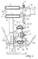
- 1 designates a machine for mounting and removing special tires 2 from their wheel rim 3, which is constituted by a floor-mounted turret 4 on which a unit 5 for coupling and turning wheels 6 fitted with special tires 2 is mounted.
- a pusher 7 which acts transversely on the beads 2a of the tires 2 and is provided with means 7a for adjusting its intervention position.
- the wheels 6 turn about a horizontal axis A which is perpendicular to the turret 4.
- the pusher 7 is constituted by two double-acting fluid-driven actuators 8 which have horizontal axes and stems 8a; the free ends of their stems 8a are rigidly coupled to a support 9 which is slidingly mounted on a guide 9a for at least one free roller 10 which has a vertical axis and is adapted to be placed in contact with the beads 2a of the tires 2.
- roller 10 can be replaced with two rollers 110 which are supported on the support 9 so as to be vertically coplanar and so that their rotation axes B (as shown in Figure 8) substantially converge towards the unit 5 for coupling and turning the wheels 6.
- the rollers 10 can be cylindrical or frustum-shaped, with the larger flat face directed towards the center of the unit 5, for mutual contact with the beads 2a of the tires 2.
- the means 7a for adjusting the intervention position of the rollers 10 (110) are constituted by a third double-acting fluid-driven actuator 11 which is mounted so as to have a vertical axis on the support 9; the rollers 10 or 110 is, or are, rigidly coupled to the free end of the stem 11 a of the actuator.
- the support 9 also supports a lever 12 which is articulated thereto and is provided with a claw 13 for lifting a flap of the bead 2a of the tire 2 when it is mounted on the coupling and rotation unit 5.
- the complementary presser 14 for the beads 2a, whose position can be adjusted through corresponding manual or automatic means 15; the complementary presser 14 is constituted, for the outer side of the wheel 6, by an additional roller 16 which is supported so that it can rotate freely with a vertical rotation axis and can be slidingly arranged on a supporting bar 17 which protrudes at right angles from the floor-mounted turret 4 and is provided with an operating handle 17a.
- rollers 18 For the inner side, there is an additional pair of rollers 18 which are freely mounted with converging axes 18a on a corresponding support 19 which is in turn mounted so that it can slide on a second bar 20 supported by the turret 4 and also provided with an operating handle 20a.
- the actuators 8 move the support 9 horizontally until the roller 10, or the pair of rollers 110, rest tangentially against the outer bead 2a of the tire 2.
- the vertical actuator 11 further arranges the rollers 10 (110) accordingly.
- the unit 5 then turns the wheel 6 and the actuators apply progressive traction until the rollers 10 (110) separate the bead 2a from the edge of the wheel rim 3 over an angular segment, pushing the bead towards the internal channel 3a of the wheel rim.
- Rotation is interrupted and an operator then acts on the lever 12 and wedges the claw 13 between the bead 2a and the edge of the wheel rim 3, raising it; at the same time, the actuators 8 and 11 move the roller 10 (or rollers 110) on the inner side of the wheel 6, placing them in contact with the corresponding upper part of the inner bead 2a.
- the unit 5 is turned again and the actuators 8 apply a transverse outward thrust together with an operator who, by acting on the handle 20a, presses the pair of rollers 18 tangentially against the lower region of the inner bead.
- the tire is placed on the unit 5 in the conventional manner; first of all, the ring 2b is fitted thereon, then the deflated tire 2 is loosely fitted thereon.
- the roller 10 By means of the actuators 8 and 11, the roller 10 (or rollers 110) are then placed against the upper part of the outer bead 2a; in a substantially opposite position, the operator, by acting on the handle 17a, places and keeps the roller 16 pressed against the outer lower part of the bead 2a; then the unit 5 is turned and the transverse pressure applied in combination by the rollers 10 (110) and 16 causes the outer bead 2a to gradually enter the channel 3a of the wheel rim 3.
- the rotation of the unit 5 is stopped, the rollers 10 (110) are returned into pressing contact with the inner bead 2a, and one proceeds in a similar manner, pushing the bead into the channel 3a, using, for the lower region of the wheel 6, the pair of rollers 18, which are kept pressed, again tangentially, against the bead 2a by the operator, who acts on the handle 20a.
- the tire 2 is inflated so as to make the beads 2a adhere to the respective sidewalls of the wheel rim 3 and then the wheel 6 is removed from the unit 5.
- the machine can also be used for mounting and removing conventional tires, taking care to repeat the above-described operations for both sides of a wheel.
- rollers 16 and 18 can be actuated not only manually but also automatically by using additional fluid-driven actuators.
Landscapes
- Engineering & Computer Science (AREA)
- Mechanical Engineering (AREA)
- Tyre Moulding (AREA)
- Tires In General (AREA)
- Workshop Equipment, Work Benches, Supports, Or Storage Means (AREA)
- Vehicle Cleaning, Maintenance, Repair, Refitting, And Outriggers (AREA)
- Automobile Manufacture Line, Endless Track Vehicle, Trailer (AREA)
- Processing And Handling Of Plastics And Other Materials For Molding In General (AREA)
- Crushing And Pulverization Processes (AREA)
Applications Claiming Priority (2)
| Application Number | Priority Date | Filing Date | Title |
|---|---|---|---|
| ITMO990015 | 1999-02-04 | ||
| IT1999MO000015A IT1310170B1 (it) | 1999-02-04 | 1999-02-04 | Macchina per il montaggio e lo smontaggio di pneumatici di tipospeciale |
Publications (3)
| Publication Number | Publication Date |
|---|---|
| EP1026017A2 EP1026017A2 (en) | 2000-08-09 |
| EP1026017A3 EP1026017A3 (en) | 2001-08-29 |
| EP1026017B1 true EP1026017B1 (en) | 2006-05-24 |
Family
ID=11386838
Family Applications (1)
| Application Number | Title | Priority Date | Filing Date |
|---|---|---|---|
| EP00101296A Expired - Lifetime EP1026017B1 (en) | 1999-02-04 | 2000-01-27 | Machine for mounting and removing special tires |
Country Status (5)
| Country | Link |
|---|---|
| US (1) | US6443206B1 (it) |
| EP (1) | EP1026017B1 (it) |
| JP (1) | JP2000225819A (it) |
| DE (1) | DE60028102T2 (it) |
| IT (1) | IT1310170B1 (it) |
Families Citing this family (12)
| Publication number | Priority date | Publication date | Assignee | Title |
|---|---|---|---|---|
| ITVR20020058A1 (it) * | 2002-05-23 | 2003-11-24 | Butler Eng & Marketing | Macchina monta-smontagomme per ruote di veicoli industriali |
| ITMO20030132A1 (it) * | 2003-05-09 | 2004-11-10 | Giuliano Srl | Macchina per il montaggio e lo smontaggio di pneumatici e cerchi di ruote per veicoli. |
| ITRE20030095A1 (it) * | 2003-10-14 | 2005-04-15 | Corghi Spa | Dispositivo stallonatore per macchine smontagomme. |
| US7343955B2 (en) | 2005-12-28 | 2008-03-18 | Hennessy Industries, Inc. | Tire changing machine |
| US7438109B2 (en) * | 2005-12-30 | 2008-10-21 | Hennessy Industries, Inc. | Tire changer |
| JP4940729B2 (ja) * | 2006-03-31 | 2012-05-30 | 株式会社ジェイテクト | 工作物の研削方法及び研削装置 |
| ITMC20060117A1 (it) * | 2006-09-11 | 2008-03-12 | Corghi Spa | Dispositivo accessorio per macchine smontagomme, atto ad agevolare lo smontaggio del pneumatico. |
| ITMI20062076A1 (it) * | 2006-10-27 | 2008-04-28 | C M L S N C Di Marco Galbiati & C | Testata di lavoro per macchina smontagonmme e relativa macchina smontagomme |
| US8333228B1 (en) | 2008-10-15 | 2012-12-18 | Hennessy Industries, Inc. | Tire changer with attached inflation cage |
| IT201600071778A1 (it) * | 2016-07-08 | 2018-01-08 | Butler Eng And Marketing S P A | Gruppo di stallonamento di una ruota gommata e/o di spinta di una porzione di un pneumatico di una ruota gommata |
| IT201600111370A1 (it) * | 2016-11-04 | 2018-05-04 | Nexion Spa | Apparato per montare e smontare uno pneumatico |
| JP6881255B2 (ja) * | 2017-11-24 | 2021-06-02 | トヨタ自動車株式会社 | 車両用シフトバイワイヤ装置 |
Family Cites Families (9)
| Publication number | Priority date | Publication date | Assignee | Title |
|---|---|---|---|---|
| BE672886A (it) * | 1965-11-26 | 1966-03-16 | ||
| DE3401476A1 (de) * | 1984-01-18 | 1985-07-25 | Gebr. Hofmann Gmbh & Co Kg Maschinenfabrik, 6100 Darmstadt | Montagevorrichtung fuer reifen |
| DE3583145D1 (de) * | 1985-09-04 | 1991-07-11 | Schenck Auto Service Geraete | Verfahren zur montage oder demontage eines fahrzeugluftreifens sowie vorrichtung zur durchfuehrung des verfahrens. |
| DE8800372U1 (de) * | 1988-01-14 | 1988-03-24 | Stahlgruber Otto Gruber GmbH & Co, 8000 MÜnchen | Reifenmontiervorrichtung |
| IT1243660B (it) * | 1990-10-22 | 1994-06-16 | Corghi Spa | Macchina smontagomme con autrocentrante reclinabile. |
| US5226465A (en) * | 1991-02-19 | 1993-07-13 | Stahlgruber Otto Gruber Gmbh & Co. | Mounting device for motor vehicle tires |
| US5758703A (en) * | 1995-10-31 | 1998-06-02 | Onodani Machine Co., Ltd. | Apparatus for mounting and removing a tire from a wheel |
| IT1287640B1 (it) * | 1996-05-03 | 1998-08-06 | Corghi Spa | Macchina per il montaggio e lo smontaggio dei pneumatici sui e dai rispettivi cerchioni |
| IT1289137B1 (it) * | 1996-10-22 | 1998-09-25 | Butler Eng & Marketing | Macchina smontagomme |
-
1999
- 1999-02-04 IT IT1999MO000015A patent/IT1310170B1/it active
-
2000
- 2000-01-27 EP EP00101296A patent/EP1026017B1/en not_active Expired - Lifetime
- 2000-01-27 DE DE60028102T patent/DE60028102T2/de not_active Expired - Fee Related
- 2000-02-02 US US09/496,726 patent/US6443206B1/en not_active Expired - Fee Related
- 2000-02-04 JP JP2000027995A patent/JP2000225819A/ja active Pending
Also Published As
| Publication number | Publication date |
|---|---|
| ITMO990015A1 (it) | 2000-08-04 |
| EP1026017A3 (en) | 2001-08-29 |
| ITMO990015A0 (it) | 1999-02-04 |
| DE60028102T2 (de) | 2006-12-07 |
| EP1026017A2 (en) | 2000-08-09 |
| IT1310170B1 (it) | 2002-02-11 |
| DE60028102D1 (de) | 2006-06-29 |
| US6443206B1 (en) | 2002-09-03 |
| JP2000225819A (ja) | 2000-08-15 |
Similar Documents
| Publication | Publication Date | Title |
|---|---|---|
| US6619362B2 (en) | Automatic tyre removal and mounting device and tyre removal machines equipped therewith | |
| EP0947360B1 (en) | Tyre removal machine and relative accessories | |
| EP1052120B1 (en) | Multipurpose station for mounting and removing conventional and special tires | |
| EP1026017B1 (en) | Machine for mounting and removing special tires | |
| EP2233325B1 (en) | Machine for fitting and removing the wheel tyres of vehicle | |
| EP2125394B1 (en) | Apparatus for tyre-changing machines | |
| US20070256794A1 (en) | Method for extracting a foam support ring from a tire | |
| EP1029717B1 (en) | Kit of removable adapters for mounting and removing special run-flat tires by using a conventional tire changing machine | |
| US7946016B2 (en) | Method and machine for removing a tyre fitted with a rigid inner run-flat ring | |
| EP2756969B1 (en) | Machine for removing/ fitting a tyre from/ on the rim of a vehicle vehicles | |
| EP0624486A1 (en) | Machine for mounting tires on wheel rims | |
| EP1270280A2 (en) | Tool for facilitating the removal and fitting of tires on wheels | |
| US5017111A (en) | Apparatus for charging a tire heating press | |
| US6401788B1 (en) | Tire changing apparatus and method | |
| EP0987130A2 (en) | Device for tyre removal machines | |
| US2898977A (en) | Tire rim removal tool | |
| JP3704370B2 (ja) | ホイールリムからタイヤビードを外すための、タイヤ取外し機械用ビード解放ユニツト | |
| EP2905153B1 (en) | Tyre-changing machine | |
| US20080251176A1 (en) | Method and unit for mounting on a rim a tire provided with a safety support | |
| AU725177B2 (en) | An apparatus for removing a tyre wall from a tyre carcass | |
| EP1529666A2 (en) | Tire changing machine implenent for fitting and removing tires of vehicle wheels |
Legal Events
| Date | Code | Title | Description |
|---|---|---|---|
| PUAI | Public reference made under article 153(3) epc to a published international application that has entered the european phase |
Free format text: ORIGINAL CODE: 0009012 |
|
| AK | Designated contracting states |
Kind code of ref document: A2 Designated state(s): AT BE CH CY DE DK ES FI FR GB GR IE IT LI LU MC NL PT SE |
|
| AX | Request for extension of the european patent |
Free format text: AL;LT;LV;MK;RO;SI |
|
| PUAL | Search report despatched |
Free format text: ORIGINAL CODE: 0009013 |
|
| AK | Designated contracting states |
Kind code of ref document: A3 Designated state(s): AT BE CH CY DE DK ES FI FR GB GR IE IT LI LU MC NL PT SE |
|
| AX | Request for extension of the european patent |
Free format text: AL;LT;LV;MK;RO;SI |
|
| RIC1 | Information provided on ipc code assigned before grant |
Free format text: 7B 60C 25/00 A, 7B 60C 25/132 B, 7B 60C 25/138 B |
|
| 17P | Request for examination filed |
Effective date: 20020130 |
|
| AKX | Designation fees paid |
Free format text: BE DE FR IT |
|
| RAP1 | Party data changed (applicant data changed or rights of an application transferred) |
Owner name: GIULIANO S.P.A. |
|
| 17Q | First examination report despatched |
Effective date: 20050323 |
|
| GRAP | Despatch of communication of intention to grant a patent |
Free format text: ORIGINAL CODE: EPIDOSNIGR1 |
|
| GRAS | Grant fee paid |
Free format text: ORIGINAL CODE: EPIDOSNIGR3 |
|
| GRAA | (expected) grant |
Free format text: ORIGINAL CODE: 0009210 |
|
| AK | Designated contracting states |
Kind code of ref document: B1 Designated state(s): BE DE FR IT |
|
| PG25 | Lapsed in a contracting state [announced via postgrant information from national office to epo] |
Ref country code: IT Free format text: LAPSE BECAUSE OF FAILURE TO SUBMIT A TRANSLATION OF THE DESCRIPTION OR TO PAY THE FEE WITHIN THE PRESCRIBED TIME-LIMIT;WARNING: LAPSES OF ITALIAN PATENTS WITH EFFECTIVE DATE BEFORE 2007 MAY HAVE OCCURRED AT ANY TIME BEFORE 2007. THE CORRECT EFFECTIVE DATE MAY BE DIFFERENT FROM THE ONE RECORDED. Effective date: 20060524 |
|
| REF | Corresponds to: |
Ref document number: 60028102 Country of ref document: DE Date of ref document: 20060629 Kind code of ref document: P |
|
| ET | Fr: translation filed | ||
| PLBE | No opposition filed within time limit |
Free format text: ORIGINAL CODE: 0009261 |
|
| STAA | Information on the status of an ep patent application or granted ep patent |
Free format text: STATUS: NO OPPOSITION FILED WITHIN TIME LIMIT |
|
| 26N | No opposition filed |
Effective date: 20070227 |
|
| PGFP | Annual fee paid to national office [announced via postgrant information from national office to epo] |
Ref country code: DE Payment date: 20090325 Year of fee payment: 10 |
|
| PGFP | Annual fee paid to national office [announced via postgrant information from national office to epo] |
Ref country code: BE Payment date: 20090212 Year of fee payment: 10 |
|
| PGFP | Annual fee paid to national office [announced via postgrant information from national office to epo] |
Ref country code: IT Payment date: 20090130 Year of fee payment: 10 |
|
| PGFP | Annual fee paid to national office [announced via postgrant information from national office to epo] |
Ref country code: FR Payment date: 20090130 Year of fee payment: 10 |
|
| BERE | Be: lapsed |
Owner name: *GIULIANO S.P.A. Effective date: 20100131 |
|
| REG | Reference to a national code |
Ref country code: FR Ref legal event code: ST Effective date: 20100930 |
|
| PG25 | Lapsed in a contracting state [announced via postgrant information from national office to epo] |
Ref country code: FR Free format text: LAPSE BECAUSE OF NON-PAYMENT OF DUE FEES Effective date: 20100201 |
|
| PG25 | Lapsed in a contracting state [announced via postgrant information from national office to epo] |
Ref country code: DE Free format text: LAPSE BECAUSE OF NON-PAYMENT OF DUE FEES Effective date: 20100803 |
|
| PG25 | Lapsed in a contracting state [announced via postgrant information from national office to epo] |
Ref country code: BE Free format text: LAPSE BECAUSE OF NON-PAYMENT OF DUE FEES Effective date: 20100131 |
|
| PG25 | Lapsed in a contracting state [announced via postgrant information from national office to epo] |
Ref country code: IT Free format text: LAPSE BECAUSE OF NON-PAYMENT OF DUE FEES Effective date: 20100127 |