EP1024635A1 - Génération d'intervalle de garde dans une transmission en modulation DMT - Google Patents
Génération d'intervalle de garde dans une transmission en modulation DMT Download PDFInfo
- Publication number
- EP1024635A1 EP1024635A1 EP00410006A EP00410006A EP1024635A1 EP 1024635 A1 EP1024635 A1 EP 1024635A1 EP 00410006 A EP00410006 A EP 00410006A EP 00410006 A EP00410006 A EP 00410006A EP 1024635 A1 EP1024635 A1 EP 1024635A1
- Authority
- EP
- European Patent Office
- Prior art keywords
- symbol
- samples
- circuit
- complex
- prefix
- Prior art date
- Legal status (The legal status is an assumption and is not a legal conclusion. Google has not performed a legal analysis and makes no representation as to the accuracy of the status listed.)
- Granted
Links
- 230000005540 biological transmission Effects 0.000 title description 7
- 125000004122 cyclic group Chemical group 0.000 claims description 22
- 238000000034 method Methods 0.000 claims description 3
- 230000010363 phase shift Effects 0.000 claims description 3
- 230000009466 transformation Effects 0.000 abstract 1
- 101150012579 ADSL gene Proteins 0.000 description 1
- 102100020775 Adenylosuccinate lyase Human genes 0.000 description 1
- 108700040193 Adenylosuccinate lyases Proteins 0.000 description 1
- 230000006870 function Effects 0.000 description 1
- 230000002123 temporal effect Effects 0.000 description 1
Images



Classifications
-
- H—ELECTRICITY
- H04—ELECTRIC COMMUNICATION TECHNIQUE
- H04L—TRANSMISSION OF DIGITAL INFORMATION, e.g. TELEGRAPHIC COMMUNICATION
- H04L27/00—Modulated-carrier systems
- H04L27/26—Systems using multi-frequency codes
- H04L27/2601—Multicarrier modulation systems
- H04L27/2602—Signal structure
- H04L27/2605—Symbol extensions, e.g. Zero Tail, Unique Word [UW]
- H04L27/2607—Cyclic extensions
-
- H—ELECTRICITY
- H04—ELECTRIC COMMUNICATION TECHNIQUE
- H04L—TRANSMISSION OF DIGITAL INFORMATION, e.g. TELEGRAPHIC COMMUNICATION
- H04L27/00—Modulated-carrier systems
- H04L27/26—Systems using multi-frequency codes
- H04L27/2601—Multicarrier modulation systems
- H04L27/2626—Arrangements specific to the transmitter only
- H04L27/2627—Modulators
- H04L27/2634—Inverse fast Fourier transform [IFFT] or inverse discrete Fourier transform [IDFT] modulators in combination with other circuits for modulation
Definitions
- the present invention relates to tone modulation discrete multiples (DMT), and more particularly the generation of cyclic prefixes in a modulation transmission DMT.
- DMT modulation is for example used by ADSL and ADSL-lite standards.
- IFFT fast inverse Fourier transform
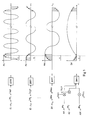
- Figure 1 illustrates the IFFT transform of a group of N complex coefficients A 1 .e j ⁇ 1 to A N .e j ⁇ N.
- Each coefficient A i .e j ⁇ i where i is between 1 and N, is associated with a respective frequency or tone f i .
- the transform of a coefficient A i .e j ⁇ i is a sequence of digital samples in the time domain forming a sinusoidal carrier section of frequency f i , of amplitude A i , and of phase ⁇ i .
- a first curve represents a section of sinusoid of amplitude A 1 , of period 1 / f 1 and of phase ⁇ 1 , obtained by IFFT transform of a coefficient A 1 .e j ⁇ 1 associated with a frequency f 1 .
- a second and a third curve represent sections of sinusoids obtained by IFFT transform of coefficients A 2 .e j ⁇ 2 and AN.e j ⁇ N respectively associated with frequencies f 2 and f N.
- An IFFT transform of the group of coefficients A i .e j ⁇ i is constituted by the sum of the sinusoidal carrier sections obtained by IFFT transform of each of the coefficients A i .e j ⁇ i for i between 1 and N, this sum being called a "symbol".
- the IFFT transform of N coefficients provides a symbol Dt composed of a succession of N complex digital samples S 1 to S N. It will be noted that the shape of the symbol D t represented is not realistic, but is intended to simplify the understanding of the present description.
- the time domain samples obtained by IFFT are converted to analog to be transmitted, for example by a telephone line.
- the analog signal of the line is converted to digital, and the samples that result are converted to complex coefficients in the frequency domain by fast Fourier transform (FFT).
- FFT fast Fourier transform
- a "prefix is inserted between each symbol cyclic "(or guard interval).
- the cyclic prefix is reproduction at the head of a symbol of the last samples of this symbol.
- FIG. 2 represents a conventional circuit 10 for introducing a cyclic prefix of ⁇ samples.
- the complex coefficients A i .e j ⁇ i for i ⁇ [1, N] are supplied to a circuit 12 of inverse Fourier transform (IFFT).
- IFFT inverse Fourier transform
- the IFFT circuit 12 produces from the group of complex coefficients a symbol D t composed of N samples S 1 to S N in the time domain.
- the symbol D t is supplied to a “first-in-first-out” (FIFO) type memory 14 and to a first input of a multiplexer 16.
- the output of the memory 14 is connected to a second input of the multiplexer 16 .
- FIFO first-in-first-out
- the circuit IFFT 12 supplies a first sample S 1 of the symbol D t , and the memory 14 is commanded in writing to store this sample and the following ones.
- Multiplexer 16 is switched to select the output of memory 14 which provides a sample of a previous symbol. This configuration of circuit 10 remains unchanged until an instant t N- ⁇ .
- the memory 14 has finished supplying the samples of the preceding symbol and it contains the samples of the current symbol D t , up to the last sample preceding the cyclic prefix.
- the IFFT circuit 12 begins to supply the samples of the prefix, which samples, designated S I to S N , continue to be stored in the memory 14.
- the multiplexer 16 is switched so that it transmits these samples S I to S N of the prefix. This configuration of circuit 10 remains unchanged until an instant t N.
- the IFFT circuit 12 is stopped, the memory 14 contains the entire current symbol D t and the prefix has just been transmitted.
- the multiplexer 16 is again switched to transmit the samples S 1 to S N supplied by the memory 14, that is to say the symbol D t .
- the IFFT circuit 12 is reactivated and it begins to provide the samples of the following symbol.
- the instant t N + ⁇ + 1 corresponds for the following symbol to the instant t 1 described above.
- circuit 10 remains unchanged until an instant 2t N when the symbol D t will have been transmitted following its cyclic prefix.
- the instant 2t N + 1 corresponds for the following symbol to the instant t N- ⁇ described above.
- a major drawback of circuit 10 is that the introduction of the cyclic prefix causes a delay t N (of N samples) in the transmission of the symbol D t . In some applications, such as telephone communications or other real-time communications, the introduction of such a delay is not acceptable.
- circuit 10 in circuit 10 according to the prior art, the number N of samples can be high, the size of the memory 14 can be important.
- An object of the present invention is to provide a cyclic prefix generation circuit which introduces a particularly low transmission delay.
- Another object of the present invention is to provide such a circuit which uses a reduced size say.
- the present invention provides a circuit for generating a cyclic prefix of a symbol composed of a sequence of samples in the time domain, said prefix being the reproduction of the last samples of the symbol at the top of the symbol, the symbol being obtained by transform Fourier inverse of complex coefficients corresponding to respective frequencies, including means for phase shifting each complex coefficient of a value proportional to its frequency, a memory for storing samples from the start of symbol, and means for copying at the end of the symbol stored samples.
- the means for shifting the complex coefficients include a connected multiplier to multiply each complex coefficient by a complex value of unit norm and proportional phase at the frequency associated with each coefficient.
- the memory is of the "first in first out” type.
- the means for copying the stored samples include a multiplexer including a first input and a second input are respectively connected to the input and output of the memory.
- the present invention further relates to a method of generation a cyclic prefix of a symbol in the field temporal, said prefix being the reproduction of the last samples of the symbol at the head of the symbol, the symbol being obtained by inverse Fourier transform of complex coefficients corresponding to respective frequencies, which includes the steps of shifting each complex coefficient by one value proportional to the frequency with which it is associated, to store the samples from the beginning of the symbol, and to copy the samples stored at the end of the symbol.
- the present invention provides for shifting so circular the samples of a symbol to which we want to add a cyclic prefix, so that the last samples composing the symbol before shift are found at the head of the symbol after shift, and thus directly form the prefix.
- we transmitting the symbol thus shifted we transmit first the prefix and then part of the symbol that just complete with the prefix to reconstitute the symbol. So, we introduces only a delay equal to the prefix in the transmission and just store only the prefix in order to be able to retransmit to complete the symbol.
- the circular offset of the symbol must correspond to the same circular offset of each of the sinusoids that make up the symbol. To do this, we multiply each coefficient complex in the frequency domain by a complex factor causing a phase shift in the time domain, corresponding at the desired circular offset.
- Figure 3 is intended to illustrate this procedure in more detail. It illustrates the transform by IFFT of a group of N complex coefficients A 1 .e j ⁇ 1 to A N .e j ⁇ N multiplied according to the present invention by shift coefficients e jK 1 ⁇ to e jK N ⁇ respectively. Multiplying a coefficient A i .e j ⁇ i by a complex coefficient e j ⁇ amounts to modifying the phase ⁇ i by a value ⁇ .
- the phase shift ⁇ causes a circular shift of the corresponding sinusoid section by a value ⁇ / 2 ⁇ f i , where fi is the frequency of the sinusoid section. This offset is therefore not constant, but a function of the frequency f i .
- the N complex coefficients A 1 .e j ⁇ 1 to A N .e J ⁇ N are phase-shifted so that the corresponding sinusoid sections are all shifted circularly by the same value, or by the same number T of samples.
- each coefficient A i .e j ⁇ i is multiplied by a coefficient of the form e jK i ⁇ where K i is 2 ⁇ f i .
- the symbol D t 'formed by the sum of the sinusoid sections corresponding to the coefficients A i .e j ⁇ ie jK i ⁇ , where i varies from 1 to N corresponds to the preceding symbol D t having undergone a circular shift of ⁇ samples .
- the coefficients e jK i ⁇ are predetermined, and they can for example be stored in a read only memory.
- FIG. 4 represents an embodiment of circuit 20 for generating a cyclic prefix according to the present invention.
- This circuit is similar to that of FIG. 2, and the same references designate the same elements.
- the complex coefficients A i .e j ⁇ i for i ⁇ [1, N] are supplied to the IFFT circuit 12 via a complex multiplier 22 of which a second input receives in correspondence the N coefficients e jK i ⁇ above.
- the symbol D t 'provided by the circuit IFFT in FIG. 4 corresponds to the symbol D t in FIG. 2 having undergone a circular shift of ⁇ samples.
- the samples S 1 'to S J ' of the first ⁇ moments of the symbol D t ' are the samples S I to S N of the last ⁇ moments of the symbol D t .
- the samples S 1 'to S J ' of the symbol D t ' constitute the cyclic prefix of the symbol D t , and the following samples of the symbol D t ' constitute the first T- ⁇ samples of the symbol D t .
- the circuit IFFT 12 supplies the first sample S 1 'of the symbol D t ', and the memory 24 is commanded in writing to store the samples produced by the circuit IFFT.
- the multiplexer 16 is switched to select the output of the IFFT circuit 12. This configuration of the circuit 10 remains unchanged until an instant t ⁇ ; it makes it possible to store the samples S 1 'to S J ' in the memory 24 and to produce at the output of the multiplexer 16 the cyclic prefix, formed by the samples S 1 'to S J '.
- the memory 24, which has just stored the samples S 1 'to S J ', is inactivated.
- the position of the multiplexer 16 is not changed, and this configuration of the circuit 10 is maintained until an instant t N.
- the multiplexer 16 produces in this interval the samples S J + 1 ' to S N ' of the symbol D t ', which correspond to the samples S 1 to S I described above.
- the IFFT circuit 12 is stopped, the memory 24 is read-controlled to produce the first sample S 1 ′ which it contains, and the multiplexer 16 is switched to select the output of the memory 24 This configuration of circuit 10 remains unchanged until an instant t N + ⁇ . In this interval, the multiplexer 16 successively produces the samples S 1 'to S J ' read from the memory 24, which correspond to the aforementioned samples S I + 1 to S N.
- the IFFT circuit 12 is reactivated to supply the samples of the following symbol and the cycle which has just been described begins again as at time t 1 .
- the present invention makes it possible to generate the cyclic prefix of a symbol by delaying the symbol only for the duration ⁇ of the prefix. This represents a time saving of t N- ⁇ compared to the prior art, which is particularly advantageous in the case of real-time transmissions.
- the memory 24 used according to the present invention is small, because it is only used to store the samples making up the prefix.
Landscapes
- Engineering & Computer Science (AREA)
- Computer Networks & Wireless Communication (AREA)
- Signal Processing (AREA)
- Physics & Mathematics (AREA)
- Discrete Mathematics (AREA)
- General Physics & Mathematics (AREA)
- Mathematical Physics (AREA)
- Digital Transmission Methods That Use Modulated Carrier Waves (AREA)
- Complex Calculations (AREA)
Abstract
Description
Claims (5)
- Circuit de génération d'un préfixe cyclique d'un symbole composé d'une séquence d'échantillons dans le domaine temporel, ledit préfixe étant la reproduction des derniers échantillons du symbole en tête du symbole, le symbole étant obtenu par transformée de Fourier inverse de coefficients complexes correspondant à des fréquences respectives, caractérisé en ce qu'il comprend :des moyens (22) pour déphaser chaque coefficient complexe d'une valeur proportionnelle à sa fréquence de manière que lesdits derniers échantillons du symbole soient décalés en tête du symbole selon une permutation circulaire,une dire (24) pour iriser lesdits échantillons décalés, etdes moyens (16) pour recopier à la fin du symbole les échantillons mémorisés.
- Circuit de génération d'un préfixe cyclique selon la revendication 1, caractérisé en ce que les moyens pour déphaser les coefficients complexes comprennent un multiplieur (22) connecté pour multiplier chaque coefficient complexe par une valeur complexe de norme unitaire et de phase proportionnelle à la fréquence associée à chaque coefficient.
- Circuit de génération d'un préfixe cyclique selon la revendication 1, caractérisé en ce que la mémoire (24) est de type "premier entré premier sorti" (FIFO).
- Circuit de génération d'un préfixe cyclique selon la revendication 1, caractérisé en ce que les moyens pour recopier les échantillons mémorisés comprennent un multiplexeur (16) dont une première entrée et une deuxième entrée sont respectivement connectées à l'entrée et à la sortie de la mémoire.
- Procédé de génération d'un préfixe cyclique d'un symbole dans le domaine temporel, ledit préfixe étant la reproduction des derniers échantillons du symbole en tête du symbole, le symbole étant obtenu par transformée de Fourier inverse de coefficients complexes correspondant à des fréquences respectives, caractérisé en ce qu'il comprend les étapes consistant à :déphaser chaque coefficient complexe d'une valeur proportionnelle à la fréquence à laquelle il est associé,stocker les échantillons du début du symbole, etrecopier les échantillons mémorisés à la fin du symbole.
Applications Claiming Priority (2)
| Application Number | Priority Date | Filing Date | Title |
|---|---|---|---|
| FR9901062A FR2788907B1 (fr) | 1999-01-27 | 1999-01-27 | Generation d'intervalle de garde dans une transmission en modulation dmt |
| FR9901062 | 1999-01-27 |
Publications (2)
| Publication Number | Publication Date |
|---|---|
| EP1024635A1 true EP1024635A1 (fr) | 2000-08-02 |
| EP1024635B1 EP1024635B1 (fr) | 2003-05-02 |
Family
ID=9541411
Family Applications (1)
| Application Number | Title | Priority Date | Filing Date |
|---|---|---|---|
| EP00410006A Expired - Lifetime EP1024635B1 (fr) | 1999-01-27 | 2000-01-25 | Génération d'intervalle de garde dans une transmission en modulation DMT |
Country Status (5)
| Country | Link |
|---|---|
| US (1) | US7633851B2 (fr) |
| EP (1) | EP1024635B1 (fr) |
| JP (1) | JP2000224138A (fr) |
| DE (1) | DE60002371T2 (fr) |
| FR (1) | FR2788907B1 (fr) |
Cited By (2)
| Publication number | Priority date | Publication date | Assignee | Title |
|---|---|---|---|---|
| WO2005022794A2 (fr) | 2003-08-27 | 2005-03-10 | Sasken Communication Technologies Limited | Combinaison d'une transformation de fourier rapide inverse et du traitement des intervalles de protection pour la mise en oeuvre efficace de systemes a multiplexage par repartition orthogonale de la frequence |
| WO2005099211A1 (fr) * | 2004-03-31 | 2005-10-20 | Intel Corporation | Systeme ofdm avec rotation de phase de sous porteuse |
Families Citing this family (10)
| Publication number | Priority date | Publication date | Assignee | Title |
|---|---|---|---|---|
| KR100353598B1 (ko) * | 2000-10-05 | 2002-09-27 | 전자부품연구원 | 지퍼 방식의 브이디에스엘 시스템 |
| EP1782594A1 (fr) * | 2004-08-20 | 2007-05-09 | NTT DoCoMo, Inc. | Appareil et procede de reduction de derive de phase |
| US8031586B2 (en) | 2007-08-15 | 2011-10-04 | Nokia Corporation | Method and apparatus for transmitter timing adjustment |
| KR100884385B1 (ko) * | 2007-08-31 | 2009-02-17 | 한국전자통신연구원 | 신호 송신 장치 및 그 방법, 이를 위한 역고속 푸리에 변환장치 |
| US8059751B2 (en) | 2008-02-08 | 2011-11-15 | Nokia Corporation | Frequency dependent phase rotation prior to mapping in an OFDM transmitter |
| US8605568B2 (en) | 2009-04-14 | 2013-12-10 | Texas Instruments Incorporated | PHY layer options for body area network (BAN) devices |
| US11785482B1 (en) | 2019-11-26 | 2023-10-10 | ZaiNar, Inc. | Method for identifying and diagnosing failures in pairwise time synchronization and frequency calibration in a mesh network |
| US11863298B1 (en) | 2019-11-26 | 2024-01-02 | ZaiNar, Inc. | Method for identifying and diagnosing failures in pairwise time synchronization and frequency calibration in a mesh network |
| EP4182904A4 (fr) * | 2020-07-17 | 2024-01-17 | Zainar, Inc. | Systèmes et procédés de localisation à base de phase multiporteuse |
| EP4232839A4 (fr) | 2020-10-26 | 2024-06-26 | Zainar, Inc. | Procédé hybride de télémétrie basée sur le temps d'arrivée |
Citations (4)
| Publication number | Priority date | Publication date | Assignee | Title |
|---|---|---|---|---|
| DE4425713C1 (de) * | 1994-07-20 | 1995-04-20 | Inst Rundfunktechnik Gmbh | Verfahren zur Vielträger Modulation und Demodulation von digital codierten Daten |
| EP0682426A2 (fr) * | 1994-05-09 | 1995-11-15 | Victor Company Of Japan, Limited | Emetteur et récepteur pour MDFO |
| EP0719004A2 (fr) * | 1994-12-20 | 1996-06-26 | Matsushita Electric Industrial Co., Ltd. | Système MDFO avec protection additionelle contre des effets résultant des voies multiples |
| EP0820171A1 (fr) * | 1996-07-15 | 1998-01-21 | Alcatel Bell N.V. | Emeteur ou récepteur pour porteurs multiples avec rotateurs de phase |
Family Cites Families (17)
| Publication number | Priority date | Publication date | Assignee | Title |
|---|---|---|---|---|
| US4112430A (en) * | 1977-06-01 | 1978-09-05 | The United States Of America As Represented By The Secretary Of The Navy | Beamformer for wideband signals |
| GB9218874D0 (en) * | 1992-09-07 | 1992-10-21 | British Broadcasting Corp | Improvements relating to the transmission of frequency division multiplex signals |
| CA2115118A1 (fr) * | 1993-02-08 | 1994-08-09 | Arie Geert Cornelis Koppelaar | Methode de transmission de flots de donnees et emetteur et recepteur connexes |
| JPH0746218A (ja) * | 1993-07-28 | 1995-02-14 | Sony Corp | ディジタル復調装置 |
| US5519731A (en) * | 1994-04-14 | 1996-05-21 | Amati Communications Corporation | ADSL compatible discrete multi-tone apparatus for mitigation of T1 noise |
| US5657313A (en) * | 1994-05-09 | 1997-08-12 | Victor Company Of Japan, Ltd. | Signal transmitting apparatus and signal receiving apparatus using orthogonal frequency division multiplexing |
| EP0725509A1 (fr) * | 1995-01-31 | 1996-08-07 | ALCATEL BELL Naamloze Vennootschap | Système de transmission spécifiquement dédicacé pour accès multiple par répartition en fréquences, émetteur et récepteur utilisés dans un tel système de transmission |
| US5822323A (en) * | 1995-09-29 | 1998-10-13 | Victor Company Of Japan, Ltd. | Frequency division multiplexed signal generating apparatus and related decoding apparatus |
| US5729577A (en) * | 1996-05-21 | 1998-03-17 | Motorola, Inc. | Signal processor with improved efficiency |
| US6285654B1 (en) * | 1996-08-22 | 2001-09-04 | Tellabs Operations, Inc. | Apparatus and method for symbol alignment in a multi-point OFDM or DMT digital communications system |
| US6148024A (en) * | 1997-03-04 | 2000-11-14 | At&T Corporation | FFT-based multitone DPSK modem |
| US6058101A (en) * | 1997-06-11 | 2000-05-02 | Industrial Technology Research Institute | Synchronization method and system for a digital receiver |
| JPH1117643A (ja) * | 1997-06-19 | 1999-01-22 | Hitachi Denshi Ltd | Ofdm変調器 |
| US5991289A (en) * | 1997-08-05 | 1999-11-23 | Industrial Technology Research Institute | Synchronization method and apparatus for guard interval-based OFDM signals |
| JPH1168696A (ja) * | 1997-08-19 | 1999-03-09 | Sony Corp | 通信方法及び送信装置及び受信装置並びにセルラー無線通信システム |
| US6546055B1 (en) * | 1998-01-12 | 2003-04-08 | The Board Of Trustees Of The Leland Stanford Junior University | Carrier offset determination for RF signals having a cyclic prefix |
| SE522440C2 (sv) * | 2000-01-31 | 2004-02-10 | Ericsson Telefon Ab L M | Omvandlare |
-
1999
- 1999-01-27 FR FR9901062A patent/FR2788907B1/fr not_active Expired - Fee Related
-
2000
- 2000-01-25 EP EP00410006A patent/EP1024635B1/fr not_active Expired - Lifetime
- 2000-01-25 DE DE60002371T patent/DE60002371T2/de not_active Expired - Lifetime
- 2000-01-26 JP JP2000017221A patent/JP2000224138A/ja not_active Abandoned
-
2004
- 2004-01-21 US US10/761,708 patent/US7633851B2/en not_active Expired - Lifetime
Patent Citations (4)
| Publication number | Priority date | Publication date | Assignee | Title |
|---|---|---|---|---|
| EP0682426A2 (fr) * | 1994-05-09 | 1995-11-15 | Victor Company Of Japan, Limited | Emetteur et récepteur pour MDFO |
| DE4425713C1 (de) * | 1994-07-20 | 1995-04-20 | Inst Rundfunktechnik Gmbh | Verfahren zur Vielträger Modulation und Demodulation von digital codierten Daten |
| EP0719004A2 (fr) * | 1994-12-20 | 1996-06-26 | Matsushita Electric Industrial Co., Ltd. | Système MDFO avec protection additionelle contre des effets résultant des voies multiples |
| EP0820171A1 (fr) * | 1996-07-15 | 1998-01-21 | Alcatel Bell N.V. | Emeteur ou récepteur pour porteurs multiples avec rotateurs de phase |
Cited By (4)
| Publication number | Priority date | Publication date | Assignee | Title |
|---|---|---|---|---|
| WO2005022794A2 (fr) | 2003-08-27 | 2005-03-10 | Sasken Communication Technologies Limited | Combinaison d'une transformation de fourier rapide inverse et du traitement des intervalles de protection pour la mise en oeuvre efficace de systemes a multiplexage par repartition orthogonale de la frequence |
| EP1665594A4 (fr) * | 2003-08-27 | 2009-04-29 | Sasken Comm Technologies Ltd | Combinaison d'une transformation de fourier rapide inverse et du traitement des intervalles de protection pour la mise en oeuvre efficace de systemes a multiplexage par repartition orthogonale de la frequence |
| WO2005099211A1 (fr) * | 2004-03-31 | 2005-10-20 | Intel Corporation | Systeme ofdm avec rotation de phase de sous porteuse |
| US7447268B2 (en) | 2004-03-31 | 2008-11-04 | Intel Corporation | OFDM system with per subcarrier phase rotation |
Also Published As
| Publication number | Publication date |
|---|---|
| DE60002371D1 (de) | 2003-06-05 |
| FR2788907A1 (fr) | 2000-07-28 |
| JP2000224138A (ja) | 2000-08-11 |
| FR2788907B1 (fr) | 2001-04-13 |
| EP1024635B1 (fr) | 2003-05-02 |
| US20040151110A1 (en) | 2004-08-05 |
| US7633851B2 (en) | 2009-12-15 |
| DE60002371T2 (de) | 2004-02-26 |
Similar Documents
| Publication | Publication Date | Title |
|---|---|---|
| EP1024635B1 (fr) | Génération d'intervalle de garde dans une transmission en modulation DMT | |
| EP1505787A2 (fr) | Préambule de synchronisation pour un système MDFO (OFDM) | |
| FR2709629A1 (fr) | Processeur de signaux en bande de base modulés en amplitude à niveaux multiples superposés. | |
| EP2115980A2 (fr) | Procédé de traitement de symboles dans une communication bidirectionnelle par retournement temporel, et entité communicante pour sa mise en oeuvre | |
| FR2672139A1 (fr) | Generateur de base de temps rapide. | |
| FR2473824A1 (fr) | Procede de commutation entre les recepteurs et les correlateurs d'un systeme de communication et appareil de reception-correlation pour la mise en oeuvre de ce procede | |
| FR2600478A1 (fr) | Procede et dispositif pour geler une image de television | |
| FR2739238A1 (fr) | Codage acoustique asynchrone a base de groupes de frequences envoyees simultanement | |
| EP1878185A1 (fr) | Procédé de codage d'un signal multiporteuse de type ofdm/oqam utilisant des symboles à valeurs complexes, signal, dispositifs et programmes d'ordinateur correspondants | |
| JP2019526202A (ja) | OvXDMシステムに適用される一種類の変調方法、装置及びOvXDMシステム | |
| FR3026907A1 (fr) | Procede d'emission d'un signal multi-porteuses, procede de reception, dispositifs, et programmes d'ordinateurs associes | |
| US20080256154A1 (en) | Method and Apparatus for Synthesizing a User Defined Pre-Emphasized Arbitrary Waveform for High Speed Serial Data Technologies | |
| US20080240318A1 (en) | Recovering precoded data using a Mueller-Muller recovery mechanism | |
| EP1005748B1 (fr) | Modulation multiporteuse employant des fonctions prototypes ponderees | |
| FR2672454A1 (fr) | Procede de demodulation coherente pour modulation a deplacement de phase et dispositif de mise en óoeuvre de ce procede. | |
| FR2809575A1 (fr) | Recepteur, procede de reception, et milieu d'enregistrement qui enregistre un programme pour recevoir des signaux de donnees | |
| JP2003348041A (ja) | Ofdm信号の送信装置 | |
| FR2495408A1 (fr) | Dispositif de decodage d'une information numerique exprimee selon un code a inversion de marque | |
| FR2798025A1 (fr) | Appareil de reception pour decoder un signal serie en signal d'informations et systeme de communication muni de l'appareil de reception | |
| JP2001136150A (ja) | 制御信号を用いるofdm信号の伝送システムならびにこれに関する装置及び方法 | |
| JP4106612B2 (ja) | 直接拡散スペクトル拡散信号の送信装置 | |
| RU2010129922A (ru) | Способ и приемный модуль для синхронизации пакетно-ориентированного принимаемого тонального сигнала с генерируемым тональным сигналом | |
| JP2004320088A (ja) | スペクトル拡散変調信号発生方法 | |
| KR100766571B1 (ko) | 오에프디엠(직교주파수분할다중화) 신호 생성 방법 및 장치 | |
| FR3105903A1 (fr) | génération d’une séquence d’apprentissage composée d’une pluralité de symboles OFDM |
Legal Events
| Date | Code | Title | Description |
|---|---|---|---|
| PUAI | Public reference made under article 153(3) epc to a published international application that has entered the european phase |
Free format text: ORIGINAL CODE: 0009012 |
|
| AK | Designated contracting states |
Kind code of ref document: A1 Designated state(s): DE FR GB IT |
|
| AX | Request for extension of the european patent |
Free format text: AL;LT;LV;MK;RO;SI |
|
| 17P | Request for examination filed |
Effective date: 20010118 |
|
| AKX | Designation fees paid |
Free format text: DE FR GB IT |
|
| RAP1 | Party data changed (applicant data changed or rights of an application transferred) |
Owner name: STMICROELECTRONICS S.A. |
|
| 17Q | First examination report despatched |
Effective date: 20011207 |
|
| GRAG | Despatch of communication of intention to grant |
Free format text: ORIGINAL CODE: EPIDOS AGRA |
|
| GRAG | Despatch of communication of intention to grant |
Free format text: ORIGINAL CODE: EPIDOS AGRA |
|
| GRAH | Despatch of communication of intention to grant a patent |
Free format text: ORIGINAL CODE: EPIDOS IGRA |
|
| GRAH | Despatch of communication of intention to grant a patent |
Free format text: ORIGINAL CODE: EPIDOS IGRA |
|
| GRAA | (expected) grant |
Free format text: ORIGINAL CODE: 0009210 |
|
| AK | Designated contracting states |
Designated state(s): DE FR GB IT |
|
| PG25 | Lapsed in a contracting state [announced via postgrant information from national office to epo] |
Ref country code: IT Free format text: LAPSE BECAUSE OF FAILURE TO SUBMIT A TRANSLATION OF THE DESCRIPTION OR TO PAY THE FEE WITHIN THE PRESCRIBED TIME-LIMIT;WARNING: LAPSES OF ITALIAN PATENTS WITH EFFECTIVE DATE BEFORE 2007 MAY HAVE OCCURRED AT ANY TIME BEFORE 2007. THE CORRECT EFFECTIVE DATE MAY BE DIFFERENT FROM THE ONE RECORDED. Effective date: 20030502 |
|
| REG | Reference to a national code |
Ref country code: GB Ref legal event code: FG4D Free format text: NOT ENGLISH |
|
| REF | Corresponds to: |
Ref document number: 60002371 Country of ref document: DE Date of ref document: 20030605 Kind code of ref document: P |
|
| GBT | Gb: translation of ep patent filed (gb section 77(6)(a)/1977) |
Effective date: 20030806 |
|
| PLBE | No opposition filed within time limit |
Free format text: ORIGINAL CODE: 0009261 |
|
| STAA | Information on the status of an ep patent application or granted ep patent |
Free format text: STATUS: NO OPPOSITION FILED WITHIN TIME LIMIT |
|
| 26N | No opposition filed |
Effective date: 20040203 |
|
| REG | Reference to a national code |
Ref country code: FR Ref legal event code: PLFP Year of fee payment: 17 |
|
| REG | Reference to a national code |
Ref country code: FR Ref legal event code: PLFP Year of fee payment: 18 |
|
| REG | Reference to a national code |
Ref country code: FR Ref legal event code: PLFP Year of fee payment: 19 |
|
| PGFP | Annual fee paid to national office [announced via postgrant information from national office to epo] |
Ref country code: FR Payment date: 20181220 Year of fee payment: 20 Ref country code: GB Payment date: 20181219 Year of fee payment: 20 |
|
| PGFP | Annual fee paid to national office [announced via postgrant information from national office to epo] |
Ref country code: DE Payment date: 20181218 Year of fee payment: 20 |
|
| REG | Reference to a national code |
Ref country code: DE Ref legal event code: R071 Ref document number: 60002371 Country of ref document: DE |
|
| REG | Reference to a national code |
Ref country code: GB Ref legal event code: PE20 Expiry date: 20200124 |
|
| PG25 | Lapsed in a contracting state [announced via postgrant information from national office to epo] |
Ref country code: GB Free format text: LAPSE BECAUSE OF EXPIRATION OF PROTECTION Effective date: 20200124 |