EP1024458A1 - Bild-zeichnungs-vorrichtung, bild-zeichnungs-verfahren, und ausstattungs-medium - Google Patents
Bild-zeichnungs-vorrichtung, bild-zeichnungs-verfahren, und ausstattungs-medium Download PDFInfo
- Publication number
- EP1024458A1 EP1024458A1 EP99912079A EP99912079A EP1024458A1 EP 1024458 A1 EP1024458 A1 EP 1024458A1 EP 99912079 A EP99912079 A EP 99912079A EP 99912079 A EP99912079 A EP 99912079A EP 1024458 A1 EP1024458 A1 EP 1024458A1
- Authority
- EP
- European Patent Office
- Prior art keywords
- pixel data
- image
- overwriting
- value
- unit graphic
- Prior art date
- Legal status (The legal status is an assumption and is not a legal conclusion. Google has not performed a legal analysis and makes no representation as to the accuracy of the status listed.)
- Granted
Links
Images


Classifications
-
- G—PHYSICS
- G06—COMPUTING OR CALCULATING; COUNTING
- G06T—IMAGE DATA PROCESSING OR GENERATION, IN GENERAL
- G06T15/00—3D [Three Dimensional] image rendering
- G06T15/10—Geometric effects
-
- G06T11/10—
-
- G—PHYSICS
- G06—COMPUTING OR CALCULATING; COUNTING
- G06T—IMAGE DATA PROCESSING OR GENERATION, IN GENERAL
- G06T17/00—Three dimensional [3D] modelling, e.g. data description of 3D objects
-
- G—PHYSICS
- G06—COMPUTING OR CALCULATING; COUNTING
- G06T—IMAGE DATA PROCESSING OR GENERATION, IN GENERAL
- G06T5/00—Image enhancement or restoration
-
- A—HUMAN NECESSITIES
- A63—SPORTS; GAMES; AMUSEMENTS
- A63F—CARD, BOARD, OR ROULETTE GAMES; INDOOR GAMES USING SMALL MOVING PLAYING BODIES; VIDEO GAMES; GAMES NOT OTHERWISE PROVIDED FOR
- A63F2300/00—Features of games using an electronically generated display having two or more dimensions, e.g. on a television screen, showing representations related to the game
- A63F2300/20—Features of games using an electronically generated display having two or more dimensions, e.g. on a television screen, showing representations related to the game characterised by details of the game platform
- A63F2300/203—Image generating hardware
Definitions
- the present invention relates to a drawing device and drawing method, as well as a distribution medium, and more specifically, it concerns a drawing device and drawing method, and a distribution medium, that will make it possible to display images of high picture quality on, for example, three-dimensional graphic computers, which are image devices that employ a computer, or on special effects devices (effectors), video game machines, or the like.
- the display of a three-dimensional image is accomplished by performing coordinate transformations on the data of the polygons that comprise it, performing geometrical processing such as clipping and lighting, and performing perspective and projective transformations on the data obtained from such processing, thus taking data in three-dimensional space and turning it into pixel data in a two-dimensional plane, then drawing it.
- geometrical processing such as clipping and lighting
- perspective and projective transformations on the data obtained from such processing, thus taking data in three-dimensional space and turning it into pixel data in a two-dimensional plane, then drawing it.
- the position of a polygon which until then was expressed by floating point or fixed point, is converted to integers corresponding to the pixels in fixed positions on the screen. This results in aliasing and "jaggy" staircase-like edges, creating the problem that the picture quality is inferior to that of an image taken with a video camera.
- aliasing is not limited to images; when a signal is sampled at a finite number of points, it is the sampling error that occurs due to the fact that the number of sampling points is too small.
- One method for reducing the degradation of picture quality caused by aliasing is to virtually divide each pixel into smaller units called subpixels, and after ray tracing or some other calculation is done in these subpixel units, the results of the calculation are averaged to the nearest pixel unit, but ray tracing computation takes considerable time, and despite the speedup in processors, memory, and other hardware, at the present time it is impossible to do such ray tracing computation in real time for moving images. That is, a moving image generally consists of about 20-30 frames per second, but at present it is impossible with reasonably priced hardware to perform ray tracing computations 20-30 times a second in subpixel units.
- Another method is to perform antialiasing (reducing the degradation in picture quality that is caused by aliasing) by generating a high-resolution image and filtering it to reduce the number of pixels, but displaying moving images by this method requires a fast, high-capacity frame buffer or Z buffer to store the high-resolution images, which makes the equipment big and expensive.
- Another method to carry out antialiasing is a technique known as ⁇ blending, in which, if for example a certain graphic form is to be displayed, the proportion of the pixel that the graphic form occupies is determined, and it graphic form and background are ⁇ -blended based on this proportion.
- This method is used for the edges of graphic forms, but it is not effective for the flickering of textures put onto graphic forms or for the aliasing that occurs where three-dimensional shapes cross each other (intersection lines) (for example, if one sphere sinks into another, the part where the two spheres intersect each other).
- the drawing device as described in Claim 1 comprises a shift amount setting means for setting multiple shift amounts for shifting, with a precision finer than one pixel, a drawing position when pixel data is to be drawn in a pixel data memory means, and, a drawing means in the pixel data memory means, for overwriting the image by drawing the pixel data in each position corresponding to the multiple shift amounts set by the shift amount setting means.
- the drawing method as described in Claim 43 comprises a shift amount setting step of setting multiple shift amounts for shifting, with a precision finer than one pixel, the drawing position when the pixel data is to be drawn in the pixel data memory means of the drawing device, and a drawing step of overwriting the image by drawing the pixel data to each position of the pixel data memory means corresponding to the multiple shift amounts.
- the distribution medium as described in Claim 75 provides a computer program that has a shift amount setting step that sets multiple shift amounts for shifting, with a precision finer than one pixel, the drawing position when the pixel data is to be drawn to memory, and a drawing step that overwrites the image by drawing the pixel data to each position of the memory corresponding to the multiple shift amounts.
- the shift amount setting means sets multiple shift amounts for shifting, with a precision finer than one pixel, the drawing position when the pixel data is to be drawn in the pixel data memory means, and the drawing means, in the pixel data memory means, overwrites the image by drawing the pixel data in each position corresponding to the multiple shift amounts set by the shift amount setting means.
- multiple shift amounts are set for shifting, with a precision finer than one pixel, the drawing position when the pixel data is to be drawn in the pixel data memory means, and the image is overwritten by drawing the pixel data to each position of the pixel data memory means corresponding to the multiple shift amounts.
- a computer program for causing the computer to set multiple shift amounts for shifting, with a precision finer than one pixel, the drawing position when the pixel data is to be drawn to memory, and to carry out the processing to overwrite the image by drawing the pixel data to each position of the memory corresponding to the multiple shift amounts.
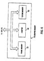
- the drawing device as described in Claim 1 includes a pixel data memory means that stores pixel data to be output to a two-dimensional output device that outputs the image (for example, a frame buffer 141 in Figure 6), a shift amount setting means that sets multiple shift amounts for shifting, with a precision finer than one pixel, the drawing position when the pixel data is to be drawn in the pixel data memory means (for example, a program processing step S6 in Figure 18), and a drawing means in the pixel data memory means that overwrites the image by drawing the pixel data in each position corresponding to the multiple shift amounts set by the shift amount setting means (for example, a program processing step S14 in Figure 18).
- the drawing device as described in Claims 3, 14, 25 and 35 further includes a count determination means that determines the number of overwriting times the drawing means shall overwrite the image (for example, a program processing step S5 in Figure 18).
- the drawing device as described in Claims 4, 15, 26 and 36 may further include an estimation means that estimates the drawing time needed for drawing one screenful of the pixel data to the pixel data memory means (for example, a program processing step S4 in Figure 18), and the count determination means determines the number of overwriting times based on the drawing time estimated by the estimation means.
- an estimation means that estimates the drawing time needed for drawing one screenful of the pixel data to the pixel data memory means (for example, a program processing step S4 in Figure 18), and the count determination means determines the number of overwriting times based on the drawing time estimated by the estimation means.
- the drawing device as described in Claims 6, 17, 28 and 38 if the image is a moving image, further comprises a correction means that corrects the shift amounts based on the movement of the moving image (for example, a program processing step S10 in Figure 18).
- the drawing device as described in Claims 8 and 19, if the image is a three-dimensional image, a sorting means is provided that sorts the unit graphic forms into the order of their depth direction (for example, a program processing step S7 in Figure 18), and the drawing means draws the unit graphic forms in order, beginning with those near the viewpoint.
- a sorting means is provided that sorts the unit graphic forms into the order of their depth direction (for example, a program processing step S7 in Figure 18), and the drawing means draws the unit graphic forms in order, beginning with those near the viewpoint.
- the drawing device as described in Claim 12 may further comprise an operation means that is operated when a prescribed input is given (for example, operation device 17 in Figure 1), an arithmetic operation means that reads in data recorded in a storage medium and performs the prescribed arithmetic operations using this data, based on input from the operation means (for example, main CPU 111 in Figure 5), and a pixel data generation means for example GPU, that determines the pixel data based on the results of the arithmetic operation by the arithmetic operation means (for example, GPU 115 in Figure 5).
- an operation means that is operated when a prescribed input is given
- an arithmetic operation means that reads in data recorded in a storage medium and performs the prescribed arithmetic operations using this data, based on input from the operation means (for example, main CPU 111 in Figure 5)
- a pixel data generation means for example GPU, that determines the pixel data based on the results of the arithmetic operation by the arithmetic operation
- a conversion means that, in accordance with the viewpoint, converts the unit graphic forms that constitute the three-dimensional image to ones in the coordinate system of the two-dimensional output device (for example, main CPU 111 in Figure 5), a sorting means that sorts the unit graphic forms converted by the conversion means into the order of their depth direction (for example, a program processing step S7 in Figure 18) and a depth memory means that records the values that represent the position of the unit graphic forms in the depth direction (for example, Z buffer 142 in Figure 6), and using the depth memory means, the drawing means draws the unit graphic forms in order, beginning with those near the viewpoint.
- the drawing device as described in Claim 33, if the image is a three-dimensional image defined by a combination of unit graphic forms, it further, comprises an operation means that is operated when a prescribed input is given (for example, operation device 17 in Figure 1), an arithmetic operation means that reads in data recorded in a storage medium and performs the prescribed arithmetic operations using this data, based on input from the operation means (for example, main CPU 111 in Figure 5), a conversion means that converts the unit graphic forms obtained as a result of calculation by the arithmetic operation means to ones in the coordinate system of the two-dimensional output device, a sorting means that sorts the unit graphic forms converted by the conversion means into the order of their depth direction (for example, a program processing step S7 in Figure 18), and a depth memory means that records the values that represent the position of the unit graphic forms in the depth direction (for example, Z buffer 142 in Figure 6), and using the depth memory means, the drawing means draws the unit graphic forms in order, beginning with those near the viewpoint.
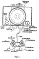
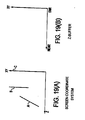
- Figure 1 is a top view showing an embodiment of a video game machine to which this invention applies.
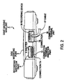
- Figure 2 is a front view of it (the view seen from below in Figure 1)
- Figure 3 is a side view of it from the right (the side view seen facing it from the right in Figure 1).
- the video game machine comprises a game machine main unit 2, an operation device (operation means) 17, which has a roughly rectangular connection terminal unit 26 that is connected with the game machine main unit 2, and a recording device 38, which is likewise connected with the game machine main unit 2.
- Game machine main unit 2 may be formed in roughly rectangular shape and has positioned in its center a disk mounting unit 3 on which one mounts a game recording medium on which are recorded computer programs (including programs for rendering (drawing) processing, which will be described later) and data for playing games.
- CD-ROM Compact Disk-Read Only Memory
- the game recording media are not limited to a disk.
- connections 7(A) and 7(B) On the left side of the disk mounting unit 3 are a reset switch 4, which is operated when the game is to be reset, and a power switch 5, which is operated when the power is to be turned on or off, and on its right side is a disk operation switch 6, which is operated when the disk mounting unit 3 is to be opened or closed.
- connections 7(A) and 7(B) On the front of the game machine main unit 2 are connections 7(A) and 7(B), by which the operation device 17 and recording device 38 can be connected as a set.
- connections 7(A) and 7(B) are provided to allow two sets of the operation device 17 and recording device 38 to be connected.
- connections 7(A) and 7(B) are provided to allow two sets of the operation device 17 and recording device 38 to be connected.
- a large number of operation devices and recording devices can be connected by attaching to connection 7(A) or 7(B)
- connections 7(A) and 7(B) have a two-stage structure, having on the upper stage a recording insertion part 8 that is connected with recording device 38, and having on the lower stage a connection terminal insertion part 12 that connects with connection terminal part 26 of operation device 17.
- the insertion hole of recording insertion part 8 has a horizontally oblong shape, and the corners on both ends of its lower side are rounder than the corners on both ends of its upper side, thus forming a structure that makes it impossible to insert the recording device 38 upside-down.
- Recording insertion part 8 also has a shutter 9 that protects the internal connection terminal (not shown) by which the electrical connection is made.
- Shutter 9 is attached so as to be urged outward at all times by an elastic body (not shown) such as a spring formed in a coil-twisted spring shape. Therefore shutter 9 is opened inward, when the recording device 38 is inserted, by the front end side by which recording device 38 is inserted, and when the recording device 38 is pulled out, it is returned by the urging force of the elastic body to its original position and it is automatically closed, protecting the internal connection terminal from dust and from external impact.
- an elastic body such as a spring formed in a coil-twisted spring shape. Therefore shutter 9 is opened inward, when the recording device 38 is inserted, by the front end side by which recording device 38 is inserted, and when the recording device 38 is pulled out, it is returned by the urging force of the elastic body to its original position and it is automatically closed, protecting the internal connection terminal from dust and from external impact.
- connection terminal insertion part 12 has a horizontally oblong-shaped insertion hole in which the corners at both ends of its lower side are rounder than the corners on both ends of its upper side, thus forming a structure that makes it impossible to insert the connection terminal part 26 of the operation device 17 upside-down, as well as having a structure whose insertion hole has a different shape so that recording device 38 cannot be inserted upside-down.
- the recording device 38 and operation device 17 have insertion holes that differ in size and shape so that they cannot be mistaken for each other.
- operation device 17 has a structure by which it is held between the palms of both hands and can be manipulated with the five fingers being free to move; it comprises first and second operation parts 18 and 19, which are arranged symmetrically left and right and have a rounded shape, first and second support parts 20 and 21, which are shaped to protrude at an angle from the first and second operation parts 18 and 19, a select switch 22 and a start switch 23, which are provided on the narrow part located between first and second operation parts 18 and 19, third and fourth operation parts 24 and 25, which are shaped to protrude on the front side of first and second operation parts 18 and 19, and connection terminal part 26 and cable 27 for making an electrical connection with game machine main unit 2.
- Operation device 17 may also be constituted so as to be electrically connected with game machine main unit 2 without any intervening connection terminal part 26 and cable 27, by, for example, infrared.
- a motor for example, may be built into operation device 17 in order to cause it to vibrate.
- operation device 17 By causing operation device 17 to vibrate in coordination with game scenes, the user can be given a sense of presence and involvement.
- motors to be built into operation device 17 multiple motors of different rotation speed can be adopted. If this is done, the user can be given small vibrations, large vibrations, and vibrations in which they are combined, fitting the scenes of the game.
- Connection terminal part 26 is attached to the end of cable 27 for making an electrical connection with game machine main unit 2, and as shown in Figure 3, it has on both its left and right sides a grasping part that has been given no-slip processing (for example, knurling) in a corrugated pattern shaped with ridges and valleys. Also, the grasping part on connection terminal part 26 forms a so-called retractable part, and its size, that is, its width W and length L, are made the same as those of the grasping part of recording device 38, which is described below.
- Recording device 38 has a built-in non-volatile memory, for example a flash memory; and on both sides it has a grasping part ( Figure 3) constructed in the same way as in the case of connection terminal part 26, making it easy to attach it to and remove it from game machine main unit 2. Moreover, recording device 38 is made so that if, for example, the game is interrupted temporarily, its state at that time is stored (recorded), making it possible, by reading the data from it upon restart, to resume the game from the state corresponding to that data, that is, from the state at the time of the interruption.
- a grasping part Figure 3
- a game is to be played with a video game machine constituted as described above
- the user for example connects operation device 17 to game machine main unit 2 and, as necessary, also connects recording device 38 to game machine main unit 2.
- the user puts CD-ROM 51 as a game recording medium onto disk mounting unit 3, and turns on the power to game machine main unit 2 by operating power switch 5.
- the images and sounds for the game are played back on game machine main unit 2, so the user plays the game by operating operation device 17.
- Figure 5 shows an example of the electrical composition of game machine main unit 2 of Figure 1.
- This game machine main unit 2 has two types of buses for exchanging data in the various blocks, a main bus 101 and a sub bus 102; the main bus 101 and sub bus 102 are connected via a bus controller 116.
- main bus 101 Connected to main bus 101 are, besides bus controller 116, a main CPU (Central Processing Unit) 111, which for example consists of a microprocessor, etc., a main memory 112, which for example consists of RAM (Random Access Memory), a main DMAC (Direct Memory Access Controller) 113, a MDEC (MPEG (Moving Picture Experts Group) Decoder) 114, and a GPU (Graphic Processor Unit) 115.
- main CPU Central Processing Unit
- main memory 112 which for example consists of RAM (Random Access Memory)
- main DMAC Direct Memory Access Controller
- MDEC MPEG (Moving Picture Experts Group) Decoder)
- GPU Graphic Processor Unit
- sub bus 102 Connected to sub bus 102 are, besides bus controller 116, GPU 115, sub CPU 121, which for example is configured in the same way as CPU 111, a sub memory 122, which for example is configured in the same way as main memory 112, a sub DMAC 123, a ROM (Read Only Memory) 124, which for example holds the operating system, a SPU (Sound Processing Unit) 125, an ATM (Asynchronous Transmission Mode) communication unit 126, an auxiliary memory device 127, and an input device interface I/F 128.
- sub CPU 121 which for example is configured in the same way as CPU 111
- sub memory 122 which for example is configured in the same way as main memory 112
- sub DMAC 123 a sub DMAC 123
- a ROM (Read Only Memory) 124 which for example holds the operating system
- SPU Sound Processing Unit
- ATM Asynchronous Transmission Mode
- auxiliary memory device 127 auxiliary memory device 127
- I/F 128 input device interface I/F 1
- main bus 101 data is exchanged at high speed by main bus 101 and at low speed by sub bus 102. That is, the high-speed performance of main bus 101 is assured by using sub bus 102 for data that can be exchanged at low speed.
- Bus controller 116 is made so as to disconnect main bus 101 and sub bus 102 and connect main bus 101 and sub bus 102. If main bus 101 and sub bus 102 are disconnected, only devices connected to main bus 101 can be accessed from main bus 101, and only devices connected to sub bus 102 can be accessed from sub bus 102, but if sub bus 102 is connected to main bus 101, any device can be accessed from either main bus 101 or sub bus 102. And in the initial state, such as immediately after the power to the device has been turned on, bus controller 116 is in open state (the state in which main bus 101 and sub bus 102 are connected).
- Main CPU 111 performs various processing in accordance with programs stored in main memory 112. That is, main CPU 111, for example when the device is activated, reads via bus controller 116 the booting program from ROM 124 (connected to sub bus 102), which is on sub bus 102, and executes it. In this way, main CPU 111 causes the application programs (here, the game programs and the below-described programs for performing drawing processing) and necessary data to be loaded from auxiliary memory device 127 into main memory 112 and sub memory 122. Then main CPU 111 executes the programs it has thus caused to be loaded into main memory 112.
- application programs here, the game programs and the below-described programs for performing drawing processing
- Main CPU 111 has a built-in GTE (Geometry Transfer Engine) 117; the GTE 117 has for example a parallel operation mechanism that executes multiple operations in parallel, and in accordance with requests from main CPU 111 it performs high-speed arithmetic processing for such geometry processing as coordinate system transformations, light source computation, matrix operations, and vector operations.
- GTE 117 generates and supplies to main CPU 111 the data (hereafter called "polygon data" for short) for the polygons (in this Specification, this includes, besides polygons having three or more vertices, straight lines (line segments) and points) that constitute the three-dimensional image to be displayed.
- main CPU 111 receives the polygon data from GTE 117, it converts it into two-dimensional plane data by perspective and projective transformations and transfers it to GPU 115 via main bus 101.
- Main CPU 111 also has a built-in cache memory 119; processing can be speeded up by accessing the cache memory 119 instead of accessing main memory 112.
- main memory 112 besides storing programs, etc., also stores data necessary for processing by main CPU 111.
- Main DMAC 113 controls DMA transfers to devices on main bus 101. But when bus controller 116 is in open state, main DMAC 113 also controls devices on sub bus 102.
- MDEC 114 which is an I/O device that can operate in parallel with main CPU 111, functions as an image expansion engine. That is, MDEC 114 decodes image data that was compressed by MPEG encoding.
- GPU 115 functions as a rendering processor. That is, GPU 115 receives the polygon data transmitted from main CPU 111, computes the pixel data that constitutes the polygon based on, for example, color data for the vertices of the polygon and Z values that indicate their depth (depth from the viewpoint), and performs rendering processing that writes it into (draws it to) graphic memory 118. Also, GPU 115 reads out the pixel data that has been written into graphic memory 118 and outputs it as a video signal. In addition, GPU 115, as necessary, receives polygon data also from main DMAC 113 or devices on sub bus 102 and performs rendering processing in accordance with this polygon data.
- graphic memory 118 consists of, for example, DRAM, and has a frame memory 141, a Z buffer 142, and a texture memory 143.
- Frame memory 141 stores, for example one frame at a time, the pixel data to be displayed on the screen.
- Z buffer 142 stores the Z value of the polygon that is nearest to the viewer in the image to be displayed on screen; for example it has enough memory capacity to store the Z values for one frame.
- Texture memory 143 stores data on the texture to be attached to the polygons.
- GPU 115 performs rendering processing using frame memory 141, Z buffer 142, and texture memory 143. That is, GPU 115 causes the Z value of the polygon constituting the three-dimensional image that is nearest to the viewer to be stored, and based on the values stored in this Z buffer 142, it is decided whether to draw the pixel data to frame buffer 141. If the pixel data is to be drawn, texture data is read from texture memory 143, and this data is used to determine the pixel data to be drawn, and drawing is done to frame memory 141.
- GPU 115 performs a Z sort, which sorts the polygons in the order of their depth, and here rendering is done in order, beginning with the polygon nearest to the viewer.
- the sub CPU 121 performs various processing by reading and executing programs stored in sub memory 122.
- Sub DMAC 123 controls DMA transfers to devices on sub bus 102. Also, sub DMAC 123 acquires bus rights only when bus controller 116 is in closed state (when main bus 101 and sub bus 102 are disconnected).
- ROM 124 stores the booting program and the operating system, etc. Also stored in ROM 124 are programs for both main CPU 111 and sub CPU 121. ROM 124 here has a slow access speed, and therefore it is on sub bus 102.
- SPU 125 receives packets transmitted from sub CPU 121 or sub DMAC 123 and reads audio data from sound memory 129 according to the sound commands laid out in these packets. Then SPU 125 outputs the read-out audio data to a speaker not shown.
- ATM communication unit 126 performs control (ATM communication control) of the communication that is done via, for example, public lines not shown. In this way a video game machine user can compete with other video game machine users by exchanging data either directly or via the Internet or a so-called personal computer communications center.
- ATM communication control ATM communication control
- Auxiliary memory device 127 plays back information (programs, data) stored on CD-ROM 51 ( Figure 1, Figure 4) by, for example, a disk drive. Auxiliary memory device 127 also records information to and reads information from recording device 38 ( Figure 1).
- Input device interface 128 is an interface for receiving signals corresponding to operation of operation device 17 ( Figure 1) as a control pad or external inputs such as images and audio generated by other devices, and it outputs to sub bus 102 signals that respond to input from outside. Sound memory 129 stores audio data.
- game machine main unit 2 which is constituted as described above, when the power to the device is turned on, the booting program is read from ROM 124 and is executed in main CPU 111, and thereby programs and data are read from CD-ROM 51 ( Figure 4), which is mounted on auxiliary memory device 127, and are expanded to main memory 112 and sub memory 122.
- the program expanded into main memory 112 or sub memory 122 is executed, thereby playing back the game images (here assumed to be moving images) and sound.
- main CPU 111 the polygon data for drawing the polygons that constitute a prescribed three-dimensional image is generated according to the data stored in main memory 112.
- This polygon data for example, is packetized and supplied to GPU 115 via main bus 101.
- GPU 115 When a packet is received from main CPU 111, GPU 115 performs a Z sort and uses Z buffer 142 to draw to the frame memory 141 in order, beginning with the polygon nearest to the viewer. The results of drawing to the frame memory 141 are appropriately read in GPU 115 and output as a video signal. In this way, three-dimensional images for the game are displayed on a two-dimensional screen, for example on a display not shown, as a two-dimensional output device.
- sound commands that direct the generation of audio are generated in accordance with the data stored in sub memory 122. These sound commands are packetized and supplied to SPU 125 via sub bus 102. SPU 125 reads audio data from sound memory 129 and outputs it in accordance with the sound commands from sub CPU 121. In this way, background music for the game and other sounds are output.
- polygon pixel data is drawn to the frame buffer 141 by GPU 115 of the game machine main unit 2.
- multiple shift amounts are set for shifting the drawing position of the pixel data by a precision finer than one pixel, such as for example subpixel precision, and pixel data is drawn to each position (memory cell) of frame buffer 141 corresponding to these multiple shift amounts, and in this way polygons, as well as the three-dimensional image constituted by the polygons, are overwritten.
- this point (x,y,z) is geometrically processed based on viewpoint and other information and is perspective-transformed to a point (X,Y,Z) in the screen coordinate system (the coordinate system corresponding to the screen of the display on which the three-dimensional image is to be displayed), which is a two-dimensional plane.
- x, y, z, X, Y, Z are values expressed by a floating point or fixed point.
- the Z of point (X,Y,Z) in the plane coordinate system represents the position of the point in the depth direction from the viewpoint.
- GPU 115 determines the R, G, B signals (Ri,Gi,Bi) as color information for the point at point (X,Y,Z), and other information, from the viewpoint, the light source, the texture, etc.
- the i in Ri, Gi, Bi indicates that it is an integer value, and in this embodiment, Ri, Gi, Bi are each expressed by, for example, 8 bits and therefore assume a value in the range from 0 to 255.
- GPU 115 sets each of the shift amounts (dX,dY) for the drawing position in the screen coordinate system when point (X,Y,Z) is drawn the first through fourth times to, for example, (0.0,0.0), (0.5,0.0), (0.5,0.5), (0.0,0.5), which is the precision of twice a subpixel (here, 1/2 of a pixel).
- the (positive direction of the) X axis or Y axis is taken to be rightward or upward, respectively.
- CPU 115 draws the point by shifting the drawing position according to the shift amounts (dX,dY).
- GPU 115 shifts point (X,Y,Z) by (0.0,0.0) and converts the shifted point (X,Y,Z) to point (Xs,Ys,Zs) of subpixel precision (hereafter, for convenience, this is called subpixel precisioning).
- color information (Ri,Gi,Bi) corresponding to point (Xs,Ys,Zs) is written into the position of the pixel that includes the subpixel that corresponds to point (Xs,Ys,Zs).
- the value obtained by dividing by the overwriting number of times is written in. Specifically, because the overwriting number of times here is 4 times, (Ri/4,Gi/4,Bi/4) is written in as color information.
- GPU 115 shifts point (X,Y,Z) by (0.5,0.0) and subpixel-precisions this shifted point to point (Xs,Ys,Zs). Then 1/4 of the color information (Ri,Gi,Bi) is overwritten to the position of the pixel that contains the subpixel that corresponds to point (Xs,Ys,Zs).
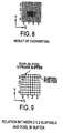
- point (1.6,1.3,Z) is shifted by (0.0,0.5), and, as shown in Figure 7(D), 1/4 of the color information that properly speaking is to be written in (the portion indicated by backslash-slanted dotted lines in Figure 7(D)) is written into the position of the pixel (1,1) that includes the subpixel that corresponds to the point (1.5,1.75,Zs) that is obtained by subpixel-precisioning this shifted point (1.6,1.8,Z) (indicated by the dark circle in Figure 7(D)). Specifically, in pixel (1,1), 1/4 of the color information that properly speaking is to be written in is added to the color information that has already been written in, and the value of the sum is written into pixel (1,1).
- the resolution can be increased essentially 4-fold, and as a result, antialiasing can be done.
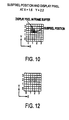
- the shift amount (dX,dY) for each of the four times that drawing is to be done is set to (0.0,0.0), (0.5,0.0), (0.5,0.5), (0.0,0.5) as described above, the position of the drawn point is sometimes shifted to the upper right of its proper position, so to prevent such a shift, the shift amounts (dX,dY) may be set to, for example, (-0.25,-0.25), (0.25,-0.25), (0.25,0.25), (-0.25,0.25) (so that the average value of shift amount dX or dY is 0 for each).
- point (1.6,2.2,Z) is to be drawn (for convenience, we omit the Z coordinate in the following)
- point (1.6,2.2) is subpixel-precisioned and is set to point (1.5,2.0) as indicated by the dark circle in Figure 10.
- the color information that properly speaking is to be written in is written into position (1,2) of the pixel that includes the subpixel that corresponds to point (1.5,2.0), as indicated by the slanting lines in Figure 10.
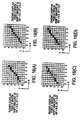
- Figs. 11(A)-11(D) show diagrams for explaining the overwriting of a point.
- GPU 115 sets each of the shift amounts (dX,dY) for the drawing position in the screen coordinate system when drawing is to be done the first through fourth times to, for example, (0.0,0.0), (0.5,0.0), (0.0,0.5), (0.5,0.5), respectively, which is in subpixel precision (here, 1/2 of a pixel). Then, in drawing the first time, point (1.6,2.2) is shifted by (0.0,0.0). Then this shifted point (1.6,2.2) is subpixel-precisioned and set to point (1.5,2.0), as indicated by the dark circle in Figure 11(A). Then color information that is 1/4 of the color information that properly speaking is to be written in is written to position (1,2) of the pixel that includes the subpixel that corresponds to point (1.5,2.0), as indicated by the vertical dotted lines in Figure 11(A).
- point (1.6,2.2) is shifted by (0.5,0.0). Then this shifted point (2.1,2.2) is subpixel-precisioned and set to point (2.0,2.0), as indicated by the dark circle in Figure 11(B). Then color information that is 1/4 of the color information that properly speaking is to be written in is written to position (2,2) of the pixel that includes the subpixel that corresponds to point (2.0,2.0), as indicated by the horizontal dotted lines in Figure 11(B).
- point (1.6,2.2) is shifted by (0.0,0.5). Then this shifted point (1.6,2.7) is subpixel-precisioned and set to point (1.5,2.5), as indicated by the dark circle in Figure 11(C). Then color information that is 1/4 of the color information that properly speaking is to be written in is written to position (1,2) of the pixel that includes the subpixel that corresponds to point (1.5,2.5), as indicated by the slash-slanted dotted lines in Figure 11(C).
- point (1.6,2.2) is shifted by (0.5,0.5). Then this shifted point (2.1,2.7) is subpixel-precisioned and set to point (2.0,2.5), as indicated by the dark circle in Figure 11(D). Then color information that is 1/4 of the color information that properly speaking is to be written in is written to position (2,2) of the pixel that includes the subpixel that corresponds to point (2.0,2.5), as indicated by the backslash-slanted dotted lines in Figure 11(D).
- subpixel precision is different in the case shown in Figures 7(A)-7(D) and the case in Figure 11(A)-11(D) (in Figures 7(A)-7(D) it is 1/16 the precision of a pixel, and in Figures 11(A)-11(D) it is 1/4 the precision of a pixel), but this too has no effect on the picture quality due to overwriting (if the overwriting is done four times, whether the subpixel precision is 1/4 or 1/16 has no effect on the improvement in the picture quality "due to overwriting," and if one considers overwriting, higher subpixel precision yields better picture quality).
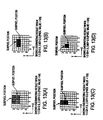
- Figures 13(A)-13(D) are diagrams for explaining the overwriting.
- the number of overwriting times is set to four times and the shift amounts when the four-time drawing is done are set to (0.0,0.0), (0.5,0.0), (0.0,0.5), (0.5,0.5), when the X or Y coordinate of point (X,Y) is, for example, greater than or equal to 1.5 and less than 2.0 or greater than or equal to 2.5 and less than 3.0, respectively, then the pixels represented by coordinates (1,2), (2,2), (1,3), (2,3) are drawn, respectively, when the drawing is done the first through fourth times, as shown in Figure 13(A).
- the pixel represented by coordinates (1,2) is drawn when the drawing is done the first through fourth times, as shown in Figure 13(D). And in this case, since color information that is 1/4 of the color information that properly speaking is to be written in is overwritten four times each to the pixel represented by coordinates (1,2), if now brightness is represented by 8 bits and the brightness of point (X,Y) is set to the maximum value of 255, then the brightness of the pixel represented by coordinates (1,2) becomes 255.
- the starting point or ending point of a line segment to be drawn is represented by (x1,y1,z1) or (x2,y2,z2), respectively. It is further stipulated that this starting point and ending point are points in the screen coordinate system after perspective transformation (perspective and projective transformation).
- GPU 115 sets each of the shift amounts (dX,dY) for the drawing position in the screen coordinate system when a line segment is drawn the first through fourth times to, for example, (0.0,0.0), (0.5,0.0), (0.5,0.5), (0.0,0.5), which is the precision of twice a subpixel (here, 1/2 of a pixel).
- CPU 115 draws the line segment by shifting the drawing position according to the shift amounts (dX,dY).
- GPU 115 shifts starting point (x1,y1,z1) and ending point (x2,y2,z2) each by (0.0,0.0) and determines the points interpolated with subpixel precision between the shifted starting point and ending point by DDA (Digital Differential Analysis) operation, which is discussed later, and the color information, etc. at these points.
- DDA Digital Differential Analysis
- the color information (as stated above, color information that is 1/4 the color information properly speaking) is written to the position of the pixels that include the subpixels that correspond to these points (X1s,Y1s,Z1s) through (Xns,Yns,Zns).
- pixels that include two or more subpixels corresponding to subpixel-precision points that constitute the line segment are to be drawn, and into the pixels that are to be drawn is written, as color information, for example (1/4 of) the average value of the color information of the subpixels included in the pixel.
- the drawing for the second through fourth times likewise is done in the same way as for the drawing for the first time, except that the shift amounts are set to (0.5,0.0), (0.5,0.5), (0.0,0.5), respectively.
- pixels that include one or more subpixels corresponding to subpixel-precision points that constitute the line segment are to be drawn, and into the pixels that are to be drawn is written, as color information, for example (1/4 of) the average value of the color information of the subpixels included in the pixel.
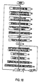
- step S1 main CPU 111 reads via main bus 101 for example the data for drawing the polygons that comprise one frame of a three-dimensional image and supplies it to GTE 117.
- GTE 117 With GTE 117, in step S2 geometry processing is done on each of the polygons in three-dimensional space based on the viewpoint, and the geometry-processed data is perspective-transformed.
- the viewpoint is given by, for example, the user's operation of the operation device 17 ( Figure 1).
- step S3 the polygon data is determined in main CPU 111 by performing brightness calculations and texture address calculations for the polygons in the screen coordinate system after they have been perspective-transformed, and they are supplied to GPU 115 via main bus 101.
- polygon data includes, for example, X, Y, Z, R, G, B, ⁇ , S, T, Q, F.
- the data X, Y, Z represent, respectively, the X, Y, Z coordinates of each of the three vertices of a triangular polygon
- R, G, B represent the red, green, and blue brightness value, respectively, of the three vertices.
- ⁇ represents a blend coefficient that represents the ratio of the blend if the RGB values of the pixel to be drawn and the RGB values of the already drawn pixel are to be ⁇ -blended.
- ⁇ is for example a real number greater than or equal to 0 and less than or equal to 1, and when the pixel values (RGB values) of the pixel to be drawn is denoted by F c and the pixel values of the already drawn pixel is denoted by B c , then the pixel value C c obtained as a result of ⁇ -blending them is given for example by the following equation.
- C c ⁇ F c +(1- ⁇ )B c
- S, T, Q represent the texture coordinates (homogeneous coordinates for texture) in each of the three vertices of a triangular polygon. That is, here a pattern (texture) is applied to the surface of an object by texture mapping, and S, T, Q are used in this texture mapping. The value obtained by multiplying S/Q, T/Q, respectively, by the texture size becomes the texture address.
- F is a fog value that represents the degree of fogginess when the pixel to be drawn is to be made foggy; for example, the higher this value is, the foggier it is displayed.
- step S4 the time for drawing one frame is estimated in main CPU 111. That is, main CPU 111 estimates from the number of polygons for which data was read in step S1, that is, from the number of polygons to be drawn in one frame, the drawing time needed for drawing the one frame, for example, one time. Then, in step S5, main CPU 111 determines the number of overwriting times N based on the drawing time estimated in step S4, and supplies it to GPU 115 via main bus 101.
- the number of overwriting times N is determined adaptively based on the drawing time for one frame, so that overwriting is done as many times as possible within a range that ensures that processing will not fail (here, a range at which the frame rate can be maintained).
- the overwriting number of times may be set to a fixed value that ensures that processing will not fail. And the effect that overwriting has on improving the picture quality is theoretically greatest if overwriting is done as many times as the number of subpixels that make up a pixel, with no additional effect obtained if the number of overwriting times is increased beyond this. Therefore in a case where the processing capacity of the equipment is sufficient and processing will not fail even if the overwriting number of times is set to greater than the number of subpixels that comprise a pixel, it is desirable that the number of overwriting times be set to the same as the number of subpixels that comprise a pixel, so as to avoid "wasteful" processing. For the same reason, even if the overwriting number of times is determined adaptively, it is desirable, when that number of times becomes greater than the number of subpixels that comprise a pixel, to limit it to the number of subpixels that comprise a pixel.
- step S6 in which main CPU 111 sets the shift amounts (dX,dY) used for each drawing time in the event that drawing is done as many times as the overwriting number of times N, and supplies them to GPU 115. It is desirable that the shift amounts be set to subpixel precision or better, and smaller than the precision of one pixel.
- step S7 a Z sort is performed to sort the polygons that comprise one frame into order by their depth direction.
- a Z sort is disclosed in, for example, unexamined patent application H7-114654 (1995).
- GPU 115 in step S8, clears frame buffer 141 to, for example, 0, then proceeds to step S9 and initializes the variable n, which counts the drawing number of times, to, for example, 1. Then, proceeding to step S10, GPU 115 corrects the shift amounts used for drawing each polygon the n-th time based on its movement.
- the polygon data includes, besides the data mentioned above, polygon motion vectors. Supposing now that the movement vector of a given polygon is (vx,vy) and that (dXn,dYn) is set as the shift amount used for drawing the polygon the n-th time, the shift amount (dXn,dYn) is corrected to, for example, (dXn+vx/N,dYn+vy/N). By drawing with the shift amounts corrected in this way, a motion blur effect can be obtained.
- step S11 In which GPU 115 shifts the coordinates of the vertices of each polygon by the corrected shift amount, then we proceed to step S12.
- step S12 Z buffer 142 is initialized in GPU 115 to, for example, + ⁇ (assuming here that the Z value grows larger the deeper into the screen a point is), then we proceed to step S13.
- step S13 the coordinates of the polygon vertices are subpixel-precisioned, and, by performing DDA arithmetic operation in subpixel precision, the RGB values, etc. of the subpixels that constitute the edges and interiors of the polygon are determined.
- DDA arithmetic operation means arithmetic operation that between two points determines, by linear interpolation, each value (RGB value, etc.) for the pixels that constitute the line segment that joins the two points. That is, for example when one of the two points is taken as the starting point and the other as the ending point and the starting point and ending point are assigned certain values, then the proportional change (ratio of change) in the values assigned to the starting point and ending point is determined by dividing the difference between the value assigned to the starting point and the value assigned to the ending point by the number of pixels that lie between the starting point and the ending point, and the value of each pixel that lies between the starting point and the ending point is determined by successively adding (integrating) this to the value assigned to the starting point as one proceeds from the starting point to the ending point.
- pixels p1, p2, p3 are given as the three vertices of a triangular polygon
- a DDA arithmetic operation is performed with subpixel precision with respect to subpixels p1 and p2, subpixels p2 and p3, and subpixels p1 and p3, thereby taking the X, Y coordinates as variables and determining the polygon data Z, R, G, B, ⁇ , S, T, Q for the subpixels along the three edges of the polygon as well as the polygon data Z, R, G, B, ⁇ , S, T, Q for the subpixels that lie in the interior of the polygon.
- step S14 overwriting processing is done whereby, in GPU 115, the RGB values of the pixels that constitute the polygon are written to frame buffer 141 using Z buffer 142.
- RGB values written to frame buffer 141 in step S14 are determined in GPU 115 in, for example, the following way.
- GPU 115 performs texture mapping based on the polygon data X, Y, Z, R, G, B, ⁇ , S, T, Q for the subpixels that constitute the polygon, which are the result of the DDA arithmetic operation. Specifically, CPU 115 computes texture address U(S/Q),V(T/Q) by, for example, dividing S, T each by Q, and by doing various filtering processing as necessary, it computes the texture color at the X, Y coordinates of each subpixel. That is, GPU 115 reads from texture memory 143 the texture data (Texture Color Data) corresponding to texture address U, V.
- texture data Textture Color Data
- GPU 115 performs various filtering processing on RGB values as this texture data and on RGB values as the results of DDA arithmetic operation; that is, for example, it mixes the two in a prescribed proportion, mixes a preset color in accordance with the fog value F, and calculates the final RGB values of each subpixel that constitutes the polygon.
- step S14 the RGB values determined as described above are written to frame buffer 141.
- the writing to frame buffer 141 is done in sequence, from nearest to the viewpoint to farthest, for the polygons that were Z-sorted in step S7 according to their depth direction. The reason for this is stated below.
- the RGB values of that subpixel are written into the address in frame buffer 141 that corresponds to the pixel that includes that subpixel, but if more than one of the subpixels that constitute a pixel are to be drawn, the RGB values of the multiple subpixels, for example their average value, are written to it.
- step S14 when the writing to frame buffer 141 of the RGB values for one frame is completed, control proceeds to step S15, where it is determined whether variable n is greater than the writing number of times N, and if it is decided that it is not greater, control proceeds to step S16, in which variable n is incremented by 1, then control returns to step S10. Then, in step S10, GPU 115 corrects the shift amounts used for drawing each polygon the n-th time based on its movement, and thereafter the processing of steps S10 through S16 is repeated until it is decided in step S15 that variable n is greater than overwriting number of times N. In this way, the overwriting is done.
- step S15 if in step S15 it is decided that variable n is greater than overwriting number of times N, that is, if overwriting has been done N times for the one frame, GPU 115 reads the RGB values for the one frame that are stored in frame buffer 141, outputs them to the display, and returns to step S1. Then, in step S1, main CPU 111 reads from main memory 112 via main bus 101 the data for drawing the polygons that constitute the three-dimensional image of the next frame, and thereafter the same processing is repeated, thereby displaying a moving image.
- the writing to frame buffer 141 is done as described above in sequence, from nearest to the viewpoint to farthest, for the polygons that were Z-sorted according to their depth direction; this is due to the fact that, as stated below, the writing of the RGB values to frame buffer 141 is done by overwriting, in which they are added to the RGB values previously written in frame buffer 141.
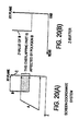
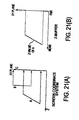
- Z buffer 142 is cleared in step S12 before the overwriting processing is done in step S14 as explained in the flowchart of Figure 18, after the entire frame C is written to frame buffer 141, Z buffer 142 is in a state in which a value corresponding to infinitely far (greatest depth) is written in as the Z value, as shown in Figure 19(B).
- the Z value recorded in Z buffer 142 represents infinite distance, so by drawing polygon B using Z buffer 142, that is, by adding the RGB values of polygon B to the RGB values already stored in frame buffer 141, the polygon B part of frame C already drawn in frame buffer 141 is overwritten, as shown in Figure 20(A). In this case, the Z value of polygon B is written into the part of Z buffer 142 that corresponds to polygon B.
- polygon A which lies nearer
- polygon B which lies farther away
- the Z value stored in Z buffer 142 represents infinite distance, so by drawing polygon A using Z buffer 142, that is, by adding the RGB values of polygon A to the RGB values already stored in frame buffer 141, the polygon A part of frame C already drawn in frame buffer 141 is overwritten. In this case, the Z value of polygon A is written to the part of Z buffer 142 that corresponds to polygon A.
- hidden-surface erasure in the case where overwriting is done can also be done by having a buffer (in the following referred to, for convenience, as the second frame buffer) of the same kind as frame buffer 141. That is, it suffices to draw to the second frame buffer using Z buffer 142 and overwrite the results of the second frame buffer in frame buffer 141. However, in this case, doing a Z sort is no longer necessary, but the second frame buffer must have the same capacity as frame buffer 141.
- the combination of Z sort and Z buffer 142 may also be used for generating natural images in cases where drawing is to be done with ⁇ blending, for example in cases where a semitransparent polygon is to be drawn or in cases where a shadow is to be drawn (for example, for semitransparent polygons using the combination of Z sort and Z buffer, a disclosure is made in, for example, patent application H8-158145 (1996), which was previously filed by the present applicant).
- the processing done using the combination of Z sort and Z buffer differs between cases in which hidden-line erasure is to be done when overwriting is done and cases in which semitransparent polygons are to be drawn, so switching between processing algorithms must be done in accordance with the particular case.
- step S14 we describe the details of the overwriting processing in step S14.
- Z(x,y) the pixel at the position x units from the left and y units from the bottom
- Z(x,y) the Z value of this pixel p(x,y)
- depth(x,y) the stored value corresponding to pixel p(x,y) that is stored in Z buffer 142.
- n(x,y) the stored value in the location of frame buffer 141 that corresponds to pixel p(x,y).
- step S21 a prescribed pixel p(x,y) among the pixels that constitute the frame to be drawn now is taken as the pixel of interest, and it is decided whether the Z value Z(x,y) of this pixel of interest p(x,y) is less than or equal to the value depth(x,y) stored in Z buffer 142.
- step S21 if it is decided that Z value Z(x,y) is not less than the stored value depth(x,y), that is, if there is a polygon that is nearer than the polygon that is composed including pixel of interest p(x,y) and it has not already been written to frame buffer 141, control returns to step S21, a pixel that has not yet been made a pixel of interest is newly made a pixel of interest, and thereafter the same processing is repeated.
- step S21 if it is decided that Z value Z(x,y) is less than or equal to stored valued depth(x,y), control proceeds to step S22, and brightness reduction processing is done. That is, if the RGB value of pixel of interest p(x,y) is denoted by M(x,y), RGB value M(x,y) is divided by overwriting number of times N, and the quotient (but here with the decimal part discarded) is determined as the RGB value m(x,y) to be overwritten.
- the RGB value m(x,y) to be overwritten can be set to the sum obtained by adding a prescribed correction value D to the value INT[M(x,y)/N].
- step S23 the stored value n(x,y) that corresponds to pixel of interest p(x,y) is read from frame buffer 141, control proceeds to step S24, and overwriting is done by adding it with the RGB value m(x,y) obtained after brightness reduction processing.
- the result of the addition is denoted by v(x,y).
- step S25 the result of the addition in step S24, that is, the overwriting result v(x,y), is overwritten into the location in frame buffer 141 where n(x,y) is stored (the location corresponding to pixel of interest p(x,y)). This v(x,y) is read as recorded value n(x,y) when pixel p(x,y) is next drawn.
- step S25 recorded value depth(x,y) in Z buffer 142 is rewritten to Z value Z(x,y), and control proceeds to step S26, in which it is decided whether all the pixels that comprise the frame to be drawn have been processed as pixels of interest.
- step S26 if it is decided that not all the pixels that comprise the frame to be drawn have been made a pixel of interest, control returns to step S21, a pixel that has not yet been made a pixel of interest is newly made a pixel of interest, and thereafter the same processing is repeated.
- step S26 If, on the other hand, it is decided in step S26 that all the pixels that comprise the frame to be drawn have been made a pixel of interest, a return is executed.
- N times INT[ ⁇ x M(x,y)] is less than the original RGB value M(x,y)
- A is corrected so that N times INT[ ⁇ x M(x,y)] is greater than or equal to the original RGB value M(x,y).
- it suffices to correct A to, for example, 33, which is 1 more than the 32 that corresponds to 1/4. If this is done, the brightness value for drawing one time becomes 65 ( INT[(255x33) ⁇ 7]), and if drawing at a brightness value of 65 is done four times, 260 results. And a value that exceeds 255, which is the maximum brightness value, is clipped to the maximum value 255.
- the image is overwritten by setting multiple shift amounts for shifting, with a precision finer than one pixel, the drawing position when the RGB value of each pixel is to be drawn to frame buffer 141 and by drawing the RGB values to the respective locations in frame buffer 141, and thus effective antialiasing can be done even without using a high-capacity, high-speed frame buffer or Z buffer.
- the antialiasing effect achieved by overwriting as described above extends not just to the edges of polygons but also to their interior and to the parts where three-dimensional shapes intersect each other, which not only reduces the jaggedness that occurs in straight lines but also improves the picture quality of the image as a whole.
- this invention was described for the case in which it is applied to a video game machine, but this invention may also be applied to effectors that give images special effects or to CAD and other devices that perform computer graphics processing.
- this invention may also be applied to, for example, recording and playback devices or transmission devices that encode natural images taken with, for example, a video camera and that record and play them back or transmit and receive them. That is, if in the future natural images taken with a video camera are encoded so as to be expressed by polygons, when they are played back, natural images of high picture quality can be played back by using the technique of this invention.
- drawing processing was done in frame units, but drawing processing may also be done in field units.
- This invention may also be applied to drawing either moving images or still images.
- the shift amount is not limited to subpixel precision but may be larger or smaller.
- the computer programs for performing the above-described drawing processing are provided recorded on CD-ROM 51.
- the computer programs may also be provided by, for example, Internet, satellite circuit, or other transmission medium.
- drawing processing need not be done by having a processor execute computer programs but may also be done on specialized hardware.
- three-dimensional images are displayed on a monitor display, but this invention may also be applied to other cases, such as, for example, printing three-dimensional images on a printer (a two-dimensional output device).
- drawing a one-frame image is done by shifting in both the X and Y directions, but it is also possible to do shifting in only one of these directions. That is, shifting amounts (dX,dY) may be set to, for example, (0.0,-0.2), (0.0,-0.1), (0.0,0.1), (0.0, 0.2).
- shift amount (dX,dY) may be predetermined, for example, for each overwriting number of times.
- the greater the number of overwrites the greater the improvement in the resolution, but as the number of overwrites is increased, the number of bits by which the RGB value drawn one time is reduced due to brightness reduction processing, and this worsens the gradation (grayscale) of the image. Therefore it is desirable that the number of overwrites be set not just from the standpoint of resolution, but in consideration of the gradation as well.
- multiple shift amounts are set for shifting, with precision finer than one pixel, the drawing position when pixel data is to be drawn to a pixel data memory means, and the image is overwritten by drawing pixel data to each location in the pixel data memory means that corresponds to the multiple shift amounts.
- computer programs are provided for overwriting images by setting multiple shift amounts for shifting, with precision finer than one pixel, and by drawing the pixel data to each memory location corresponding to the multiple shift amounts. Therefore it becomes possible to reduce the aliasing that occurs in the image.
- the drawing device, the drawing method, and a distribution medium of the present invention in, for example, three-dimensional graphic computers, which are image devices that employ a computer, or special effects devices (effectors), video game machines, or the like, the antialiasing effect extends not just to the edges of polygons but also to their interior and to the parts where three-dimensional shapes intersect each other, which not only reduces the jaggedness that occurs in straight lines but also improves the picture quality of the image as a whole. Therefore, the present invention is suitable for displaying images of high picture quality.
Landscapes
- Physics & Mathematics (AREA)
- Engineering & Computer Science (AREA)
- General Physics & Mathematics (AREA)
- Theoretical Computer Science (AREA)
- Computer Graphics (AREA)
- Geometry (AREA)
- Software Systems (AREA)
- Image Generation (AREA)
- Processing Or Creating Images (AREA)
- Controls And Circuits For Display Device (AREA)
- Image Processing (AREA)
Applications Claiming Priority (3)
| Application Number | Priority Date | Filing Date | Title |
|---|---|---|---|
| JP8537598 | 1998-03-31 | ||
| JP08537598A JP3639108B2 (ja) | 1998-03-31 | 1998-03-31 | 描画装置および描画方法、並びに提供媒体 |
| PCT/JP1999/001692 WO1999052077A1 (en) | 1998-03-31 | 1999-03-31 | Image drawing device, image drawing method, and providing medium |
Publications (3)
| Publication Number | Publication Date |
|---|---|
| EP1024458A1 true EP1024458A1 (de) | 2000-08-02 |
| EP1024458A4 EP1024458A4 (de) | 2004-05-06 |
| EP1024458B1 EP1024458B1 (de) | 2011-11-23 |
Family
ID=13856986
Family Applications (1)
| Application Number | Title | Priority Date | Filing Date |
|---|---|---|---|
| EP99912079A Expired - Lifetime EP1024458B1 (de) | 1998-03-31 | 1999-03-31 | Bild-zeichnungs-vorrichtung, bild-zeichnungs-verfahren, und ausstattungs-medium |
Country Status (15)
| Country | Link |
|---|---|
| US (1) | US6411290B1 (de) |
| EP (1) | EP1024458B1 (de) |
| JP (1) | JP3639108B2 (de) |
| KR (1) | KR100574786B1 (de) |
| CN (1) | CN1207690C (de) |
| AR (1) | AR017483A1 (de) |
| AU (1) | AU3054799A (de) |
| BR (1) | BR9904893A (de) |
| CA (1) | CA2292508A1 (de) |
| CO (1) | CO4840548A1 (de) |
| DZ (1) | DZ2749A1 (de) |
| RU (1) | RU2213373C2 (de) |
| TW (1) | TW430771B (de) |
| WO (1) | WO1999052077A1 (de) |
| ZA (1) | ZA992485B (de) |
Cited By (1)
| Publication number | Priority date | Publication date | Assignee | Title |
|---|---|---|---|---|
| JP2012208553A (ja) * | 2011-03-29 | 2012-10-25 | Sony Corp | 画像処理装置、および画像処理方法、並びにプログラム |
Families Citing this family (68)
| Publication number | Priority date | Publication date | Assignee | Title |
|---|---|---|---|---|
| US7212999B2 (en) | 1999-04-09 | 2007-05-01 | Trading Technologies International, Inc. | User interface for an electronic trading system |
| US6993504B1 (en) | 1999-04-09 | 2006-01-31 | Trading Technologies International, Inc. | User interface for semi-fungible trading |
| JP2001118049A (ja) * | 1999-10-14 | 2001-04-27 | Sega Corp | マトリクス演算器を有する画像処理装置 |
| US6772132B1 (en) | 2000-03-02 | 2004-08-03 | Trading Technologies International, Inc. | Click based trading with intuitive grid display of market depth |
| US6938011B1 (en) | 2000-03-02 | 2005-08-30 | Trading Technologies International, Inc. | Click based trading with market depth display |
| US7127424B2 (en) | 2000-03-02 | 2006-10-24 | Trading Technologies International, Inc. | Click based trading with intuitive grid display of market depth and price consolidation |
| US7389268B1 (en) | 2000-03-02 | 2008-06-17 | Trading Technologies International, Inc. | Trading tools for electronic trading |
| CN1204752C (zh) | 2000-04-14 | 2005-06-01 | 西门子公司 | 存储和处理时间上顺序排列图象的图象信息的方法和装置 |
| JP2002140722A (ja) * | 2000-08-23 | 2002-05-17 | Sony Computer Entertainment Inc | エイリアシングを除去した画像を描画する装置及び方法 |
| JP4632531B2 (ja) * | 2000-12-18 | 2011-02-16 | 株式会社バンダイナムコゲームス | ゲームシステム、情報記憶媒体及びゲームシステムの制御方法 |
| US6996537B2 (en) | 2001-08-13 | 2006-02-07 | Qualcomm Incorporated | System and method for providing subscribed applications on wireless devices over a wireless network |
| US9203923B2 (en) | 2001-08-15 | 2015-12-01 | Qualcomm Incorporated | Data synchronization interface |
| US7738533B2 (en) | 2002-01-07 | 2010-06-15 | Qualcomm Incorporated | Multiplexed CDMA and GPS searching |
| US6897879B2 (en) * | 2002-03-14 | 2005-05-24 | Microsoft Corporation | Hardware-enhanced graphics acceleration of pixel sub-component-oriented images |
| CN100356407C (zh) * | 2003-03-28 | 2007-12-19 | 奥林巴斯株式会社 | 数据创建设备 |
| US7646817B2 (en) * | 2003-03-28 | 2010-01-12 | Microsoft Corporation | Accelerating video decoding using a graphics processing unit |
| US9629030B2 (en) | 2003-10-14 | 2017-04-18 | Qualcomm Incorporated | Data rate control in soft handoff and during cell-switching |
| US8037515B2 (en) | 2003-10-29 | 2011-10-11 | Qualcomm Incorporated | Methods and apparatus for providing application credentials |
| NZ548673A (en) | 2004-01-21 | 2008-11-28 | Qualcomm Inc | Application-based value billing in a wireless subscriber network |
| US20070060358A1 (en) | 2005-08-10 | 2007-03-15 | Amaitis Lee M | System and method for wireless gaming with location determination |
| US8092303B2 (en) | 2004-02-25 | 2012-01-10 | Cfph, Llc | System and method for convenience gaming |
| US7534169B2 (en) | 2005-07-08 | 2009-05-19 | Cfph, Llc | System and method for wireless gaming system with user profiles |
| US8616967B2 (en) | 2004-02-25 | 2013-12-31 | Cfph, Llc | System and method for convenience gaming |
| KR101254209B1 (ko) | 2004-03-22 | 2013-04-23 | 삼성전자주식회사 | 디바이스와 휴대용 저장장치간에 권리 객체를 이동,복사하는 방법 및 장치 |
| US7999806B2 (en) * | 2004-07-23 | 2011-08-16 | Panasonic Corporation | Three-dimensional shape drawing device and three-dimensional shape drawing method |
| US7178111B2 (en) * | 2004-08-03 | 2007-02-13 | Microsoft Corporation | Multi-planar three-dimensional user interface |
| USD523022S1 (en) * | 2004-12-28 | 2006-06-13 | Action Electronics Co., Ltd. | Carriageable multimedia receiver |
| USD521525S1 (en) * | 2004-12-28 | 2006-05-23 | Action Electronics Co., Ltd. | Carriageable multimedia receiver |
| US9350875B2 (en) | 2005-05-31 | 2016-05-24 | Qualcomm Incorporated | Wireless subscriber billing and distribution |
| US9185538B2 (en) | 2005-05-31 | 2015-11-10 | Qualcomm Incorporated | Wireless subscriber application and content distribution and differentiated pricing |
| JP4727304B2 (ja) * | 2005-06-06 | 2011-07-20 | パナソニック株式会社 | 曲線描画装置、曲線描画方法、駐車支援装置及び車両 |
| US10510214B2 (en) | 2005-07-08 | 2019-12-17 | Cfph, Llc | System and method for peer-to-peer wireless gaming |
| US8070604B2 (en) | 2005-08-09 | 2011-12-06 | Cfph, Llc | System and method for providing wireless gaming as a service application |
| US8269788B2 (en) * | 2005-11-15 | 2012-09-18 | Advanced Micro Devices Inc. | Vector graphics anti-aliasing |
| KR101370356B1 (ko) * | 2005-12-02 | 2014-03-05 | 코닌클리케 필립스 엔.브이. | 스테레오스코픽 화상 디스플레이 방법 및 장치, 2d 화상데이터 입력으로부터 3d 화상 데이터를 생성하는 방법,그리고 2d 화상 데이터 입력으로부터 3d 화상 데이터를생성하는 장치 |
| WO2007099494A1 (en) * | 2006-03-01 | 2007-09-07 | Koninklijke Philips Electronics, N.V. | Motion adaptive ambient lighting |
| US9143622B2 (en) | 2006-02-17 | 2015-09-22 | Qualcomm Incorporated | Prepay accounts for applications, services and content for communication devices |
| US9185234B2 (en) | 2006-02-22 | 2015-11-10 | Qualcomm Incorporated | Automated account mapping in a wireless subscriber billing system |
| US7644861B2 (en) | 2006-04-18 | 2010-01-12 | Bgc Partners, Inc. | Systems and methods for providing access to wireless gaming devices |
| US7549576B2 (en) | 2006-05-05 | 2009-06-23 | Cfph, L.L.C. | Systems and methods for providing access to wireless gaming devices |
| US12136314B2 (en) | 2006-05-05 | 2024-11-05 | Cfph, Llc | Game access device with time varying signal |
| US8939359B2 (en) | 2006-05-05 | 2015-01-27 | Cfph, Llc | Game access device with time varying signal |
| EP1889732A1 (de) * | 2006-08-18 | 2008-02-20 | Setec Oy | Methode zum Übereinanderlegen von Abbildungen und Methode zur Personalisierung von Dokumenten mit der Methode |
| US9306952B2 (en) | 2006-10-26 | 2016-04-05 | Cfph, Llc | System and method for wireless gaming with location determination |
| US9411944B2 (en) | 2006-11-15 | 2016-08-09 | Cfph, Llc | Biometric access sensitivity |
| US8645709B2 (en) | 2006-11-14 | 2014-02-04 | Cfph, Llc | Biometric access data encryption |
| US8581721B2 (en) | 2007-03-08 | 2013-11-12 | Cfph, Llc | Game access device with privileges |
| US8319601B2 (en) | 2007-03-14 | 2012-11-27 | Cfph, Llc | Game account access device |
| US9183693B2 (en) | 2007-03-08 | 2015-11-10 | Cfph, Llc | Game access device |
| JP5298507B2 (ja) * | 2007-11-12 | 2013-09-25 | セイコーエプソン株式会社 | 画像表示装置及び画像表示方法 |
| JP5006272B2 (ja) * | 2008-06-13 | 2012-08-22 | 株式会社東芝 | 電線格納部品の図面作成装置とその方法、およびプログラム |
| US8737281B2 (en) * | 2008-06-18 | 2014-05-27 | Thomson Licensing | Apparatus for multicast transmissions in wireless local area networks |
| WO2009154593A1 (en) * | 2008-06-18 | 2009-12-23 | Thomson Licensing | Contention-based medium reservation method and apparatus for multicast transmissions in wireless local area networks |
| JP5415533B2 (ja) * | 2008-06-23 | 2014-02-12 | トムソン ライセンシング | 通信方法及び通信局 |
| US8462686B2 (en) * | 2008-06-23 | 2013-06-11 | Thomson Licensing | Apparatus for collision mitigation of multicast transmissions in wireless networks |
| JP5637988B2 (ja) * | 2008-06-26 | 2014-12-10 | トムソン ライセンシングThomson Licensing | 無線ローカル・エリア・ネットワークにおいてマルチキャスト・データの確認応答の要求および伝送を行う装置 |
| JP5317235B2 (ja) * | 2008-06-26 | 2013-10-16 | トムソン ライセンシング | 無線ローカル・エリア・ネットワークにおいてマルチキャスト・データの確認応答および再伝送を行う方法および装置 |
| JP5200743B2 (ja) | 2008-08-01 | 2013-06-05 | セイコーエプソン株式会社 | 画像処理装置、画像表示装置、画像処理方法、画像表示方法及びプログラム |
| WO2010058546A1 (ja) * | 2008-11-18 | 2010-05-27 | パナソニック株式会社 | 立体視再生を行う再生装置、再生方法、プログラム |
| CN102301397A (zh) * | 2008-12-01 | 2011-12-28 | 北方电讯网络有限公司 | 用于提供计算机生成的三维虚拟环境的视频表示的方法和设备 |
| US8956231B2 (en) | 2010-08-13 | 2015-02-17 | Cfph, Llc | Multi-process communication regarding gaming information |
| US8974302B2 (en) | 2010-08-13 | 2015-03-10 | Cfph, Llc | Multi-process communication regarding gaming information |
| US20220296999A1 (en) | 2010-08-13 | 2022-09-22 | Cfph, Llc | Multi-process communication regarding gaming information |
| JP5817093B2 (ja) * | 2010-08-20 | 2015-11-18 | セイコーエプソン株式会社 | 映像処理装置、及び映像表示装置 |
| CN103164839B (zh) * | 2013-03-07 | 2019-06-21 | 华为技术有限公司 | 一种绘图方法、装置及终端 |
| KR102335113B1 (ko) | 2014-12-22 | 2021-12-03 | 삼성디스플레이 주식회사 | 표시 장치 및 그 구동 방법 |
| CN110335190A (zh) * | 2019-06-20 | 2019-10-15 | 合肥芯碁微电子装备有限公司 | 基于cuda的直写式光刻机数据拓展方法 |
| JP7433703B2 (ja) * | 2020-01-16 | 2024-02-20 | アルパイン株式会社 | 表示制御装置および表示制御方法 |
Family Cites Families (15)
| Publication number | Priority date | Publication date | Assignee | Title |
|---|---|---|---|---|
| JPS63113785A (ja) | 1986-10-31 | 1988-05-18 | Hitachi Ltd | 図形表示方法 |
| CA2030022A1 (en) * | 1989-11-17 | 1991-05-18 | Brian M. Kelleher | System and method for drawing antialiased polygons |
| EP0466936B1 (de) * | 1990-02-05 | 1997-04-16 | Ricoh Company, Ltd | Animationsanzeigeeinheit und dafür verwendeter externer speicher |
| DE69127516T2 (de) * | 1990-06-29 | 1998-02-26 | Philips Electronics Nv | Verfahren und Gerät zur Bilderzeugung |
| JP2569952B2 (ja) | 1990-11-30 | 1997-01-08 | ダイキン工業株式会社 | Aーバッファ法における隠面処理方法およびその装置 |
| GB2255466B (en) * | 1991-04-30 | 1995-01-25 | Sony Broadcast & Communication | Digital video effects system for producing moving effects |
| JP3151079B2 (ja) * | 1993-04-05 | 2001-04-03 | 日本電信電話株式会社 | アニメーションのエイリアシング除去方法 |
| JPH07282274A (ja) * | 1994-04-04 | 1995-10-27 | Mitsubishi Electric Corp | グラフィック表示装置 |
| JPH07282271A (ja) * | 1994-04-08 | 1995-10-27 | Hitachi Ltd | 画像処理方式 |
| US5748786A (en) * | 1994-09-21 | 1998-05-05 | Ricoh Company, Ltd. | Apparatus for compression using reversible embedded wavelets |
| RU2093968C1 (ru) * | 1995-08-02 | 1997-10-20 | Закрытое акционерное общество "Техно-ТМ" | Способ кодирования-декодирования изображений и устройство для его осуществления |
| US5949924A (en) * | 1995-10-06 | 1999-09-07 | Ricoh Company, Ltd. | Image processing apparatus, method and computer program product |
| JP3712015B2 (ja) * | 1995-10-19 | 2005-11-02 | ソニー株式会社 | 画像作成装置および方法 |
| US6163337A (en) * | 1996-04-05 | 2000-12-19 | Matsushita Electric Industrial Co., Ltd. | Multi-view point image transmission method and multi-view point image display method |
| JP2858556B2 (ja) * | 1996-04-17 | 1999-02-17 | 日本電気株式会社 | 3次元形状通信システム |
-
1998
- 1998-03-31 JP JP08537598A patent/JP3639108B2/ja not_active Expired - Lifetime
-
1999
- 1999-03-29 US US09/281,134 patent/US6411290B1/en not_active Expired - Lifetime
- 1999-03-31 BR BR9904893-0A patent/BR9904893A/pt not_active IP Right Cessation
- 1999-03-31 AR ARP990101494A patent/AR017483A1/es unknown
- 1999-03-31 EP EP99912079A patent/EP1024458B1/de not_active Expired - Lifetime
- 1999-03-31 CO CO99019439A patent/CO4840548A1/es unknown
- 1999-03-31 ZA ZA9902485A patent/ZA992485B/xx unknown
- 1999-03-31 RU RU99128068/09A patent/RU2213373C2/ru not_active IP Right Cessation
- 1999-03-31 CN CNB998008680A patent/CN1207690C/zh not_active Expired - Fee Related
- 1999-03-31 KR KR1019997011012A patent/KR100574786B1/ko not_active Expired - Fee Related
- 1999-03-31 WO PCT/JP1999/001692 patent/WO1999052077A1/ja not_active Ceased
- 1999-03-31 CA CA002292508A patent/CA2292508A1/en not_active Abandoned
- 1999-03-31 TW TW088105143A patent/TW430771B/zh not_active IP Right Cessation
- 1999-03-31 AU AU30547/99A patent/AU3054799A/en not_active Abandoned
- 1999-03-31 DZ DZ990050A patent/DZ2749A1/xx active
Cited By (1)
| Publication number | Priority date | Publication date | Assignee | Title |
|---|---|---|---|---|
| JP2012208553A (ja) * | 2011-03-29 | 2012-10-25 | Sony Corp | 画像処理装置、および画像処理方法、並びにプログラム |
Also Published As
| Publication number | Publication date |
|---|---|
| EP1024458B1 (de) | 2011-11-23 |
| CA2292508A1 (en) | 1999-10-14 |
| AU3054799A (en) | 1999-10-25 |
| JP3639108B2 (ja) | 2005-04-20 |
| RU2213373C2 (ru) | 2003-09-27 |
| EP1024458A4 (de) | 2004-05-06 |
| CN1272194A (zh) | 2000-11-01 |
| JPH11283041A (ja) | 1999-10-15 |
| US6411290B1 (en) | 2002-06-25 |
| KR20010013036A (ko) | 2001-02-26 |
| KR100574786B1 (ko) | 2006-04-28 |
| BR9904893A (pt) | 2000-10-17 |
| WO1999052077A1 (en) | 1999-10-14 |
| AR017483A1 (es) | 2001-09-05 |
| ZA992485B (en) | 1999-10-07 |
| TW430771B (en) | 2001-04-21 |
| DZ2749A1 (fr) | 2003-09-15 |
| CN1207690C (zh) | 2005-06-22 |
| CO4840548A1 (es) | 1999-09-27 |
Similar Documents
| Publication | Publication Date | Title |
|---|---|---|
| EP1024458B1 (de) | Bild-zeichnungs-vorrichtung, bild-zeichnungs-verfahren, und ausstattungs-medium | |
| US6480192B1 (en) | Recording medium, apparatus and method for processing images | |
| EP0806743B1 (de) | Datenverarbeitungsverfahren und -gerät | |
| US8013865B2 (en) | Program, information storage medium, image generation system, and image generation method for generating an image for overdriving the display device | |
| US20060046844A1 (en) | Video game device and image processing program | |
| US20030011610A1 (en) | Game system and image creating method | |
| EP1312047B1 (de) | Verfahren und gerät zur unverfälschten bildwiedergabe | |
| EP1174829B1 (de) | Dreidimensionale Bildverarbeitungseinheit | |
| GB2363956A (en) | Game system and image creating method | |
| JP4917346B2 (ja) | ゲーム画像処理プログラムおよびゲーム画像処理装置 | |
| US20010041619A1 (en) | Game apparatus, storage medium and computer program | |
| CA2316611A1 (en) | Method and apparatus for providing depth blur effects within a 3d videographics system | |
| JP4074531B2 (ja) | 描画装置および描画方法、並びに提供媒体 | |
| US6856321B2 (en) | Texture rendering method, entertainment apparatus and storage medium | |
| HK1030078A (en) | Image drawing device, image drawing method, and providing medium | |
| EP1394748A1 (de) | Bildverarbeitungsverfahren | |
| NZ500121A (en) | Reduction of aliasing in 3D images by multiple small shifts of pixel values. | |
| JP4447000B2 (ja) | 画像生成システム、プログラム及び情報記憶媒体 | |
| MXPA99011024A (en) | Image drawing device, image drawing method, and providing medium | |
| JP2002083315A (ja) | 画像描画システム | |
| HK1033021A (en) | Recording medium, image processing device, and image processing method | |
| JP2004030283A (ja) | 画像生成システム、プログラム及び情報記憶媒体 |
Legal Events
| Date | Code | Title | Description |
|---|---|---|---|
| PUAI | Public reference made under article 153(3) epc to a published international application that has entered the european phase |
Free format text: ORIGINAL CODE: 0009012 |
|
| 17P | Request for examination filed |
Effective date: 20000414 |
|
| AK | Designated contracting states |
Kind code of ref document: A1 Designated state(s): BE CH DE DK ES FI FR GB IT LI NL SE |
|
| A4 | Supplementary search report drawn up and despatched |
Effective date: 20040318 |
|
| RIC1 | Information provided on ipc code assigned before grant |
Ipc: 7G 06T 15/50 B Ipc: 7G 06T 11/20 B Ipc: 7G 06T 15/00 A |
|
| 17Q | First examination report despatched |
Effective date: 20040712 |
|
| REG | Reference to a national code |
Ref country code: HK Ref legal event code: WD Ref document number: 1030078 Country of ref document: HK |
|
| GRAP | Despatch of communication of intention to grant a patent |
Free format text: ORIGINAL CODE: EPIDOSNIGR1 |
|
| GRAS | Grant fee paid |
Free format text: ORIGINAL CODE: EPIDOSNIGR3 |
|
| GRAA | (expected) grant |
Free format text: ORIGINAL CODE: 0009210 |
|
| AK | Designated contracting states |
Kind code of ref document: B1 Designated state(s): BE CH DE DK ES FI FR GB IT LI NL SE |
|
| REG | Reference to a national code |
Ref country code: GB Ref legal event code: FG4D |
|
| REG | Reference to a national code |
Ref country code: CH Ref legal event code: EP |
|
| REG | Reference to a national code |
Ref country code: DE Ref legal event code: R096 Ref document number: 69943872 Country of ref document: DE Effective date: 20120202 |
|
| REG | Reference to a national code |
Ref country code: NL Ref legal event code: VDEP Effective date: 20111123 |
|
| PG25 | Lapsed in a contracting state [announced via postgrant information from national office to epo] |
Ref country code: SE Free format text: LAPSE BECAUSE OF FAILURE TO SUBMIT A TRANSLATION OF THE DESCRIPTION OR TO PAY THE FEE WITHIN THE PRESCRIBED TIME-LIMIT Effective date: 20111123 Ref country code: NL Free format text: LAPSE BECAUSE OF FAILURE TO SUBMIT A TRANSLATION OF THE DESCRIPTION OR TO PAY THE FEE WITHIN THE PRESCRIBED TIME-LIMIT Effective date: 20111123 Ref country code: BE Free format text: LAPSE BECAUSE OF FAILURE TO SUBMIT A TRANSLATION OF THE DESCRIPTION OR TO PAY THE FEE WITHIN THE PRESCRIBED TIME-LIMIT Effective date: 20111123 |
|
| PGFP | Annual fee paid to national office [announced via postgrant information from national office to epo] |
Ref country code: GB Payment date: 20120328 Year of fee payment: 14 |
|
| PG25 | Lapsed in a contracting state [announced via postgrant information from national office to epo] |
Ref country code: DK Free format text: LAPSE BECAUSE OF FAILURE TO SUBMIT A TRANSLATION OF THE DESCRIPTION OR TO PAY THE FEE WITHIN THE PRESCRIBED TIME-LIMIT Effective date: 20111123 |
|
| PG25 | Lapsed in a contracting state [announced via postgrant information from national office to epo] |
Ref country code: IT Free format text: LAPSE BECAUSE OF FAILURE TO SUBMIT A TRANSLATION OF THE DESCRIPTION OR TO PAY THE FEE WITHIN THE PRESCRIBED TIME-LIMIT Effective date: 20111123 |
|
| PLBE | No opposition filed within time limit |
Free format text: ORIGINAL CODE: 0009261 |
|
| STAA | Information on the status of an ep patent application or granted ep patent |
Free format text: STATUS: NO OPPOSITION FILED WITHIN TIME LIMIT |
|
| REG | Reference to a national code |
Ref country code: DE Ref legal event code: R119 Ref document number: 69943872 Country of ref document: DE |
|
| 26N | No opposition filed |
Effective date: 20120824 |
|
| REG | Reference to a national code |
Ref country code: CH Ref legal event code: PL |
|
| REG | Reference to a national code |
Ref country code: FR Ref legal event code: ST Effective date: 20121130 |
|
| REG | Reference to a national code |
Ref country code: DE Ref legal event code: R097 Ref document number: 69943872 Country of ref document: DE Effective date: 20120824 |
|
| PG25 | Lapsed in a contracting state [announced via postgrant information from national office to epo] |
Ref country code: LI Free format text: LAPSE BECAUSE OF NON-PAYMENT OF DUE FEES Effective date: 20120331 Ref country code: FR Free format text: LAPSE BECAUSE OF NON-PAYMENT OF DUE FEES Effective date: 20120402 Ref country code: CH Free format text: LAPSE BECAUSE OF NON-PAYMENT OF DUE FEES Effective date: 20120331 |
|
| REG | Reference to a national code |
Ref country code: DE Ref legal event code: R119 Ref document number: 69943872 Country of ref document: DE Effective date: 20121002 |
|
| PG25 | Lapsed in a contracting state [announced via postgrant information from national office to epo] |
Ref country code: ES Free format text: LAPSE BECAUSE OF FAILURE TO SUBMIT A TRANSLATION OF THE DESCRIPTION OR TO PAY THE FEE WITHIN THE PRESCRIBED TIME-LIMIT Effective date: 20120305 |
|
| PG25 | Lapsed in a contracting state [announced via postgrant information from national office to epo] |
Ref country code: FI Free format text: LAPSE BECAUSE OF FAILURE TO SUBMIT A TRANSLATION OF THE DESCRIPTION OR TO PAY THE FEE WITHIN THE PRESCRIBED TIME-LIMIT Effective date: 20111123 |
|
| GBPC | Gb: european patent ceased through non-payment of renewal fee |
Effective date: 20130331 |
|
| PG25 | Lapsed in a contracting state [announced via postgrant information from national office to epo] |
Ref country code: GB Free format text: LAPSE BECAUSE OF NON-PAYMENT OF DUE FEES Effective date: 20130331 |
|
| PG25 | Lapsed in a contracting state [announced via postgrant information from national office to epo] |
Ref country code: DE Free format text: LAPSE BECAUSE OF FAILURE TO SUBMIT A TRANSLATION OF THE DESCRIPTION OR TO PAY THE FEE WITHIN THE PRESCRIBED TIME-LIMIT Effective date: 20121002 |