EP1024284A2 - Système de commande pour pompe hydraulique - Google Patents
Système de commande pour pompe hydraulique Download PDFInfo
- Publication number
- EP1024284A2 EP1024284A2 EP00101184A EP00101184A EP1024284A2 EP 1024284 A2 EP1024284 A2 EP 1024284A2 EP 00101184 A EP00101184 A EP 00101184A EP 00101184 A EP00101184 A EP 00101184A EP 1024284 A2 EP1024284 A2 EP 1024284A2
- Authority
- EP
- European Patent Office
- Prior art keywords
- pressure
- fluid
- shuttle
- fluid path
- defining
- Prior art date
- Legal status (The legal status is an assumption and is not a legal conclusion. Google has not performed a legal analysis and makes no representation as to the accuracy of the status listed.)
- Withdrawn
Links
- 239000012530 fluid Substances 0.000 claims abstract description 109
- 230000007935 neutral effect Effects 0.000 claims abstract description 58
- 238000006073 displacement reaction Methods 0.000 claims abstract description 24
- 230000002706 hydrostatic effect Effects 0.000 claims description 12
- 230000004044 response Effects 0.000 claims description 6
- 210000003734 kidney Anatomy 0.000 description 12
- 230000007246 mechanism Effects 0.000 description 7
- 238000005086 pumping Methods 0.000 description 5
- 230000006835 compression Effects 0.000 description 4
- 238000007906 compression Methods 0.000 description 4
- 230000004075 alteration Effects 0.000 description 2
- 238000012986 modification Methods 0.000 description 2
- 230000004048 modification Effects 0.000 description 2
- 230000001419 dependent effect Effects 0.000 description 1
- 230000001050 lubricating effect Effects 0.000 description 1
- 238000005461 lubrication Methods 0.000 description 1
- 230000013011 mating Effects 0.000 description 1
- 238000004806 packaging method and process Methods 0.000 description 1
- 230000000717 retained effect Effects 0.000 description 1
- 125000006850 spacer group Chemical group 0.000 description 1
- 230000007704 transition Effects 0.000 description 1
Images


Classifications
-
- F—MECHANICAL ENGINEERING; LIGHTING; HEATING; WEAPONS; BLASTING
- F04—POSITIVE - DISPLACEMENT MACHINES FOR LIQUIDS; PUMPS FOR LIQUIDS OR ELASTIC FLUIDS
- F04B—POSITIVE-DISPLACEMENT MACHINES FOR LIQUIDS; PUMPS
- F04B1/00—Multi-cylinder machines or pumps characterised by number or arrangement of cylinders
- F04B1/12—Multi-cylinder machines or pumps characterised by number or arrangement of cylinders having cylinder axes coaxial with, or parallel or inclined to, main shaft axis
- F04B1/26—Control
- F04B1/30—Control of machines or pumps with rotary cylinder blocks
- F04B1/32—Control of machines or pumps with rotary cylinder blocks by varying the relative positions of a swash plate and a cylinder block
- F04B1/324—Control of machines or pumps with rotary cylinder blocks by varying the relative positions of a swash plate and a cylinder block by changing the inclination of the swash plate
Definitions
- the present invention relates to variable displacement hydraulic pumps having a rotating group and a tiltable swashplate for varying the displacement of the rotating group, and more particularly, to a "wide band neutral" arrangement for such pumps, i.e., a device which substantially eliminates flow from the pump, when the swashplate is close to neutral, even if the pump is not at absolute zero displacement.
- the hydraulic pump for use with the present invention may include various types of rotating groups, it is especially advantageous when used with a rotating group of the "axial piston" type, i.e ., one which includes a rotating cylinder barrel defining a plurality of cylinders, and a piston reciprocable within each cylinder. Therefore, the present invention will be described in connection with such an axial piston pump.
- a rotating group of the "axial piston” type i.e ., one which includes a rotating cylinder barrel defining a plurality of cylinders, and a piston reciprocable within each cylinder. Therefore, the present invention will be described in connection with such an axial piston pump.
- tiltable swashplate includes a pair of transversely opposed trunnions which are rotatably supported, relative to the pump housing, by suitable bearing means.
- a pump of the type described is sometimes referred to as a "trunnion pump”.
- Changes in displacement of an axial piston pump may be accomplished either by an appropriate servo mechanism or by a manual input. In either case, it is important for the pump to be able to achieve true neutral, such that there is no substantial flow of pressurized fluid out of the pump when the vehicle operator selects neutral operation of the pump. As is well known to those skilled in the art, the inability of a variable displacement axial piston pump to achieve neutral is extremely undesirable, especially in a vehicle propel system, because even a small flow of pressurized fluid may result in vehicle "creep", i.e., unintended movement of the vehicle, which at the very least, can be annoying to the operator, and may in some situations also be potentially dangerous.
- the servo mechanism itself may include an appropriate centering device, i.e. , a device which biases the pump displacement toward zero, in the absence of some sort of input displacement command.
- the wide band neutral arrangement of the present invention may be used advantageously with a servo controlled pump because, typically, there are limitations in accuracy of the return-to-neutral mechanism within the servo mechanism.
- a variable displacement hydrostatic pump of the type comprising housing means defining a source of case pressure.
- a cylinder barrel is rotatably mounted within the housing means and defines a plurality of cylinders, and a piston is disposed within each cylinder.
- a cam means is disposed within the housing means and is pivotable relative thereto, and includes a swashplate operably associated with each of the pistons to cause reciprocal movement thereof in response to rotation of the cylinder barrel when the cam means is displaced from a neutral position.
- the housing means and the pistons cooperate to define a first pressure fluid path, and a second pressure fluid path when the cam means is displaced from the neutral position.
- the improved pump is characterized by one of the housing means and the swashplate defining a shuttle bore interconnecting the first pressure fluid path and the second pressure fluid path.
- An open-center shuttle assembly is operably disposed in the shuttle bore to define a first pressure chamber in fluid communication with the first pressure fluid path, and a second pressure chamber in fluid communication with the second pressure fluid path.
- the shuttle bore defines first and second shuttle seats, and the shuttle bore, intermediate the shuttle seats, is in fluid communication with the source of case pressure.
- a means biases the open-center shuttle assembly toward a centered position, in the absence of fluid pressure, in excess of a predetermined fluid pressure, in one of the first and second pressure chambers.
- both of the first and second pressure fluid paths are in relatively unrestricted fluid communication with the source of case pressure.
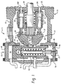
- FIG. 1 illustrates a variable displacement axial piston pump, generally designated 11, of a type with which the present invention may be utilized.
- the pump 11 comprises two main portions: a pumping element 13 and a fluid pressure actuated servo-assembly 15.
- the pumping element 13 includes a pump housing 19 which defines an internal cavity 21.
- An input shaft 23 extends into the internal cavity 21, and then extends to the right through an opening in a port housing 25 to drive a charge pump (not shown herein).
- the port housing 25 is also sometimes referred to as a back plate or as an end cap.
- the term "housing means" may mean and include both the pump housing 19 and the back plate 25, in view of the fact that the housing 19 and back plate 25 cooperate to define the internal cavity 21.
- a cylinder barrel 29 Disposed about the input shaft 23, within the internal cavity 21, is a cylinder barrel 29 which is splined to the input shaft 23 to rotate therewith.
- the rotatable barrel 29 defines a plurality of cylinder bores 31, and disposed for reciprocating movement within each bore 31 is a piston 33.
- Each piston 33 includes a generally spherical head which is received within a piston shoe 35 (also sometimes referred to as a "slipper").
- the piston shoes 35 are retained in contact with a swashplate 37 in a manner generally well known to those skilled in the art.
- the swashplate 37 is carried by a cam member 39, which is typically mounted in a cam support 41.
- the swashplate 37 may merely comprise the surface of the cam member 39, as in the subject embodiment, or comprise a separate member. Therefore, "37" will be used hereinafter to refer either to the swashplate surface or to the cam surface.
- the cam member 39 is shown in its neutral position, and movement of the cam member from the neutral position in either direction will result in the stroke of the pistons 33 being changed in such a way that rotation of the barrel 29 will result in an output flow of pressurized fluid from the pumping element 13.
- the housing 19, the cylinders 31 and the pistons 33 cooperate to define a pair of "pressure fluid paths", one on the suction (inlet) side of the pump, and the other on the discharge (outlet) side of the pump.
- the fluid pressure actuated servo-assembly 15 comprises, in the subject embodiment, a separate servo-housing 43 suitably attached to the pump housing 19.
- the servo-housing 43 defines a servo-cylinder 45, and axially displaceable therein is a servo-piston 47, which is shown in its neutral position in FIG. 1, corresponding to the neutral position of the cam member 39.
- Bolted to the servo-housing 43 is an upper end cap 49, and a lower end cap 51, the end caps 49 and 51 cooperating with the housing 43 and the piston 47 to define upper and lower servo-chambers 53 and 55, respectively.
- the servo-piston 47 is provided with a neutral centering spring assembly 57, the function of which is to return the servo-piston 47 to its neutral position shown in FIG. 1, in the absence of control fluid pressure in either of the chambers 53 or 55.
- the neutral centering spring assembly 57 primarily comprises a spring support member 59, and a coil compression spring 61.
- the servo-piston 47 defines an annular groove 63 which receives the forward end of a servo piston follower 65.
- the follower 65 is attached to the cam member 39 by means of a follower pin 67, which is offset from the axis of pivotal movement of the cam member 39.
- control fluid pressure to the servo-chambers 53 and 55 may be accomplished in any one of several different ways, one of which is to use what is referred to as a "standard manual controller". Such an arrangement is illustrated and described in U.S. Patent No. 5,226,349, assigned to the assignee of the present invention and incorporated herein by reference.
- FIG. 2 there is illustrated a preferred embodiment of the present invention, wherein there is provided a wide-band neutral arrangement, generally designated 71, with the arrangement 71 being disposed within the cam member 39 (which is the same as being disposed within the swashplate 37, if the swashplate 37 and cam member 39 comprise two separate members).
- a wide-band neutral arrangement generally designated 71, with the arrangement 71 being disposed within the cam member 39 (which is the same as being disposed within the swashplate 37, if the swashplate 37 and cam member 39 comprise two separate members).
- the pistons 33 are either hollow, as shown in FIG. 1, or at least define some sort of passage therethrough, partly so that lubrication fluid may be communicated to the interface between the spherical head of the piston 33 and the adjacent, mating surface of the slipper 35.
- the slipper 35 also defines a fluid passage, so that whatever fluid pressure is in the cylinder is communicated to a cam-engaging surface 73 (see FIG. 1) of the slipper 35.
- a cam-engaging surface 73 see FIG. 1
- the wide band neutral arrangement 71 comprises an open-center shuttle valve assembly, also bearing the reference numeral "71".
- the assembly 71 includes a shuttle bore 75, which actually comprises two separate bores 75, each of which includes a tapered or conical portion, forming shuttle seats 77 and 79.
- the seats 77 and 79 are interconnected by a smaller bore portion which is in open communication with a passage 81 which provides fluid communication to the internal cavity 21 (also referred to as "case drain” or as a “source of case pressure”), it being understood that "case pressure” is typically very low, e.g ., in the range of zero to 20 psi.
- the outer ends of the shuttle bores 75 are internally threaded, and each has a threaded plug 83 in engagement therewith.
- the left bore 75, the plug 83, and the shuttle seat 77 cooperate to define a pressure chamber 85, while the right bore 75, the plug 83, and the shuttle seat 79 cooperate to define a pressure chamber 87.
- the shuttle valve assembly 71 includes a pair of shuttle balls 91 and 93, spaced apart by a generally cylindrical spacer plug 95.
- the shuttle ball 91 is biased into engagement with the left end of the plug 95 by means of a compression spring 97, while the shuttle ball 93 is biased into engagement with the right end of the plug 95 by a compression spring 99.
- the shuttle valve assembly 71 comprise an "open-center" shuttle valve assembly.
- the term "open-center” means that, in the absence of a certain predetermined pressure differential between the chambers 85 and 87, the shuttle valve assembly 71 remains in the position shown in FIGS. 2 and 3, with each of the shuttle balls 91 and 93 held out of engagement with its respective seat 77 and 79. In this open-center position, a slight pressure differential between the chambers 85 and 87 will simply result in flow from whichever chamber 85 or 87 is at higher pressure, past its respective shuttle ball, 91 or 93, through the passage 81, and to the case drain, thus re-establishing the equality of the pressures in the chambers 85 and 87.
- the pressure chamber 85 is in communication, by means of a fluid passage 101, with the swashplate surface 37.
- the pressure chamber 87 is in communication, by means of a fluid passage 103, with the swashplate surface 37.
- the passages 101 and 103 be located, circumferentially relative to each other, as shown in FIG. 4, i.e., at the same spacing as the pistons 33 and slippers 35. It should be remembered that, typically, and by way of example only, all of the cylinders 31 on the right side of FIG. 4 would be in fluid communication with each other (pressure fluid path A), while all of the cylinders 31 on the left side of FIG. 4 would be in fluid communication with each other (pressure fluid path B).
- This common fluid communication would be by way of inlet and outlet kidney porting 107 and 109, respectively, which is conventionally in the housing 19, or more specifically, is in the back plate 25 in FIG. 1.
- the resulting pressure in the pressure fluid path A (assumed to be the high pressure, discharge side) will be in excess of the predetermined 200 psi., and such pressure in the chamber 85 will overcome the biasing force of the opposite spring 99, and bias the shuttle ball 91 into engagement with its seat 77. Fluid will no longer be able to flow from the pressure chamber 85 to the passage 81, but instead, the pressure fluid path A will now be isolated from the pressure fluid path B, and the pump can operate in the normal manner.
- the passages 101 and 103 be spaced as shown in FIG. 4. Therefore, at a particular instant in time, the passage 101 communicates high pressure to the chamber 85 while the passage 103 communicates low pressure to the chamber 87. If the passages 101 and 103 were not on the centers of the slippers as shown in FIG. 4, the chambers 85 and 87 would see high and low pressure at different times, causing the shuttle assembly to oscillate and alternately engage the seats 77 and 79.
- FIG. 5 there is illustrated an alternative embodiment of the invention in which the wide band neutral arrangement 71 is disposed in the back plate 25, rather than in the swashplate 37 (or cam member 39). Also, the embodiment of FIG. 5 deals with a problem which occurs on some vehicles which do not have individual wheel brakes, but instead, rely on "hydrostatic braking" of the vehicle, as that term is understood by those skilled in the vehicle art.
- the arrangement 71 represents a source of "cross port" leakage, i.e., it permits some fluid communication between the pressure fluid paths A and B.
- the wheel motors can act as a pump, and pump fluid through the propel pump 11, and from path A to path B, through the arrangement 71 without any rotation of the cylinder barrel 29 and input shaft 23, thus with no hydrostatic braking occurring.
- a "second stage" shuttle assembly which may also be referred to as a "load holding” valve assembly.
- the load holding valve assembly 105 comprises a central bore 111 which is in open communication with the internal cavity 21 by means of a bore 113 which surrounds the output shaft 23.
- the valve assembly 105 also includes an enlarged bore portion 115 and an enlarged bore portion 117, with the bore portions 115 and 117 being sealed at their axially outer ends by threaded plugs 119 and 121, respectively.
- a compression spring 123 Disposed within the central bore 111 is a compression spring 123, and disposed within the enlarged bore portions 115 and 117, and in fairly close fitting relationship therein, are pistons 125 and 127, respectively.
- the inlet kidney 107 is in communication with the bore portion 117 by means of a fluid passage 129, and similarly, the outlet kidney 109 is in fluid communication with the bore portion 115 by means of a fluid passage 131.
- the bore portion 117 is in fluid communication with the pressure chamber 87 of the wide band neutral arrangement 71 by means of a fluid passage 133 and similarly, the bore portion 115 is in fluid communication with the pressure chamber 85 of the arrangement 71 by means of a fluid passage 135.
- the spring 123 biases the pistons 125 and 127 axially outward, to the positions shown in FIG. 5, in engagement with the threaded plugs 119 and 121, respectively.
- the pistons 125 and 127 With the pistons 125 and 127 in the positions shown in FIG. 5, fluid communication from the bore portions 115 and 117 to the fluid passages 135 and 133, respectively, is blocked. Therefore, with the vehicle engine not running, the wide band neutral arrangement 71, which as noted previously is "open-center", does not act as a leak path for fluid being pumped by the wheel motors, but instead, flow through the wide band neutral arrangement 71 is blocked by the load holding valve assembly 105.
- pressurized fluid in the outlet kidney 109 will flow through the fluid passage 137 and act on the left end of the piston 125, biasing it to the right in FIG. 5 in opposition to the force of the spring 123.
- This rightward movement of the piston 125 will open up a communication path from the fluid passage 131, through the enlarged bore portion 115 and then through the fluid passage 135 into the pressure chamber 85.
- the spring 123 is selected such that the pressure communicated to the pressure chamber 87 is sufficient to flow through the fluid passage 133 and act on the right end of the piston 127, biasing it to the left in FIG.
- the spring 123 should be selected such that the fluid pressure which would typically be generated by the propel motors as the vehicle would be on an incline would be insufficient to overcome the spring 123.
Landscapes
- Engineering & Computer Science (AREA)
- Mechanical Engineering (AREA)
- General Engineering & Computer Science (AREA)
- Reciprocating Pumps (AREA)
Applications Claiming Priority (2)
| Application Number | Priority Date | Filing Date | Title |
|---|---|---|---|
| US238322 | 1999-01-28 | ||
| US09/238,322 US6068451A (en) | 1999-01-28 | 1999-01-28 | Hydraulic pump and wide band neutral arrangement therefor |
Publications (2)
| Publication Number | Publication Date |
|---|---|
| EP1024284A2 true EP1024284A2 (fr) | 2000-08-02 |
| EP1024284A3 EP1024284A3 (fr) | 2001-02-07 |
Family
ID=22897405
Family Applications (1)
| Application Number | Title | Priority Date | Filing Date |
|---|---|---|---|
| EP00101184A Withdrawn EP1024284A3 (fr) | 1999-01-28 | 2000-01-21 | Système de commande pour pompe hydraulique |
Country Status (3)
| Country | Link |
|---|---|
| US (1) | US6068451A (fr) |
| EP (1) | EP1024284A3 (fr) |
| JP (1) | JP2000220568A (fr) |
Cited By (1)
| Publication number | Priority date | Publication date | Assignee | Title |
|---|---|---|---|---|
| CN105673373A (zh) * | 2016-02-18 | 2016-06-15 | 西北工业大学 | 空载流量可调式恒压变量轴向柱塞泵 |
Families Citing this family (14)
| Publication number | Priority date | Publication date | Assignee | Title |
|---|---|---|---|---|
| DE19906540A1 (de) * | 1999-02-17 | 2000-08-31 | Parker Hannifin Gmbh | Schrägscheiben-Axialkolbenpumpe |
| US6158969A (en) * | 1999-09-16 | 2000-12-12 | Eaton Corporation | Hydrostatic pump and disable control therefor |
| US6468046B1 (en) * | 2000-09-18 | 2002-10-22 | Caterpillar Inc | Apparatus and method for controlling a discharge pressure of a variable displacement hydraulic pump |
| US20040187491A1 (en) * | 2003-03-26 | 2004-09-30 | Whitaker James S. | Pump with hot oil shuttle valve |
| US6848254B2 (en) * | 2003-06-30 | 2005-02-01 | Caterpillar Inc. | Method and apparatus for controlling a hydraulic motor |
| JP4425590B2 (ja) * | 2003-09-09 | 2010-03-03 | 株式会社 神崎高級工機製作所 | ポンプユニット |
| US7234385B2 (en) * | 2004-07-21 | 2007-06-26 | Parker-Hannifin Corporation | Return to neutral mechanism for hydraulic pump |
| US9334629B2 (en) | 2013-03-15 | 2016-05-10 | Deere And Company | Open-center hydraulic system with machine information-based flow control |
| FR3012181A1 (fr) * | 2013-10-22 | 2015-04-24 | Hydro Leduc | Pompe hydraulique a pistons a distribution par glace bi-directionnelle |
| US9638341B1 (en) | 2014-05-16 | 2017-05-02 | Hydro-Gear Limited Partnersip | Loop flushing valve |
| CN107532674B (zh) * | 2015-03-15 | 2023-04-04 | 福尔摩斯解决方案合伙有限公司 | 流体回路装置 |
| US10570893B2 (en) * | 2015-05-29 | 2020-02-25 | Kanzaki Kokyukoki Mfg. Co., Ltd. | Hydraulic pump and detachable servo unit |
| DE102021205359A1 (de) * | 2021-05-26 | 2022-12-01 | Danfoss Power Solutions Gmbh & Co. Ohg | Neutraleinstellvorrichtung für eine einstellbare Hydraulikeinheit |
| WO2025203866A1 (fr) * | 2024-03-25 | 2025-10-02 | 川崎重工業株式会社 | Pompe à plateau oscillant à double inclinaison |
Citations (5)
| Publication number | Priority date | Publication date | Assignee | Title |
|---|---|---|---|---|
| US4584926A (en) | 1984-12-11 | 1986-04-29 | Sundstrand Corporation | Swashplate leveling and holddown device |
| US5207144A (en) | 1991-04-29 | 1993-05-04 | Sauer, Inc. | Swashplate leveling device |
| US5226349A (en) | 1992-07-15 | 1993-07-13 | Eaton Corporation | Variable displacement hydrostatic pump and improved gain control thereof |
| US5358388A (en) | 1994-01-27 | 1994-10-25 | Eaton Corporation | Noise reduction at the second order frequency |
| US5590579A (en) | 1995-10-31 | 1997-01-07 | Eaton Corporation | Hydrostatic pump and bearing-clocking mechanism therefor |
Family Cites Families (8)
| Publication number | Priority date | Publication date | Assignee | Title |
|---|---|---|---|---|
| US23993A (en) * | 1859-05-10 | James a | ||
| USRE23993E (en) | 1955-05-03 | Best available copy | ||
| US3177665A (en) * | 1963-11-20 | 1965-04-13 | Sundstrand Corp | Hydrostatic transmission |
| US3282225A (en) * | 1965-06-04 | 1966-11-01 | Sunstrand Corp | Pump swashplate control |
| US3309870A (en) * | 1965-07-06 | 1967-03-21 | Sundstrand Corp | Hydrostatic transmission |
| US3426686A (en) * | 1966-04-04 | 1969-02-11 | Ulrich Mfg Co | Pump |
| DE2720711C2 (de) * | 1977-05-07 | 1986-10-09 | Linde Ag, 6200 Wiesbaden | Axialkolbenmaschine |
| US5624240A (en) * | 1994-06-27 | 1997-04-29 | Kabushiki Kaisha Toyoda Jidoshokki Seisakusho | Piston type variable displacement compressor |
-
1999
- 1999-01-28 US US09/238,322 patent/US6068451A/en not_active Expired - Fee Related
-
2000
- 2000-01-21 EP EP00101184A patent/EP1024284A3/fr not_active Withdrawn
- 2000-01-28 JP JP2000020165A patent/JP2000220568A/ja active Pending
Patent Citations (5)
| Publication number | Priority date | Publication date | Assignee | Title |
|---|---|---|---|---|
| US4584926A (en) | 1984-12-11 | 1986-04-29 | Sundstrand Corporation | Swashplate leveling and holddown device |
| US5207144A (en) | 1991-04-29 | 1993-05-04 | Sauer, Inc. | Swashplate leveling device |
| US5226349A (en) | 1992-07-15 | 1993-07-13 | Eaton Corporation | Variable displacement hydrostatic pump and improved gain control thereof |
| US5358388A (en) | 1994-01-27 | 1994-10-25 | Eaton Corporation | Noise reduction at the second order frequency |
| US5590579A (en) | 1995-10-31 | 1997-01-07 | Eaton Corporation | Hydrostatic pump and bearing-clocking mechanism therefor |
Cited By (2)
| Publication number | Priority date | Publication date | Assignee | Title |
|---|---|---|---|---|
| CN105673373A (zh) * | 2016-02-18 | 2016-06-15 | 西北工业大学 | 空载流量可调式恒压变量轴向柱塞泵 |
| CN105673373B (zh) * | 2016-02-18 | 2018-02-06 | 西北工业大学 | 空载流量可调式恒压变量轴向柱塞泵 |
Also Published As
| Publication number | Publication date |
|---|---|
| JP2000220568A (ja) | 2000-08-08 |
| EP1024284A3 (fr) | 2001-02-07 |
| US6068451A (en) | 2000-05-30 |
Similar Documents
| Publication | Publication Date | Title |
|---|---|---|
| US6068451A (en) | Hydraulic pump and wide band neutral arrangement therefor | |
| US5226349A (en) | Variable displacement hydrostatic pump and improved gain control thereof | |
| US4690036A (en) | Axial piston pump or motor with multi position swash plate | |
| CN101680435B (zh) | 对置式斜板型活塞泵和活塞式液压马达的组装体 | |
| US4741251A (en) | Swashplate assembly for a swashplate type hydraulic pressure device | |
| US4735050A (en) | Static hydraulic pressure type continuously variable transmission | |
| JP3623101B2 (ja) | ハイドロスタティックトランスミッションシステム | |
| US6530218B2 (en) | Hydrostatic continuously variable transmission | |
| US5575151A (en) | Swash plate type hydraulic actuator with variable eccentricities | |
| EP0793018B1 (fr) | Dispositif de modification de l'inclinaison du plateau oscillant d'un moteur de pompe a pistons du type a plateau oscillant | |
| US6196109B1 (en) | Axial piston pump and improved valve plate design therefor | |
| JP3986584B2 (ja) | 静油圧式無段変速機 | |
| JP3599136B2 (ja) | 静油圧式無段変速機の自動クラッチ装置 | |
| KR101743848B1 (ko) | 대향식 경사판형 액압 회전기 | |
| US5584214A (en) | Transmission having a static, hydraulic continuously-variable-speed transmission mechanism | |
| US5425238A (en) | Hydraulic nonstep transmission apparatus | |
| US6158969A (en) | Hydrostatic pump and disable control therefor | |
| US20040099136A1 (en) | Electro-hydraulic pump displacement control with proportional force feedback | |
| JP3561348B2 (ja) | 静油圧式無段変速機 | |
| JP2002054734A (ja) | 静油圧式無段変速機 | |
| US3647321A (en) | Hydraulic apparatus | |
| JPS61274167A (ja) | 静油圧式無段変速機の変速制御装置 | |
| JP2002339851A (ja) | 液圧回転機の容量制御装置 | |
| JP3138791B2 (ja) | 静油圧式無段変速機 | |
| JPS61153053A (ja) | 静油圧式無段変速機の変速制御装置 |
Legal Events
| Date | Code | Title | Description |
|---|---|---|---|
| PUAI | Public reference made under article 153(3) epc to a published international application that has entered the european phase |
Free format text: ORIGINAL CODE: 0009012 |
|
| AK | Designated contracting states |
Kind code of ref document: A2 Designated state(s): DE FR GB IT |
|
| AX | Request for extension of the european patent |
Free format text: AL;LT;LV;MK;RO;SI |
|
| PUAL | Search report despatched |
Free format text: ORIGINAL CODE: 0009013 |
|
| AK | Designated contracting states |
Kind code of ref document: A3 Designated state(s): AT BE CH CY DE DK ES FI FR GB GR IE IT LI LU MC NL PT SE |
|
| AX | Request for extension of the european patent |
Free format text: AL;LT;LV;MK;RO;SI |
|
| 17P | Request for examination filed |
Effective date: 20010430 |
|
| AKX | Designation fees paid |
Free format text: DE FR GB IT |
|
| 17Q | First examination report despatched |
Effective date: 20031027 |
|
| STAA | Information on the status of an ep patent application or granted ep patent |
Free format text: STATUS: THE APPLICATION IS DEEMED TO BE WITHDRAWN |
|
| 18D | Application deemed to be withdrawn |
Effective date: 20040309 |