EP1024230A2 - Vorrichtung zur Betätigung des Ventils eines Spülkastens - Google Patents
Vorrichtung zur Betätigung des Ventils eines Spülkastens Download PDFInfo
- Publication number
- EP1024230A2 EP1024230A2 EP00100315A EP00100315A EP1024230A2 EP 1024230 A2 EP1024230 A2 EP 1024230A2 EP 00100315 A EP00100315 A EP 00100315A EP 00100315 A EP00100315 A EP 00100315A EP 1024230 A2 EP1024230 A2 EP 1024230A2
- Authority
- EP
- European Patent Office
- Prior art keywords
- valve
- unit
- brake
- valve body
- cistern
- Prior art date
- Legal status (The legal status is an assumption and is not a legal conclusion. Google has not performed a legal analysis and makes no representation as to the accuracy of the status listed.)
- Withdrawn
Links
- 238000011010 flushing procedure Methods 0.000 title claims abstract description 29
- 230000003213 activating effect Effects 0.000 title 1
- 238000000034 method Methods 0.000 claims abstract description 33
- XLYOFNOQVPJJNP-UHFFFAOYSA-N water Substances O XLYOFNOQVPJJNP-UHFFFAOYSA-N 0.000 claims description 45
- 230000008569 process Effects 0.000 claims description 32
- 238000007789 sealing Methods 0.000 claims description 16
- 230000001960 triggered effect Effects 0.000 claims description 8
- 239000012080 ambient air Substances 0.000 claims description 6
- 230000009467 reduction Effects 0.000 claims description 4
- 230000000694 effects Effects 0.000 claims description 2
- 230000000979 retarding effect Effects 0.000 abstract 1
- 239000003570 air Substances 0.000 description 10
- 238000006073 displacement reaction Methods 0.000 description 10
- 239000012528 membrane Substances 0.000 description 5
- 230000003111 delayed effect Effects 0.000 description 4
- 229920001971 elastomer Polymers 0.000 description 4
- 230000008878 coupling Effects 0.000 description 3
- 238000010168 coupling process Methods 0.000 description 3
- 238000005859 coupling reaction Methods 0.000 description 3
- 230000009977 dual effect Effects 0.000 description 3
- 239000008237 rinsing water Substances 0.000 description 3
- 239000002699 waste material Substances 0.000 description 3
- 230000006978 adaptation Effects 0.000 description 2
- 238000010276 construction Methods 0.000 description 2
- 238000011109 contamination Methods 0.000 description 2
- 239000000806 elastomer Substances 0.000 description 2
- 210000003746 feather Anatomy 0.000 description 2
- 239000010720 hydraulic oil Substances 0.000 description 2
- 239000003566 sealing material Substances 0.000 description 2
- 230000002411 adverse Effects 0.000 description 1
- 238000011001 backwashing Methods 0.000 description 1
- 230000015572 biosynthetic process Effects 0.000 description 1
- 210000000476 body water Anatomy 0.000 description 1
- 230000008859 change Effects 0.000 description 1
- 238000013016 damping Methods 0.000 description 1
- 230000006735 deficit Effects 0.000 description 1
- 238000011161 development Methods 0.000 description 1
- 230000018109 developmental process Effects 0.000 description 1
- 239000013013 elastic material Substances 0.000 description 1
- 238000009434 installation Methods 0.000 description 1
- 238000012986 modification Methods 0.000 description 1
- 230000004048 modification Effects 0.000 description 1
- ORQBXQOJMQIAOY-UHFFFAOYSA-N nobelium Chemical compound [No] ORQBXQOJMQIAOY-UHFFFAOYSA-N 0.000 description 1
- 230000000149 penetrating effect Effects 0.000 description 1
- 230000000630 rising effect Effects 0.000 description 1
- 238000005406 washing Methods 0.000 description 1
- 238000004804 winding Methods 0.000 description 1
Images


Classifications
-
- E—FIXED CONSTRUCTIONS
- E03—WATER SUPPLY; SEWERAGE
- E03D—WATER-CLOSETS OR URINALS WITH FLUSHING DEVICES; FLUSHING VALVES THEREFOR
- E03D5/00—Special constructions of flushing devices, e.g. closed flushing system
- E03D5/02—Special constructions of flushing devices, e.g. closed flushing system operated mechanically or hydraulically (or pneumatically) also details such as push buttons, levers and pull-card therefor
Definitions
- the invention relates to a device for actuating the valve Cistern according to the features specified in the preamble of claim 1.
- the known device is designed for a dual flush, which is a flush with a Large amount of rinse water, for example six liters, as well as a small amount of three liters of water, for example. Especially when flushing small quantities can result in a loud closing noise or gurgling noise associated with reduced flushing performance.
- the invention is based on the object of the device mentioned type to the extent that with reliable construction the disadvantages shown are avoided.
- the flushing water volumes for dual flushing should be infinitely variable and should also be easy Closing noises and / or gurgling noises avoided or to a minimum be reduced.
- the device is said to have few and in particular small components require and for use and adaptation to various types of Cisterns may be suitable.
- the device is intended to be simple to assemble, the problem-free execution of service work as well as easy accessibility of the various components.
- the device according to the invention is characterized by a functionally reliable construction and enables control of the valve regardless of the level of the Flushing water in the cistern. Independent of the geometry of the cistern the control of the valve, one or more of the valve body and / or the Floats assigned to the valve tube are not required.
- the valve body is one Assigned brake unit, by means of which after the triggering of the closing process in is controlled in a defined manner.
- the brake unit contains in particular a brake roller or a gear, which on the one hand with the actuators in the form of Buttons, pushers or the like and on the other hand coupled to the valve body are.
- Cables are preferably provided for coupling, but can be in the frame the invention also other connecting elements such as rods, levers or the like be provided.
- the braking unit is preferably outside of the Area of the cistern to be filled with rinsing water and / or above it arranged so that impairments due to contamination or limescale are not to be feared.
- the valve body is within a Ring apron arranged such that a back flow of the valve body and / or an additional pressure acting in the closing direction of the still in the cistern water at least approximately avoided on the valve body become.
- the valve body and / or the valve seat must be designed so that the closing process of the valve is delayed and an abrupt closing of the valve is prevented.
- an air brake or elements for pressure compensation below the Valve expediently provided in the area of the connecting piece, in such a way that especially in a predeterminable period of time before the valve closes Pressure equalization or at least a reduction in the pressure difference compared to the Environment takes place.
- an air supply or the queue of the Atmospheric pressure of the ambient air allows, and expediently only briefly before the valve closes completely or shortly before the flushing process ends, a pressure equalization or a reduction below the valve to get the negative pressure.
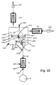
- Fig. 1 shows schematically from the side a cut in a vertical sectional plane Cistern 2, which has a water outlet or outlet connection on the floor 4 with an associated valve 6 contains.
- the valve 6 contains a valve body 8, which is designed here for example as a ball, and one Valve seat 10.
- the valve seat 10 is preferably made of an elastic material, such as rubber or another elastomer, and is in an extension 12 of the the cistern floor 14 molded spout 4 used. Due to the elastic formation of the valve seat 10 is when the valve body 8 the closing process is damped.
- the cistern 2 is not shown here Fasteners connected to or in a wall 16 of a building Integrated pre-wall mounting system or the like.
- the valve body 8 With a brake unit 20 coupled. As shown, the brake unit 20 is by means of a fastener 22 connected to said wall 16 above the cistern 2.
- the brake unit 20 is connected via a further connecting element 24, which again expediently in the form of a cable, with a release unit 26 coupled, which is fastened to the wall 16 via a support 28.
- the trigger unit 26 is arranged in front of the cistern 2, specifically in the area of the front of a line 30 here by means of dash-dotted lines indicated pre-wall mounting system.
- the trigger unit in the Area of the upper edge of the mounting system can be arranged as it is with the reference numeral 26 'is shown.
- the cistern 2 and / or the Brake unit 22 Integrated in the pre-wall mounting system and only with be connected to it.
- the brake unit 22 can within the scope of the invention 20, if necessary, can also be arranged in the upper region of the cistern.
- the trigger unit 26 contains at least one actuating element 32 in the form of a Button 32 or the like to trigger a manual flushing enable.
- the manually operated release unit 26 shown here can also be designed for electrical, hydraulic or other actuation his.
- the trigger unit can enable a dual flush contain another actuator, so that optionally by actuation one or the other actuating element a large quantity flushing or a small quantity flush can be triggered.
- actuation of the actuating element 32 via the bolt 34 of the lever 36 in the direction of arrow 38 onto the further connecting element or the cable 24 a corresponding tensile force for the purpose of rotating a roller 40 of the brake unit 20 be exercised in the direction of arrow 42.
- the further actuating element mentioned can be rotated according to the lever 36, again however, the angle of rotation or the adjustment path for the further connecting element 24 is smaller, for example, in order to be able to trigger a small-volume flush.
- the Trigger unit 20 is via the brake unit 20 and the first connecting element 18 the valve body 8 is raised in the direction of arrow 44 and from the valve seat 10 moved away, so that now the flushing water contained in the cistern 2 can flow out through the outlet nozzle 4.
- the brake unit 20 is designed such that the lowering of the valve body 8 braked in a defined manner and / or delayed in a given time.
- the brake unit 20 has in particular a brake roller 40 which mates with the outer surface of the roller for braking the same acts.
- a single connecting element can also be provided, which as Cable, chain or the like is formed, the by means of the brake unit Defined braking or deceleration of the valve body can be specified.
- the connecting element or cable 18 is expediently a securing unit 46 assigned, which will be explained in more detail below with reference to FIGS. 21 and 22 is explained.
- the connecting element 18 is in one by means of the securing unit lower part, which is coupled to the valve body, and in an overlying Part divided, which is guided on the brake unit 20.
- an elastic coupling of the parts mentioned is effected such that at a sudden quick lifting of the upper part of the connecting element the triggering forces are transmitted to the valve body 8 in an elastically delayed manner. This increases the risk of overstressing, be it the connecting elements or the braking unit or the tripping unit if the pulse-like avoided rapid actuation of the actuator 32.
- the securing unit 46 ' can be arranged between the upper one Release unit 26 ′ or the lateral release unit 26 and the brake unit 20 be arranged.
- FIG. 2 shows the roller 40 in the direction of arrow A according to FIG. 1 with two winding areas 48, 50 for the cable pulls explained above, via which the coupling to Trigger unit or to the valve body.
- the roll 40 also contains one middle area 52, with which a braking element 54 cooperates.
- the braking force that can be predetermined with the braking element 54 thus becomes the rotary movement the roller 40 after triggering a rinsing process and thus the closing movement of said valve body braked.
- the braking element 54 within the scope of the invention also with other zones of Roll 40 can cooperate, for example, in the axial direction according to Art a disc brake.
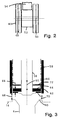
- Fig. 3 shows a further embodiment of the invention, wherein part of the schematic Cistern floor 14 is shown with the outlet nozzle 4.
- a drain set With the cistern is connected in a known manner a drain set, the lower housing part 56th is partially shown in section.
- a valve tube 58 In the drain fitting is a valve tube 58 in the direction of the double arrow 60 movable in the vertical direction.
- the one with the valve tube 58 connected valve body 8 is designed as a valve plate, which after lowering sits on the valve seat 10 of the cistern floor and the outflow of Rinsing water prevents.
- the valve tube 58 with the valve body 8 is in particular can be actuated by means of the trigger unit and brake unit explained above.
- Essential is in this embodiment a useful in the lower housing part 56 of the Drain fitting integrated ring apron 62, which in the raised here shown Position of the valve body 8 surrounds it.
- an attachment element 64 is expediently provided above the valve body 8 or of the valve plate.
- the total height 66 of the valve body 8 expediently in combination with the attachment element 64 is at least approximately the same size as the width 68 of the invention Gap 70 between the lower edge of the housing of the drain fitting and / or the there provided ring apron 62.
- valve tube With dash-dotted lines 59 is an alternative embodiment of the valve tube indicated, whose outer diameter approximately the inner diameter of the Housing part 56 corresponds.
- the valve base mentioned and also the attachment element omitted in this embodiment.
- the valve pipe can be designed in a known manner as an overflow pipe which occurs when the valve is closed or the water supply is disrupted in the cistern water can flow down from the outlet nozzle 4.
- the valve body 8 can also be used instead of the disk-shaped one shown here Geometry have a different geometry.
- Fig. 4 shows in a vertical sectional plane a further embodiment with the Valve body 8 and valve seat 10.
- a flexible sleeve in the flow direction of the water to the outlet nozzle 4 74 arranged.
- the resilient cuff 74 is out of one area 76 surrounded, which with at least one tube 78, 79, line or the like the ambient air is connected or can be connected. That or the pipes 78, 79, lines or the like are conveniently inside the cistern 2 led upwards so that they are above the maximum level of the rinse water end up. The water flows freely during a rinsing process the open valve in the outlet connection 4.
- the valve body 8 is also particularly expedient with an elastic element 80 surrounded such that when sitting on the valve body 10 a delay or a Braking the same takes place.
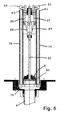
- a further embodiment of the device according to the invention is similar in FIG. 5 that of Fig. 4, with the upper ends 82, 83 of the in the cistern after pipes 78, 79 or lines or the like guided above the maximum Set the water level in the cistern.
- the ends 82, 83 are adjustable by means of arranged closure elements 84, 85 can be closed if necessary.
- the valve body 8 which in turn is an elastic element 80 for delaying the closing process is assigned an adjustment body 86 which is connected to levers 88, 89 interacts to actuate the closure elements 84, 85.
- the closure elements 84, 85 are arranged on two-armed levers 86, 87, the free ends of which Set guides 88, 89 are assigned.
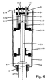
- valve 6 to 8 is a further embodiment with a unit 92 for braking and / or for pressure compensation or a reduction in the pressure difference below of the valve.
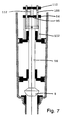
- the valve seat is closed, according to FIG. 7 the valve body 8 is raised such that the upper end of the valve tube 58 by means of a sealing body 94 is closed, and Fig. 8 shows the fully raised Position of the valve body 8 at maximum opening of the valve 6.
- the valve tube 58 is designed as an overflow pipe with a free passage from the upper end 96 up through the valve body 8 into the area 98 below the valve or the outlet nozzle 4.
- the cistern 2 contains guide bodies 100, 101 for the Flushing pipe.
- the guide elements 100, 101 can also in another way with the Cistern 2 may be connected, in particular to the housing of a drain fitting.
- the upper guide elements 101 are together with holding elements 102 of the Sealing body 94 on a support body 104 for connection to the cistern 2 or a waste set or the like.
- 6 is between a gap 106 between the sealing body 94 and the upper end 96 of the valve tube 58 provided so that, if necessary, water through the hollow valve tube 58 inside can flow down into the outlet nozzle 4.
- Fig. 7 closes the upper end 96 of the valve tube 58 by means of the sealing body 94.
- the sealing body 94 is lifted up with and from here as a bolt trained holding elements 102 moved away.
- valve tube 58 With the valve tube 58 is a Holding device 108 connected upwards over the sealing body 94 is guided and carries a support body 110. Between the support body 110 and the a sealing element 94 is provided, by means of which tolerances can be compensated and when lifting the valve pipe an elastically resilient contact of the upper end 96 with the sealing body 94 takes place. Furthermore, by means of the arrangement according to the invention Change in the distance 114 between the sealing body 94 and the support body 110 an exact adjustment of the point at which the closed upper end 96 of the valve tube and in particular when lowering and Closing the valve body is opened again. During the rinsing process the upper end 96 of the valve or overflow pipe 58 closed, so that none Air can be drawn into the area 98 below the valve.
- valve 6 has been fully opened as shown in FIG. 8 during the rinsing process by lowering the valve body 8 and the valve tube 58 of the sealing body 94 again to rest on the holding elements 102, so consequently in a predetermined Period before the valve 6 is completely closed the upper end 96 released.
- valve 6 is completely closed between said lower region 98 and the ambient air or Atmospheric pressure and due to the pressure equalization achieved become disadvantageous Gargle noises when closing the valve 6 avoided or significantly reduced.
- Fig. 9 shows another example of a different design of the geometry of the valve body 8.
- the valve body 8 is as an annular disc, suitably from a suitable Formed sealing material.
- the valve seat 10 is preferably as also in the other embodiments, formed as an annular body, which is inserted into the outlet nozzle 4 from above and preferably also from one suitable sealing material, such as rubber, elastomer or the like.
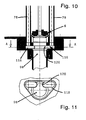
- FIG. 10 and 11 show a special embodiment of the unit 116 or elements for pressure equalization in the area 98 below the valve 6, with FIG. 11 a section along section line A of FIG. 10 shows.
- It is an impact body 118 which is a normally open connection from area 98 the lines or standpipes 78, 79 to the outside, which goes upwards the maximum water level in the cistern.
- the baffle 118 is pot-shaped open at the top and contains an edge 120 such that at open valve 6 water can flow into the impact body 118. The during the The baffle 118, which is filled at times, expediently forms one temporary occlusion by the water rising into line 78, 79.
- the brake unit 122 contains a housing 124, which with the here Cistern not shown and / or a drain set is connected.
- the housing 124 is arranged in the part of the cistern which can be filled with water and is pierced by a rod 126 which connects to the bottom on the one hand with the valve body and on the other hand at the upper end, via others Connecting elements, such as cable, linkage, lever or the like, to the actuating unit enables.
- a piston 128 is provided in the interior of the housing 122, a defined gap 129 being given to the inner wall 130 of the housing 124 is.
- the brake unit 122 is thus a piston-cylinder unit with the Displacement piston 128 formed which the interior of the housing or Cylinder 124 divided into a first chamber 132 and a second chamber 134.
- the Housing 124 and the two chambers 132, 134 contain openings according to FIG. 12 136, 138, to which elastic membranes 140, 142 are assigned. Will be at Triggering the flushing process over the rod 126 of the valve body raised, see above piston 128 is moved upward with water in through openings 136 the lower first chamber 132 flows in while through the upper openings 138 Water is displaced from the second chamber 134.
- bypass connection 144 between in a particularly expedient manner the lower chamber 132 and the upper chamber 134.
- Bypass connection 144 is also provided an adjusting valve 146, by means of which the amount of the lower chamber 132 into the upper chamber 134 as it descends of the piston 128 displaced amount of water can be predetermined in a defined manner.
- an adjusting screw 148 by means of which the passage cross section of the adjustment valve 146 can be predetermined.
- the adjustment valve 146 or the adjustment screw or generally an adjustment element can be operated from the outside, i.e. above the water level of the cistern. So can in a particularly expedient way the rate of descent and ultimately the outflowing amount of flushing water can be set.
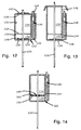
- FIG. 13 shows an embodiment modified in comparison with FIG. 12, that the upper openings 138 of the second chamber 134 are permanently open and only the lower openings 136 by means of the membrane 140 during the Flushing process or when the displacer 128 sinks are closed.
- the upper openings 138 of the second chamber 134 preferably have a large passage cross-section, so that no when lifting the rod 126 significant resistance due to the displacement from the upper chamber 134 Water occurs.
- the embodiment according to FIG. 14 does not contain an opening in the housing 124, but instead the piston 128 is designed as a so-called flutter valve 150 with openings 152, which with a membrane 154 arranged on the side of the first chamber 132 are lockable.
- the openings 152 When triggering a rinsing process, i.e. when lifting the Rod 126 upward, the openings 152 are uncovered while the Sink the openings are closed and the water or generally that Medium through gap 129 from lower chamber 132 to upper chamber 134 is ousted.
- not only that in the cistern can Water can be used as a displacement medium, but also hydraulic oil or air, with the passage of the rod 126 through the Housing 124 is sealed.
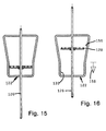
- FIG. 15 and 16 show a special embodiment of the hydraulic or viscous Brake unit similar to that of FIG. 14.
- the housing inner wall is not over the entire length is cylindrical, but is in a predetermined upper part 156, in particular conical, expanded.
- Fig. 15 shows the piston 128 in the Rest position with the cistern valve closed.
- 16 is the raised one Position of the piston 128 shown.
- rod 126 descends from the 16
- the piston 128 then reaches the lower part with the cylindrical inner wall 130, the braking takes place, as explained with the aid of the preceding examples.
- Arrow 158 thus corresponds to the cylindrical inner wall 130 and the assigned piston 128 the braking area is indicated.
- FIG. 17 show an embodiment of the brake unit which does not rigidly the piston connected to the rod 126, but contains a flap valve 160.
- the Flap valve 160 has, expediently two pivotally articulated on the rod 126 Flaps 162, 163 such that when lifting the rod 126 as shown in FIG. 18 the Swing flaps 162, 163 into the first chamber 132.
- the flaps 162, 163 When lowering the bar 126 pivot the flaps 162, 163 upwards in the direction of arrow 164, expediently supported by means of return springs, so that as Flap discs 162, 163 formed in the cylinder half-faces are shown in FIG. 17 To take position.
- the braking is now carried out accordingly above statements. It should be noted at this point that the embodiments 17, 18 as well as those from FIGS. 14, 15, 16 encapsulated to the outside can be formed and with a displacement medium other than water can be operated.
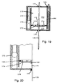
- 19 and 20 show an encapsulated embodiment for any displacement medium, be it water, hydraulic oil, air or the like.
- This brake unit 122 or their housing 124 contains seals 165, 166 for sealing the performed Rod 126.
- a connection line 168 between the first chamber 132 and the second chamber 134 is at least one check valve 170 arranged that when lifting the rod 126, the displacement medium from the second chamber 134 through the connecting line 168 into the first chamber 132 can flow. If necessary, several such check valves 170 can also be used be provided.
- the piston 128 is formed in two parts and contains a first expediently coupled to the rod 126 via a spring 171 first, in particular plate-shaped part 172.
- a second part 174 is assigned to the first part 172, which is fixed to the rod 126 and the openings 176 by means of of the first substantially rigid part 172 are closable.
- a seal 178 is provided for second part 174.
- the inner wall 130 of the housing 124 is provided with a seal 180.
- the first piston part 172 arranged axially movable on the rod 126 and a further seal 181 is provided for the rod 126.
- the first piston part 172 coupled via the spring 171 becomes counter to the Spring force pushed away from the second piston part 174 and the mutual sealing canceled.
- the medium can thus leave the second chamber practically unhindered 134 through the comparatively large openings 176 into the first chamber 132 stream.
- the check valve 170 the connecting line 168 closed.
- the first piston part 172 again close to the second piston part 174, wherein by means of said seal 178 a functionally reliable Sealing is guaranteed.
- the displacement medium can be removed from the lower first chamber 132 through the bypass connection 144 and the adjustment valve 146 flow into the upper second chamber 134, whereby the Lowering speed of the rod 126 and thus the valve body is predetermined.
- the rate of descent by means of of the bypass adjustment valve 146 can be predetermined.
- the Adjustment of the adjustment valve 146 in the context of the invention also from the outside, for example can be made via a Bowden cable or the like.
- the externally hermetically sealed embodiment according to FIGS. 19 and 20 enables the piston to be blocked in a particularly expedient manner descending of the rod 126.
- the Adjustment valve 146 blocked, so the medium can no longer leave the first chamber 132 flow into the second chamber 134.
- the adjustment valve 146 blocked position of the rod 126 easily service work, for example the valve.
- FIG. 21 shows a further, special embodiment of the brake unit 182, which as Security unit is formed and the security unit shown in Fig. 1 corresponds, with a housing 184 and a rod 186, with which the valve body 8 is coupled.
- a spring 188 is provided in the housing 184 in the housing 184, on which the Rod 186 is supported.
- Connection body 190 is provided, via which the connection to the release unit, for example via a cable, another rod, lever or the like can be produced.
- FIG. 22 shows in a schematic representation different possibilities of Positioning of the brake unit 182.
- the rod is 186 coupled to a further brake unit 192, while the housing according to arrow 194 is coupled to the release unit, which for example on a vertical Wall of a pre-wall mounting system is arranged.
- the release unit which for example on a vertical Wall of a pre-wall mounting system is arranged.
- the connection to a release unit can be established, which is arranged horizontally.
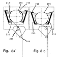
- the brake unit 192 contains a brake roller similar to the embodiment of FIG. 1 196, which is movably mounted in the housing 200 by means of a slide 198.
- the Brake unit 192 has, in particular in the housing 200, guides 201 for the Sled 198 on.
- the guides 201 are designed such that the slide 198 is movable parallel to its position shown here and tilting movements be avoided.
- 198 for the parallel movement of the carriage preferably three such guides 201 are provided in the form of slots in the housing.
- Corresponding guides and slots are also on the behind the Back of the housing 200 for drawing bars or other lying in the drawing plane Elements of the carriage 198 partially penetrating the housing 200 are provided.
- a lever 202 which is about an axis 203, is coupled to the slide 198 is pivotally mounted.
- the lever 202 acts on the via an eccentric 204 Carriage 198 that when the lever 202 is pivoted in the direction of arrow 205 the carriage 198 with the brake roller 196 in the direction of arrow 206 upwards is raised.
- a roller 207 is provided over which the Seizug 18 is guided.
- a guide role 208 for the Cable 18 arranged on the housing 200 such that the valve body 8 is always exact is guided over the valve seat.
- the housing 200 contains a link guide 210 for movable Support body 212, 213, which are connected to said carriage 198. Between the brake roller 196 over which the cable 18 is guided, and the Support bodies 212, 213 are spring elements 214, 215 and also brake bodies 216 intended.
- the brake roller 196 After triggering and during the flushing process, the brake roller 196 takes the 25 a lower position in the link guide 210, the Spring elements 214, 215 are tensioned and ultimately the required braking force on the brake roller 196 is effective. Due to the common bearing of the brake roller 196 and the two support bodies on the said carriage and its Parallel guidance when lifting is combined with the link guidance immediate braking after triggering the rinsing process ensured.
Landscapes
- Engineering & Computer Science (AREA)
- Mechanical Engineering (AREA)
- Aviation & Aerospace Engineering (AREA)
- Health & Medical Sciences (AREA)
- Life Sciences & Earth Sciences (AREA)
- Hydrology & Water Resources (AREA)
- Public Health (AREA)
- Water Supply & Treatment (AREA)
- Lift Valve (AREA)
- Sanitary Device For Flush Toilet (AREA)
Abstract
Description
- Fig. 1
- eine schematische Darstellung eines ersten Ausführungsbeispiels der erfindungsgemäßen Vorrichtung,
- Fig. 2
- eine Ansicht der Rolle der Bremseinheit in Blickrichtung A gemäß Fig. 1,
- Fig. 3
- vergrößert ein weiteres Ausführungsbeispiel mit einer dem Ventilkörper zugeordneten Ringschürze,
- Fig. 4
- ein Ausführungsbeispiel der erfindungsgemäßen Vorrichtung mit einer Luftbremse,
- Fig. 5
- ein Ausführungsbeispiel, welches kurz vor dem Ende des Spülvorgangs eine Luftzufuhr in den Bereich unterhalb des Ventils ermöglicht,
- Fig. 6 - 8
- ein Ausführungsbeispiel mit einer Vorrichtung zum Verschließen des mit dem Ventilkörper gekoppelten Überlaufrohres und Freigabe in einem definierten Zeitraum vor dem Schließen des Ventils,
- Fig. 9
- eine alternative Ausgestaltung des Ventilkörpers,
- Fig. 10, 11
- ein Ausführungsbeispiel mit einem unterhalb des Ventils angeordneten Prallkörper zum Verschließen und Freigeben einer Leitung zwecks Druckausgleich vor dem Schließen des Ventils,
- Fig. 12 - 20
- Ausführungsformen mit hydraulischen Bremsen,
- Fig. 21 - 25
- Ausführungsformen mit mechanischen Bremsen.
- 2
- Spülkasten
- 4
- Auslaufstutzen
- 6
- Ventil
- 8
- Ventilkörper
- 10
- Ventilsitz
- 12
- Erweiterung
- 14
- Spülkastenboden
- 16
- Wand
- 18
- Verbindungselement / Seilzug
- 20
- Bremseinheit
- 22
- Befestigungselement
- 24
- weiteres Verbindungselement
- 26
- Auslöseeinheit
- 28
- Träger
- 30
- strichpunktierte Linie / Vorwand-Installationssystem
- 32
- Betätigungselement
- 34
- Bolzen
- 36
- Hebel
- 38
- Pfeil
- 40
- Rolle
- 42, 44
- Pfeil
- 46
- Sicherungseinheit
- 48, 50
- Wickelbereich
- 52
- mittlerer Bereich
- 54
- Bremselement
- 56
- Gehäuseteil einer Ablaufgarnitur
- 58, 59
- Ventilrohr
- 60
- Doppelpfeil
- 62
- Ringschürze
- 64
- Aufsatzelement
- 66
- Gesamthöhe
- 68
- Breite
- 70
- Spalt
- 72
- Ventilboden
- 74
- Manschette
- 76
- Bereich
- 78, 79
- Rohr / Leitung
- 80
- elastisches Element
- 82, 83
- Ende von 78, 79
- 84, 85
- Verschlußelement
- 86, 87
- Hebel
- 88, 89
- Kulissenführung
- 90
- Stange
- 92
- Einheit
- 94
- Abdichtkörper
- 96
- oberes Ende von 58
- 98
- Bereich unterhalb von 6
- 100, 101
- Führungselement
- 102
- Halteelement
- 104
- Tragkörper
- 106
- Spalt
- 108
- Haltevorrichtung
- 110
- Stützkörper
- 112
- Federelement
- 114
- Abstand
- 116
- Einheit
- 118
- Prallkörper
- 120
- Rand von 118
- 122
- hydraulische Bremseinheit
- 124
- Gehäuse / Zylinder
- 126
- Stange
- 128
- Kolben
- 129
- Spalt
- 130
- Innenwand von 124
- 132
- erste Kammer von 124
- 134
- zweite Kammer von 124
- 136, 138
- Öffnungen
- 140, 142
- Membran
- 144
- Bypass-Verbindung
- 146
- Einstellventil
- 148
- Einstellschraube
- 150
- Flatterventil
- 152
- Öffnung
- 154
- Membran
- 156
- oberer Teil
- 158
- Pfeil
- 160
- Klappenventil
- 162, 163
- Klappe
- 164
- Pfeil
- 165, 166
- Dichtung
- 168
- Verbindungsleitung
- 170
- Rückschlagventil
- 171
- Feder
- 172
- erster Teil
- 174
- zweiter Teil
- 176
- Öffnung
- 178
- Dichtung
- 180, 181
- Dichtung
- 182
- Bremseinheit
- 184
- Gehäuse
- 186
- Stange
- 188
- Feder
- 190
- Verbindungskörper
- 192
- Bremseinheit
- 194, 195
- Pfeil
- 196
- Bremsrolle
- 198
- Schlitten
- 200
- Gehäuse
- 201
- Führung
- 202
- Hebel
- 203
- Achse
- 204
- Excenter
- 205, 206
- Pfeil
- 207
- Rolle
- 208
- Führung
- 209
- Rückstellfeder
- 210
- Kulissenführung
- 212, 213
- Stützkörper
- 214, 215
- Federelement
- 216
- Bremskörper
Claims (12)
- Vorrichtung zur Betätigung eines Ventils (6) eines Spülkastens, dessen Wasserauslauf mittels des Ventils (6) absperrbar und durch Auslösen eines Spülvorganges freigebbar ist, wobei wenigstens ein Verbindungselement (18, 24, 126) zur Betätigung des Ventils (6) vorgesehen ist,
dadurch gekennzeichnet, daß dem Verbindungselement (18, 24, 126) oder dem Ventil (6) eine Bremseinheit (20, 92, 116, 122, 182, 192) zugeordnet ist. - Vorrichtung nach Anspruch 1, dadurch gekennzeichnet, daß die Bremseinheit (20, 92, 116, 122, 182, 192) zwischen dem Ventilkörper (8) und einer Auslöseeinheit (26) angeordnet ist und/oder daß die Bremseinheit (20, 192) eine Bremsrolle (40, 196) enthält, welche dem wenigstens einen Verbindungselement (18, 24) zugeordnet ist,
- Vorrichtung nach Anspruche 2, dadurch gekennzeichnet, daß das erste Verbindungselement (24) einerseits mit einer Auslöseeinheit (26) und andererseits mit der Rolle (40) gekoppelt ist, und daß ferner das zweite Verbindungselement (18) einerseits mit der Rolle (40) und andererseits mit dem Ventilkörper (8) gekoppelt ist.
- Vorrichtung nach einem der Ansprüche 1 bis 3, dadurch gekennzeichnet, daß die Bremseinheit (192) eine bewegbar angeordnete Bremsrolle (196) derart aufweist, daß beim Auslösen des Spülvorganges und Anheben des Ventilkörpers (8) die Bremswirkung aufgehoben, zumindest aber wesentlich reduziert ist und/oder daß die Bremsrolle (196) auf einem Schlitten (198) bewegbar angeordnet ist und/oder daß die insbesondere über einen Bremskörper (216) wirksame Bremskraft beim Auslösen zumindest wesentlich reduziert ist.
- Vorrichtung nach einem der Ansprüche 1 bis 4, dadurch gekennzeichnet, daß der Ventilkörper (8) federelastisch ausgebildet ist und / oder ein federelastisches Element (80) enthält, und / oder daß der Ventilsitz (10) zumindest teilweise federelastisch ausgebildet ist.
- Vorrichtung, insbesondere nach einem der Ansprüche 1 bis 5, dadurch gekennzeichnet, daß eine mit dem Spülkasten (2) verbundene Ablaufgarnitur am unteren Ende eine Ringschürze (62) aufweist, welche in der geöffneten Stellung des Ventils den Ventilkörper (8) umgibt, wobei oberhalb des Ventilkörpers (8) ein Ventilboden (72) vorgesehen ist, und daß der Ventilkörper (8), insbesondere mit einem über demselben angeordneten Aufsatzelement (64) eine Gesamthöhe (66) aufweist, welche zumindest näherungsweise gleich groß ist wie die Breite (68) eines Spaltes (70) zwischen der Ringschürze (62) und dem Spülkastenboden (14).
- Vorrichtung, insbesondere nach einem der Ansprüche 1 und 6, dadurch gekennzeichnet, daß eine Einheit (92) für den Druckausgleich unterhalb des Ventils (6) derart vorgesehen ist, daß insbesondere in einem vorgebbaren Zeitraum vor dem Schließen des Ventils (6) der Druckausgleich oder zumindest eine Reduzierung der Druckdifferenz des Drucks in einem Bereich (98) unterhalb des Ventils (6) zum Atmosphärendruck erfolgt
- Vorrichtung nach einem der Ansprüche 1 bis 7, dadurch gekennzeichnet, daß unterhalb des Ventilsitzes (10) ein Bereich (76, 98) vorgesehen ist, welcher über wenigstens ein Rohr (78, 79), Leitung oder dergleichen mit der Umgebungsluft in Verbindung steht oder verbindbar ist, und / oder daß das Rohr (78, 79), Leitung oder dergleichen mit seinem freien Ende (82, 83) zumindest bis zum maximalen Spülwasserstand im Inneren des Spülkastens (2) nach oben geführt ist.
- Vorrichtung nach Anspruch 7 oder 8, dadurch gekennzeichnet, daß der Bereich (76) von einer radial innenliegenden elastischen Manschette (74) begrenzt ist, welche innen die Verbindung zwischen dem Ventilsitz (10) und dem Auslaufstutzen (4) bildet, und/oder daß dem oberen Ende (82, 83) ein Verschlußelement (84, 85) zugeordnet ist, welches mittels eines mit dem Ventilkörper (8) verbundenen Hebels (86, 87) zum Schließen oder Öffnen der Enden (82, 83) des Rohres (78, 79), Leitungen oder dergleichen vorgesehen ist.
- Vorrichtung nach einem der Ansprüche 7 bis 9, dadurch gekennzeichnet, daß dem oberen Ende (96) eines Ventilrohres (58) eine Einheit (92) zugeordnet ist, mittels welcher das obere Ende (96) in einem vorgegebenen Zeitraum vor dem Schließen des Ventils (6) freigebbar ist und/oder daß die Einheit (92) einen Abdichtkörper (94) enthält, wobei - abgesehen von dem vorgegebenen Zeitraum vor dem Schließen des Ventils (6) - zwischen dem Abdichtkörper (94) und dem oberen Ende (96) des Spülrohres ein Spalt (106) vorgegeben ist.
- Vorrichtung nach einem der Ansprüche 7 bis 10, dadurch gekennzeichnet, daß dem Bereich (98) unterhalb des Ventils eine Einheit (116) zugeordnet ist, mittels welcher in einem vorgegebenen Zeitraum vor dem Schließen des Ventils eine Verbindung des Bereiches (98) über eine Leitung (78, 79) nach außen zur Umgebungsluft herstellbar ist, und/oder daß die Einheit (116) einen Prallkörper (118) derart aufweist, daß dieser Prallkörper (118) zeitweise mit Wasser gefüllt ist.
- Vorrichtung nach einem der Ansprüche 1 bis 11, dadurch gekennzeichnet, daß die Bremseinheit (122) einen Verdrängerkolben enthält, welcher vorzugsweise mit einer mit dem Ventilkörper (8) verbundenen Stange (126) gekoppelt ist, und/oder daß die Bremseinheit (122) eine Bypassleitung zwischen den beiden Kammern (132, 134), insbesondere mit einem Einstellventil (146) aufweist und/oder daß der Bremsrolle (196) eine Führung, insbesondere eine Kulissenführung (210) zugeordnet ist, und/oder daß beim Auslösen des Spülvorganges, insbesondere durch Anheben der Bremsrolle (196) mittels des Schlittens (198) und eines Hebels (202), Federelemente (214, 215) entspannt werden, welche auf die Bremsrolle (196) einwirken.
Applications Claiming Priority (4)
| Application Number | Priority Date | Filing Date | Title |
|---|---|---|---|
| DE19903228 | 1999-01-27 | ||
| DE19903228 | 1999-01-27 | ||
| DE19914841 | 1999-04-01 | ||
| DE19914841A DE19914841A1 (de) | 1999-01-27 | 1999-04-01 | Vorrichtung zur Betätigung des Ventils eines Spülkastens |
Publications (2)
| Publication Number | Publication Date |
|---|---|
| EP1024230A2 true EP1024230A2 (de) | 2000-08-02 |
| EP1024230A3 EP1024230A3 (de) | 2002-08-21 |
Family
ID=26051513
Family Applications (1)
| Application Number | Title | Priority Date | Filing Date |
|---|---|---|---|
| EP00100315A Withdrawn EP1024230A3 (de) | 1999-01-27 | 2000-01-07 | Vorrichtung zur Betätigung des Ventils eines Spülkastens |
Country Status (2)
| Country | Link |
|---|---|
| EP (1) | EP1024230A3 (de) |
| PL (1) | PL338099A1 (de) |
Cited By (1)
| Publication number | Priority date | Publication date | Assignee | Title |
|---|---|---|---|---|
| EP2505727A1 (de) * | 2011-03-30 | 2012-10-03 | Geberit International AG | Ablaufventil für einen Spülkasten |
Citations (1)
| Publication number | Priority date | Publication date | Assignee | Title |
|---|---|---|---|---|
| EP0503177A1 (de) | 1991-03-12 | 1992-09-16 | PLASSON MAAGAN MICHAEL INDUSTRIES Limited | Stossdämpfungsvorrichtung für Ablaufventilmechanismus |
Family Cites Families (4)
| Publication number | Priority date | Publication date | Assignee | Title |
|---|---|---|---|---|
| GB501205A (en) * | 1937-08-23 | 1939-02-23 | James Allan Barclay | Improvements relating to water waste preventors |
| DE1914064A1 (de) * | 1969-03-20 | 1971-06-16 | Rost & Soehne Georg | Ablaufventil fuer Spuelkaesten |
| US4080668A (en) * | 1977-02-16 | 1978-03-28 | The Raymond Lee Organization, Inc. | Dual toilet flushing system |
| US4587679A (en) * | 1984-12-05 | 1986-05-13 | Chen Chin Lin | Toilet flushing device |
-
2000
- 2000-01-07 EP EP00100315A patent/EP1024230A3/de not_active Withdrawn
- 2000-01-27 PL PL33809900A patent/PL338099A1/xx not_active Application Discontinuation
Patent Citations (1)
| Publication number | Priority date | Publication date | Assignee | Title |
|---|---|---|---|---|
| EP0503177A1 (de) | 1991-03-12 | 1992-09-16 | PLASSON MAAGAN MICHAEL INDUSTRIES Limited | Stossdämpfungsvorrichtung für Ablaufventilmechanismus |
Cited By (1)
| Publication number | Priority date | Publication date | Assignee | Title |
|---|---|---|---|---|
| EP2505727A1 (de) * | 2011-03-30 | 2012-10-03 | Geberit International AG | Ablaufventil für einen Spülkasten |
Also Published As
| Publication number | Publication date |
|---|---|
| EP1024230A3 (de) | 2002-08-21 |
| PL338099A1 (en) | 2000-07-31 |
Similar Documents
| Publication | Publication Date | Title |
|---|---|---|
| EP2865817B1 (de) | Ablaufgarnitur für einen Spülkasten | |
| DE1904460A1 (de) | Spuelkastenfuellventil | |
| DE69832042T2 (de) | Absperrfülventil | |
| DE2612556A1 (de) | Schwimmerventil fuer eine wasserspuelung | |
| EP3551808A1 (de) | Druckwasserventil | |
| DE102007001718A1 (de) | Ablaufventil mit einstellbarer Vollspülmenge | |
| EP0145773A1 (de) | Wc - spülkasten | |
| EP2092128B1 (de) | Zwei-mengen-ablaufventil | |
| DE9215972U1 (de) | Spülkasten-Ablaufventil | |
| EP3467215B1 (de) | Ablaufgarnitur | |
| DE10002308C2 (de) | WC-Spülkasten | |
| EP1024230A2 (de) | Vorrichtung zur Betätigung des Ventils eines Spülkastens | |
| EP3321431B1 (de) | Ablaufgarnitur | |
| DE19914841A1 (de) | Vorrichtung zur Betätigung des Ventils eines Spülkastens | |
| EP4095325B1 (de) | Füllventil | |
| EP0503209B1 (de) | Regelvorrichtung zur Veränderung des Durchflussquerschnitts der Auslauföffnung eines Ausgleichsbehälters, insbesondere eines Regenrückhaltebeckens | |
| EP2505727B1 (de) | Ablaufventil für einen Spülkasten | |
| WO2014124788A1 (de) | Ablaufgarnitur für einen spülkasten | |
| DE102004029186B4 (de) | Vorrichtung zum kontrollierten Öffnen und Schließen eines mit einem Toilettenbecken im Bereich einer Lagerung gelenkig verbundenen Toilettendeckels | |
| EP1270831B1 (de) | Ablaufventil für einen Spülkasten | |
| DE19735592C2 (de) | Vorrichtung zum Betätigen eines Mechanismus einer Spüleinrichtung | |
| EP1580338B1 (de) | Ablaufarmatur für einen Spülkasten | |
| EP3538716B1 (de) | Ablaufgarnitur | |
| EP4095327B1 (de) | Spülventil | |
| DE8524447U1 (de) | Pneumatische Steuervorrichtung für ein Absperrventil einer Vakuum-Abwasserleitung |
Legal Events
| Date | Code | Title | Description |
|---|---|---|---|
| PUAI | Public reference made under article 153(3) epc to a published international application that has entered the european phase |
Free format text: ORIGINAL CODE: 0009012 |
|
| AK | Designated contracting states |
Kind code of ref document: A2 Designated state(s): AT BE CH CY DE DK ES FI FR GB GR IE IT LI LU MC NL PT SE |
|
| AX | Request for extension of the european patent |
Free format text: AL;LT;LV;MK;RO;SI |
|
| PUAL | Search report despatched |
Free format text: ORIGINAL CODE: 0009013 |
|
| AK | Designated contracting states |
Kind code of ref document: A3 Designated state(s): AT BE CH CY DE DK ES FI FR GB GR IE IT LI LU MC NL PT SE |
|
| AX | Request for extension of the european patent |
Free format text: AL;LT;LV;MK;RO;SI |
|
| 17P | Request for examination filed |
Effective date: 20030120 |
|
| 17Q | First examination report despatched |
Effective date: 20030311 |
|
| AKX | Designation fees paid |
Designated state(s): AT BE CH CY DE DK ES FI FR GB GR IE IT LI LU MC NL PT SE |
|
| STAA | Information on the status of an ep patent application or granted ep patent |
Free format text: STATUS: THE APPLICATION IS DEEMED TO BE WITHDRAWN |
|
| 18D | Application deemed to be withdrawn |
Effective date: 20030923 |