EP1024210B1 - Apparatus and method for producing tungsten nitride film - Google Patents
Apparatus and method for producing tungsten nitride film Download PDFInfo
- Publication number
- EP1024210B1 EP1024210B1 EP00100937A EP00100937A EP1024210B1 EP 1024210 B1 EP1024210 B1 EP 1024210B1 EP 00100937 A EP00100937 A EP 00100937A EP 00100937 A EP00100937 A EP 00100937A EP 1024210 B1 EP1024210 B1 EP 1024210B1
- Authority
- EP
- European Patent Office
- Prior art keywords
- gas
- film
- jetted
- feedstock
- reactor
- Prior art date
- Legal status (The legal status is an assumption and is not a legal conclusion. Google has not performed a legal analysis and makes no representation as to the accuracy of the status listed.)
- Expired - Lifetime
Links
Images
Classifications
-
- C—CHEMISTRY; METALLURGY
- C23—COATING METALLIC MATERIAL; COATING MATERIAL WITH METALLIC MATERIAL; CHEMICAL SURFACE TREATMENT; DIFFUSION TREATMENT OF METALLIC MATERIAL; COATING BY VACUUM EVAPORATION, BY SPUTTERING, BY ION IMPLANTATION OR BY CHEMICAL VAPOUR DEPOSITION, IN GENERAL; INHIBITING CORROSION OF METALLIC MATERIAL OR INCRUSTATION IN GENERAL
- C23C—COATING METALLIC MATERIAL; COATING MATERIAL WITH METALLIC MATERIAL; SURFACE TREATMENT OF METALLIC MATERIAL BY DIFFUSION INTO THE SURFACE, BY CHEMICAL CONVERSION OR SUBSTITUTION; COATING BY VACUUM EVAPORATION, BY SPUTTERING, BY ION IMPLANTATION OR BY CHEMICAL VAPOUR DEPOSITION, IN GENERAL
- C23C16/00—Chemical coating by decomposition of gaseous compounds, without leaving reaction products of surface material in the coating, i.e. chemical vapour deposition [CVD] processes
- C23C16/44—Chemical coating by decomposition of gaseous compounds, without leaving reaction products of surface material in the coating, i.e. chemical vapour deposition [CVD] processes characterised by the method of coating
- C23C16/455—Chemical coating by decomposition of gaseous compounds, without leaving reaction products of surface material in the coating, i.e. chemical vapour deposition [CVD] processes characterised by the method of coating characterised by the method used for introducing gases into reaction chamber or for modifying gas flows in reaction chamber
- C23C16/45563—Gas nozzles
- C23C16/45565—Shower nozzles
-
- H—ELECTRICITY
- H10—SEMICONDUCTOR DEVICES; ELECTRIC SOLID-STATE DEVICES NOT OTHERWISE PROVIDED FOR
- H10P—GENERIC PROCESSES OR APPARATUS FOR THE MANUFACTURE OR TREATMENT OF DEVICES COVERED BY CLASS H10
- H10P14/00—Formation of materials, e.g. in the shape of layers or pillars
- H10P14/20—Formation of materials, e.g. in the shape of layers or pillars of semiconductor materials
-
- C—CHEMISTRY; METALLURGY
- C23—COATING METALLIC MATERIAL; COATING MATERIAL WITH METALLIC MATERIAL; CHEMICAL SURFACE TREATMENT; DIFFUSION TREATMENT OF METALLIC MATERIAL; COATING BY VACUUM EVAPORATION, BY SPUTTERING, BY ION IMPLANTATION OR BY CHEMICAL VAPOUR DEPOSITION, IN GENERAL; INHIBITING CORROSION OF METALLIC MATERIAL OR INCRUSTATION IN GENERAL
- C23C—COATING METALLIC MATERIAL; COATING MATERIAL WITH METALLIC MATERIAL; SURFACE TREATMENT OF METALLIC MATERIAL BY DIFFUSION INTO THE SURFACE, BY CHEMICAL CONVERSION OR SUBSTITUTION; COATING BY VACUUM EVAPORATION, BY SPUTTERING, BY ION IMPLANTATION OR BY CHEMICAL VAPOUR DEPOSITION, IN GENERAL
- C23C16/00—Chemical coating by decomposition of gaseous compounds, without leaving reaction products of surface material in the coating, i.e. chemical vapour deposition [CVD] processes
- C23C16/22—Chemical coating by decomposition of gaseous compounds, without leaving reaction products of surface material in the coating, i.e. chemical vapour deposition [CVD] processes characterised by the deposition of inorganic material, other than metallic material
- C23C16/30—Deposition of compounds, mixtures or solid solutions, e.g. borides, carbides, nitrides
- C23C16/34—Nitrides
-
- C—CHEMISTRY; METALLURGY
- C23—COATING METALLIC MATERIAL; COATING MATERIAL WITH METALLIC MATERIAL; CHEMICAL SURFACE TREATMENT; DIFFUSION TREATMENT OF METALLIC MATERIAL; COATING BY VACUUM EVAPORATION, BY SPUTTERING, BY ION IMPLANTATION OR BY CHEMICAL VAPOUR DEPOSITION, IN GENERAL; INHIBITING CORROSION OF METALLIC MATERIAL OR INCRUSTATION IN GENERAL
- C23C—COATING METALLIC MATERIAL; COATING MATERIAL WITH METALLIC MATERIAL; SURFACE TREATMENT OF METALLIC MATERIAL BY DIFFUSION INTO THE SURFACE, BY CHEMICAL CONVERSION OR SUBSTITUTION; COATING BY VACUUM EVAPORATION, BY SPUTTERING, BY ION IMPLANTATION OR BY CHEMICAL VAPOUR DEPOSITION, IN GENERAL
- C23C16/00—Chemical coating by decomposition of gaseous compounds, without leaving reaction products of surface material in the coating, i.e. chemical vapour deposition [CVD] processes
- C23C16/44—Chemical coating by decomposition of gaseous compounds, without leaving reaction products of surface material in the coating, i.e. chemical vapour deposition [CVD] processes characterised by the method of coating
- C23C16/4401—Means for minimising impurities, e.g. dust, moisture or residual gas, in the reaction chamber
-
- C—CHEMISTRY; METALLURGY
- C23—COATING METALLIC MATERIAL; COATING MATERIAL WITH METALLIC MATERIAL; CHEMICAL SURFACE TREATMENT; DIFFUSION TREATMENT OF METALLIC MATERIAL; COATING BY VACUUM EVAPORATION, BY SPUTTERING, BY ION IMPLANTATION OR BY CHEMICAL VAPOUR DEPOSITION, IN GENERAL; INHIBITING CORROSION OF METALLIC MATERIAL OR INCRUSTATION IN GENERAL
- C23C—COATING METALLIC MATERIAL; COATING MATERIAL WITH METALLIC MATERIAL; SURFACE TREATMENT OF METALLIC MATERIAL BY DIFFUSION INTO THE SURFACE, BY CHEMICAL CONVERSION OR SUBSTITUTION; COATING BY VACUUM EVAPORATION, BY SPUTTERING, BY ION IMPLANTATION OR BY CHEMICAL VAPOUR DEPOSITION, IN GENERAL
- C23C16/00—Chemical coating by decomposition of gaseous compounds, without leaving reaction products of surface material in the coating, i.e. chemical vapour deposition [CVD] processes
- C23C16/44—Chemical coating by decomposition of gaseous compounds, without leaving reaction products of surface material in the coating, i.e. chemical vapour deposition [CVD] processes characterised by the method of coating
- C23C16/455—Chemical coating by decomposition of gaseous compounds, without leaving reaction products of surface material in the coating, i.e. chemical vapour deposition [CVD] processes characterised by the method of coating characterised by the method used for introducing gases into reaction chamber or for modifying gas flows in reaction chamber
- C23C16/45514—Mixing in close vicinity to the substrate
-
- C—CHEMISTRY; METALLURGY
- C23—COATING METALLIC MATERIAL; COATING MATERIAL WITH METALLIC MATERIAL; CHEMICAL SURFACE TREATMENT; DIFFUSION TREATMENT OF METALLIC MATERIAL; COATING BY VACUUM EVAPORATION, BY SPUTTERING, BY ION IMPLANTATION OR BY CHEMICAL VAPOUR DEPOSITION, IN GENERAL; INHIBITING CORROSION OF METALLIC MATERIAL OR INCRUSTATION IN GENERAL
- C23C—COATING METALLIC MATERIAL; COATING MATERIAL WITH METALLIC MATERIAL; SURFACE TREATMENT OF METALLIC MATERIAL BY DIFFUSION INTO THE SURFACE, BY CHEMICAL CONVERSION OR SUBSTITUTION; COATING BY VACUUM EVAPORATION, BY SPUTTERING, BY ION IMPLANTATION OR BY CHEMICAL VAPOUR DEPOSITION, IN GENERAL
- C23C16/00—Chemical coating by decomposition of gaseous compounds, without leaving reaction products of surface material in the coating, i.e. chemical vapour deposition [CVD] processes
- C23C16/44—Chemical coating by decomposition of gaseous compounds, without leaving reaction products of surface material in the coating, i.e. chemical vapour deposition [CVD] processes characterised by the method of coating
- C23C16/455—Chemical coating by decomposition of gaseous compounds, without leaving reaction products of surface material in the coating, i.e. chemical vapour deposition [CVD] processes characterised by the method of coating characterised by the method used for introducing gases into reaction chamber or for modifying gas flows in reaction chamber
- C23C16/45563—Gas nozzles
- C23C16/4558—Perforated rings
Definitions
- This invention relates to the technical field of forming metal nitrides. More particularly, it provides a technique adequate for forming tungsten nitride films.
- titanium nitride films are formed as barrier films at the interface between the aluminum films and silicon substrates.
- these titanium nitride films are poor in the ability to prevent the diffusion of copper.
- W x N films tungsten nitride films
- Patent Abstracts of Japan, vol. 16, no. 55 describes the manufacture of a semi-conductor device wherein a tungsten nitride film is formed on a coated silicon substrate. It is essential that two gases such as nitrogen and oxygen are introduced from the first gas feed pipe while tungsten hexafluoride is introduced from the second gas feed pipe.
- a substrate 120 on which a W x N film and a copper film are to be formed, consists of a silicon substrate 150, a silicon oxide film 152 formed on the silicon substrate 150 and a pore 160 formed in the silicon oxide film 152.
- a reactor 111 is first evacuated. Then the substrate 120 is carried thereinto and placed on a holder 114 provided in the bottom side of the reactor 111.
- a shower nozzle 112 is provided in the ceiling side of the reactor 111.
- two types of feedstock gases for example, WF 6 gas and NH 3 gas
- WF 6 gas and NH 3 gas are jetted from the shower nozzle 112 toward the substrate 120 as shown by arrows 151, thereby inducing the following chemical reaction: 4WF 6 + 8NH 3 ⁇ 2W 2 N + 24HF + 3N 2 .
- a W x N film 153 is formed on the surface of the substrate 120 as shown in Fig. 5(b), wherein X is referred tentatively as to 2.
- the substrate 120 is taken out from the reactor 111. Then a copper film 154 is formed on the W x N film 153 as shown in Fig. 5 (c) and followed by the transportation to the subsequent stage, i.e., the patterning of the copper film 154, etc.
- the substrate 120 can be continuously treated without exposing to the atmosphere by connecting a apparatus for forming a tungsten film and a apparatus for forming a copper film to a multi-chamber type apparatus.
- the above-described reactor 111 of the prior art suffers from another problem of a low growth speed of the W x N film. Thus, it has been required to clarify the cause of this phenomenon and to establish a countermeasure effective therefor.
- the present invention which has been made to overcome the above-described problems encountering in the prior art, aims at providing a technique for forming a tungsten nitride film without causing dusting, and a technique for forming a tungsten nitride film showing a high growth speed.
- the present invention relates to a method for producing a tungsten nitride film using a film forming apparatus provided with an evacuatable reactor, an adhesion preventive container placed in said reactor, a holder whereby a object on which the film is to be formed is located in said adhesion preventive container, a first gas inlet equipment which faces to said holder and constructed so that it can jet a gas into said adhesion preventive container, and a second gas inlet equipment which is constructed so that it can jet a gas between said first gas inlet equipment and said holder.
- the film forming apparatus is constructed so that, in said adhesion preventive container, at least the part around said material on which the film is to be formed is maintained at a temperature of 150 to 300°C.
- the film forming apparatus comprising said first gas inlet equipment has a shower nozzle provided with a number of gas jet orifices formed on the almost same plane.
- the film forming apparatus comprising said second gas inlet equipment has a nozzle made of a hollow pipe shaped into a ring and a number of gas jet orifices are formed in said hollow pipe.
- the present invention relates to a method for producing a tungsten nitride film which comprises jetting a first NH 3 feedstock gas and a second WF 6 feedstock gas into a reactor and reacting said first feedstock gas with said second feedstock gas so as to form a tungsten nitride film on the surface of a material on which the film is to be formed, wherein the distance between the position from which said first feedstock gas is jetted and the surface of said material on which the film is to be formed is different from the distance between the position from which said second feedstock gas is jetted and the surface of said material on which the film is to be formed.
- the present invention relates to the method for producing a tungsten nitride film which comprises providing an adhesion preventive container in said reactor and placing said object on which a film is to be formed in the adhesion preventive container; heating, in said adhesion preventive container, at least the part around said material on which the film is to be formed to a temperature of preferably 150 to 250°C; and jetting said first feedstock gas and second feedstock gas into said adhesion preventive container.
- the present invention relates to the method for producing a tungsten nitride film, wherein one of said first feedstock gas and second feedstock gas is jetted downward in the vertical direction toward the surface of said object on which a film is to be formed.
- the present invention relates to the method for producing a tungsten nitride film, wherein, between said first feedstock gas and second feedstock gas, the one gas jetted from the lower position is jetted sideways toward center of said object on which a film is to be formed.
- the film forming apparatus used in the method according to the present invention which has the constitution as described above, has an adhesion preventive container placed in the reactor.
- a holder is provided so that a object on which a film is to be formed (i.e., the substrate) can be hold in the adhesion preventive container.
- This film forming apparatus is provided with a first gas inlet equipment and a second gas inlet equipment through which feedstock gases are respectively jetted into the adhesion preventive container.
- the second gas inlet equipment is located at such a position that it can jet the gas between the jetting position of the first gas inlet equipment and the holder.
- the first and second feedstock gases respectively jetted from the gas inlet equipment can attain the surface of the object on which a film is to be formed located on the holder without mixing with each other even under a pressure within the viscous flow region (i.e., 1.0 to 100 Pa).
- first feedstock gas being NH 3 gas and the second feedstock gas being WF 6 gas are supplied respectively from the first gas inlet equipment and the second gas inlet equipment, therefore, these gases react with each other not in the space but on the surface of the object on which a film is to be formed and thus a tungsten nitride film can be efficiently formed.
- a tungsten nitride film having a good film thickness distribution can be formed on the surface of the object on which a film is to be formed by providing the first gas inlet equipment with a shower nozzle and thus jetting downward the feedstock gas toward the object on which a film is to be formed.
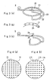
- Fig. 4(a) 71 shows the surface of the shower nozzle. On this shower nozzle which has a number of jet orifices 72, the same feedstock gas is jetted.
- two types of gas jet orifices 173 and 174 are formed. From one type 173 of these orifices, a feedstock gas containing nitrogen atom is jetted, while another feedstock gas containing tungsten atom is jetted from the remainders 174. In this case, these gases are mixed together and react with each other before attaining the surface of the object on which a film is to be formed, which supposedly results in the low film formation (deposition)rate achieved by the prior art.
- a nozzle shaped into a ring is further provided in the second gas inlet equipment.
- This nozzle has a number of gas jet orifices from which a gas is jetted toward the center of the ring, optionally somewhat shifting toward the object on which a film is to be formed.
- the feedstock gas supplied from the second gas inlet equipment can uniformly attain the surface of the object on which a film is to be formed.
- the feedstock gas supplied from the first gas inlet equipment attains the surface of the object on which a film is to be formed via the center of the ring of the nozzle. Therefore, the gases supplied respectively from the first and second gas inlet equipment can attain the surface of the object on which a film is to be formed, without being mixed together and thus the reaction can efficiently proceed on the surface of the object on which a film is to be formed.
- WF 6 ⁇ 4NH 3 is formed at a temperature less than 150°C while a W x N (i.e., a tungsten nitride film) is formed at a temperature exceeding 300°C.
- the adhesion preventive container is maintained at a temperature preferably of from 150 to 250°C (preferably around 200°C). As a result, neither WF 6 ⁇ 4NH 3 nor W x N is formed on the surface of the adhesion preventive container, thereby causing no dusting.
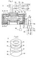
- sign 2 shows an example of the film forming apparatus used in the method according to the present invention which has a reactor 11.
- a cavity adhesion preventive container 8 is placed in this reactor 11.
- this adhesion preventive container 8 is provided with a bottom plate 31, a rectifier plate 32 and a top plate 33, each in a circular shape, and a cylindrical wall plate 30.
- Circular holes 36 to 38 are formed at the center of the bottom plate 31, the rectifier plate 32 and the top plate 33 respectively.
- the bottom plate 30 is located at the bottom of the wall plate 30, while the rectifier plate 32 is located above the bottom plate 31 and surrounded by the wall plate 30.
- the top plate 33 is located at the opening of the wall plate 30 above the rectifier plate 32.
- the bottom plate 31, the rectifier plate 32 and the top plate 33 are arranged in parallel at definite intervals and each fixed to the wall plate 30.
- the holes 36 to 38 formed respectively on the bottom plate 31, the rectifier plate 32 and the top plate 33 are each arranged in such a manner that the center thereof is located on the center axis of the wall plate 30.
- the adhesion preventive container 8 having the above-described constitution is placed as such on the bottom of the reactor 11.
- the reactor 11 is provided with a holder 14 on the bottom thereof and the adhesion preventive container 8 is placed so that the holder 14 is located in the hole 36 of the bottom plate 31 and the hole 37 of the rectifier plate 32.
- the surface of the holder 14 is located between the rectifier plate 31 and the top plate 33.
- a first gas source 45 and a second gas source 46 are provided outside the reactor 11.
- 61 1 to 61 4 are mass flow controller, and 62 1 to 62 8 are valves.
- the first gas source 45 is connected to a shower nozzle 12 as a first gas inlet equipment.
- a first gas inlet system consists of this first gas source 45 and the shower nozzle 12 which is a first gas inlet equipment.
- the shower nozzle 12 has a cavity structure and a number of orifices are formed on the bottom 18 thereof. Thus, a gas is supplied from the first gas source 45 into the cavity part of shower nozzle 12 is jetted from the orifices on the bottom.
- the shower nozzle 12 is located above the hole 38 of the top plate 33 and attached to the top part of the reactor 11 so that the bottom 18 of the shower nozzle 12 faces to the surface of the holder 14.
- the hole 38 of the top plate 33 is larger than the bottom 18 of the shower nozzle 12.
- the bottom 18 of the shower nozzle 12 is located almost at the same height as the top plate 33 but the bottom 18 is located lower than the hole 38 of the top plate 33.
- the gas jetted form the shower nozzle 12 is introduced directly into the adhesion preventive container 8 and blown to the surface of the holder 14.
- the second gas source 46 is connected to a gas jet member 4 as a second gas inlet equipment.
- a second gas inlet system 42 consists of the second gas source 46 and the gas jet member 4 which is a second gas inlet equipment.
- This gas jet member 4 which is roughly shaped into a ring, is arranged between the holder 14 and the shower nozzle 12 in the adhesion preventive container 8 in parallel to the surface of the holder 14. Namely, the gas jet member 4 is located between the rectifier plate 32 and the top plate 33 and in parallel to the rectifier plate 32 and the top plate 33.
- Fig. 3(a) is a perspective view of the gas jet member 4.
- This gas jet member 4 consists of a ring nozzle 21, a support 22 supporting this nozzle 21, and a pipe 23 with which the support 22 is connected to the gas inlet system 42 which is located outside of the reactor 11.
- the nozzle 21, the support 22 and the pipe 23 are each made up of a hollow pipe.
- a gas is introduced from the second gas source 46 into the gas jet member 4, the gas passes through the pipe 23 and the support 22 and attains the nozzle 21.
- the gas nozzle 21 shaped into a ring is provided a number of holes 25 on the inner face.
- Fig. 3(b) is an enlarged view of the holes 25.
- These holes 25 are arranged on somewhat lower part of the surface of the ring gas nozzle 21 at almost constant intervals so that the gas flown into the nozzle 21 is regularly discharged from these holes 25 somewhat downward toward the center.
- the first gas source 45 is provided with a gas cylinder containing the first feedstock gas comprising NH 3, while the second gas source 46 is provided with another gas cylinder containing the second feedstock gas comprising WF 6 , thus allowing the introduction of these gases respectively from the first and second gas inlet systems 41 and 42 into the reactor 11.
- the reactor 11 is evacuated into vacuum atmosphere with the evacuation system 48 connected to the reactor 11.
- the substrate holder 17 is comprised operable to lift up and down.
- the substrate 20 is carried into the reactor 11 while lifting up the substrate holder 17 and placed on the holder 14.
- This substrate 20 is arranged in parallel to the bottom 18 of the shower nozzle 12.
- the substrate holder 17 is taken down and the substrate 20 is adhered to the holder 14 followed by heating by switching on the heater 15.
- the adhesion preventive container 8 is heated with the inner heater as well as the heat radiated from the holder 14. In this step, the electricity supplied to the inner heater is controlled so as to maintain the temperature of the adhesion preventive container 8 to 200°C.
- the gas sources 45 and 46 are manipulated so that the first feedstock gas NH 3 is jetted from the shower nozzle 12 toward the substrate 20 and, at the same time, the second feedstock gas WF 6 is jetted from the nozzle 21 of the gas jet member 4.
- the first and second feedstock gases i.e., the NH 3 and WF 6 gases
- two different feedstock gases i.e., the NH 3 and WF 6 gases
- the pressure in the adhesion preventive container 8 can be maintained within the viscous flow region (i.e., 1.0 to 100 Pa) and the first feedstock gas and the second feedstock gas can separately attain the surface of the substrate 20 without being mixed together.
- the reaction of forming thin W x N proceeds on the surface of the substrate 20 and thus a thin W x N film is obtained.
- the substrate 20 is taken out from the reactor 11 and transported into a copper film forming apparatus. At the same time, another untreated substrate is carried into the reactor 11 and subjected to the formation of a thin W x N film.
- thin W x N films can be continuously formed.
- the adhesion preventive container 8 is filled up with the first feedstock NH 3 gas and the second WF 6 feedstock gas, which protects the inner wall of the reactor 11 from the deposition of WF 6 ⁇ 4NH 3 or W x N thereon.
- the adhesion preventive container 8 is filled up with the first feedstock NH 3 gas and the second WF 6 feedstock gas, which protects the inner wall of the reactor 11 from the deposition of WF 6 ⁇ 4NH 3 or W x N thereon.
- the temperature of the adhesion preventive container 8 is controlled within a range preferably of from 200 to 300°C, neither WF 6 ⁇ 4NH 3 , which is liable to be formed at lower temperatures, nor W x N, which is liable to be formed at higher temperatures, is formed.
- W x N can be formed in dust-free environment. Because of being removable, moreover, the adhesion preventive container 8 can be easily cleaned.
- a number of holes 25 are formed in the inner side of the gas jet member 4 in the above case, other constitutions may be employed therefor so long as the feedstock gas can uniformly jetted from two or more positions toward the substrate 20.
- a tip 24 of the support 22 is bent toward the central axis of the substrate located below and the feedstock gas is jetted from the hole 26 formed on the tip 24, as Fig. 3(c) shows.
- W x N is formed in vacuum (under reduced pressure) of 1.0 to 100 Pa in the above example, it can be formed under higher pressure, i.e., atmospheric pressure or more.
Landscapes
- Chemical & Material Sciences (AREA)
- General Chemical & Material Sciences (AREA)
- Chemical Kinetics & Catalysis (AREA)
- Engineering & Computer Science (AREA)
- Materials Engineering (AREA)
- Mechanical Engineering (AREA)
- Metallurgy (AREA)
- Organic Chemistry (AREA)
- Inorganic Chemistry (AREA)
- Chemical Vapour Deposition (AREA)
- Electrodes Of Semiconductors (AREA)
Description
- This invention relates to the technical field of forming metal nitrides. More particularly, it provides a technique adequate for forming tungsten nitride films.
- In recent years, aluminum has been replaced by copper as the material mainly employed in metal interconnecting films for semiconductor devices. In the case of aluminum films, titanium nitride films are formed as barrier films at the interface between the aluminum films and silicon substrates. However, these titanium nitride films are poor in the ability to prevent the diffusion of copper. Thus, WxN films (tungsten nitride films) have attracted attention as barrier films against copper films.
- Patent Abstracts of Japan, vol. 16, no. 55 describes the manufacture of a semi-conductor device wherein a tungsten nitride film is formed on a coated silicon substrate. It is essential that two gases such as nitrogen and oxygen are introduced from the first gas feed pipe while tungsten hexafluoride is introduced from the second gas feed pipe.
- In Patent Abstracts of Japan, vol. 1997, no. 4 a vacuum treating device is shown with which a thin film deposition can be made. The aim is to avoid the release of a thin film deposited on the inner surface of a vacuum vessel.
- It has been a practice to produce WxN films at a high temperature (i.e., 500°C or above) under high pressure (i.e., film-forming pressure: several thousand Pa). However, a large-scaled apparatus should be employed to sustain such a high pressure and, moreover, troublesome operations are needed for the maintenance thereof. In a pretreatment apparatus for forming WxN films and a film forming apparatus for forming copper film on the WxN films, substrates should be treated in vacuum. Thus, there arises an additional problem that these apparatuses are poor in the connection properties with a WxN film forming apparatus and thus the substrates cannot be treated continuously.
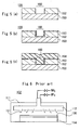
- Accordingly, it has been required to develop a film forming apparatus by which WxN films can be produced in vacuum (under reduced pressure). In Fig. 5(a), a
substrate 120, on which a WxN film and a copper film are to be formed, consists of asilicon substrate 150, asilicon oxide film 152 formed on thesilicon substrate 150 and apore 160 formed in thesilicon oxide film 152. - When a WxN film is to be formed on the
substrate 120 by using aCVD apparatus 102 of the prior art as shown in Fig. 6, areactor 111 is first evacuated. Then thesubstrate 120 is carried thereinto and placed on aholder 114 provided in the bottom side of thereactor 111. - A
shower nozzle 112 is provided in the ceiling side of thereactor 111. After heating thesubstrate 120 to a prescribed temperature with a heater contained in theholder 114, two types of feedstock gases (for example, WF6 gas and NH3 gas) are jetted from theshower nozzle 112 toward thesubstrate 120 as shown byarrows 151, thereby inducing the following chemical reaction:
4WF6 + 8NH3 → 2W2N + 24HF + 3N2.
Thus, a WxN film 153 is formed on the surface of thesubstrate 120 as shown in Fig. 5(b), wherein X is referred tentatively as to 2. - When a prescribed thickness of the WxN film is achieved, the
substrate 120 is taken out from thereactor 111. Then acopper film 154 is formed on the WxNfilm 153 as shown in Fig. 5 (c) and followed by the transportation to the subsequent stage, i.e., the patterning of thecopper film 154, etc. - When the WxN
film 153 and thecopper film 154 are formed in vacuum as described above, thesubstrate 120 can be continuously treated without exposing to the atmosphere by connecting a apparatus for forming a tungsten film and a apparatus for forming a copper film to a multi-chamber type apparatus. - However, a CVD apparatus of the prior art as described above suffers from the problem of serious dusting. This is because the reaction between WF6 and NH3 proceeds even at room temperature and not WxN but WF6·4NH3 etc. are formed at room temperature, different from the above reaction formula, and adhere to the inner wall of the
reactor 111. - When the wall of the
reactor 111 is heated to a temperature close to the temperature of thesubstrate 120, at least the formation of WF6·4NH3 can be prevented. In this case, however, WxN is deposited on the inner wall of thereactor 111 on the contrary and causes dusting. - In addition, the above-described
reactor 111 of the prior art suffers from another problem of a low growth speed of the WxN film. Thus, it has been required to clarify the cause of this phenomenon and to establish a countermeasure effective therefor. - The present invention, which has been made to overcome the above-described problems encountering in the prior art, aims at providing a technique for forming a tungsten nitride film without causing dusting, and a technique for forming a tungsten nitride film showing a high growth speed.
- To achieve these objects, the present invention relates to a method for producing a tungsten nitride film using a film forming apparatus provided with an evacuatable reactor, an adhesion preventive container placed in said reactor, a holder whereby a object on which the film is to be formed is located in said adhesion preventive container, a first gas inlet equipment which faces to said holder and constructed so that it can jet a gas into said adhesion preventive container, and a second gas inlet equipment which is constructed so that it can jet a gas between said first gas inlet equipment and said holder.
- The film forming apparatus is constructed so that, in said adhesion preventive container, at least the part around said material on which the film is to be formed is maintained at a temperature of 150 to 300°C.
- The film forming apparatus comprising said first gas inlet equipment has a shower nozzle provided with a number of gas jet orifices formed on the almost same plane.
- The film forming apparatus comprising said second gas inlet equipment has a nozzle made of a hollow pipe shaped into a ring and a number of gas jet orifices are formed in said hollow pipe.
- The present invention relates to a method for producing a tungsten nitride film which comprises jetting a first NH3 feedstock gas and a second WF6 feedstock gas into a reactor and reacting said first feedstock gas with said second feedstock gas so as to form a tungsten nitride film on the surface of a material on which the film is to be formed, wherein the distance between the position from which said first feedstock gas is jetted and the surface of said material on which the film is to be formed is different from the distance between the position from which said second feedstock gas is jetted and the surface of said material on which the film is to be formed.
- The present invention relates to the method for producing a tungsten nitride film which comprises providing an adhesion preventive container in said reactor and placing said object on which a film is to be formed in the adhesion preventive container; heating, in said adhesion preventive container, at least the part around said material on which the film is to be formed to a temperature of preferably 150 to 250°C; and jetting said first feedstock gas and second feedstock gas into said adhesion preventive container.
- The present invention relates to the method for producing a tungsten nitride film, wherein one of said first feedstock gas and second feedstock gas is jetted downward in the vertical direction toward the surface of said object on which a film is to be formed.
- The present invention relates to the method for producing a tungsten nitride film, wherein, between said first feedstock gas and second feedstock gas, the one gas jetted from the lower position is jetted sideways toward center of said object on which a film is to be formed.
- Many other features, advantages and additional objects of the present invention will become manifest to those versed in the art upon making reference to the detailed description which follows and the accompanying sheet of drawings.
-
- Fig. 1 is a drawing which shows an example of the film forming apparatus used in the method according to the present invention.
- Fig. 2 is a drawing which illustrates the adhesion preventive container of the film forming apparatus.
- Fig. 3(a) is a perspective view of the nozzle shaped into a ring; Fig. 3(b) is an enlarged partial view thereof; and Fig. 3(c) is a perspective view of a nozzle in another shape.
- Fig. 4 (a) is a plan view of an example of the shower nozzle of the present invention; and Fig. 4 (b) is a plan view of a shower nozzle of the prior art.
- Fig. 5 (a) - (c) are drawings which show the steps of forming a tungsten nitride film and a copper film.
- Fig. 6 is a drawing which shows a apparatus for forming a tungsten nitride film of the prior art.
- The film forming apparatus used in the method according to the present invention, which has the constitution as described above, has an adhesion preventive container placed in the reactor. In this adhesion preventive container, a holder is provided so that a object on which a film is to be formed (i.e., the substrate) can be hold in the adhesion preventive container.
- This film forming apparatus is provided with a first gas inlet equipment and a second gas inlet equipment through which feedstock gases are respectively jetted into the adhesion preventive container. The second gas inlet equipment is located at such a position that it can jet the gas between the jetting position of the first gas inlet equipment and the holder.
- By locating the gas jetting positions of the first and second gas inlet equipment at different heights on the surface of the object on which a film is to be formed and jetting the feedstock gases into the adhesion preventive container, the first and second feedstock gases respectively jetted from the gas inlet equipment can attain the surface of the object on which a film is to be formed located on the holder without mixing with each other even under a pressure within the viscous flow region (i.e., 1.0 to 100 Pa).
- When the first feedstock gas being NH3 gas and the second feedstock gas being WF6 gas are supplied respectively from the first gas inlet equipment and the second gas inlet equipment, therefore, these gases react with each other not in the space but on the surface of the object on which a film is to be formed and thus a tungsten nitride film can be efficiently formed.
- A tungsten nitride film having a good film thickness distribution can be formed on the surface of the object on which a film is to be formed by providing the first gas inlet equipment with a shower nozzle and thus jetting downward the feedstock gas toward the object on which a film is to be formed. Fig. 4(a) 71 shows the surface of the shower nozzle. On this shower nozzle which has a number of
jet orifices 72, the same feedstock gas is jetted. - In the
shower nozzle 171 of the prior art shown in Fig. 4 (b), two types ofgas jet orifices type 173 of these orifices, a feedstock gas containing nitrogen atom is jetted, while another feedstock gas containing tungsten atom is jetted from theremainders 174. In this case, these gases are mixed together and react with each other before attaining the surface of the object on which a film is to be formed, which supposedly results in the low film formation (deposition)rate achieved by the prior art. - In the present invention, a nozzle shaped into a ring is further provided in the second gas inlet equipment. This nozzle has a number of gas jet orifices from which a gas is jetted toward the center of the ring, optionally somewhat shifting toward the object on which a film is to be formed. Thus, the feedstock gas supplied from the second gas inlet equipment can uniformly attain the surface of the object on which a film is to be formed.
- In this case, the feedstock gas supplied from the first gas inlet equipment attains the surface of the object on which a film is to be formed via the center of the ring of the nozzle. Therefore, the gases supplied respectively from the first and second gas inlet equipment can attain the surface of the object on which a film is to be formed, without being mixed together and thus the reaction can efficiently proceed on the surface of the object on which a film is to be formed.
- When a feedstock gas containing NH3 gas and another feedstock gas containing WF6 gas are separately introduced into the adhesion preventive container in particular under a pressure of from 1.0 to 100 Pa, WF6·4NH3 is formed at a temperature less than 150°C while a WxN (i.e., a tungsten nitride film) is formed at a temperature exceeding 300°C.
- In the present invention, the adhesion preventive container is maintained at a temperature preferably of from 150 to 250°C (preferably around 200°C). As a result, neither WF6·4NH3 nor WxN is formed on the surface of the adhesion preventive container, thereby causing no dusting.
- These and other objects of the invention will become more apparent in the detailed description and examples which follow.
- Now, the present invention will be described by reference to the attached drawings.
- In Fig. 1, sign 2 shows an example of the film forming apparatus used in the method according to the present invention which has a
reactor 11. A cavity adhesionpreventive container 8 is placed in thisreactor 11. - As Fig. 2 shows, this adhesion
preventive container 8 is provided with abottom plate 31, arectifier plate 32 and atop plate 33, each in a circular shape, and acylindrical wall plate 30. - Circular holes 36 to 38 are formed at the center of the
bottom plate 31, therectifier plate 32 and thetop plate 33 respectively. - The
bottom plate 30 is located at the bottom of thewall plate 30, while therectifier plate 32 is located above thebottom plate 31 and surrounded by thewall plate 30. Thetop plate 33 is located at the opening of thewall plate 30 above therectifier plate 32. - The
bottom plate 31, therectifier plate 32 and thetop plate 33 are arranged in parallel at definite intervals and each fixed to thewall plate 30. - The
holes 36 to 38 formed respectively on thebottom plate 31, therectifier plate 32 and thetop plate 33 are each arranged in such a manner that the center thereof is located on the center axis of thewall plate 30. - The adhesion
preventive container 8 having the above-described constitution is placed as such on the bottom of thereactor 11. - The
reactor 11 is provided with a holder 14 on the bottom thereof and the adhesionpreventive container 8 is placed so that the holder 14 is located in thehole 36 of thebottom plate 31 and thehole 37 of therectifier plate 32. The surface of the holder 14 is located between therectifier plate 31 and thetop plate 33. - A
first gas source 45 and asecond gas source 46, each consisting of a gas cylinder, a mass flow controller, valves, pipes, etc., are provided outside thereactor 11. - In Fig.1, 611 to 614 are mass flow controller, and 621 to 628 are valves.
- The
first gas source 45 is connected to a shower nozzle 12 as a first gas inlet equipment. A first gas inlet system consists of thisfirst gas source 45 and the shower nozzle 12 which is a first gas inlet equipment. - The shower nozzle 12 has a cavity structure and a number of orifices are formed on the bottom 18 thereof. Thus, a gas is supplied from the
first gas source 45 into the cavity part of shower nozzle 12 is jetted from the orifices on the bottom. - The shower nozzle 12 is located above the
hole 38 of thetop plate 33 and attached to the top part of thereactor 11 so that the bottom 18 of the shower nozzle 12 faces to the surface of the holder 14. - The
hole 38 of thetop plate 33 is larger than the bottom 18 of the shower nozzle 12. The bottom 18 of the shower nozzle 12 is located almost at the same height as thetop plate 33 but the bottom 18 is located lower than thehole 38 of thetop plate 33. - Due to this construction, the gas jetted form the shower nozzle 12 is introduced directly into the adhesion
preventive container 8 and blown to the surface of the holder 14. - The
second gas source 46 is connected to agas jet member 4 as a second gas inlet equipment. A secondgas inlet system 42 consists of thesecond gas source 46 and thegas jet member 4 which is a second gas inlet equipment. - This
gas jet member 4, which is roughly shaped into a ring, is arranged between the holder 14 and the shower nozzle 12 in the adhesionpreventive container 8 in parallel to the surface of the holder 14. Namely, thegas jet member 4 is located between therectifier plate 32 and thetop plate 33 and in parallel to therectifier plate 32 and thetop plate 33. - Fig. 3(a) is a perspective view of the
gas jet member 4. - This
gas jet member 4 consists of aring nozzle 21, asupport 22 supporting thisnozzle 21, and apipe 23 with which thesupport 22 is connected to thegas inlet system 42 which is located outside of thereactor 11. - The
nozzle 21, thesupport 22 and thepipe 23 are each made up of a hollow pipe. When a gas is introduced from thesecond gas source 46 into thegas jet member 4, the gas passes through thepipe 23 and thesupport 22 and attains thenozzle 21. - The
gas nozzle 21 shaped into a ring is provided a number ofholes 25 on the inner face. Fig. 3(b) is an enlarged view of theholes 25. Theseholes 25 are arranged on somewhat lower part of the surface of thering gas nozzle 21 at almost constant intervals so that the gas flown into thenozzle 21 is regularly discharged from theseholes 25 somewhat downward toward the center. - Next, a method for forming a tungsten nitride film by using the above-described film forming apparatus 2 will be illustrated.
- In this case, the
first gas source 45 is provided with a gas cylinder containing the first feedstock gas comprising NH3, while thesecond gas source 46 is provided with another gas cylinder containing the second feedstock gas comprising WF6, thus allowing the introduction of these gases respectively from the first and secondgas inlet systems reactor 11. - First, the
reactor 11 is evacuated into vacuum atmosphere with theevacuation system 48 connected to thereactor 11. Thesubstrate holder 17 is comprised operable to lift up and down. Then thesubstrate 20 is carried into thereactor 11 while lifting up thesubstrate holder 17 and placed on the holder 14. Thissubstrate 20 is arranged in parallel to the bottom 18 of the shower nozzle 12. Next, thesubstrate holder 17 is taken down and thesubstrate 20 is adhered to the holder 14 followed by heating by switching on the heater 15. - When another inner heater provided within the adhesion
preventive container 8 is also switched on, the adhesionpreventive container 8 is heated with the inner heater as well as the heat radiated from the holder 14. In this step, the electricity supplied to the inner heater is controlled so as to maintain the temperature of the adhesionpreventive container 8 to 200°C. - When temperature of the
substrate 20 is elevated and attains to 300°C or higher, thegas sources substrate 20 and, at the same time, the second feedstock gas WF6 is jetted from thenozzle 21 of thegas jet member 4. Thus, the first and second feedstock gases (i.e., the NH3 and WF6 gases) are blown onto thesubstrate 20. - In this case, two different feedstock gases (i.e., the NH3 and WF6 gases) are separately jetted respectively from the shower nozzle 12 and the
gas jet member 4, as described above. By controlling the supply rates of the gases by manipulating thefirst gas source 41 andsecond gas source 42, the pressure in the adhesionpreventive container 8 can be maintained within the viscous flow region (i.e., 1.0 to 100 Pa) and the first feedstock gas and the second feedstock gas can separately attain the surface of thesubstrate 20 without being mixed together. As a result, the reaction of forming thin WxN proceeds on the surface of thesubstrate 20 and thus a thin WxN film is obtained. - When the thin WxN film having a prescribed film thickness is formed, the
substrate 20 is taken out from thereactor 11 and transported into a copper film forming apparatus. At the same time, another untreated substrate is carried into thereactor 11 and subjected to the formation of a thin WxN film. Thus, thin WxN films can be continuously formed. - In the above-described film forming apparatus 2, the adhesion
preventive container 8 is filled up with the first feedstock NH3 gas and the second WF6 feedstock gas, which protects the inner wall of thereactor 11 from the deposition of WF6·4NH3 or WxN thereon. Thus, no dust evolves from thereactor 11 and a defect-free WxN film can be produced. - Since the temperature of the adhesion
preventive container 8 is controlled within a range preferably of from 200 to 300°C, neither WF6·4NH3, which is liable to be formed at lower temperatures, nor WxN, which is liable to be formed at higher temperatures, is formed. Thus, WxN can be formed in dust-free environment. Because of being removable, moreover, the adhesionpreventive container 8 can be easily cleaned. - As described above, by using the thin film forming apparatus 2 in the method according to the present invention, different feedstock gases are not mixed together but can separately attain a substrate and the reaction efficiently proceeds on the substrate surface. Thus, a WxN thin film made of the reaction product can grow quickly without causing dusting and a WxN film with excellent qualities can be formed.
- Although a number of
holes 25 are formed in the inner side of thegas jet member 4 in the above case, other constitutions may be employed therefor so long as the feedstock gas can uniformly jetted from two or more positions toward thesubstrate 20. For example, it is also possible that atip 24 of thesupport 22 is bent toward the central axis of the substrate located below and the feedstock gas is jetted from thehole 26 formed on thetip 24, as Fig. 3(c) shows. - Although WxN is formed in vacuum (under reduced pressure) of 1.0 to 100 Pa in the above example, it can be formed under higher pressure, i.e., atmospheric pressure or more.
- By using the present invention, different feedstock gases are not mixed together but can separately attain the surface of a object on which a film is to be formed. Thus, the film-formation speed can be elevated and a uniform film thickness can be obtained.
- Also, no reaction occurs on the surface of the adhesion preventive container and thus no dusting arises. In addition, the feedstock gases are not consumed on the surface of the adhesion preventive container. Therefore, the reaction can efficiently proceed on the surface of the object on which a film is to be formed and no dust adheres to the surface of the adhesion preventive container.
Claims (3)
- A method for producing a tungsten nitride film which comprises jetting an NH3 gas and a WF6 gas into a reactor and reacting said NH3 gas with said WF6 gas so as to form a tungsten nitride film on the surface of a material on which the film is to be formed;
wherein the distance between the position from which said NH3 gas is jetted and the surface of said material on which the film is to be formed is different from the distance between the position from which said WF6 gas is jetted and the surface of said material on which the film is to be formed;
an adhesion preventive container is provided in said reactor where said object on which a film is to be formed is placed;
at least the part around said material on which the film is to be formed is heated to a temperature of 150 to 300°C in said adhesion preventive container; and
said NH3 gas and WF6 gas are jetted into said adhesion preventive container. - The method for producing a tungsten nitride film as claimed in claim 1, wherein one of said NH3 gas and WF6 gas is jetted downward in the vertical direction toward the surface of said object on which a film is to be formed.
- The method for producing a tungsten nitride film as claimed in claim 1, wherein, between said NH3 gas and WF6 gas, the one gas jetted from the lower position is jetted sideways toward center of said object on which a film is to be formed.
Applications Claiming Priority (2)
| Application Number | Priority Date | Filing Date | Title |
|---|---|---|---|
| JP11013791A JP2000212749A (en) | 1999-01-22 | 1999-01-22 | Thin film forming apparatus and tungsten nitride thin film manufacturing method |
| JP1379199 | 1999-01-22 |
Publications (2)
| Publication Number | Publication Date |
|---|---|
| EP1024210A1 EP1024210A1 (en) | 2000-08-02 |
| EP1024210B1 true EP1024210B1 (en) | 2006-05-17 |
Family
ID=11843083
Family Applications (1)
| Application Number | Title | Priority Date | Filing Date |
|---|---|---|---|
| EP00100937A Expired - Lifetime EP1024210B1 (en) | 1999-01-22 | 2000-01-18 | Apparatus and method for producing tungsten nitride film |
Country Status (6)
| Country | Link |
|---|---|
| US (2) | US6312761B1 (en) |
| EP (1) | EP1024210B1 (en) |
| JP (1) | JP2000212749A (en) |
| KR (1) | KR100630647B1 (en) |
| DE (1) | DE60027935T2 (en) |
| TW (1) | TW579393B (en) |
Cited By (3)
| Publication number | Priority date | Publication date | Assignee | Title |
|---|---|---|---|---|
| US7655543B2 (en) | 2007-12-21 | 2010-02-02 | Asm America, Inc. | Separate injection of reactive species in selective formation of films |
| US7939447B2 (en) | 2007-10-26 | 2011-05-10 | Asm America, Inc. | Inhibitors for selective deposition of silicon containing films |
| US8486191B2 (en) | 2009-04-07 | 2013-07-16 | Asm America, Inc. | Substrate reactor with adjustable injectors for mixing gases within reaction chamber |
Families Citing this family (11)
| Publication number | Priority date | Publication date | Assignee | Title |
|---|---|---|---|---|
| US6635570B1 (en) * | 1999-09-30 | 2003-10-21 | Carl J. Galewski | PECVD and CVD processes for WNx deposition |
| JP2002085950A (en) * | 2000-09-18 | 2002-03-26 | Horiba Ltd | Fluid mixing device |
| KR101035221B1 (en) | 2002-12-27 | 2011-05-18 | 가부시키가이샤 알박 | Method of forming tungsten nitride film |
| KR101178743B1 (en) | 2004-04-12 | 2012-09-07 | 가부시키가이샤 알박 | Method for forming barrier film, and method for forming electrode film |
| US7420227B2 (en) * | 2005-06-22 | 2008-09-02 | National Chiao Tung University | Cu-metalized compound semiconductor device |
| US8148564B2 (en) * | 2006-08-30 | 2012-04-03 | Wayne State University | Compounds for forming metal nitrides |
| JP4523661B1 (en) * | 2009-03-10 | 2010-08-11 | 三井造船株式会社 | Atomic layer deposition apparatus and thin film forming method |
| US9499905B2 (en) * | 2011-07-22 | 2016-11-22 | Applied Materials, Inc. | Methods and apparatus for the deposition of materials on a substrate |
| WO2014097280A1 (en) * | 2012-12-21 | 2014-06-26 | Prasad Narhar Gadgil | Methods of low temperature deposition of ceramic thin films |
| WO2017165016A1 (en) * | 2016-03-25 | 2017-09-28 | Applied Materials, Inc. | Chamber liner for high temperature processing |
| CN114850003B (en) * | 2021-02-03 | 2023-06-27 | 芝浦机械电子装置株式会社 | Heating treatment device |
Family Cites Families (10)
| Publication number | Priority date | Publication date | Assignee | Title |
|---|---|---|---|---|
| JPS59131511A (en) * | 1983-01-17 | 1984-07-28 | Zenko Hirose | Formation of film of amorphous silicon |
| JPS62116770A (en) * | 1985-11-15 | 1987-05-28 | Canon Inc | Film forming equipment |
| JP2859632B2 (en) * | 1988-04-14 | 1999-02-17 | キヤノン株式会社 | Film forming apparatus and film forming method |
| JP2803297B2 (en) * | 1990-03-05 | 1998-09-24 | 日本電気株式会社 | Method for manufacturing semiconductor device |
| KR930001300A (en) * | 1991-06-10 | 1993-01-16 | 김광호 | Chemical vapor deposition method and apparatus therefor |
| US5470800A (en) * | 1992-04-03 | 1995-11-28 | Sony Corporation | Method for forming an interlayer film |
| US5534072A (en) * | 1992-06-24 | 1996-07-09 | Anelva Corporation | Integrated module multi-chamber CVD processing system and its method for processing subtrates |
| JP3590416B2 (en) * | 1993-11-29 | 2004-11-17 | アネルバ株式会社 | Thin film forming method and thin film forming apparatus |
| JP3360098B2 (en) * | 1995-04-20 | 2002-12-24 | 東京エレクトロン株式会社 | Shower head structure of processing equipment |
| JP3699504B2 (en) * | 1995-05-30 | 2005-09-28 | アネルバ株式会社 | Vacuum processing equipment |
-
1999
- 1999-01-22 JP JP11013791A patent/JP2000212749A/en active Pending
- 1999-12-27 KR KR1019990062682A patent/KR100630647B1/en not_active Expired - Fee Related
- 1999-12-30 TW TW088123340A patent/TW579393B/en not_active IP Right Cessation
-
2000
- 2000-01-18 EP EP00100937A patent/EP1024210B1/en not_active Expired - Lifetime
- 2000-01-18 DE DE60027935T patent/DE60027935T2/en not_active Expired - Lifetime
- 2000-01-21 US US09/489,338 patent/US6312761B1/en not_active Expired - Lifetime
-
2001
- 2001-07-26 US US09/912,504 patent/US20020000199A1/en not_active Abandoned
Cited By (4)
| Publication number | Priority date | Publication date | Assignee | Title |
|---|---|---|---|---|
| US7939447B2 (en) | 2007-10-26 | 2011-05-10 | Asm America, Inc. | Inhibitors for selective deposition of silicon containing films |
| US7655543B2 (en) | 2007-12-21 | 2010-02-02 | Asm America, Inc. | Separate injection of reactive species in selective formation of films |
| US7897491B2 (en) | 2007-12-21 | 2011-03-01 | Asm America, Inc. | Separate injection of reactive species in selective formation of films |
| US8486191B2 (en) | 2009-04-07 | 2013-07-16 | Asm America, Inc. | Substrate reactor with adjustable injectors for mixing gases within reaction chamber |
Also Published As
| Publication number | Publication date |
|---|---|
| US6312761B1 (en) | 2001-11-06 |
| KR20000052580A (en) | 2000-08-25 |
| KR100630647B1 (en) | 2006-10-02 |
| TW579393B (en) | 2004-03-11 |
| JP2000212749A (en) | 2000-08-02 |
| DE60027935T2 (en) | 2007-04-26 |
| DE60027935D1 (en) | 2006-06-22 |
| US20020000199A1 (en) | 2002-01-03 |
| EP1024210A1 (en) | 2000-08-02 |
Similar Documents
| Publication | Publication Date | Title |
|---|---|---|
| EP1024210B1 (en) | Apparatus and method for producing tungsten nitride film | |
| CN100519834C (en) | Device and method for manufacturing thin films | |
| US5580822A (en) | Chemical vapor deposition method | |
| US6306216B1 (en) | Apparatus for deposition of thin films on wafers through atomic layer epitaxial process | |
| US11286566B2 (en) | Apparatus for deposition of a III-V semiconductor layer | |
| KR101044355B1 (en) | Gas Head and Thin Film Manufacturing Equipment | |
| JP4399206B2 (en) | Thin film manufacturing equipment | |
| US20050034662A1 (en) | Methods, systems, and apparatus for uniform chemical-vapor depositions | |
| US8450220B2 (en) | Substrate processing apparatus , method of manufacturing semiconductor device, and method of manufacturing substrate | |
| US6004885A (en) | Thin film formation on semiconductor wafer | |
| TWI423383B (en) | Substrate support for the III-V film growth reaction chamber, its reaction chamber and process treatment | |
| JPH09246192A (en) | Thin film gas phase growing device | |
| KR20020027211A (en) | Chemical vapor deposition apparatus and chemical vapor deposition method | |
| US20130220222A1 (en) | Gas Distribution Apparatus with Heat Exchanging Channels | |
| WO2012120991A1 (en) | Substrate processing apparatus and method for manufacturing substrate | |
| KR100580062B1 (en) | Chemical vapor deposition apparatus and film deposition method | |
| JP2005054252A (en) | Thin film production apparatus and production method | |
| KR100369859B1 (en) | Apparatus for Atomic Layer Deposition | |
| JP5011631B2 (en) | Semiconductor manufacturing apparatus and semiconductor manufacturing system | |
| JP3816090B2 (en) | Chemical vapor deposition apparatus and film growth method | |
| JPH08104984A (en) | Gas introducing apparatus and method and method for forming tungsten thin film | |
| JP2026051608A (en) | Substrate processing apparatus and substrate processing method | |
| JPH04337627A (en) | Vapor growth device | |
| JPH03190218A (en) | semiconductor manufacturing equipment | |
| JPS60253213A (en) | Vapor growth device and vapor growth method according to device thereof |
Legal Events
| Date | Code | Title | Description |
|---|---|---|---|
| PUAI | Public reference made under article 153(3) epc to a published international application that has entered the european phase |
Free format text: ORIGINAL CODE: 0009012 |
|
| AK | Designated contracting states |
Kind code of ref document: A1 Designated state(s): DE FR GB NL |
|
| AX | Request for extension of the european patent |
Free format text: AL;LT;LV;MK;RO;SI |
|
| 17P | Request for examination filed |
Effective date: 20000713 |
|
| AKX | Designation fees paid |
Free format text: DE FR GB NL |
|
| 17Q | First examination report despatched |
Effective date: 20020719 |
|
| GRAP | Despatch of communication of intention to grant a patent |
Free format text: ORIGINAL CODE: EPIDOSNIGR1 |
|
| GRAS | Grant fee paid |
Free format text: ORIGINAL CODE: EPIDOSNIGR3 |
|
| GRAA | (expected) grant |
Free format text: ORIGINAL CODE: 0009210 |
|
| AK | Designated contracting states |
Kind code of ref document: B1 Designated state(s): DE FR GB NL |
|
| REG | Reference to a national code |
Ref country code: GB Ref legal event code: FG4D |
|
| REF | Corresponds to: |
Ref document number: 60027935 Country of ref document: DE Date of ref document: 20060622 Kind code of ref document: P |
|
| ET | Fr: translation filed | ||
| PLBE | No opposition filed within time limit |
Free format text: ORIGINAL CODE: 0009261 |
|
| STAA | Information on the status of an ep patent application or granted ep patent |
Free format text: STATUS: NO OPPOSITION FILED WITHIN TIME LIMIT |
|
| 26N | No opposition filed |
Effective date: 20070220 |
|
| REG | Reference to a national code |
Ref country code: FR Ref legal event code: PLFP Year of fee payment: 17 |
|
| REG | Reference to a national code |
Ref country code: FR Ref legal event code: PLFP Year of fee payment: 18 |
|
| REG | Reference to a national code |
Ref country code: FR Ref legal event code: PLFP Year of fee payment: 19 |
|
| PGFP | Annual fee paid to national office [announced via postgrant information from national office to epo] |
Ref country code: GB Payment date: 20190124 Year of fee payment: 20 Ref country code: NL Payment date: 20190122 Year of fee payment: 20 Ref country code: FR Payment date: 20190122 Year of fee payment: 20 Ref country code: DE Payment date: 20190129 Year of fee payment: 20 |
|
| REG | Reference to a national code |
Ref country code: DE Ref legal event code: R071 Ref document number: 60027935 Country of ref document: DE |
|
| REG | Reference to a national code |
Ref country code: NL Ref legal event code: MK Effective date: 20200117 |
|
| REG | Reference to a national code |
Ref country code: GB Ref legal event code: PE20 Expiry date: 20200117 |
|
| PG25 | Lapsed in a contracting state [announced via postgrant information from national office to epo] |
Ref country code: GB Free format text: LAPSE BECAUSE OF EXPIRATION OF PROTECTION Effective date: 20200117 |