EP1021640B1 - Arched support structure - Google Patents
Arched support structure Download PDFInfo
- Publication number
- EP1021640B1 EP1021640B1 EP98946576A EP98946576A EP1021640B1 EP 1021640 B1 EP1021640 B1 EP 1021640B1 EP 98946576 A EP98946576 A EP 98946576A EP 98946576 A EP98946576 A EP 98946576A EP 1021640 B1 EP1021640 B1 EP 1021640B1
- Authority
- EP
- European Patent Office
- Prior art keywords
- sections
- arch
- support structure
- units
- excavation
- Prior art date
- Legal status (The legal status is an assumption and is not a legal conclusion. Google has not performed a legal analysis and makes no representation as to the accuracy of the status listed.)
- Expired - Lifetime
Links
Images


Classifications
-
- E—FIXED CONSTRUCTIONS
- E21—EARTH OR ROCK DRILLING; MINING
- E21D—SHAFTS; TUNNELS; GALLERIES; LARGE UNDERGROUND CHAMBERS
- E21D9/00—Tunnels or galleries, with or without linings; Methods or apparatus for making thereof; Layout of tunnels or galleries
- E21D9/005—Tunnels or galleries, with or without linings; Methods or apparatus for making thereof; Layout of tunnels or galleries by forcing prefabricated elements through the ground, e.g. by pushing lining from an access pit
Definitions
- This application relates to the construction of underground structures in tunnel excavations without causing surface disruption.
- This type of excavation technique has been developed in the last 30 years and there is a growing need to install structures such as, for example, traffic underpasses, below an existing rail track or highway without stopping the use and operation of the same.
- Another example is the creation of a metro station below a busy street or property.
- a known approach is to prepare the structure to be installed at the side of the excavation and then jack it horizontally into position in the excavation. This has the disadvantage of requiring large constructions to be formed at the side and an extended area to be prepared for carrying out the work, usually of at least the same dimensions as the installation. It is also a process that is time consuming as a great deal of preparatory work has to be done in forming the working areas and casting the structure units.
- a second known approach is a modular approach where a series of pre-cast units are jacked, one on top of another, to form piers and abutments. This is a system which has found extensive use but has the disadvantage of not providing a complete solution to the problem as, although the majority of the excavation work can be completed without disruption it is necessary at some stage to complete the work by taking possession of the excavation so as to allow installation of the spanning beams.
- a third known approach is to create a structure of arch shaped cross section which is formed by a series of relatively small section tubes which run along the length of the structure. This provides a canopy which allows excavation to take place safely underneath.
- the disadvantages with this is that it is difficult and expensive to place all the tubes in position and, normally it is necessary to provide props for the arch across the base of the same and put in temporary support beams to support the tube arch and these procedures are required to be undertaken as work progresses.
- the aim of the present invention is to provide an improved process of supporting material excavations by utilising a modular pre-cast unit based on the principle of using units formed of an arch shape such that a series of said units allow an arch structure to be formed, said arch being an efficient form of carrying live and dead loads and therefore well suited to creating an underground structure.
- the approach is to pre-cast arch panels, erect them in the excavated area and jack the assembled elements forward to form the structure.
- a support structure which can be used to support excavated areas during and/or following excavation, said support structure including a series of upstanding arch shaped sections, positioned along the length of the excavated area, one after the other, and characterised in that the ends of said arch sections are located along a series of supporting units, so that said arch sections can be pushed or jacked in an upstanding position into the excavated area.
- the units have recessed sections, which, when the units are laid end to end, form a track along which the arch sections can slide when jacked.
- two linear tracks are formed, said tracks spaced apart by a distance determined by the space between the ends of said arch sections.
- each of the arch sections are pre-cast. Yet further, each of the arch sections are formed from a series of panels, constructed on site and prior to insertion into the tunnel.
- a method for forming a support structure for an excavated area during and/or after excavation of the same comprising, as the tunnel is excavated, pushing or jacking a series of sections in an upstanding position one after another into said excavated area, characterised in that the sections are arch sections in order to form an arch shaped support structure.
- the excavated area is a tunnel and the method comprises the steps of jacking a series of arch sections at intervals to increase the length of the support structure into the tunnel as the tunnel is excavated.
- the activity of the tunnel excavation takes place to the front of the first of the arch sections introduced.
- supporting units are first positioned in the excavation to act as bases and guides along which the arch structures are introduced.
- the supporting units extend upwardly to form the side walls of the arch shaped structure and it is the curved arch sections which are introduced to form the arch shaped structure.
- the arch sections include both the roof and side walls when jacked into the excavation.
- the method of the invention has a number of technical and economic advantages.
- Arch sections can be formed from a number of panels by factory fabrication, delivered to site and connected together to form the arch.
- a temporary shield can be fitted at the leading face, i.e. in front of the first arch section, which allows excavation work to be undertaken safely. This shield is recovered at the end of the excavation and can be re-used for excavations thereafter.
- a shield can be provided at the front of each supporting unit to allow excavation to proceed safely.
- arch panels reduces the temporary working areas required at the excavation site and requires less heavy handling equipment, than with conventional techniques.
- the ends of the panel sections are located in tracks formed by a series of supporting units which are jacked into the tunnel and the method further includes the step of jacking said supporting units into the tunnel to provide tracks of a sufficient length to receive the arch sections to form the support structure and therefore may be advanced to a further position into the excavation than the arch sections.
- the units are required to be manipulated after jacking to expose recessed portions to allow the formation of the tracks.
- hydrophilic gaskets or groutable injection hoses can be introduced between panels as they are installed in the working pit which serve to waterproof the joints and it should be appreciated that there are many possible variations of details in the design of the foundations and the arch configuration and span.
- double, side by side arched structures can be created, for example, for a tunnel for the two carriageways of a divided highway.
- three or four sets of in line supporting units are provided, said supporting units comprising two lines of outer supporting units and a centre line of double units and/or single units having two guide tracks formed therein, thus allowing the introduction of two sets of side by side sections along said supporting units.
- tunnels typically of circular cross section, along the line of the support structure to be formed and said tunnels spaced apart by the spacing required for the arch sections.
- the tunnels are driven by jacking or by segment construction.
- a track for the reception of the ends of the arch sections which again pass along the length of the tracks as with the supporting units and therefore act in a similar manner to support the arch sections.
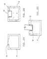
- a series of supporting or foundation units 4 are driven into the excavation material to form the base 6,6' and base reaction (horizontal and vertical load components) for the arch sections.
- These supporting units are designed to be of the correct dimensions for the loads and are installed by driving them into the tunnel excavation by pipe jacking methods.
- the units can be pre-cast off site in suitable handlable lengths and then brought to site as required.
- the units are designed so that after being installed they can be modified by undertaking work from inside the units by workers to provide a finished foundation structure for the structure and form tracks 10, 10', at the correct level as shown in Figures 2A-2C whereby the supporting units 4 are shown in Figure 2A in the form in which they are jacked.
- Figure 2B shows the supporting units after manipulation when positioned in the excavation and Figure 2C shows the track 10 with an end of an arch section 12 located therein.
- the units 4 have removable covers 14 which are removed progressively during the excavation of the soil from within the shield 16 to expose the guide tracks 10,10'.
- the units form a track guide and seating during installation of the arch sections and the permanent foundation, thereafter.
- the guide channels on the same are levelled so that the tracks formed on the same are level and the units are then pumped with concrete to form a solid foundation.
- the next stage in the method is to erect the temporary cutting shield 20 of Figure 3A which is fabricated in steel with the same outside dimensions, plus a small overcut, as the outside dimension of the arch sections.
- Some overcut in the excavation allows a reduction in soil friction and allows the introduction of measures to improve jacking of the sections such as lubrication or drag sheets
- the shield depending on the geotechnical conditions, can be fitted with shelves, compartments, doors, advance spiles and other devices used in tunnelling excavation as required. These devices assist in controlling the face stability and allow excavation machinery to be operated and excavation to proceed at the various levels of the tunnel.
- the shield is introduced into the soil through the head wall and along the tracks 10, 10'of the supporting units and excavation at the face commences, typically by face miners with the aid of mechanical equipment.
- arch sections 12 are jacked into the excavation behind the shield and along the tracks 10, 10' as shown in Figures 3A and 3B.
- a steel jacking ring 28 can be used to distribute the jacking loads uniformly onto the arch sections and in one embodiment shown in Figure 3A spacers 30 are used to allow the jacking reaction from the jacking rig 31 to be transferred onto the reaction wall 32.
- spacers 30 are used to allow the jacking reaction from the jacking rig 31 to be transferred onto the reaction wall 32.
- Individual arch sections can be of any suitable dimension, but typically 2 to 3 metres in length.
- the ends of the sections 12 are located at the end foots in the tracks 10, 10' of the supporting units 4 so they cannot spread apart during the jacking operation or thereafter.
- the staggering of the joints of the supporting units 4 is possible to allow use of the previously placed arch section to provide support for the next one.
- the supporting units extending outwith the excavated area into the working or reception area so as to allow the shield 20 and arch sections 12 to be provided in the correct configuration prior to jacking and, as they are then held in the tracks 10, 10' they can not deviate from line or level.
- the arch sections are introduced and hence pushed forward as excavation advances by jacks mounted in a suitable frame and having a reaction against a suitable structure. Such arrangements are well known and widely used. When the end of the excavation is reached and the reception shaft of the excavation is reached, the shield is removed.
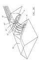
- Figure 3C illustrates a partially formed support structure 31 formed of a series of arch structures 12 and supporting units 4 with part of the arch sections 12', 12" removed in the drawing for ease of reference only.
- the support structure is being formed under a railway line embankment 33 as shown.
- FIG. 4 illustrates a cross section of one tunnel, said tunnel 40 typically of circular cross section, and provided along the line of the support structure to be formed.
- the tunnels are driven by jacking or by segment construction.
- a track 42 which can be exposed for the reception of the end 44 of the arch sections 12 which again pass along the length of the tracks as with the supporting units and therefore are introduced and act in a similar manner.
- the tunnels are typically filled with concrete so as to act as foundations for the structure when formed.
- the advantage of this embodiment is particularly for use in unstable soil conditions, perhaps below the water table level.
- the circular tunnels can use conventional pressure balance shields to undertake the work remotely under pressure and without inflow or loss of soil.
- Figure 5 illustrates on the on the right hand side of the tunnel a support structure formed using the tunnels 40 as shown in figure 4. Prior to installing the guide track along the tunnels, the tunnels remains enclosed and allows access to construct. This construction could be by methods such as diaphragm walling, contiguous piling to form a piling wall 52, for example.
- the arch structure is formed by arch sections 50 which connect, with the tracks of the supporting units 4, acting as side wall panels and it is the end of the side wall which locates with the foundations.
- the support structure is formed of arch sections, side wall supporting units and foundation units, introduced in the same manner as previously described.
- the operation according to the invention comprises excavating, jacking and adding new arch sections until the structure is in its final position and excavation is completed.
Landscapes
- Engineering & Computer Science (AREA)
- Mining & Mineral Resources (AREA)
- Geology (AREA)
- Life Sciences & Earth Sciences (AREA)
- General Life Sciences & Earth Sciences (AREA)
- Geochemistry & Mineralogy (AREA)
- Environmental & Geological Engineering (AREA)
- Lining And Supports For Tunnels (AREA)
- Prostheses (AREA)
- Curing Cements, Concrete, And Artificial Stone (AREA)
- Treatments For Attaching Organic Compounds To Fibrous Goods (AREA)
- Signal Processing For Digital Recording And Reproducing (AREA)
- Bridges Or Land Bridges (AREA)
Applications Claiming Priority (3)
| Application Number | Priority Date | Filing Date | Title |
|---|---|---|---|
| GB9721400 | 1997-10-09 | ||
| GBGB9721400.1A GB9721400D0 (en) | 1997-10-09 | 1997-10-09 | Arched support structure |
| PCT/GB1998/003007 WO1999019603A1 (en) | 1997-10-09 | 1998-10-07 | Arched support structure |
Publications (2)
| Publication Number | Publication Date |
|---|---|
| EP1021640A1 EP1021640A1 (en) | 2000-07-26 |
| EP1021640B1 true EP1021640B1 (en) | 2002-04-10 |
Family
ID=10820274
Family Applications (1)
| Application Number | Title | Priority Date | Filing Date |
|---|---|---|---|
| EP98946576A Expired - Lifetime EP1021640B1 (en) | 1997-10-09 | 1998-10-07 | Arched support structure |
Country Status (9)
| Country | Link |
|---|---|
| US (1) | US6406220B1 (enExample) |
| EP (1) | EP1021640B1 (enExample) |
| JP (1) | JP4317322B2 (enExample) |
| AT (1) | ATE216026T1 (enExample) |
| AU (1) | AU9357998A (enExample) |
| CA (1) | CA2304533C (enExample) |
| DE (1) | DE69804834T2 (enExample) |
| GB (1) | GB9721400D0 (enExample) |
| WO (1) | WO1999019603A1 (enExample) |
Families Citing this family (16)
| Publication number | Priority date | Publication date | Assignee | Title |
|---|---|---|---|---|
| US6640505B1 (en) * | 2001-10-25 | 2003-11-04 | Bebotech Corporation | Hybrid arched overfilled structure |
| US20060201091A1 (en) * | 2005-03-08 | 2006-09-14 | Con/Span Bridge Systems Ltd. | Open bottom fiber reinforced precast concrete arch unit |
| US20070261341A1 (en) * | 2005-03-08 | 2007-11-15 | Contech Bridge Solutions, Inc. | Open bottom fiber reinforced precast concrete arch unit |
| DE102006005509A1 (de) * | 2006-02-07 | 2007-08-30 | Fraunhofer-Gesellschaft zur Förderung der angewandten Forschung e.V. | Splitterschutz mit optischer und thermischer Funktionalität |
| US8348542B2 (en) * | 2009-04-13 | 2013-01-08 | Gandy Technologies Corporation | Connection system for tubular members |
| CO6380010A1 (es) * | 2010-08-02 | 2012-02-15 | Penuela Luis Enrique Becerra | Maquina y sistema para la construccion de tuneles de trinchera cerrada sin detener el trafico de vehiculos |
| US20130243528A1 (en) * | 2010-11-26 | 2013-09-19 | James Thompson | Formation of Underground Constructions |
| CA2830108C (en) | 2011-03-15 | 2019-04-16 | Coobs Canada Limited | A formwork for use in the construction of arched structures and a method of constructing arched structures |
| GB201301318D0 (en) * | 2013-01-25 | 2013-03-06 | Thomson James C | Method and apparatus for forming tunnels and tunnels formed thereby |
| US10337326B2 (en) * | 2014-12-22 | 2019-07-02 | James Crawford Thomson | Method and apparatus for forming tunnels for transport routes |
| CN105864517B (zh) * | 2016-04-01 | 2018-10-23 | 陕西煎茶岭镍业有限公司 | 一种用于充填采矿的管缆布设方法 |
| CN112227499A (zh) * | 2020-10-24 | 2021-01-15 | 安徽宸昊工程设计有限公司 | 一种市政排水管道施工工艺 |
| CN115341933B (zh) * | 2022-01-28 | 2024-12-06 | 兰州理工大学 | 一种超大断面黄土隧道模块式临时支撑装配结构 |
| CN114575898B (zh) * | 2022-03-22 | 2025-05-16 | 中铁工程装备集团有限公司 | 一种拱锚一体化作业台车及其施工方法 |
| CN115095359A (zh) * | 2022-05-13 | 2022-09-23 | 中铁十九局集团第五工程有限公司 | 风道进入车站主体拱部支护结构及施工方法 |
| CN115450200B (zh) * | 2022-10-21 | 2024-06-25 | 中交二航局第四工程有限公司 | 超深地连墙箱型承插式接头分节安装工装及施工方法 |
Family Cites Families (12)
| Publication number | Priority date | Publication date | Assignee | Title |
|---|---|---|---|---|
| FR787800A (fr) | 1935-03-25 | 1935-09-28 | Lebocey Ets | Roue à dessins à dents amovibles pour métier circulaire à bonneterie |
| BE787800A (fr) * | 1972-08-21 | 1972-12-18 | Emka Ingenieur G M B H Fa | Procede en vue de realiser de larges passages souterrains dans les plateformes de terrassement des voies de communication, en particulier, desvoies ferrees et butee ou pilier prefabrique utilisedans ce procede |
| ES414134A1 (es) | 1973-04-27 | 1976-02-01 | Mackina Westfalia S A | Procedimiento y dispositivo para la construccion frontal detuneles. |
| DE2543997C2 (de) | 1975-10-02 | 1983-01-05 | Polensky & Zöllner, 5000 Köln | Verfahren zum Durchpressen eines insbesondere rohrförmigen Baukörpers in einen Erddamm o.dgl. |
| AT365299B (de) * | 1977-03-03 | 1981-12-28 | Seiz Rudolf | Streckenausbau, insbesondere fuer gruben |
| US4558969A (en) * | 1984-03-19 | 1985-12-17 | Bebo Of America | Hinge for use with large pre-cast overfilled load support structures |
| DE3609791A1 (de) | 1986-03-22 | 1987-10-01 | Dyckerhoff & Widmann Ag | Verfahren zum vorpressen eines rohrfoermigen baukoerpers z.b. durch einen erddamm oder dergleichen |
| CA1262055A (en) * | 1987-03-27 | 1989-10-03 | William Teron | Roof structure for tunnel |
| US4940360A (en) * | 1987-07-27 | 1990-07-10 | Weholt Raymond L | Insulated tunnel liner and rehabilitation system |
| IT1216116B (it) | 1988-03-16 | 1990-02-22 | Rocksoil Srl | Metodo per la costruzione di gallerie di grande luce mediante arco cellulare. |
| NZ242122A (en) * | 1991-04-02 | 1995-01-27 | Csr Humes Pty Ltd | Bridge or tunnel construction including at least one arch unit formed from plurality of interconnected reinforced concrete segments |
| DE19511675C1 (de) * | 1995-03-30 | 1996-04-25 | Bilfinger Berger Bau | Anlage und Verfahren zum Niveauausgleich von Bauwerken im Rahmen eines Durchpreßverfahrens |
-
1997
- 1997-10-09 GB GBGB9721400.1A patent/GB9721400D0/en not_active Ceased
-
1998
- 1998-10-07 AU AU93579/98A patent/AU9357998A/en not_active Abandoned
- 1998-10-07 US US09/529,086 patent/US6406220B1/en not_active Expired - Lifetime
- 1998-10-07 JP JP2000516137A patent/JP4317322B2/ja not_active Expired - Lifetime
- 1998-10-07 WO PCT/GB1998/003007 patent/WO1999019603A1/en not_active Ceased
- 1998-10-07 CA CA002304533A patent/CA2304533C/en not_active Expired - Lifetime
- 1998-10-07 EP EP98946576A patent/EP1021640B1/en not_active Expired - Lifetime
- 1998-10-07 AT AT98946576T patent/ATE216026T1/de not_active IP Right Cessation
- 1998-10-07 DE DE69804834T patent/DE69804834T2/de not_active Expired - Lifetime
Also Published As
| Publication number | Publication date |
|---|---|
| AU9357998A (en) | 1999-05-03 |
| EP1021640A1 (en) | 2000-07-26 |
| DE69804834T2 (de) | 2002-11-28 |
| JP4317322B2 (ja) | 2009-08-19 |
| CA2304533C (en) | 2007-02-20 |
| CA2304533A1 (en) | 1999-04-22 |
| ATE216026T1 (de) | 2002-04-15 |
| HK1026467A1 (en) | 2000-12-15 |
| GB9721400D0 (en) | 1997-12-10 |
| WO1999019603A1 (en) | 1999-04-22 |
| DE69804834D1 (de) | 2002-05-16 |
| JP2001520340A (ja) | 2001-10-30 |
| US6406220B1 (en) | 2002-06-18 |
Similar Documents
| Publication | Publication Date | Title |
|---|---|---|
| CN110485470B (zh) | 一种富水地层预设顶管门洞与滑移式后靠墙的矩形工作井及其施工方法 | |
| EP1021640B1 (en) | Arched support structure | |
| US4365913A (en) | Method and device for building in the ground vertical walled structures starting from a subterranean conduit | |
| WO2010019014A2 (ko) | 의자형 자립식 흙막이벽의 시공방법 | |
| US9359725B2 (en) | Stepwise repeated destabilization and stabilization of highly collapsible soil mass by ‘soil nailing technique’ used for construction of railway/road underpass | |
| CN113062354A (zh) | 明挖桩撑体系预制装配式地铁车站拼装方法 | |
| CN107288642A (zh) | Pba施工工艺 | |
| CN107514262A (zh) | 盾构管廊的施工方法 | |
| JP3908464B2 (ja) | 水底トンネルの構築方法 | |
| US4422798A (en) | Process for construction of an underground structure and the structure thus obtained | |
| CN110486062B (zh) | 一种软土中机械暗挖多层多跨地下工程的方法 | |
| CN108571010B (zh) | 一种明挖法工程预制主体结构及支护结构一体化的方法 | |
| CN218969976U (zh) | 一种适用于顶推法施工连续墙的顶推结构 | |
| CN117005900A (zh) | 隧道出洞临时支护结构 | |
| HK1026467B (en) | Arched support structure | |
| CN115405306A (zh) | 地下结构的施工方法及施工装置 | |
| RU2082884C1 (ru) | Способ возведения станции метрополитена глубокого заложения | |
| JP3710106B2 (ja) | シールド発進基地の構築方法 | |
| JPS6317999B2 (enExample) | ||
| CN219343473U (zh) | 一种跨街连廊安装结构 | |
| GB1592672A (en) | Process and apparatus for forming structures below ground level | |
| CN118997774B (zh) | 顶盾始发结构及其施工方法 | |
| KR102760104B1 (ko) | 지중 비개착 시공시 외부 토압과 수압에 의한 밀림방지 터널 시공방법 | |
| CN220621194U (zh) | 一种适用于既有铁路地下通道的新增扶梯结构 | |
| CN115198778B (zh) | 一种穿越上部保护建筑的新增地下连通道管幕施工方法 |
Legal Events
| Date | Code | Title | Description |
|---|---|---|---|
| PUAI | Public reference made under article 153(3) epc to a published international application that has entered the european phase |
Free format text: ORIGINAL CODE: 0009012 |
|
| 17P | Request for examination filed |
Effective date: 20000330 |
|
| AK | Designated contracting states |
Kind code of ref document: A1 Designated state(s): AT BE CH CY DE DK ES FI FR GB GR IE IT LI LU MC NL PT SE |
|
| GRAG | Despatch of communication of intention to grant |
Free format text: ORIGINAL CODE: EPIDOS AGRA |
|
| 17Q | First examination report despatched |
Effective date: 20010601 |
|
| GRAG | Despatch of communication of intention to grant |
Free format text: ORIGINAL CODE: EPIDOS AGRA |
|
| GRAH | Despatch of communication of intention to grant a patent |
Free format text: ORIGINAL CODE: EPIDOS IGRA |
|
| REG | Reference to a national code |
Ref country code: GB Ref legal event code: IF02 |
|
| GRAH | Despatch of communication of intention to grant a patent |
Free format text: ORIGINAL CODE: EPIDOS IGRA |
|
| GRAA | (expected) grant |
Free format text: ORIGINAL CODE: 0009210 |
|
| AK | Designated contracting states |
Kind code of ref document: B1 Designated state(s): AT BE CH CY DE DK ES FI FR GB GR IE IT LI LU MC NL PT SE |
|
| PG25 | Lapsed in a contracting state [announced via postgrant information from national office to epo] |
Ref country code: NL Free format text: LAPSE BECAUSE OF FAILURE TO SUBMIT A TRANSLATION OF THE DESCRIPTION OR TO PAY THE FEE WITHIN THE PRESCRIBED TIME-LIMIT Effective date: 20020410 Ref country code: IT Free format text: LAPSE BECAUSE OF FAILURE TO SUBMIT A TRANSLATION OF THE DESCRIPTION OR TO PAY THE FEE WITHIN THE PRESCRIBED TIME-LIMIT;WARNING: LAPSES OF ITALIAN PATENTS WITH EFFECTIVE DATE BEFORE 2007 MAY HAVE OCCURRED AT ANY TIME BEFORE 2007. THE CORRECT EFFECTIVE DATE MAY BE DIFFERENT FROM THE ONE RECORDED. Effective date: 20020410 Ref country code: GR Free format text: LAPSE BECAUSE OF FAILURE TO SUBMIT A TRANSLATION OF THE DESCRIPTION OR TO PAY THE FEE WITHIN THE PRESCRIBED TIME-LIMIT Effective date: 20020410 Ref country code: FI Free format text: LAPSE BECAUSE OF FAILURE TO SUBMIT A TRANSLATION OF THE DESCRIPTION OR TO PAY THE FEE WITHIN THE PRESCRIBED TIME-LIMIT Effective date: 20020410 Ref country code: BE Free format text: LAPSE BECAUSE OF FAILURE TO SUBMIT A TRANSLATION OF THE DESCRIPTION OR TO PAY THE FEE WITHIN THE PRESCRIBED TIME-LIMIT Effective date: 20020410 Ref country code: AT Free format text: LAPSE BECAUSE OF FAILURE TO SUBMIT A TRANSLATION OF THE DESCRIPTION OR TO PAY THE FEE WITHIN THE PRESCRIBED TIME-LIMIT Effective date: 20020410 |
|
| REF | Corresponds to: |
Ref document number: 216026 Country of ref document: AT Date of ref document: 20020415 Kind code of ref document: T |
|
| REG | Reference to a national code |
Ref country code: CH Ref legal event code: EP |
|
| REG | Reference to a national code |
Ref country code: IE Ref legal event code: FG4D |
|
| REF | Corresponds to: |
Ref document number: 69804834 Country of ref document: DE Date of ref document: 20020516 |
|
| REG | Reference to a national code |
Ref country code: CH Ref legal event code: NV Representative=s name: ABREMA AGENCE BREVETS ET MARQUES GANGUILLET & HUMP |
|
| PG25 | Lapsed in a contracting state [announced via postgrant information from national office to epo] |
Ref country code: SE Free format text: LAPSE BECAUSE OF FAILURE TO SUBMIT A TRANSLATION OF THE DESCRIPTION OR TO PAY THE FEE WITHIN THE PRESCRIBED TIME-LIMIT Effective date: 20020710 Ref country code: PT Free format text: LAPSE BECAUSE OF FAILURE TO SUBMIT A TRANSLATION OF THE DESCRIPTION OR TO PAY THE FEE WITHIN THE PRESCRIBED TIME-LIMIT Effective date: 20020710 Ref country code: DK Free format text: LAPSE BECAUSE OF FAILURE TO SUBMIT A TRANSLATION OF THE DESCRIPTION OR TO PAY THE FEE WITHIN THE PRESCRIBED TIME-LIMIT Effective date: 20020710 |
|
| ET | Fr: translation filed | ||
| NLV1 | Nl: lapsed or annulled due to failure to fulfill the requirements of art. 29p and 29m of the patents act | ||
| PG25 | Lapsed in a contracting state [announced via postgrant information from national office to epo] |
Ref country code: LU Free format text: LAPSE BECAUSE OF NON-PAYMENT OF DUE FEES Effective date: 20021007 Ref country code: IE Free format text: LAPSE BECAUSE OF NON-PAYMENT OF DUE FEES Effective date: 20021007 |
|
| PG25 | Lapsed in a contracting state [announced via postgrant information from national office to epo] |
Ref country code: ES Free format text: LAPSE BECAUSE OF FAILURE TO SUBMIT A TRANSLATION OF THE DESCRIPTION OR TO PAY THE FEE WITHIN THE PRESCRIBED TIME-LIMIT Effective date: 20021030 |
|
| PG25 | Lapsed in a contracting state [announced via postgrant information from national office to epo] |
Ref country code: CY Free format text: LAPSE BECAUSE OF FAILURE TO SUBMIT A TRANSLATION OF THE DESCRIPTION OR TO PAY THE FEE WITHIN THE PRESCRIBED TIME-LIMIT Effective date: 20021031 |
|
| PLBE | No opposition filed within time limit |
Free format text: ORIGINAL CODE: 0009261 |
|
| STAA | Information on the status of an ep patent application or granted ep patent |
Free format text: STATUS: NO OPPOSITION FILED WITHIN TIME LIMIT |
|
| 26N | No opposition filed |
Effective date: 20030113 |
|
| PG25 | Lapsed in a contracting state [announced via postgrant information from national office to epo] |
Ref country code: MC Free format text: LAPSE BECAUSE OF NON-PAYMENT OF DUE FEES Effective date: 20030501 |
|
| REG | Reference to a national code |
Ref country code: IE Ref legal event code: MM4A |
|
| REG | Reference to a national code |
Ref country code: FR Ref legal event code: PLFP Year of fee payment: 18 |
|
| REG | Reference to a national code |
Ref country code: FR Ref legal event code: PLFP Year of fee payment: 19 |
|
| PGFP | Annual fee paid to national office [announced via postgrant information from national office to epo] |
Ref country code: CH Payment date: 20160921 Year of fee payment: 19 |
|
| PGFP | Annual fee paid to national office [announced via postgrant information from national office to epo] |
Ref country code: FR Payment date: 20160920 Year of fee payment: 19 |
|
| PGFP | Annual fee paid to national office [announced via postgrant information from national office to epo] |
Ref country code: DE Payment date: 20160921 Year of fee payment: 19 |
|
| PGFP | Annual fee paid to national office [announced via postgrant information from national office to epo] |
Ref country code: GB Payment date: 20170927 Year of fee payment: 20 |
|
| REG | Reference to a national code |
Ref country code: DE Ref legal event code: R119 Ref document number: 69804834 Country of ref document: DE |
|
| REG | Reference to a national code |
Ref country code: CH Ref legal event code: PL |
|
| REG | Reference to a national code |
Ref country code: FR Ref legal event code: ST Effective date: 20180629 |
|
| PG25 | Lapsed in a contracting state [announced via postgrant information from national office to epo] |
Ref country code: DE Free format text: LAPSE BECAUSE OF NON-PAYMENT OF DUE FEES Effective date: 20180501 Ref country code: CH Free format text: LAPSE BECAUSE OF NON-PAYMENT OF DUE FEES Effective date: 20171031 Ref country code: LI Free format text: LAPSE BECAUSE OF NON-PAYMENT OF DUE FEES Effective date: 20171031 |
|
| PG25 | Lapsed in a contracting state [announced via postgrant information from national office to epo] |
Ref country code: FR Free format text: LAPSE BECAUSE OF NON-PAYMENT OF DUE FEES Effective date: 20171031 |
|
| REG | Reference to a national code |
Ref country code: GB Ref legal event code: PE20 Expiry date: 20181006 |
|
| PG25 | Lapsed in a contracting state [announced via postgrant information from national office to epo] |
Ref country code: GB Free format text: LAPSE BECAUSE OF EXPIRATION OF PROTECTION Effective date: 20181006 |