EP1020316A1 - Method of controlling the speed of a motor vehicle - Google Patents
Method of controlling the speed of a motor vehicle Download PDFInfo
- Publication number
- EP1020316A1 EP1020316A1 EP99123465A EP99123465A EP1020316A1 EP 1020316 A1 EP1020316 A1 EP 1020316A1 EP 99123465 A EP99123465 A EP 99123465A EP 99123465 A EP99123465 A EP 99123465A EP 1020316 A1 EP1020316 A1 EP 1020316A1
- Authority
- EP
- European Patent Office
- Prior art keywords
- speed
- acceleration
- new
- amount
- time
- Prior art date
- Legal status (The legal status is an assumption and is not a legal conclusion. Google has not performed a legal analysis and makes no representation as to the accuracy of the status listed.)
- Ceased
Links
Images

Classifications
-
- B—PERFORMING OPERATIONS; TRANSPORTING
- B60—VEHICLES IN GENERAL
- B60K—ARRANGEMENT OR MOUNTING OF PROPULSION UNITS OR OF TRANSMISSIONS IN VEHICLES; ARRANGEMENT OR MOUNTING OF PLURAL DIVERSE PRIME-MOVERS IN VEHICLES; AUXILIARY DRIVES FOR VEHICLES; INSTRUMENTATION OR DASHBOARDS FOR VEHICLES; ARRANGEMENTS IN CONNECTION WITH COOLING, AIR INTAKE, GAS EXHAUST OR FUEL SUPPLY OF PROPULSION UNITS IN VEHICLES
- B60K31/00—Vehicle fittings, acting on a single sub-unit only, for automatically controlling vehicle speed, i.e. preventing speed from exceeding an arbitrarily established velocity or maintaining speed at a particular velocity, as selected by the vehicle operator
- B60K31/02—Vehicle fittings, acting on a single sub-unit only, for automatically controlling vehicle speed, i.e. preventing speed from exceeding an arbitrarily established velocity or maintaining speed at a particular velocity, as selected by the vehicle operator including electrically actuated servomechanism including an electric control system or a servomechanism in which the vehicle velocity affecting element is actuated electrically
- B60K31/04—Vehicle fittings, acting on a single sub-unit only, for automatically controlling vehicle speed, i.e. preventing speed from exceeding an arbitrarily established velocity or maintaining speed at a particular velocity, as selected by the vehicle operator including electrically actuated servomechanism including an electric control system or a servomechanism in which the vehicle velocity affecting element is actuated electrically and means for comparing one electrical quantity, e.g. voltage, pulse, waveform, flux, or the like, with another quantity of a like kind, which comparison means is involved in the development of an electrical signal which is fed into the controlling means
- B60K31/042—Vehicle fittings, acting on a single sub-unit only, for automatically controlling vehicle speed, i.e. preventing speed from exceeding an arbitrarily established velocity or maintaining speed at a particular velocity, as selected by the vehicle operator including electrically actuated servomechanism including an electric control system or a servomechanism in which the vehicle velocity affecting element is actuated electrically and means for comparing one electrical quantity, e.g. voltage, pulse, waveform, flux, or the like, with another quantity of a like kind, which comparison means is involved in the development of an electrical signal which is fed into the controlling means where at least one electrical quantity is set by the vehicle operator
- B60K31/045—Vehicle fittings, acting on a single sub-unit only, for automatically controlling vehicle speed, i.e. preventing speed from exceeding an arbitrarily established velocity or maintaining speed at a particular velocity, as selected by the vehicle operator including electrically actuated servomechanism including an electric control system or a servomechanism in which the vehicle velocity affecting element is actuated electrically and means for comparing one electrical quantity, e.g. voltage, pulse, waveform, flux, or the like, with another quantity of a like kind, which comparison means is involved in the development of an electrical signal which is fed into the controlling means where at least one electrical quantity is set by the vehicle operator in a memory, e.g. a capacitor
- B60K31/047—Vehicle fittings, acting on a single sub-unit only, for automatically controlling vehicle speed, i.e. preventing speed from exceeding an arbitrarily established velocity or maintaining speed at a particular velocity, as selected by the vehicle operator including electrically actuated servomechanism including an electric control system or a servomechanism in which the vehicle velocity affecting element is actuated electrically and means for comparing one electrical quantity, e.g. voltage, pulse, waveform, flux, or the like, with another quantity of a like kind, which comparison means is involved in the development of an electrical signal which is fed into the controlling means where at least one electrical quantity is set by the vehicle operator in a memory, e.g. a capacitor the memory being digital
-
- B—PERFORMING OPERATIONS; TRANSPORTING
- B60—VEHICLES IN GENERAL
- B60W—CONJOINT CONTROL OF VEHICLE SUB-UNITS OF DIFFERENT TYPE OR DIFFERENT FUNCTION; CONTROL SYSTEMS SPECIALLY ADAPTED FOR HYBRID VEHICLES; ROAD VEHICLE DRIVE CONTROL SYSTEMS FOR PURPOSES NOT RELATED TO THE CONTROL OF A PARTICULAR SUB-UNIT
- B60W2510/00—Input parameters relating to a particular sub-units
- B60W2510/06—Combustion engines, Gas turbines
- B60W2510/0638—Engine speed
-
- B—PERFORMING OPERATIONS; TRANSPORTING
- B60—VEHICLES IN GENERAL
- B60W—CONJOINT CONTROL OF VEHICLE SUB-UNITS OF DIFFERENT TYPE OR DIFFERENT FUNCTION; CONTROL SYSTEMS SPECIALLY ADAPTED FOR HYBRID VEHICLES; ROAD VEHICLE DRIVE CONTROL SYSTEMS FOR PURPOSES NOT RELATED TO THE CONTROL OF A PARTICULAR SUB-UNIT
- B60W2510/00—Input parameters relating to a particular sub-units
- B60W2510/06—Combustion engines, Gas turbines
- B60W2510/0676—Engine temperature
-
- B—PERFORMING OPERATIONS; TRANSPORTING
- B60—VEHICLES IN GENERAL
- B60W—CONJOINT CONTROL OF VEHICLE SUB-UNITS OF DIFFERENT TYPE OR DIFFERENT FUNCTION; CONTROL SYSTEMS SPECIALLY ADAPTED FOR HYBRID VEHICLES; ROAD VEHICLE DRIVE CONTROL SYSTEMS FOR PURPOSES NOT RELATED TO THE CONTROL OF A PARTICULAR SUB-UNIT
- B60W2520/00—Input parameters relating to overall vehicle dynamics
- B60W2520/10—Longitudinal speed
- B60W2520/105—Longitudinal acceleration
Abstract
Description
Die vorliegende Erfindung betrifft ein Verfahren zum Regeln der Geschwindigkeit eines Kraftfahrzeuges.The present invention relates to a method for regulating the speed of a Motor vehicle.
In modernen Fahrzeugen werden zur Komforterhöhung für den Fahrer zunehmend Fahrgeschwindigkeitsregler eingesetzt, welche sicherstellen, daß das Fahrzeug eine vorgebbare Soll-Geschwindigkeit ohne ein weiteres Einwirken vom Fahrer beibehält. Die Soll-Geschwindigkeit kann hierbei beispielsweise auf geraden Strecken verbrauchsoptimiert oder in Abhängigkeit von Geschwindigkeitsbegrenzungen eingestellt werden.In modern vehicles, increasing comfort for the driver is becoming increasingly common Vehicle speed controller used, which ensure that the vehicle Prescribable target speed maintains without further action by the driver. The target speed can be, for example, on straight lines optimized for consumption or depending on speed limits can be set.
Aus der DE-OS 2842023 ist ein Fahrgeschwindigkeitsregler bekannt, welcher über eine Auswertung von Soll- und Istgeschwindigkeit die gewünschte Fahrgeschwindigkeit durch Beeinflussung der Motorleistung einstellt. Dabei ist in dynamischen Betriebszuständen wie Beschleunigen oder Verzögern eine zeitlich veränderliche Sollgeschwindigkeit vorgesehen, die das Fahrzeug mit einer vorgegebenen Beschleunigung bzw. Verzögerung auf den gewünschten bzw. eingespeicherten Sollwert führt.From DE-OS 2842023 a vehicle speed controller is known, which an evaluation of target and actual speed the desired driving speed by influencing the engine power. It is in dynamic Operating conditions such as accelerating or decelerating a time-varying Desired speed provided that the vehicle with a predetermined Acceleration or deceleration to the desired or stored Setpoint leads.
Aus der DE 196 27 727 A1 ist ebenfalls ein Verfahren zur Steuerung der Geschwindigkeit eines Fahrzeuges bekannt, bei welchem die Fahrzeuggeschwindigkeit nach Maßgabe einer vom Fahrer vorgegebenen Soll- und der Istgeschwindigkeit gesteuert wird. Nach dem Abschalten der Regelung kann der Fahrer die Regelung mit der ursprünglich eingespeicherten Sollgeschwindigkeit wieder aufnehmen, wobei in wenigstens einer Betriebssituation die Wiederaufnahme der ursprünglichen Sollgeschwindigkeit verzögert wird. Mit dieser bekannten Lösung wird sichergestellt, daß der Fahrer und der nachfolgende Verkehr nicht durch unmotivierte Verzögerungsvorgänge irritiert wird, was insbesondere bei Geschwindigkeitsregelungen mit Bremseingriff, wie im adaptiven Fahrgeschwindigkeitsregler oftmals realisiert, zu erheblichen Komforteinbußen führt.DE 196 27 727 A1 also describes a method for controlling the Speed of a vehicle known at which the vehicle speed according to a target and actual speed specified by the driver is controlled. After switching off the control, the driver can use the control resume the originally stored target speed, whereby in at least one operating situation the resumption of the original Target speed is delayed. This known solution ensures that the driver and subsequent traffic are not caused by unmotivated Delays are irritated, which is particularly the case with Cruise control with brake intervention, such as in the adaptive Driving speed controller often implemented, leads to considerable loss of comfort.
Bei den bekannten Geschwindigkeitssteuerungen ist es möglich, daß in einem Betriebszustand vorzugsweise bei Verzögerung oder Beschleunigung der Geschwindigkeitsregler zeitweise abgeschaltet ist und sich das Fahrzeug mit einer wesentlich höheren Geschwindigkeit bewegt, als dies beim vorhergehenden Regelbetrieb realisiert war. Möchte der Fahrer nach dem Beschleunigungsvorgang oder einem möglichen Verzögerungsvorgang das Fahrzeug mit der neuen erreichten Geschwindigkeit fahren, so muß er diese Geschwindigkeit neu in dem Fahrgeschwindigkeitsregler einspeichern.In the known speed controls, it is possible that in one Operating state preferably when decelerating or accelerating Speed controller is temporarily switched off and the vehicle with a moves much faster than the previous one Regular operation was realized. The driver would like after the acceleration process or a possible deceleration process the vehicle reached with the new one Speed, he has to change this speed in the Store the vehicle speed controller.
Durch das erfindungsgemäße Verfahren wird sichergestellt, daß eine neue Sollgeschwindigkeit ohne zusätzlichen Programmierungsaufwand für den Fahrer vom Steuergerät selbsttätig erfaßt und als neue zu regelnde Zielgröße vorgegeben wird. Die Überwachung der aktuellen Beschleunigung in der Art, daß ein Vergleich des Betrages der aktuellen Beschleunigung mit dem Betrag einer Referenzbeschleunigung für das Erkennen der Beendigung des Vorganges der Geschwindigkeitsänderung hat den Vorteil, daß vom Fahrer keine zusätzliche Aktion notwendig ist. Das Steuergerät erkennt aufgrund des Vergleiches selbsttätig den Zeitpunkt, an dem die gewünschte Geschwindigkeitsänderung beendet ist und speichert die Momentangeschwindigkeit als neue Sollgeschwindigkeit.The inventive method ensures that a new Target speed without additional programming effort for the driver from Control unit is automatically detected and specified as a new target variable to be regulated. Monitoring the current acceleration in such a way that a comparison of the Amount of the current acceleration with the amount of a reference acceleration for recognizing the completion of the process of speed change the advantage that no additional action is required by the driver. The control unit automatically recognizes the point in time at which the desired one is based on the comparison Speed change is complete and saves the current speed as the new target speed.
Durch die in den Unteransprüchen aufgeführten Merkmale sind weitere vorteilhafte Ausgestaltungen und Verbesserungen des erfindungsgemäßen Verfahrens gegeben.Due to the features listed in the subclaims, further advantageous Refinements and improvements of the method according to the invention.
Das Ende der Geschwindigkeitsänderung wird erkannt, wenn innerhalb einer vorgebbaren Zeit nach dem Loslassen einer Bedieneinheit für die Geschwindigkeitsänderung keine erneute Betätigung der Bedieneinheit erfolgt. Dies hat den Vorteil, daß nicht auf jede möglicherweise unbeabsichtigte Gaspedal- oder Bremspedalbewegung des Fahrers reagiert wird.The end of the speed change is recognized if within a predefinable time after releasing an operating unit for the No change in speed of the control unit. This has the advantage that not on any possibly unintentional accelerator pedal or Brake pedal movement of the driver is reacted.
Ein weiterer Vorteil ergibt sich daraus, daß nach dem Beenden der Geschwindigkeitsänderung eine vorgebbare Zeit gestartet wird und erst nach Ablauf dieser vorgebbaren Zeit (t1) die Momentangeschwindigkeit (vmom) als neue Sollgeschwindigkeit (vsoll-neu) erfaßt wird, da so das Einschwingen des Geschwindigkeitskonstanthalters auf die neue Sollgeschwindigkeit für den Fahrer ohne erkennbares Ruckeln erfolgt und damit der Fahrkomfort deutlich erhöht ist.Another advantage arises from the fact that after the end of the speed change, a predeterminable time is started and only after this predeterminable time (t 1 ) the instantaneous speed (v mom ) is recorded as the new target speed (v target -new ), since that is how The speed stabilizer swings to the new target speed for the driver without any noticeable jerking and thus the driving comfort is significantly increased.
Ein weiterer Vorteil ergibt sich, wenn die Momentangeschwindigkeit (vmom) mit einer vorgebbaren vorzugsweise betriebspunktabhängigen Geschwindigkeitsdifferenz (v) beaufschlagt wird und diese adaptiv korrigierte Geschwindigkeit als neue Sollgeschwindigkeit (vsoll-neu) gespeichert wird, da das Fahrverhalten damit sehr gut an die aktuellen Anforderungen angepaßt wird.A further advantage is obtained when the instantaneous speed (v mom ) is subjected to a predeterminable, preferably operating point-dependent, speed difference (v) and this adaptively corrected speed is stored as the new setpoint speed (v nominal-new ), since the driving behavior is thus very good at the current one Is adapted to requirements.
Die Erfindung wird nachstehend anhand der in der Zeichnung dargestellten Ausführungsformen näher erläutert. Es zeigen Figur 1 den Prinzipaufbau einer Anordnung zur Durchführung des erfindungsgemäßen Verfahrens, Figur 2 den Ablaufplan im Steuergerät bei negativer Beschleunigung und Figur 3 den Ablaufplan im Steuergerät bei positiver Beschleunigung .The invention is described below with reference to the drawing Embodiments explained in more detail. 1 shows the basic structure of a Arrangement for performing the method according to the invention, Figure 2 den Flow chart in the control unit with negative acceleration and Figure 3 the flow chart in Control unit with positive acceleration.
Figur 1 zeigt ein Steuergerät 10 zur Steuerung der Zünd- und
Einspritzsteuervorgänge in einem Kraftfahrzeug. Solche Steuergeräte sind bereits
beispielsweise mit dem Zünd- und Einspritzsteuergerät Motronic der Fa. Bosch
bekannt, so daß ihr grundsätzlicher Aufbau hier nur soweit erläutert werden soll, wie
es für das erfindungsgemäße Verfahren von Bedeutung ist. Dem Steuergerät 10 sind
die von nicht dargestellten Sensoren erfaßten Betriebsparameter wie z.B. Temperatur
T, Druck p und Drehzahl n als Eingangsgrößen 11 zugeführt. Anhand der erfaßten
Betriebsparameter werden im Steuergerät 10 mittels dort abgelegter Kennfelder die
entsprechenden Steuergrößen z.B. für die Einspritzung und die Zündung berechnet,
die dann an entsprechende Stellglieder 12 und damit an die Peripherie des
Kraftfahrzeuges ausgegeben werden. In der Figur 1 ist mit dem Bezugszeichen 13
eine Bedieneinheit BE angegeben, wobei diese Bedieneinheit z.B. ein Gaspedal oder
ein Bremspedal sein kann. Wird die Bedieneinheit BE von einem symbolisch
angegebenen Fahrer F betätigt, so wird dies im Steuergerät 10 erkannt und die vom
Fahrer gewünschte Veränderung in der Geschwindigkeit realisiert. Für den Fall, daß
keine Geschwindigkeitsänderung eingeleitet wurde, wird die Geschwindigkeit des
Kraftfahrzeuges, wie bereits bekannt, über einen Soll- Ist-Vergleich auf den
gewünschten Wert geregelt.Figure 1 shows a
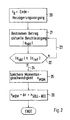
Im Folgenden soll anhand des Ablaufplanes in Figur 2 das erfindungsgemäße Verfahren
nach einer vom Fahrer gewollten Verzögerung erläutert werden. In einem ersten
Programmschritt 20 wird das Ende des Verzögerungsvorganges erkannt und damit ein
Zeitpunkt t0 definiert. Für das Erkennen des Verzögerungsvorganges wird überwacht,
ob die Bedieneinheit BE beispielsweise das Bremspedal vom Fahrer betätigt wird. Ist
der Verzögerungsvorgang beendet, wird in einem nachgeordneten Arbeitsschritt 21
der Betrag der aktuellen Beschleunigung |aakt| ermittelt. Hierfür kann die
Geschwindigkeit oder auch die Drehzahl an zwei aufeinanderfolgenden Zeitpunkten
erfaßt und daraus die Beschleunigung ermittelt werden. Vorteilhafterweise wird der
Betrag der aktuellen Beschleunigung |aakt| bestimmt und im weiteren Progammablauf
ausgewertet. Die Bestimmung und Auswertung des Betrages der Beschleunigung hat
den Vorteil, daß dieser Berechnungsschritt sowohl bei erfolgter Verzögerung als auch
bei erfolgter Beschleunigung ohne weitere Softwareanpassung durchführbar ist,
wodurch sich der Softwareumfang und damit die notwendige Speicherkapazität im
Steuergerät reduziert . In einer nachgeordneten Abfrage 22 wird der Betrag der
aktuellen Beschleunigung |aakt| mit dem Betrag einer vorgebbaren
Referenzbeschleunigung |aref| verglichen. The method according to the invention after a deceleration desired by the driver is to be explained below on the basis of the flow chart in FIG. In a
Wurde die Abfrage 22 mit "Nein" beantwortet, das heißt der Betrag der aktuellen
Beschleunigung |aakt| ist größer als der Betrag der vorgebbaren
Referenzbeschleunigung |aref|, so führt der Nein-Ausgang der Abfrage 22 über eine
Verbindung 23 zurück an den Arbeitsschritt 21, wo wiederum der Betrag der aktuellen
Beschleunigung |aakt| ermittelt wird.If
Wurde die Abfrage 22 mit "Ja" beantwortet, das heißt der Betrag der aktuellen
Beschleunigung |aakt| ist kleiner oder gleich dem Betrag der vorgebbaren
Referenzbeschleunigung, |aakt| <= |aref| so führt der Ja-Ausgang der Abfrage 22 über
eine Verbindung 24 an einen Arbeitsschritt 25. Im Arbeitsschritt 25 wird die
Momentangeschwindigkeit vMom zu dem Zeitpunkt, wenn |aakt| <= |aref| erfaßt und
abgespeichert, so daß im Steuergerät nunmehr die Momentangeschwindigkeit vMom
vorliegt. In dem darauf folgenden Arbeitsschritt 26 wird die Momentangeschwindigkeit
mit einem Geschwindigkeits-Offset beaufschlagt, wobei gilt: VMon, + Δv = vSoll-Neu.
Diese einzurechnende Geschwindigkeitsdifferenz kann betriebspunktabhängig
beispielsweise in der Applikation festgelegt und in einem entsprechenden Kennfeld
abgespeichert werden. Die neue Soll-Geschwindigkeit liegt am Ende des
erfindungsgemäßen Verfahrens etwas unterhalb der eingelesenen
Momentangeschwindigkeit. So wird erreicht, daß bei Bergauffahrt zu einem früheren
Zeitpunkt etwas weniger korrigiert wird als in der Ebene. Die neu bestimmte
Soll-Geschwindigkeit ist bis zu einer erneuten Geschwindigkeitsänderung die
maßgebliche Regelgröße.If
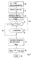
Nunmehr soll anhand des Ablaufplanes in Figur 3 das erfindungsgemäße Verfahren
nach einer Beschleunigung erläutert werden. In einem Arbeitsschritt 30 wird zunächst
das Ende des Beschleunigungsvorganges erfaßt und damit der Zeitpunkt t0 definiert.
Das Ende des Beschleunigungsvorganges wird analog zu den Ausführungen zu Figur 2
anhand der Überwachung der zugehörigen Bedieneinheit BE, beispielsweise des
Gaspedals durchgeführt. Nach dem Ende des Beschleunigungsvorganges wird in
einem anschließenden Arbeitsschritt 31 ein Timer mit einer vorgebbaren Zeit t1
gestartet. Diese Zeit t1 ist beispielsweise in Abhängigkeit des aktuellen
Betriebszustandes, welcher durch eine Erfassung verschiedener Betriebsparameter
wie Drehzahl, Last, Temperatur und Druck definiert ist, vorgebbar. Bei Beschleunigung
insbesondere bei steiler Bergabfahrt kann es vorkommen, daß die positive
Beschleunigung nicht unter den vorgegebenen Referenzwert absinkt. In diesem Fall
wird über eine vorgebbare Zeit t1 sichergestellt, daß die Momentangeschwindigkeit
auch für den Fall als neue Sollgeschwindigkeit erfaßt wird, wenn der Betrag der
Beschleunigung den entsprechenden Referenzwert nicht unterschreitet, wie dies z.B.
im Schubbetrieb auftreten kann.The method according to the invention after acceleration is now to be explained on the basis of the flow chart in FIG. 3. In a
Für das Starten einer vorgebbaren Zeit t1 gibt es verschiedene bekannte
Realisierungen, die hier nicht alle detailliert erläutert werden sollen. Eine der
einfachsten und gängigsten Varianten ist sicher, daß Laden eines Zählers mit dem
zugehörigen Wert für t1 und das anschließende Herunterzählen, so daß bei
Zählerstand Null die abgelaufene Zeit erkannt wird und die entsprechenden Aktionen
ausgelöst werden. Nach Ablauf dieser vorgebbaren Zeit t1 wird in dem nachfolgenden
Arbeitsschritt 32 der Betrag der aktuellen Beschleunigung ermittelt.There are various known implementations for starting a predefinable time t1, which are not all to be explained in detail here. One of the simplest and most common variants is to ensure that a counter is loaded with the associated value for t1 and then counted down, so that when the counter is zero, the elapsed time is recognized and the corresponding actions are triggered. After this predeterminable time t 1 has elapsed, the amount of the current acceleration is determined in the
Nach dem Ermitteln des Betrages der aktuellen Beschleunigung wird in einer
nachgeordneten Abfrage 33 ein Vergleich des Betrages der aktuellen Beschleunigung
mit dem Betrag einer vorgebbaren Referenzbeschleunigung durchgeführt. Ist der
Betrag der aktuellen Beschleunigung größer ist als der Betrag der vorgebbare
Referenzbeschleunigung, so führt der Nein-Ausgang der Abfrage 33 an eine
nachgeordnete Abfrage 34 . Hier wird geprüft, ob die Zeit t1 abgelaufen ist. Ist dies
nicht der Fall, so führt der Nein-Ausgang der Abfrage 34 über eine Verbindung 35
zurück an den Arbeitsschritt 32. Wurde die Abfrage 23 mit "Ja" beantwortet, das
heißt der Betrag der aktuellen Beschleunigung ist kleiner als der Betrag der
Referenzbeschleunigung, so führt der Ja-Ausgang der Abfrage 33 über eine
Verbindung 36 an einen Arbeitsschritt 37. Ebenfalls an den Arbeitsschritt 37 ist der
Ja-Ausgang der Abfrage 34 geführt. In der Abfrage 34 wurde geprüft , ob die Zeit t1
abgelaufen ist. Durch das Einfügen dieser zusätzlichen Zeitschleife werden nicht alle
Bewegungen der Bedieneinheit sofort umgesetzt, was wiederum einen insgesamt
ruhigeren Fahrbetrieb gewährleistet.After the amount of the current acceleration has been determined, a comparison of the amount of the current acceleration with the amount of a predefinable reference acceleration is carried out in a
Im Arbeitsschritt 37 wird die Momentangeschwindigkeit erfaßt und dieser Wert an
einen nachfolgenden Arbeitsschritt 28 geführt, in welchem die
Momentangeschwindigkeit vMom mit einer Geschwindigkeitsdifferenz Δv beaufschlagt,
wird. Dieser so ermittelte Wert ist die neue Sollgeschwindigkeit. Beim
Beschleunigungsvorgang hat das Einrechnen einer betriebspunktabhängigen
Geschwindigkeitsdifferenz den Vorteil, daß bei Bergauffahrten zu einem früheren
Zeitpunkt etwas weniger korrigiert wird als bei Bewegung des Kraftfahrzeuges in der
Ebene.
Die neu ermittelte Sollgeschwindigkeit wird nun als Regelgröße für den
übergeordneten Verfahren der Geschwindigkeitsregelung verwendet. Im
abschließenden Arbeitsschritt 39 ist das erfindungsgemäße Verfahren beendet. Ein
erneuter Start erfolgt dann, wenn der Fahrer des Fahrzeuges einen erneuten
Beschleunigungsvorgang eingeleitet hatte und dieser Vorgang durch Loslassen der
entsprechenden Bedieneinheit beendet ist.In
The newly determined target speed is now used as a control variable for the higher-level method of speed control. In the
Claims (5)
Applications Claiming Priority (2)
| Application Number | Priority Date | Filing Date | Title |
|---|---|---|---|
| DE19901527 | 1999-01-16 | ||
| DE19901527A DE19901527C1 (en) | 1999-01-16 | 1999-01-16 | Method for regulating the driving speed of a motor vehicle |
Publications (1)
| Publication Number | Publication Date |
|---|---|
| EP1020316A1 true EP1020316A1 (en) | 2000-07-19 |
Family
ID=7894454
Family Applications (1)
| Application Number | Title | Priority Date | Filing Date |
|---|---|---|---|
| EP99123465A Ceased EP1020316A1 (en) | 1999-01-16 | 1999-11-25 | Method of controlling the speed of a motor vehicle |
Country Status (5)
| Country | Link |
|---|---|
| US (1) | US6330506B1 (en) |
| EP (1) | EP1020316A1 (en) |
| JP (1) | JP2000207699A (en) |
| KR (1) | KR100628409B1 (en) |
| DE (1) | DE19901527C1 (en) |
Cited By (1)
| Publication number | Priority date | Publication date | Assignee | Title |
|---|---|---|---|---|
| WO2001079017A1 (en) * | 2000-04-17 | 2001-10-25 | Robert Bosch Gmbh | Method and device for setting the vehicle longitudinal velocity to a desired speed |
Families Citing this family (14)
| Publication number | Priority date | Publication date | Assignee | Title |
|---|---|---|---|---|
| EP1212225B1 (en) * | 1999-08-24 | 2005-06-08 | Continental Teves AG & Co. oHG | Method for adjusting a brake system of a vehicle |
| JP2003063272A (en) * | 2001-08-30 | 2003-03-05 | Hitachi Ltd | Automatic speed controller for vehicle |
| JP3977701B2 (en) * | 2002-07-17 | 2007-09-19 | 日野自動車株式会社 | Accelerator control device |
| DE10242684A1 (en) * | 2002-09-13 | 2004-03-18 | Robert Bosch Gmbh | Controlling vehicle speed and engine revolutions in vehicle with manual gear change, relates change-up probability, next gear ratio and engine speed control |
| JP2005113734A (en) * | 2003-10-06 | 2005-04-28 | Hino Motors Ltd | Accelerator control device |
| JP4938542B2 (en) * | 2007-04-27 | 2012-05-23 | トヨタ自動車株式会社 | Vehicle speed control device for vehicle |
| JP4997031B2 (en) * | 2007-09-06 | 2012-08-08 | トヨタ自動車株式会社 | Vehicle travel control device |
| JP4596016B2 (en) * | 2008-02-12 | 2010-12-08 | トヨタ自動車株式会社 | Vehicle travel control device |
| GB2471997A (en) * | 2009-07-17 | 2011-01-26 | Gm Global Tech Operations Inc | Automatic transmission control |
| DE102010006643A1 (en) * | 2010-02-03 | 2011-08-04 | GM Global Technology Operations LLC, ( n. d. Ges. d. Staates Delaware ), Mich. | Method for controlling an automatic transmission of a motor vehicle, control device for an automatic transmission of a motor vehicle and motor vehicle |
| DE102010009480B4 (en) * | 2010-02-26 | 2021-12-30 | Bayerische Motoren Werke Aktiengesellschaft | Method for storing a callable target speed for an automatic speed control |
| JP4978722B2 (en) | 2010-08-23 | 2012-07-18 | 株式会社デンソー | Speed control device |
| DE102013200391B4 (en) * | 2013-01-14 | 2022-02-17 | Robert Bosch Gmbh | Method and device for adaptive cruise control of a motor vehicle with a manual transmission |
| CN111667719B (en) * | 2019-04-25 | 2022-05-17 | 文远知行有限公司 | Apparatus and method for controlling speed of autonomous vehicle and storage medium |
Citations (2)
| Publication number | Priority date | Publication date | Assignee | Title |
|---|---|---|---|---|
| US4541052A (en) * | 1982-12-20 | 1985-09-10 | General Motors Corporation | Motor vehicle power output regulation control system |
| US5012418A (en) * | 1986-03-27 | 1991-04-30 | Zahnradfabrik Friedrichshafen, Ag. | Vehicle operating and speed regulating device |
Family Cites Families (17)
| Publication number | Priority date | Publication date | Assignee | Title |
|---|---|---|---|---|
| DE2842023A1 (en) * | 1978-09-27 | 1980-04-10 | Bosch Gmbh Robert | DIGITAL CONTROL DEVICE FOR THE SPEED OF A MOTOR VEHICLE |
| US4293844A (en) * | 1980-04-29 | 1981-10-06 | Hermann Ruhl | Variable acceleration monitoring system |
| US4598370A (en) * | 1983-01-27 | 1986-07-01 | Honda Giken Kogyo Kabushiki Kaisha | Apparatus for control of acceleration and deceleration during auto-cruise |
| JPS59136533A (en) * | 1983-01-27 | 1984-08-06 | Honda Motor Co Ltd | Apparatus for shifting operation mode of engine to automatic cruising operation |
| US4856609A (en) * | 1986-07-18 | 1989-08-15 | Mitsubishi Denki Kabushiki Kaisha | Constant-speed running control device for vehicles |
| JPS6328734A (en) * | 1986-07-18 | 1988-02-06 | Mitsubishi Electric Corp | Constant speed travel controller for vehicle |
| JPS6412930A (en) * | 1987-07-02 | 1989-01-17 | Mitsubishi Electric Corp | Constant-speed travel device for vehicle |
| JPS6412929A (en) * | 1987-07-02 | 1989-01-17 | Mitsubishi Electric Corp | Constant-speed travel device for vehicle |
| JPH0771899B2 (en) * | 1987-07-02 | 1995-08-02 | 三菱電機株式会社 | Vehicle constant-speed traveling device |
| JPH05201269A (en) * | 1992-01-29 | 1993-08-10 | Mitsubishi Electric Corp | Constant speed travel device for vehicle |
| DE4341585A1 (en) * | 1993-12-07 | 1995-06-08 | Bosch Gmbh Robert | Method and device for maintaining a predetermined driving speed of a vehicle |
| JP3341554B2 (en) * | 1995-04-27 | 2002-11-05 | 日産自動車株式会社 | Constant speed cruise control device for vehicles |
| US5680309A (en) * | 1995-06-07 | 1997-10-21 | Cummins Engine Company, Inc. | Control system for automatic resumption of speed control after gear change |
| DE19549224A1 (en) * | 1995-12-30 | 1997-07-03 | Bosch Gmbh Robert | Motor vehicle speed control method and device |
| DE19627727B4 (en) * | 1996-07-10 | 2012-05-31 | Robert Bosch Gmbh | Method and device for controlling the speed of a vehicle |
| JP3555402B2 (en) * | 1997-09-01 | 2004-08-18 | 日産自動車株式会社 | Vehicle speed control device |
| US6138071A (en) * | 1997-09-16 | 2000-10-24 | Honda Giken Kogyo Kabushiki Kaisha | Cruising control apparatus |
-
1999
- 1999-01-16 DE DE19901527A patent/DE19901527C1/en not_active Expired - Fee Related
- 1999-11-25 EP EP99123465A patent/EP1020316A1/en not_active Ceased
-
2000
- 2000-01-15 KR KR1020000001836A patent/KR100628409B1/en not_active IP Right Cessation
- 2000-01-17 JP JP7543A patent/JP2000207699A/en active Pending
- 2000-01-18 US US09/484,010 patent/US6330506B1/en not_active Expired - Fee Related
Patent Citations (2)
| Publication number | Priority date | Publication date | Assignee | Title |
|---|---|---|---|---|
| US4541052A (en) * | 1982-12-20 | 1985-09-10 | General Motors Corporation | Motor vehicle power output regulation control system |
| US5012418A (en) * | 1986-03-27 | 1991-04-30 | Zahnradfabrik Friedrichshafen, Ag. | Vehicle operating and speed regulating device |
Cited By (2)
| Publication number | Priority date | Publication date | Assignee | Title |
|---|---|---|---|---|
| WO2001079017A1 (en) * | 2000-04-17 | 2001-10-25 | Robert Bosch Gmbh | Method and device for setting the vehicle longitudinal velocity to a desired speed |
| US6591181B2 (en) | 2000-04-17 | 2003-07-08 | Robert Bosch Gmbh | Method and device for setting the vehicle longitudinal velocity to a deired speed |
Also Published As
| Publication number | Publication date |
|---|---|
| DE19901527C1 (en) | 2000-07-06 |
| US6330506B1 (en) | 2001-12-11 |
| KR20000053500A (en) | 2000-08-25 |
| JP2000207699A (en) | 2000-07-28 |
| KR100628409B1 (en) | 2006-09-28 |
Similar Documents
| Publication | Publication Date | Title |
|---|---|---|
| DE19901527C1 (en) | Method for regulating the driving speed of a motor vehicle | |
| EP0464041B1 (en) | Process for determining at least one end position of an adjusting device in a motor vehicle | |
| EP0760056B1 (en) | Process and device for controlling an internal combustion engine | |
| DE3929746A1 (en) | METHOD AND DEVICE FOR CONTROLLING AND REGULATING A SELF-IGNITIONING INTERNAL COMBUSTION ENGINE | |
| EP0278232A1 (en) | Method for controlling the travelling speed of a motor vehicle, and device for carrying out this method | |
| DE3714137C2 (en) | ||
| EP0286644B1 (en) | Process for electronic determination of the quantity of fuel of an internal combustion engine | |
| EP0347446B1 (en) | Process and device for regulating the air feed in an internal combustion engine, in particular during idling and coasting | |
| EP1028242B1 (en) | Method and apparatus for damping vibration type vehicle movements | |
| EP0930424B1 (en) | Method and apparatus for improving startoff in a vehicle equipped with a manual gearbox | |
| EP1232337B1 (en) | Method and device for the operation of a drive unit on a vehicle | |
| WO2001044644A2 (en) | Method and device for controlling the drive unit of a vehicle | |
| EP1277940B1 (en) | Method and device for the operation of a drive engine | |
| DE4223253C2 (en) | Control device for a vehicle | |
| DE4115647B4 (en) | Control system in a vehicle | |
| EP1242732B1 (en) | Method and device for controlling the drive unit of a vehicle | |
| DE3248745A1 (en) | Control system for an internal combustion engine | |
| DE3940751A1 (en) | SYSTEM FOR ELECTRONICALLY CONTROLLING AND / OR REGULATING THE PERFORMANCE OF AN INTERNAL COMBUSTION ENGINE OF A MOTOR VEHICLE | |
| EP1432899A1 (en) | Method and device for operating the drive motor of a vehicle | |
| EP1057677A1 (en) | Method for setting the desired target speed in a vehicle cruise control system | |
| DE19506082A1 (en) | Vehicle IC engine drive unit control | |
| EP1436160A1 (en) | Method and device for controlling the speed of a vehicle | |
| EP2729688A1 (en) | Method for operating an internal combustion engine | |
| DE3621555A1 (en) | DEVICE FOR ADJUSTING THE SPEED OF A MOTOR VEHICLE | |
| DE4313173B4 (en) | Method and device for controlling a variable size, especially in vehicles |
Legal Events
| Date | Code | Title | Description |
|---|---|---|---|
| PUAI | Public reference made under article 153(3) epc to a published international application that has entered the european phase |
Free format text: ORIGINAL CODE: 0009012 |
|
| AK | Designated contracting states |
Kind code of ref document: A1 Designated state(s): DE ES FR GB IT SE |
|
| AX | Request for extension of the european patent |
Free format text: AL;LT;LV;MK;RO;SI |
|
| 17P | Request for examination filed |
Effective date: 20000808 |
|
| AKX | Designation fees paid |
Free format text: DE ES FR GB IT SE |
|
| 17Q | First examination report despatched |
Effective date: 20011017 |
|
| STAA | Information on the status of an ep patent application or granted ep patent |
Free format text: STATUS: THE APPLICATION HAS BEEN REFUSED |
|
| 18R | Application refused |
Effective date: 20020415 |