EP1020232A2 - Capuchon de buse pour un pulvérisateur à gâchette - Google Patents
Capuchon de buse pour un pulvérisateur à gâchette Download PDFInfo
- Publication number
- EP1020232A2 EP1020232A2 EP00300079A EP00300079A EP1020232A2 EP 1020232 A2 EP1020232 A2 EP 1020232A2 EP 00300079 A EP00300079 A EP 00300079A EP 00300079 A EP00300079 A EP 00300079A EP 1020232 A2 EP1020232 A2 EP 1020232A2
- Authority
- EP
- European Patent Office
- Prior art keywords
- cap
- nozzle
- positions
- walls
- rotation
- Prior art date
- Legal status (The legal status is an assumption and is not a legal conclusion. Google has not performed a legal analysis and makes no representation as to the accuracy of the status listed.)
- Granted
Links
Images
Classifications
-
- B—PERFORMING OPERATIONS; TRANSPORTING
- B05—SPRAYING OR ATOMISING IN GENERAL; APPLYING FLUENT MATERIALS TO SURFACES, IN GENERAL
- B05B—SPRAYING APPARATUS; ATOMISING APPARATUS; NOZZLES
- B05B11/00—Single-unit hand-held apparatus in which flow of contents is produced by the muscular force of the operator at the moment of use
- B05B11/0005—Components or details
- B05B11/0027—Means for neutralising the actuation of the sprayer ; Means for preventing access to the sprayer actuation means
- B05B11/0032—Manually actuated means located downstream the discharge nozzle for closing or covering it, e.g. shutters
-
- B—PERFORMING OPERATIONS; TRANSPORTING
- B05—SPRAYING OR ATOMISING IN GENERAL; APPLYING FLUENT MATERIALS TO SURFACES, IN GENERAL
- B05B—SPRAYING APPARATUS; ATOMISING APPARATUS; NOZZLES
- B05B1/00—Nozzles, spray heads or other outlets, with or without auxiliary devices such as valves, heating means
- B05B1/12—Nozzles, spray heads or other outlets, with or without auxiliary devices such as valves, heating means capable of producing different kinds of discharge, e.g. either jet or spray
-
- B—PERFORMING OPERATIONS; TRANSPORTING
- B05—SPRAYING OR ATOMISING IN GENERAL; APPLYING FLUENT MATERIALS TO SURFACES, IN GENERAL
- B05B—SPRAYING APPARATUS; ATOMISING APPARATUS; NOZZLES
- B05B1/00—Nozzles, spray heads or other outlets, with or without auxiliary devices such as valves, heating means
- B05B1/30—Nozzles, spray heads or other outlets, with or without auxiliary devices such as valves, heating means designed to control volume of flow, e.g. with adjustable passages
- B05B1/32—Nozzles, spray heads or other outlets, with or without auxiliary devices such as valves, heating means designed to control volume of flow, e.g. with adjustable passages in which a valve member forms part of the outlet opening
-
- B—PERFORMING OPERATIONS; TRANSPORTING
- B05—SPRAYING OR ATOMISING IN GENERAL; APPLYING FLUENT MATERIALS TO SURFACES, IN GENERAL
- B05B—SPRAYING APPARATUS; ATOMISING APPARATUS; NOZZLES
- B05B1/00—Nozzles, spray heads or other outlets, with or without auxiliary devices such as valves, heating means
- B05B1/34—Nozzles, spray heads or other outlets, with or without auxiliary devices such as valves, heating means designed to influence the nature of flow of the liquid or other fluent material, e.g. to produce swirl
- B05B1/3405—Nozzles, spray heads or other outlets, with or without auxiliary devices such as valves, heating means designed to influence the nature of flow of the liquid or other fluent material, e.g. to produce swirl to produce swirl
- B05B1/341—Nozzles, spray heads or other outlets, with or without auxiliary devices such as valves, heating means designed to influence the nature of flow of the liquid or other fluent material, e.g. to produce swirl to produce swirl before discharging the liquid or other fluent material, e.g. in a swirl chamber upstream the spray outlet
- B05B1/3421—Nozzles, spray heads or other outlets, with or without auxiliary devices such as valves, heating means designed to influence the nature of flow of the liquid or other fluent material, e.g. to produce swirl to produce swirl before discharging the liquid or other fluent material, e.g. in a swirl chamber upstream the spray outlet with channels emerging substantially tangentially in the swirl chamber
- B05B1/3431—Nozzles, spray heads or other outlets, with or without auxiliary devices such as valves, heating means designed to influence the nature of flow of the liquid or other fluent material, e.g. to produce swirl to produce swirl before discharging the liquid or other fluent material, e.g. in a swirl chamber upstream the spray outlet with channels emerging substantially tangentially in the swirl chamber the channels being formed at the interface of cooperating elements, e.g. by means of grooves
- B05B1/3436—Nozzles, spray heads or other outlets, with or without auxiliary devices such as valves, heating means designed to influence the nature of flow of the liquid or other fluent material, e.g. to produce swirl to produce swirl before discharging the liquid or other fluent material, e.g. in a swirl chamber upstream the spray outlet with channels emerging substantially tangentially in the swirl chamber the channels being formed at the interface of cooperating elements, e.g. by means of grooves the interface being a plane perpendicular to the outlet axis
-
- B—PERFORMING OPERATIONS; TRANSPORTING
- B05—SPRAYING OR ATOMISING IN GENERAL; APPLYING FLUENT MATERIALS TO SURFACES, IN GENERAL
- B05B—SPRAYING APPARATUS; ATOMISING APPARATUS; NOZZLES
- B05B11/00—Single-unit hand-held apparatus in which flow of contents is produced by the muscular force of the operator at the moment of use
- B05B11/01—Single-unit hand-held apparatus in which flow of contents is produced by the muscular force of the operator at the moment of use characterised by the means producing the flow
- B05B11/10—Pump arrangements for transferring the contents from the container to a pump chamber by a sucking effect and forcing the contents out through the dispensing nozzle
- B05B11/1042—Components or details
- B05B11/1052—Actuation means
- B05B11/1056—Actuation means comprising rotatable or articulated levers
- B05B11/1057—Triggers, i.e. actuation means consisting of a single lever having one end rotating or pivoting around an axis or a hinge fixedly attached to the container, and another end directly actuated by the user
Definitions
- This invention relates generally to a trigger operated pump sprayer having a nozzle cap which can be more positively and safely operated without slippage, and which is capable of being more accurately set between rotative on and off positions to avoid leakage.
- the present invention comprises an improvement over U.S. patent 4,706,888, commonly owned herewith, and directed to a nozzle assembly having a four-sided nozzle cap of rectangular cross-section, opposing pairs of flat walls respectively associated with off and on rotative positions of the cap. Rotation in either direction about the central axis of the cap controls the nozzle between off and on positions.
- cap rotation As the cap is a relatively small part the operator oftentimes has difficulty in manipulating cap rotation, especially when that operator is a person whose physical adroitness may be weak, or whose hands may be wet or damp or who may simply have a weak grip.
- the user's fingers thus tend to slip off the nozzle cap upon rotation in either direction. If the cap is not fully rotated to one of its on positions, passages and grooves acting between the coaxial core and the cap skirt telescoped about that core remain mismatched such that the nozzle remains closed. As the user then further rotates the cap to assure positioning in the intended on position, the trigger may have already been actuated such that the user's hand or some other body portion of the user becomes a spray target, which is totally undesirable. Otherwise any residual liquid in the discharge passage which may have accumulated in the process of the earlier partial cap rotation, could leak on to the hand of the user when the cap is again more fully rotated to its on position.
- the nozzle cap according to the invention has radially extending ridges or flutes integrally formed along the four edges of the rectangular cap to thereby minimize the tendency for slippage of the user's fingers from the nozzle cap upon rotation between its on and off positions.
- the ridges provide stops in both directions against which the user's fingers bear upon cap rotation to thereby improve upon the grip of the cap for both operators with diminished finger dexterity and for users with wet, damp or greasy fingers. Cap rotation to its appropriate on or off positions is more accurately assured with the nozzle of the invention thereby avoiding leakage of liquid product from the discharge orifice.
- the nozzle cap and confronting portion of the pump body have cooperating means for accurately and positively setting the cap in each of its on and off positions upon cap rotation.
- a snap detent may be provided on the pump body and four detent receiving cavities may be provided on a confronting wall of the nozzle cap for accurately setting the cap in one of its on or off positions.
- Cooperation between the detent and the selected cavity provides an audible signal to the operator of the correct setting of the cap.
- small protuberances at each of the four on and off positions of the cap may be provided for cooperation with one or more depressions provided on the nozzle of the trigger sprayer pump body giving the operator a tactile signal on the correct setting of the cap.
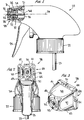
- a trigger actuated pump sprayer is generally designated 20 in Fig. 1 as comprising a pump body 21 to which a container closure 22 is coupled for mounting the sprayer to a container (not shown) of liquid to be sprayed.
- a dip tube 23 is suspended from the pump body and extends into the container, and the pump body may be covered by a separate or integral shroud 24.
- a trigger lever 25 is pivotally mounted to the pump body for actuating the pump piston (not shown) reciprocating in the pump cylinder (not shown) upon trigger actuation as known in this art.
- the pump body has a discharge barrel defining a passage 26 which terminates in a discharge nozzle 27.
- a nozzle cap 28 is mounted on the end of the nozzle by a snap fit effected between a rib on the nozzle and an internal groove on the cap, as shown.
- the cap is thereby rotatable about its central axis 29 without shifting along that axis.
- the cap has an internal sleeve 31 extending inwardly along axis 29 from an end wall 32 which contains a discharge orifice 33 on axis 29.
- the pump body has a fixed coaxial core 34, and a plug 35 is mounted on the free end of the core and is assembled to the pump body in some normal manner as to resist rotation about axis 29 upon cap rotation.
- the plug has longitudinally extending grooves terminating in radial/tangential channels which open into a spin chamber, the channels and spin chamber being located either at the terminal end of plug 35 or being formed in the confronting end wall 32 of the nozzle cap.
- the inner wall of sleeve 31 which telescopes about plug 35 has a plurality of passages which, upon rotation of the cap match with the longitudinal passages in predetermined on positions of the nozzle. A mismatch between the grooves and the passages upon cap rotation effects an off position of the nozzle.
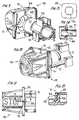
- nozzle cap 28 is of rectangular cross-section formed of four flat walls such as a first pair of opposing walls 36, 37, and a second pair of opposing walls 38, 39.
- the flat walls may be parallel to central axis 29, or may slope downwardly toward that axis in a forward direction, as shown.
- a plurality of ridges or flutes 41, 42, 43, 44 are provided along the adjoining edges of the walls forming the nozzle cap.
- the ridges each extend radially outwardly and continuously from a rearward end of the cap toward the forward end of the cap but terminate slightly from end wall 32, as shown in Fig. 3.
- Each of the ridges slope downwardly toward the central axis of the cap from the rearward to the forward ends thereof.
- a typical ridge is clearly shown in Fig. 8 as terminating a short distance from end wall 32.
- the forward ends of the flat walls are curved as typically shown at 45 for wall 38 in Fig.
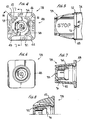
- the nozzle cap may likewise have a peripheral flange 48 (Figs. 2, 3, 4) forming a rearward wall of the nozzle cap (Fig. 6), the flange lying perpendicular to the central axis 29 of the cap.
- the flange is essentially rectangular in plan view with rounded corners and forms a back wall for each of the ridges from which the ridges extend.
- the nozzle cap is of a one-piece molded plastic construction.
- Indicia may be provided on the front face of the peripheral flange, such as OFF, SPRAY, STREAM, or ON (not shown), as shown in Fig. 4, associated with the two off modes and the two on modes of the nozzle assembly. Otherwise indicia such as STOP (Fig. 5) may be provided on the outer surfaces of walls 36, 37, and indicia such as a spray pattern symbol (Figs. 9, 10) may be provided on the outer surfaces of walls 38, 39, for respectively indicating the two on and the two off modes of the nozzle assembly.
- indicia such as STOP (Fig. 5) may be provided on the outer surfaces of walls 36, 37
- indicia such as a spray pattern symbol (Figs. 9, 10) may be provided on the outer surfaces of walls 38, 39, for respectively indicating the two on and the two off modes of the nozzle assembly.
- indicia such as a small triangle 49 (Fig. 5), with mirror image small triangles 51 on the centerline of each outer edge 52 of peripheral wall 48 may be provided for readily indicating to the operator a particular off or on position of the nozzle cap upon rotation.
- the points of the triangles or other similar indicia
- the operator is assured that the nozzle is turned completely off, or completely on as when the nozzle is rotated to one of its on positions.
- the operator grasps a first opposing pair of flat side walls 36, 37 or 38, 39 of the nozzle cap, in any normal manner as with the thumb and forefinger, from the front of the sprayer to adjust the nozzle setting.
- the opposing side walls are substantially contoured to the thumb and forefinger by reason of the specific structure of cap 28 as aforedescribed.
- the operator thus applies a rotative force in either direction whereupon the thumb and forefinger tend to shift in that rotative direction until limited by one of the pairs 41, 44 or 44, 43 or 43, 42 or 42, 41 of the ridges formed integrally as part of the nozzle cap.
- the operator's hand is thus less likely to slip when turning the nozzle cap, and less finger pressure against the opposing walls of the cap is required.
- the cap is therefore rotatable with less effort, more quickly and securely and with less regard to the condition or strength of the user's hands.
- peripheral flange 48 serves to limit the extent of any slippage of the operator's fingers along axis 29 during cap rotation.
- the flange further serves as an indicia carrier as aforedescribed.
- a spring-biased snap detent 53 located on the top side of nozzle 27 of the pump body in alignment with triangular indicia 49.
- each cavity 54 is associated with one of the flat walls of the nozzle cap which is in turn associated with one of the four on and off positions.
- the nozzle cap is shown accurately set in one of its off or stop positions as spring biased detent 53 engages with cavity 54 associated with that stop or off position.
- Indices 51, 49 are aligned in such position to inform to the operator that the nozzle is in a completely off position thereby avoiding any leakage of product from orifice 33.
- the nozzle cap is shifted to one of its on positions upon rotation of the cap about axis 29 through 90° in either direction.
- cavity 54 is moved in along a circumferential path away from detent 53 such that the dent simply slides against the smooth surface of the back of flange 48 until one of the two on positions is reached.
- detent 53 extends into its confronting cavity 54.
- a "snap” is audible to the operator by reason of the sharp outer edges of the cavity. The "snap" or the "click” heard by the operator confirms that the nozzle cap is set in its intended on position and will not stray from that position until positively rotated by the operator.
- a tactile setting arrangement can be provided such that the operator simply senses by feel that the nozzle cap is in one of its four set positions upon rotation.
- the cap is provided with small inwardly extending bosses or protuberances 55 respectively associated with triangles 51 on flange 48.
- An opposing pair of the protuberances as shown (or at least one) extend into small mating notches or depressions 56 formed in the outer surface of nozzle 27.
- the trigger sprayer has a nozzle cap which can be more easily operated without slippage and which is accurately and quickly set in one of its four on/off positions by an audio or tactile impression. When positively set in one of the two off positions, there is less tendency for leakage of product from the orifice.
Landscapes
- Containers And Packaging Bodies Having A Special Means To Remove Contents (AREA)
- Closures For Containers (AREA)
Applications Claiming Priority (2)
| Application Number | Priority Date | Filing Date | Title |
|---|---|---|---|
| US228647 | 1988-08-05 | ||
| US09/228,647 US6126090A (en) | 1999-01-12 | 1999-01-12 | Nozzle cap for trigger sprayer |
Publications (3)
| Publication Number | Publication Date |
|---|---|
| EP1020232A2 true EP1020232A2 (fr) | 2000-07-19 |
| EP1020232A3 EP1020232A3 (fr) | 2003-01-22 |
| EP1020232B1 EP1020232B1 (fr) | 2010-03-10 |
Family
ID=22858057
Family Applications (1)
| Application Number | Title | Priority Date | Filing Date |
|---|---|---|---|
| EP00300079A Expired - Lifetime EP1020232B1 (fr) | 1999-01-12 | 2000-01-07 | Capuchon de buse pour un pulvérisateur à gâchette |
Country Status (12)
| Country | Link |
|---|---|
| US (1) | US6126090A (fr) |
| EP (1) | EP1020232B1 (fr) |
| JP (1) | JP3812627B2 (fr) |
| KR (1) | KR20000052618A (fr) |
| CN (1) | CN1111098C (fr) |
| AR (1) | AR021633A1 (fr) |
| AT (1) | ATE460233T1 (fr) |
| AU (1) | AU753180B2 (fr) |
| BR (1) | BR9905950A (fr) |
| DE (1) | DE60043960D1 (fr) |
| ES (1) | ES2343102T3 (fr) |
| TW (1) | TW422742B (fr) |
Cited By (3)
| Publication number | Priority date | Publication date | Assignee | Title |
|---|---|---|---|---|
| WO2001094619A1 (fr) | 2000-06-07 | 2001-12-13 | International Reagents Corporation | Methode d'analyse de composants dans des echantillons biologiques |
| WO2004054720A1 (fr) * | 2002-12-17 | 2004-07-01 | Eric Schliemann | Dispositif de dosage |
| EP1457265A1 (fr) * | 2003-03-10 | 2004-09-15 | Saint-Gobain Calmar Inc. | Capuchon de buse pour un pistolet pulvérisateur fabriqué avec méthode de bi-injection |
Families Citing this family (25)
| Publication number | Priority date | Publication date | Assignee | Title |
|---|---|---|---|---|
| EP1407825A1 (fr) | 2002-10-10 | 2004-04-14 | Monsanto Europe S.A. | Pulvérisateur |
| RU2328424C2 (ru) | 2002-10-10 | 2008-07-10 | Монсанто Эроп С.А. | Усовершенствованная бутылка-распылитель |
| US6997397B1 (en) * | 2003-04-08 | 2006-02-14 | Continental Afa Dispensing Company | Trigger sprayer nozzle |
| US7500621B2 (en) | 2003-04-10 | 2009-03-10 | Homax Products, Inc. | Systems and methods for securing aerosol systems |
| US7007867B1 (en) | 2005-03-31 | 2006-03-07 | Raoul East Drapeau | Trigger sprayer nozzle providing flow in various directions |
| US8469292B1 (en) | 2007-04-04 | 2013-06-25 | Homax Products, Inc. | Spray texture material compositions and dispensing systems and methods |
| US8844841B2 (en) * | 2009-03-19 | 2014-09-30 | S.C. Johnson & Son, Inc. | Nozzle assembly for liquid dispenser |
| USD681470S1 (en) | 2010-01-08 | 2013-05-07 | Oms Investments, Inc. | Dispensing container |
| USD650046S1 (en) | 2011-03-01 | 2011-12-06 | Smg Brands, Inc. | Sprayer |
| US20120223161A1 (en) | 2011-03-01 | 2012-09-06 | Smg Brands, Inc. | Ready-to-use hose end sprayer |
| USD670982S1 (en) | 2011-03-01 | 2012-11-20 | Smg Brands, Inc. | Applicator |
| US20120223160A1 (en) | 2011-03-01 | 2012-09-06 | Smg Brands, Inc. | Applicator with collapsible wand |
| US9546346B2 (en) | 2011-04-07 | 2017-01-17 | The Dial Corporation | Use of polyethylene glycol to control the spray pattern of sprayable liquid abrasive cleansers |
| GB201110250D0 (en) * | 2011-06-16 | 2011-08-03 | Obrist Closures Switzerland | A trigger pump dispenser |
| US9248457B2 (en) | 2011-07-29 | 2016-02-02 | Homax Products, Inc. | Systems and methods for dispensing texture material using dual flow adjustment |
| US9156042B2 (en) | 2011-07-29 | 2015-10-13 | Homax Products, Inc. | Systems and methods for dispensing texture material using dual flow adjustment |
| WO2013096809A2 (fr) * | 2011-12-23 | 2013-06-27 | Meadwestvaco Calmar, Inc. | Dispositif d'activation d'aérosol |
| USD708301S1 (en) | 2013-03-15 | 2014-07-01 | Oms Investments, Inc. | Liquid sprayer |
| USD787326S1 (en) | 2014-12-09 | 2017-05-23 | Ppg Architectural Finishes, Inc. | Cap with actuator |
| JP6634343B2 (ja) * | 2016-05-31 | 2020-01-22 | 株式会社吉野工業所 | 液体噴出器 |
| WO2018049373A1 (fr) * | 2016-09-12 | 2018-03-15 | Rieke Corporation | Pulvérisateur à gâchette |
| JP6833987B2 (ja) * | 2016-10-18 | 2021-02-24 | フロコン, インコーポレイテッド | トリガー式ポンプディスペンサー |
| CN106824605B (zh) * | 2017-04-06 | 2022-06-28 | 市下控股有限公司 | 手持式压缩喷雾器开关的防误压自锁装置 |
| US11219910B2 (en) * | 2019-09-10 | 2022-01-11 | Silgan Dispensing Systems Corporation | Trigger sprayer with improved venting system and methods of using the same |
| USD980069S1 (en) | 2020-07-14 | 2023-03-07 | Ball Corporation | Metallic dispensing lid |
Citations (2)
| Publication number | Priority date | Publication date | Assignee | Title |
|---|---|---|---|---|
| US4706888A (en) | 1986-07-11 | 1987-11-17 | Calmar, Inc. | Multi-purpose nozzle assembly |
| US5687880A (en) | 1996-04-24 | 1997-11-18 | Afa Products, Inc. | Child lock nozzle cap assembly |
Family Cites Families (18)
| Publication number | Priority date | Publication date | Assignee | Title |
|---|---|---|---|---|
| CA938595A (en) * | 1970-06-22 | 1973-12-18 | D. Jones Gerald | Multipattern spraying apparatus |
| US3891128A (en) * | 1971-02-24 | 1975-06-24 | Smrt Thomas John | Actuator for aerosol can valve |
| US3703994A (en) * | 1971-07-06 | 1972-11-28 | Gillette Co | Adjustable spray rate actuator |
| US4020982A (en) * | 1975-10-10 | 1977-05-03 | Leeds And Micallef | Rotary shut-off nozzle |
| JPS5292906A (en) * | 1976-01-31 | 1977-08-04 | Canyon Corp | Sprayers |
| US4234128A (en) * | 1978-02-06 | 1980-11-18 | The Afa Corporation | Nozzle assembly |
| US4204614A (en) * | 1978-09-28 | 1980-05-27 | Diamond International Corporation | Fluid dispenser having a spring biased locking mechanism for a safety nozzle cap |
| US4257561A (en) * | 1979-06-05 | 1981-03-24 | Ethyl Products Company | Child-resistant dispensing nozzle assembly |
| DE3066837D1 (en) * | 1979-08-16 | 1984-04-12 | Canyon Corp | Foam dispenser |
| US4516695A (en) * | 1981-02-09 | 1985-05-14 | The Afa Corporation | Child-resistant liquid dispenser sprayer or like apparatus |
| US4779803A (en) * | 1986-08-11 | 1988-10-25 | Calmar, Inc. | Manually actuated liquid sprayer |
| US4890792A (en) * | 1988-02-19 | 1990-01-02 | Afa Products Inc. | Nozzle assembly |
| US5114052A (en) * | 1988-08-25 | 1992-05-19 | Goody Products, Inc. | Manually actuated trigger sprayer |
| US5267692A (en) * | 1989-11-16 | 1993-12-07 | Afa Products Inc. | Adjustable nozzle assembly |
| US5228600A (en) * | 1992-02-24 | 1993-07-20 | Afa Products Inc. | Child resistant nozzle for trigger sprayer |
| US5377873A (en) * | 1994-04-08 | 1995-01-03 | Sunbeam Plastics Corporation | Dispensing closure |
| US5664732A (en) * | 1995-08-16 | 1997-09-09 | Owens-Illinois Closure Inc. | Nozzle for pump dispensers |
| US5662246A (en) * | 1995-10-03 | 1997-09-02 | Owens-Illinois Closure Inc. | Tamper-deterrent nozzle for pump dispensers |
-
1999
- 1999-01-12 US US09/228,647 patent/US6126090A/en not_active Expired - Lifetime
- 1999-09-18 TW TW088116154A patent/TW422742B/zh not_active IP Right Cessation
- 1999-09-21 AU AU48847/99A patent/AU753180B2/en not_active Ceased
- 1999-10-25 JP JP30236999A patent/JP3812627B2/ja not_active Expired - Fee Related
- 1999-10-26 CN CN99122045A patent/CN1111098C/zh not_active Expired - Lifetime
- 1999-12-13 AR ARP990106319A patent/AR021633A1/es active IP Right Grant
- 1999-12-22 BR BR9905950-9A patent/BR9905950A/pt not_active IP Right Cessation
- 1999-12-29 KR KR1019990064578A patent/KR20000052618A/ko active Search and Examination
-
2000
- 2000-01-07 AT AT00300079T patent/ATE460233T1/de not_active IP Right Cessation
- 2000-01-07 DE DE60043960T patent/DE60043960D1/de not_active Expired - Lifetime
- 2000-01-07 ES ES00300079T patent/ES2343102T3/es not_active Expired - Lifetime
- 2000-01-07 EP EP00300079A patent/EP1020232B1/fr not_active Expired - Lifetime
Patent Citations (2)
| Publication number | Priority date | Publication date | Assignee | Title |
|---|---|---|---|---|
| US4706888A (en) | 1986-07-11 | 1987-11-17 | Calmar, Inc. | Multi-purpose nozzle assembly |
| US5687880A (en) | 1996-04-24 | 1997-11-18 | Afa Products, Inc. | Child lock nozzle cap assembly |
Cited By (3)
| Publication number | Priority date | Publication date | Assignee | Title |
|---|---|---|---|---|
| WO2001094619A1 (fr) | 2000-06-07 | 2001-12-13 | International Reagents Corporation | Methode d'analyse de composants dans des echantillons biologiques |
| WO2004054720A1 (fr) * | 2002-12-17 | 2004-07-01 | Eric Schliemann | Dispositif de dosage |
| EP1457265A1 (fr) * | 2003-03-10 | 2004-09-15 | Saint-Gobain Calmar Inc. | Capuchon de buse pour un pistolet pulvérisateur fabriqué avec méthode de bi-injection |
Also Published As
| Publication number | Publication date |
|---|---|
| US6126090A (en) | 2000-10-03 |
| JP3812627B2 (ja) | 2006-08-23 |
| AU753180B2 (en) | 2002-10-10 |
| ATE460233T1 (de) | 2010-03-15 |
| BR9905950A (pt) | 2000-09-26 |
| JP2000203671A (ja) | 2000-07-25 |
| EP1020232B1 (fr) | 2010-03-10 |
| AR021633A1 (es) | 2002-07-31 |
| ES2343102T3 (es) | 2010-07-23 |
| TW422742B (en) | 2001-02-21 |
| KR20000052618A (ko) | 2000-08-25 |
| AU4884799A (en) | 2000-07-13 |
| CN1111098C (zh) | 2003-06-11 |
| EP1020232A3 (fr) | 2003-01-22 |
| CN1260245A (zh) | 2000-07-19 |
| DE60043960D1 (de) | 2010-04-22 |
Similar Documents
| Publication | Publication Date | Title |
|---|---|---|
| AU753180B2 (en) | Nozzle cap for trigger sprayer | |
| US5228600A (en) | Child resistant nozzle for trigger sprayer | |
| US6478196B2 (en) | Media dispenser | |
| US5050779A (en) | Dispenser having child-resistant nozzle assembly | |
| US5297701A (en) | All plastic trigger sprayer | |
| JP3355459B2 (ja) | 流体を噴霧または分与する装置 | |
| US5169032A (en) | Tamper evident sprayer/nozzle assembly | |
| US5318206A (en) | Trigger-piston connection | |
| AU659161B2 (en) | Ergonomic trigger sprayer and hand positioner therefore | |
| EP0787103B1 (fr) | Diffuseur d'aerosol | |
| CN1805770A (zh) | 扳机喷雾器的防止儿童开启的分度喷嘴 | |
| US5161716A (en) | Dispenser having child-resistant nozzle assembly | |
| US6186366B1 (en) | Fluid dispenser with child-resistant nozzle assembly | |
| EP0954494A1 (fr) | Dispositif d'actionnement pour bombe de vaporisation avec mecanisme de fixation ameliore | |
| JP2002361126A (ja) | 手動操作流体放出装置 | |
| US6478193B1 (en) | Child-resistant nozzle assembly for fluid dispenser | |
| EP1457265B1 (fr) | Capuchon de buse pour un pistolet pulvérisateur fabriqué avec méthode de bi-injection | |
| AU3795393A (en) | Flap valve assembly for trigger sprayer | |
| US5848733A (en) | Manually operated pump dispenser having child-resistant nozzle | |
| US6364177B1 (en) | Accessories for use with aerosol containers | |
| AU674309B2 (en) | Child resistant nozzle for trigger sprayer | |
| GB2099513A (en) | A cap for an aerosol can | |
| CA1165289A (fr) | Atomiseur a gachette de pompage | |
| KR20050107766A (ko) | 무화용 또는 분주용 마이크로 펌프의 토출용 푸시버튼의커버 | |
| JP2001158483A (ja) | エアゾール容器のキャップ |
Legal Events
| Date | Code | Title | Description |
|---|---|---|---|
| PUAI | Public reference made under article 153(3) epc to a published international application that has entered the european phase |
Free format text: ORIGINAL CODE: 0009012 |
|
| AK | Designated contracting states |
Kind code of ref document: A2 Designated state(s): AT BE CH CY DE DK ES FI FR GB GR IE IT LI LU MC NL PT SE |
|
| AX | Request for extension of the european patent |
Free format text: AL;LT;LV;MK;RO;SI |
|
| PUAL | Search report despatched |
Free format text: ORIGINAL CODE: 0009013 |
|
| AK | Designated contracting states |
Kind code of ref document: A3 Designated state(s): AT BE CH CY DE DK ES FI FR GB GR IE IT LI LU MC NL PT SE |
|
| AX | Request for extension of the european patent |
Free format text: AL;LT;LV;MK;RO;SI |
|
| RIC1 | Information provided on ipc code assigned before grant |
Free format text: 7B 05B 11/00 A, 7B 05B 1/12 B |
|
| 17P | Request for examination filed |
Effective date: 20030305 |
|
| AKX | Designation fees paid |
Designated state(s): AT BE CH CY DE DK ES FI FR GB GR IE IT LI LU MC NL PT SE |
|
| 17Q | First examination report despatched |
Effective date: 20070912 |
|
| GRAP | Despatch of communication of intention to grant a patent |
Free format text: ORIGINAL CODE: EPIDOSNIGR1 |
|
| GRAS | Grant fee paid |
Free format text: ORIGINAL CODE: EPIDOSNIGR3 |
|
| GRAA | (expected) grant |
Free format text: ORIGINAL CODE: 0009210 |
|
| AK | Designated contracting states |
Kind code of ref document: B1 Designated state(s): AT BE CH CY DE DK ES FI FR GB GR IE IT LI LU MC NL PT SE |
|
| REG | Reference to a national code |
Ref country code: GB Ref legal event code: FG4D |
|
| REG | Reference to a national code |
Ref country code: CH Ref legal event code: EP |
|
| REG | Reference to a national code |
Ref country code: IE Ref legal event code: FG4D |
|
| REF | Corresponds to: |
Ref document number: 60043960 Country of ref document: DE Date of ref document: 20100422 Kind code of ref document: P |
|
| REG | Reference to a national code |
Ref country code: NL Ref legal event code: VDEP Effective date: 20100310 |
|
| REG | Reference to a national code |
Ref country code: ES Ref legal event code: FG2A Ref document number: 2343102 Country of ref document: ES Kind code of ref document: T3 |
|
| PG25 | Lapsed in a contracting state [announced via postgrant information from national office to epo] |
Ref country code: FI Free format text: LAPSE BECAUSE OF FAILURE TO SUBMIT A TRANSLATION OF THE DESCRIPTION OR TO PAY THE FEE WITHIN THE PRESCRIBED TIME-LIMIT Effective date: 20100310 Ref country code: AT Free format text: LAPSE BECAUSE OF FAILURE TO SUBMIT A TRANSLATION OF THE DESCRIPTION OR TO PAY THE FEE WITHIN THE PRESCRIBED TIME-LIMIT Effective date: 20100310 |
|
| PG25 | Lapsed in a contracting state [announced via postgrant information from national office to epo] |
Ref country code: SE Free format text: LAPSE BECAUSE OF FAILURE TO SUBMIT A TRANSLATION OF THE DESCRIPTION OR TO PAY THE FEE WITHIN THE PRESCRIBED TIME-LIMIT Effective date: 20100310 Ref country code: NL Free format text: LAPSE BECAUSE OF FAILURE TO SUBMIT A TRANSLATION OF THE DESCRIPTION OR TO PAY THE FEE WITHIN THE PRESCRIBED TIME-LIMIT Effective date: 20100310 Ref country code: GR Free format text: LAPSE BECAUSE OF FAILURE TO SUBMIT A TRANSLATION OF THE DESCRIPTION OR TO PAY THE FEE WITHIN THE PRESCRIBED TIME-LIMIT Effective date: 20100611 Ref country code: CY Free format text: LAPSE BECAUSE OF FAILURE TO SUBMIT A TRANSLATION OF THE DESCRIPTION OR TO PAY THE FEE WITHIN THE PRESCRIBED TIME-LIMIT Effective date: 20100310 |
|
| PLBE | No opposition filed within time limit |
Free format text: ORIGINAL CODE: 0009261 |
|
| STAA | Information on the status of an ep patent application or granted ep patent |
Free format text: STATUS: NO OPPOSITION FILED WITHIN TIME LIMIT |
|
| PG25 | Lapsed in a contracting state [announced via postgrant information from national office to epo] |
Ref country code: DK Free format text: LAPSE BECAUSE OF FAILURE TO SUBMIT A TRANSLATION OF THE DESCRIPTION OR TO PAY THE FEE WITHIN THE PRESCRIBED TIME-LIMIT Effective date: 20100310 Ref country code: PT Free format text: LAPSE BECAUSE OF FAILURE TO SUBMIT A TRANSLATION OF THE DESCRIPTION OR TO PAY THE FEE WITHIN THE PRESCRIBED TIME-LIMIT Effective date: 20100712 |
|
| 26N | No opposition filed |
Effective date: 20101213 |
|
| PG25 | Lapsed in a contracting state [announced via postgrant information from national office to epo] |
Ref country code: MC Free format text: LAPSE BECAUSE OF NON-PAYMENT OF DUE FEES Effective date: 20110131 |
|
| REG | Reference to a national code |
Ref country code: CH Ref legal event code: PL |
|
| PG25 | Lapsed in a contracting state [announced via postgrant information from national office to epo] |
Ref country code: CH Free format text: LAPSE BECAUSE OF NON-PAYMENT OF DUE FEES Effective date: 20110131 Ref country code: LI Free format text: LAPSE BECAUSE OF NON-PAYMENT OF DUE FEES Effective date: 20110131 |
|
| PGFP | Annual fee paid to national office [announced via postgrant information from national office to epo] |
Ref country code: NL Payment date: 20120130 Year of fee payment: 13 |
|
| PG25 | Lapsed in a contracting state [announced via postgrant information from national office to epo] |
Ref country code: LU Free format text: LAPSE BECAUSE OF NON-PAYMENT OF DUE FEES Effective date: 20110107 |
|
| REG | Reference to a national code |
Ref country code: FR Ref legal event code: PLFP Year of fee payment: 17 |
|
| REG | Reference to a national code |
Ref country code: FR Ref legal event code: PLFP Year of fee payment: 18 |
|
| REG | Reference to a national code |
Ref country code: FR Ref legal event code: PLFP Year of fee payment: 19 |
|
| PGFP | Annual fee paid to national office [announced via postgrant information from national office to epo] |
Ref country code: GB Payment date: 20190128 Year of fee payment: 20 Ref country code: ES Payment date: 20190201 Year of fee payment: 20 Ref country code: DE Payment date: 20190129 Year of fee payment: 20 Ref country code: FR Payment date: 20190125 Year of fee payment: 20 Ref country code: IT Payment date: 20190123 Year of fee payment: 20 Ref country code: IE Payment date: 20190128 Year of fee payment: 20 |
|
| PGFP | Annual fee paid to national office [announced via postgrant information from national office to epo] |
Ref country code: BE Payment date: 20190128 Year of fee payment: 20 |
|
| REG | Reference to a national code |
Ref country code: DE Ref legal event code: R071 Ref document number: 60043960 Country of ref document: DE |
|
| REG | Reference to a national code |
Ref country code: GB Ref legal event code: PE20 Expiry date: 20200106 |
|
| REG | Reference to a national code |
Ref country code: BE Ref legal event code: MK Effective date: 20200107 |
|
| REG | Reference to a national code |
Ref country code: IE Ref legal event code: MK9A |
|
| PG25 | Lapsed in a contracting state [announced via postgrant information from national office to epo] |
Ref country code: GB Free format text: LAPSE BECAUSE OF EXPIRATION OF PROTECTION Effective date: 20200106 Ref country code: IE Free format text: LAPSE BECAUSE OF EXPIRATION OF PROTECTION Effective date: 20200107 |
|
| REG | Reference to a national code |
Ref country code: ES Ref legal event code: FD2A Effective date: 20201203 |
|
| PG25 | Lapsed in a contracting state [announced via postgrant information from national office to epo] |
Ref country code: ES Free format text: LAPSE BECAUSE OF EXPIRATION OF PROTECTION Effective date: 20200108 |